Article

Design of an Ultrahigh Birefringence Photonic Crystal Fiber with Large Nonlinearity Using All Circular Air Holes for a Fiber-Optic Transmission System

by
Shovasis Kumar Biswas
1,*,
S. M. Rakibul Islam
1,
Md. Rubayet Islam
1,
Mohammad Mahmudul Alam Mia
2,
Summit Sayem
1 and
Feroz Ahmed
1
1
Department of Electrical and Electronic Engineering, Independent University Bangladesh, Dhaka 1229, Bangladesh
2
Department of Electronics & Communication Engineering, Sylhet International University, Sylhet 3100, Bangladesh
*
Author to whom correspondence should be addressed.
Photonics 2018, 5(3), 26; https://doi.org/10.3390/photonics5030026
Submission received: 11 August 2018 / Revised: 28 August 2018 / Accepted: 29 August 2018 / Published: 5 September 2018

Abstract

:
This paper proposes a hexagonal photonic crystal fiber (H-PCF) structure with all circular air holes in order to simultaneously achieve ultrahigh birefringence and high nonlinearity. The H-PCF design consists of an asymmetric core region, where one air hole is a reduced diameter and the air hole in its opposite vertex is omitted. The light-guiding properties of the proposed H-PCF structure were studied using the full-vector finite element method (FEM) with a circular perfectly matched layer (PML). The simulation results showed that the proposed H-PCF exhibits an ultrahigh birefringence of 3.87 × 10⁻², a negative dispersion coefficient of −753.2 ps/(nm km), and a nonlinear coefficient of 96.51 W−1 km−1 at an excitation wavelength of 1550 nm. The major advantage of our H-PCF design is that it provides these desirable modal properties without using any non-circular air holes in the core and cladding region, thus making the fiber fabrication process much easier. The ultrahigh birefringence, large negative dispersion, and high nonlinearity of our designed H-PCF make it a very suitable candidate for optical backpropagation applications, which is a scheme for the simultaneous dispersion and nonlinearity compensation of optical-fiber transmission links.

1. Introduction

Photonic crystal fibers (PCF) recently drew significant attention, as they exhibit extraordinary optical characteristics such as high birefringence, large effective mode area, high nonlinearity, and very low confinement loss as compared to other conventional optical fibers [1,2,3]. A typical PCF microstructure is composed of a lattice of air holes surrounded by a silica background. The waveguiding takes place at the fiber core, which may be solid or hollow. PCFs with high-index cores were shown to exhibit similar features to conventional optical fibers, where the light-guiding properties are largely based on a physical mechanism called total internal reflection (TIR). However, in order to achieve TIR in conventional fibers, a higher refractive index of the core compared to the surrounding media is required. In recent years, photonic bandgap (PBG) materials were realized for localizing and controlling light in cavities and waveguides. Periodically structured materials such as PCFs exhibit the PBG property, since certain photonic bandgaps may be forbidden by selectively choosing the lattice structure and dimensions within the crystal [4].
In high-bit-rate fiber-optic transmission systems, the major impairment for optical pulses is group velocity dispersion. Dispersion causes pulse broadening and must be compensated for when transmitting data over long distances. One of the effective methods of compensating for dispersion is simply using a highly negative dispersion fiber. Recently, photonic crystal fibers drew the attention of researchers due to some striking properties such as ultrahigh negative dispersion characteristics, high birefringence, and high nonlinearity compared to classical fibers. These modal properties make them a more suitable candidate for various application areas including telecommunications, sensors, spectroscopy, medicine, etc. [5,6]. Multicore PCFs are also finding some special applications due to their optical waveguide and photonic design possibilities, such as the development of optical splitters with larger splitting ratios and optical couplers with lower coupling lengths [7,8]. Diode-pumped alkali lasers (DPALs) are another special field of application, where embedding the alkali gas in hollow-core PCFs was shown to be an effective method of overcoming high-power limitations [9].
The PCF structure can be modified with different types of air-hole shapes and arrangements to alter the guiding properties, such as in the case of achieving ultrahigh birefringence characteristics [10,11]. For example, Wang et al. proposed a novel PCF using rectangular air holes in the core region to achieve birefringence of 1.83 × 10⁻² at 1.55 µm [11]. Zhang et al. enlarged two of the central air holes of the fiber and reported a birefringence property on a scale of 10−3 at 1550 nm [12]. Xu et al. also achieved birefringence of 10−3 by proposing a PCF consisting of a hexagonal cladding with a pentagonal core [13]. Rashid et al. designed a dodecagonal-shaped PCF and reported a birefringence of 2.05 × 10⁻², nonlinearity of 39.02 W−1 km−1, and a negative dispersion of −396.9 ps/(nm km) [14]. Golden spiral PCF designs were recently developed to obtain high birefringence values such as 1.16 × 10⁻² [15]. For instance, Agrawal et al. proposed arranging elliptical air holes in a spiral pattern to achieve a golden spiral PCF with a high birefringence of 2.2 × 10⁻² at 1.55 µm [16]. Revathi et al. also designed a spiral PCF with elliptical air holes which had a large birefringence of 2.56 × 10⁻² [17], as well as a soft glass photonic crystal fiber with a large modal birefringence of 2.96 × 10⁻² [18]. However, spiral PCFs consisting of elliptical or rectangular air holes have poor light confinement in the core region. Moreover, it is challenging to implement non-circular air holes in practice using current fabrication methods. Different types of PCF structures were suggested in order to overcome the weak confinement of light in the fiber core. For example, Shawkat et al. proposed a PCF with a defected core and hybrid cladding to get a birefringence of 4.39 × 10⁻² [19]. Chen et al. reported high birefringence of 1.5 × 10⁻² by arranging a core of elliptical air holes and a cladding of circular air holes in a hexagonal lattice [10]. Although these hybrid PCFs offer high birefringence and large nonlinearity, the challenge of fabricating elliptical air holes with perfect accuracy still remains.
For practical applications, it is not only crucial to design a PCF structure with high birefringence, large nonlinearity, and low confinement losses, but it is also easier to manufacture. Hence, if the PCF design is limited to using only circular air-hole shapes, the fiber can be easily fabricated using the drilling method or the conventional stack-and-draw technique. Several such PCFs that attain the abovementioned properties using all circular air holes were the subject of many studies. For example, Chau et al. designed a simple PCF structure using only circular air holes and obtained birefringence of about 5.501 × 10⁻³ at 1550 nm [20]. Yang et al. proposed a novel PCF with all circular air holes, with two enlarged air holes in the first ring of the cladding and three shrunken air holes in the core region. This study reported a high birefringence of 2.22 × 10⁻², a large nonlinearity of 68 W−1 km−1, and confinement losses on the order of 10−4 dB/m [21].
In this paper, we propose a highly nonlinear hexagonal-structure-based photonic crystal fiber for the application of supercontinuum generation, as well as broadband dispersion compensation. In order to analyze the various waveguiding properties of the proposed structure, the finite element method (FEM) with a perfectly matched layer (PML) was used. The hexagonal PCF (H-PCF) design consists of an asymmetric core region, where one air hole was omitted. From the simulation results, we achieved ultrahigh birefringence of 3.87 × 10⁻², a nonlinearity of 96.51 W−1 km−1, and an approximate negative dispersion of −753.2 ps/(nm km) at 1.55 µm. However, to the best of our knowledge, our reported ultrahigh birefringence is the highest achievable birefringence when using all circular air holes in the fiber core and cladding region.

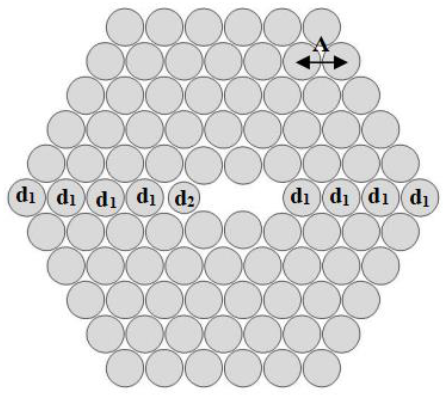
2. Design Methodology of the Proposed H-PCF

Figure 1 conveys the transverse sectional mensuration of the proposed H-PCF with proper distribution of air holes. We avoided introducing any non-circular air holes, such as rectangular- or elliptical-shaped holes, into the H-PCF structure to make the fabrication process simple. The lattice structure comprised five air-hole rings, where all of the air holes were circular in shape and the chosen background material was fused silica. The proposed H-PCF is composed of an isosceles triangular lattice with a vertex angle of 60° for producing hexagonal symmetry. The first, second, third, fourth, and fifth rings contain 5, 12, 18, 24, and 30 air holes, respectively. Hence, a total of 89 circular air holes with two different diameter values (d1 and d2) were incorporated into the design to obtain the desired ultrahigh birefringence and large nonlinearity. The diameter of one of the air holes in the core region was changed to d2, while the remainder of the air holes in the lattice had the diameter d1. Ideally, the maximum value of d1 was chosen, since a larger value will result in the overlapping of air holes within the same ring. The minimum separation between two air holes in the cladding region was about 0.015 μm in order to avoid the crosstalk effect. The distance between two consecutive air holes, i.e., the pitch, is denoted by Λ in Figure 1. The upper and lower two air holes in the core region were also relatively much larger than the air hole with diameter d2. This irregularity reduced the area of pure silica and enhanced the H-PCF’s nonlinearity and modal birefringence. Subsequently, our proposed H-PCF design had a total of three degrees of freedom (d1, d2, and Λ) which is fewer than other contemporary PCF designs such as that proposed in Reference [21], where there were five degrees of freedom. The variations in the optical characteristics of the H-PCF due to deviations in the geometric parameters (d1, d2, and Λ) were also thoroughly investigated to account for the precision of the fabrication processes.

3. Numerical Method

The finite element method (FEM) was employed as a numerical simulation tool to realize the different light-guiding properties of the proposed H-PCF structure. This includes modal properties such as birefringence, chromatic dispersion, confinement loss, and nonlinearity. In order to simulate the wavelength dependence characteristics of the H-PCF, the perfectly matched layer (PML) technique was utilized with a thickness of 10% of the cladding radius [22]. The commercially available full-vector FEM software, COMSOL Multiphysics, was employed for handling the simulation tasks for the modal analysis of the proposed H-PCF structure. Maxwell’s vector equation was solved using the FEM with circular PML for evaluating the effective refractive index (neff). The modal birefringence (B), chromatic dispersion (D(λ)), and propagation loss (αloss) could be calculated using the following equations [11,23]:
Chromatic   Dispersion , D ( λ ) = λ / c ( d 2 R e [ n e f f ] / d λ 2 ) ,
Propagation   Loss , α l o s s = 8.686 × k 0 I m [ n e f f ] × 10 3   dB / km ,
Modal   birefringence ,   B = | n x n y | ,  
where nx and ny refer to the effective refractive index of the x-polarization and y-polarization fundamental modes, respectively. Re[neff] and Im[neff] are the real and imaginary parts of neff, respectively. K0 is the free-space number, defined as K0 = 2π/λ, where λ is the wavelength and c is the velocity of light in a vacuum. The effective mode area is a crucial term for studying the nonlinear properties of microcavities [24], optical fibers, and PCFs. The effective area (Aeff) of a photonic crystal fiber in µm2, given the amplitude of the electric field in the medium (E), can be calculated as
A e f f = ( | E | 2 d x d y ) 2 | E | 4 d x d y .
Nonlinearity (γ) is inversely proportional to the effective area (Aeff), and can be written as
γ = 2 π λ × n 2 A e f f .
The nonlinearity can be enhanced using doped materials in the core region, since nonlinearity highly depends on the Kerr constant (n2) of the material.

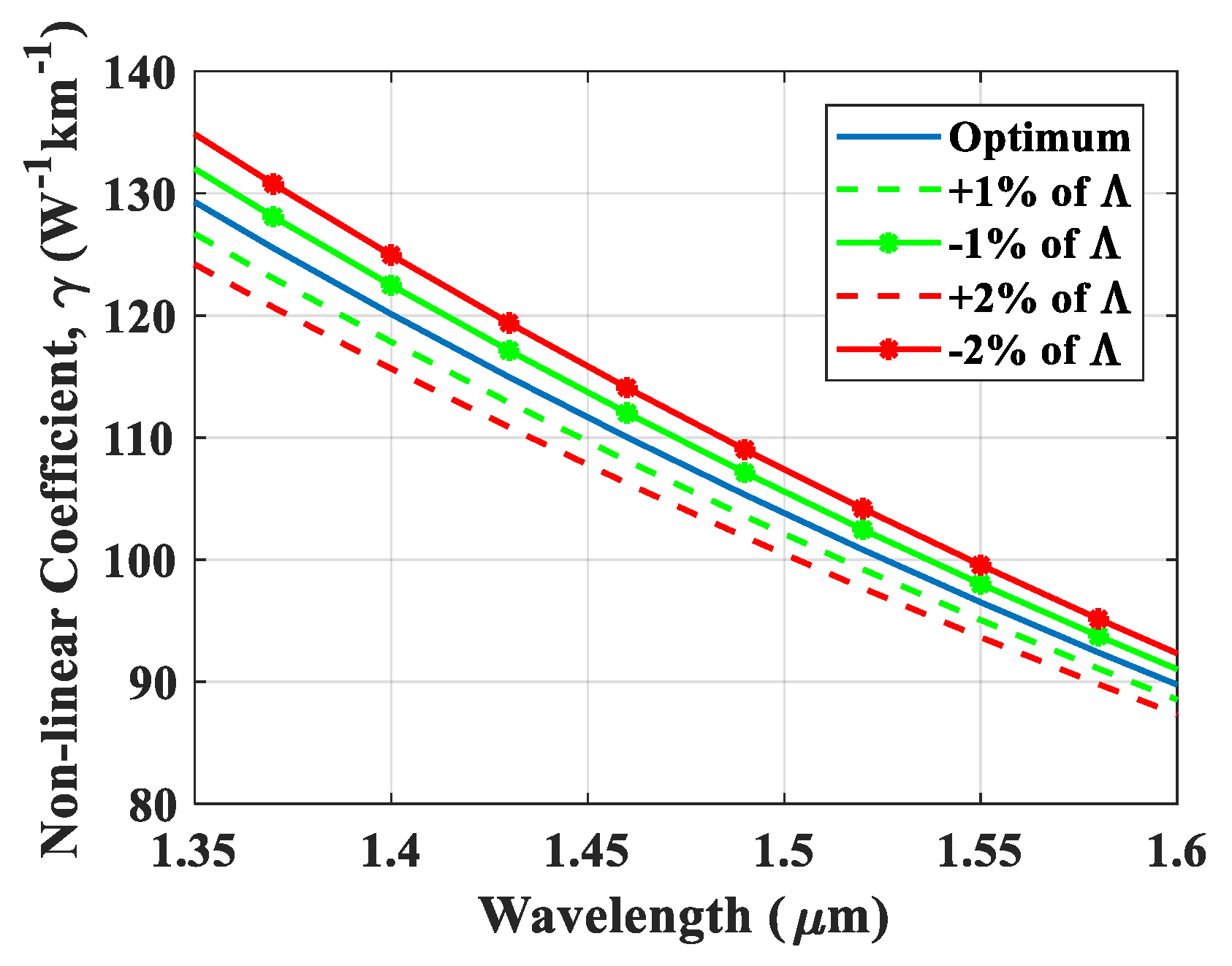
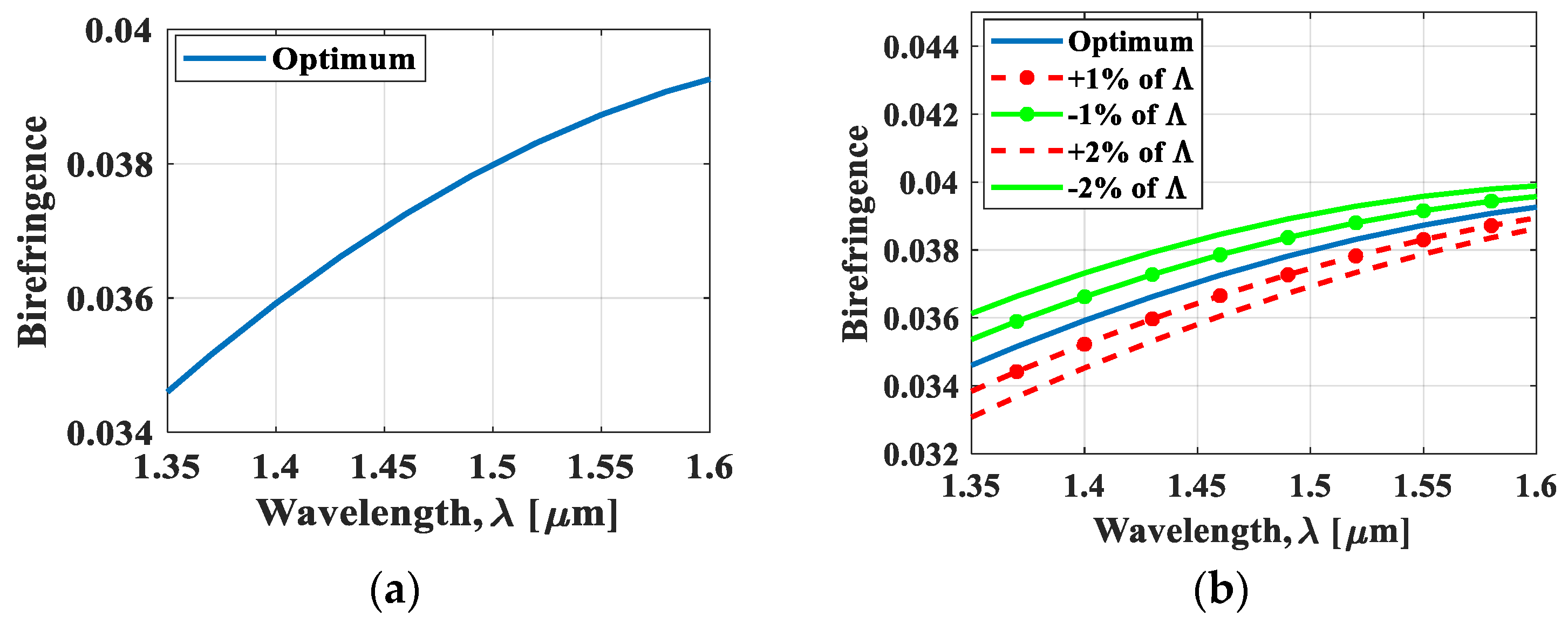
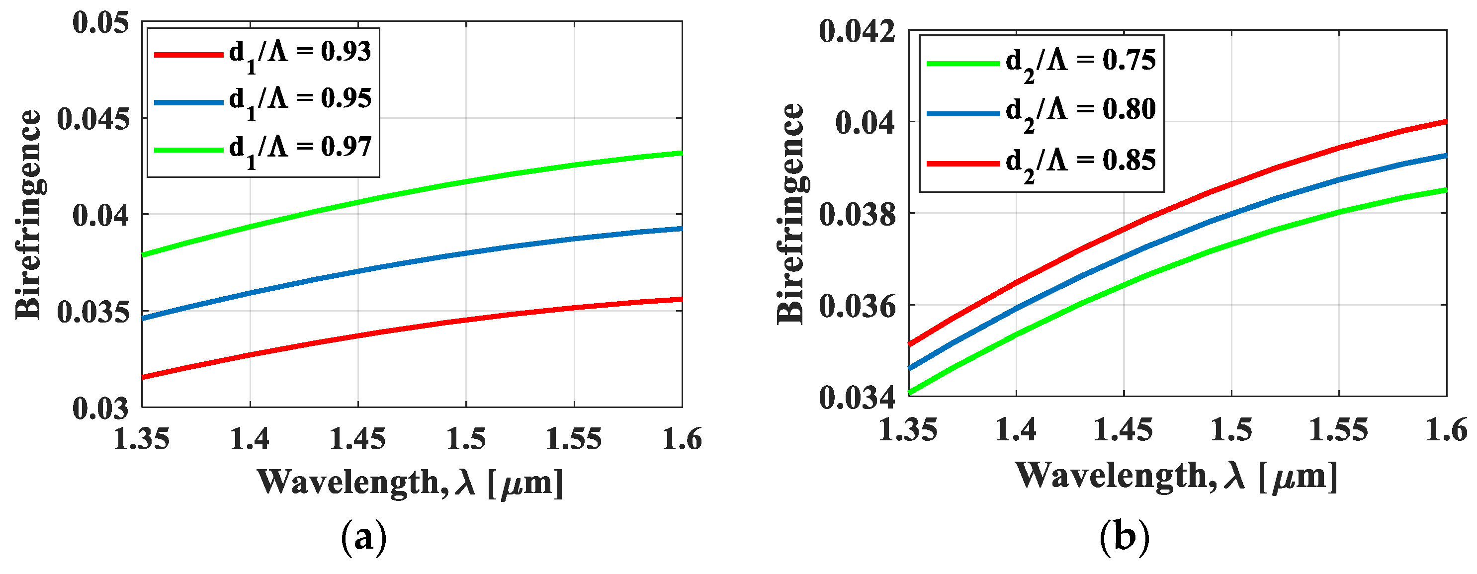
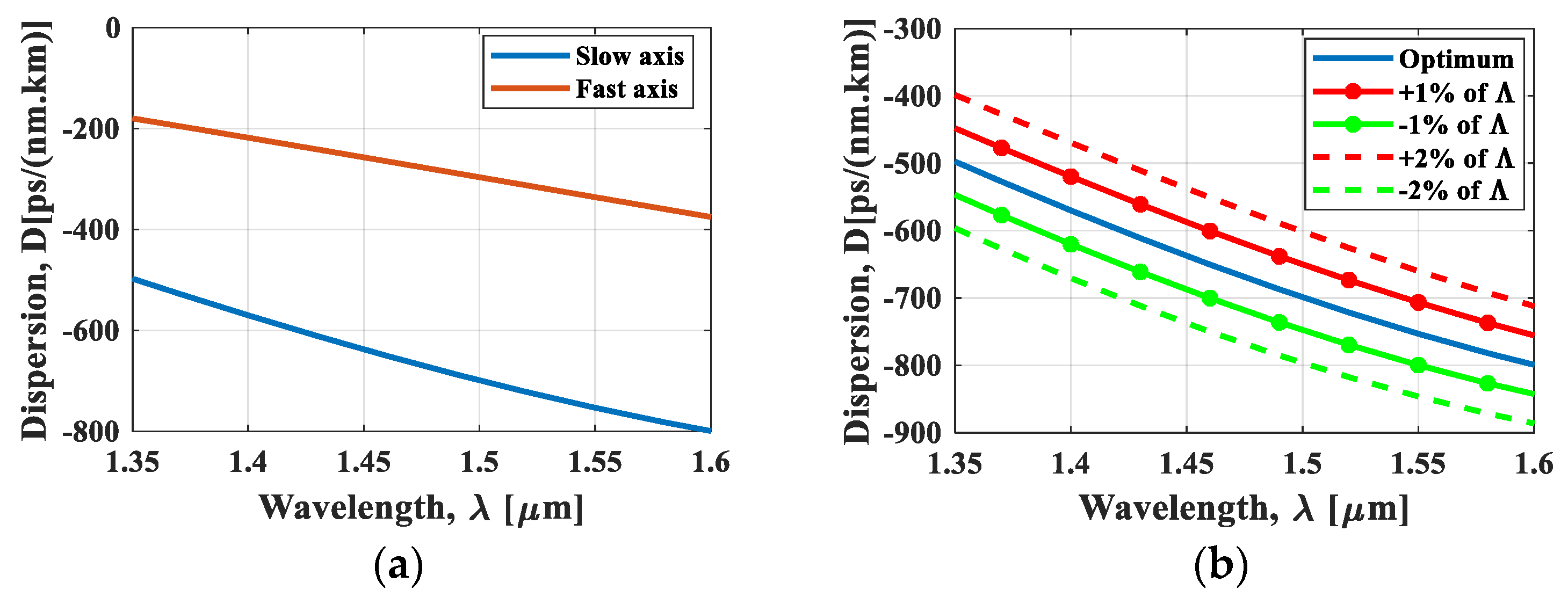
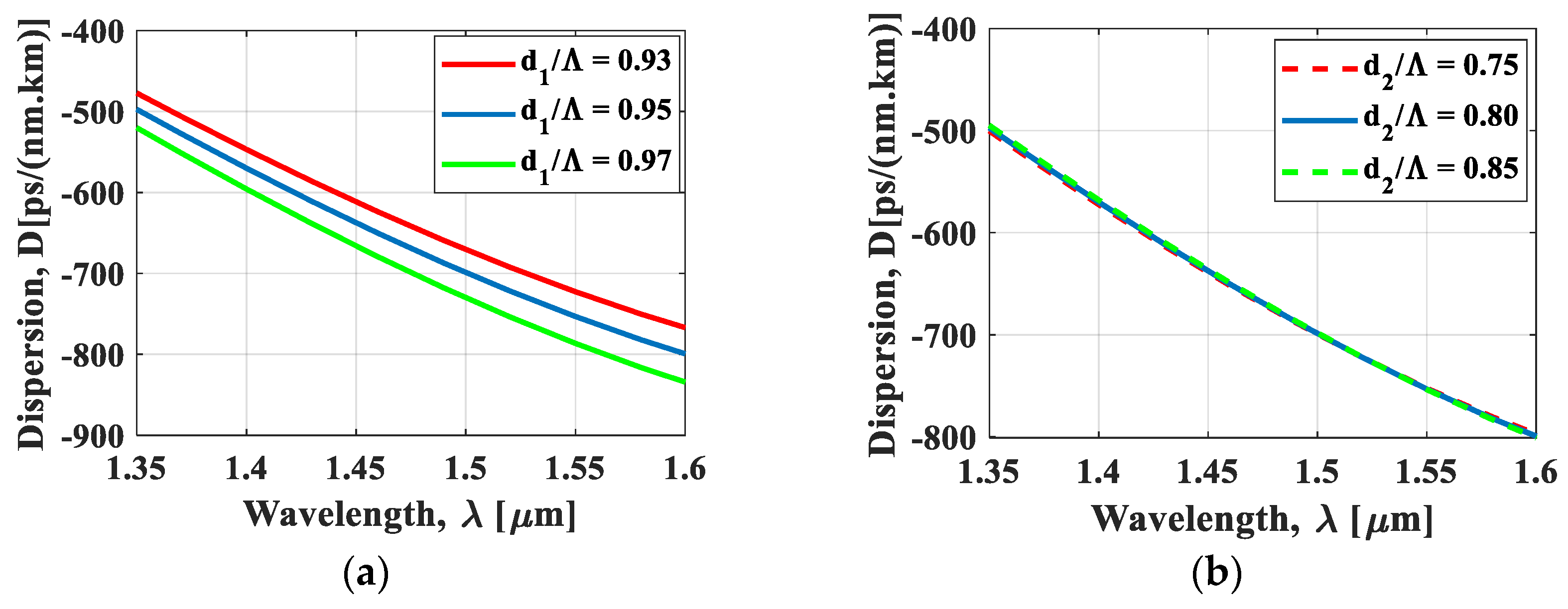
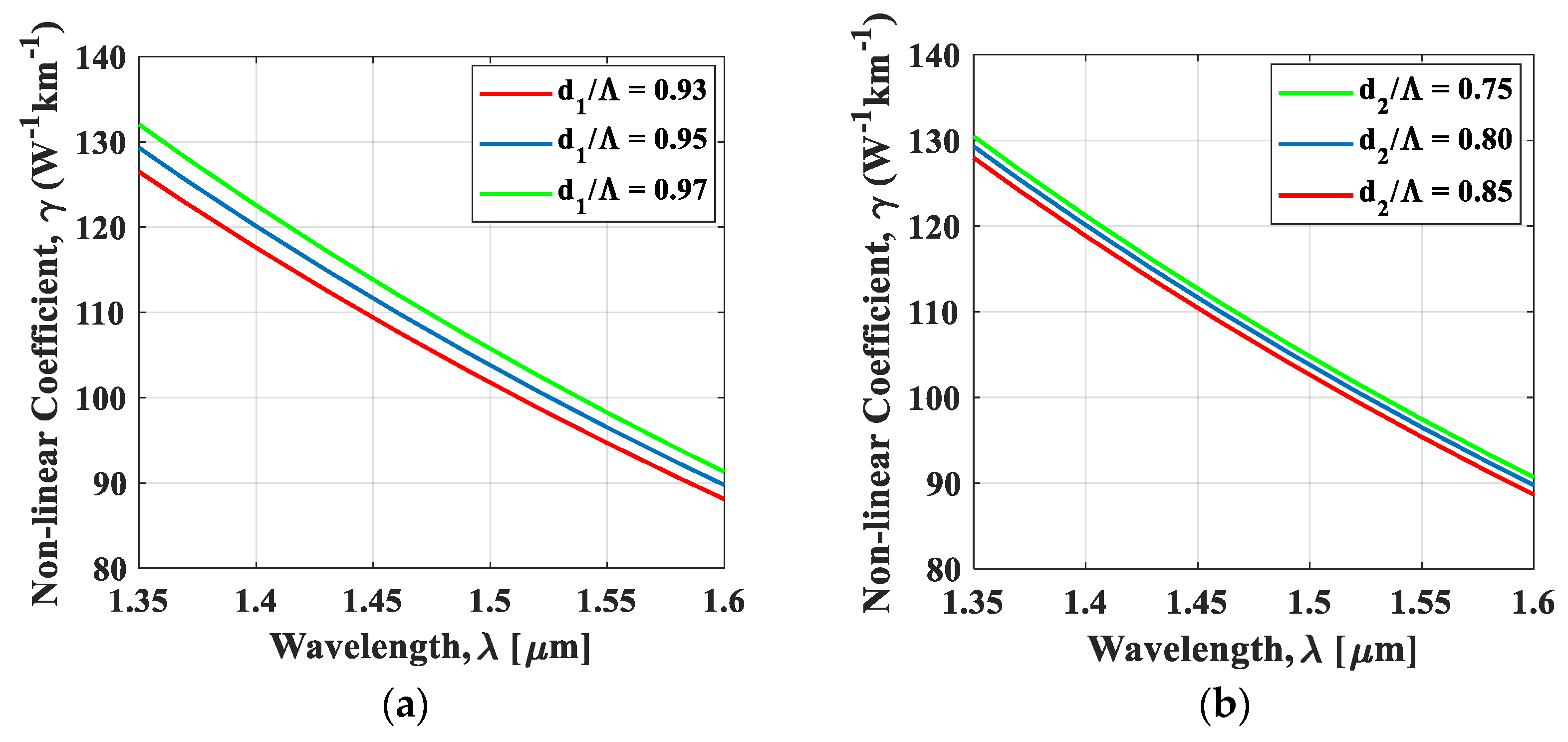
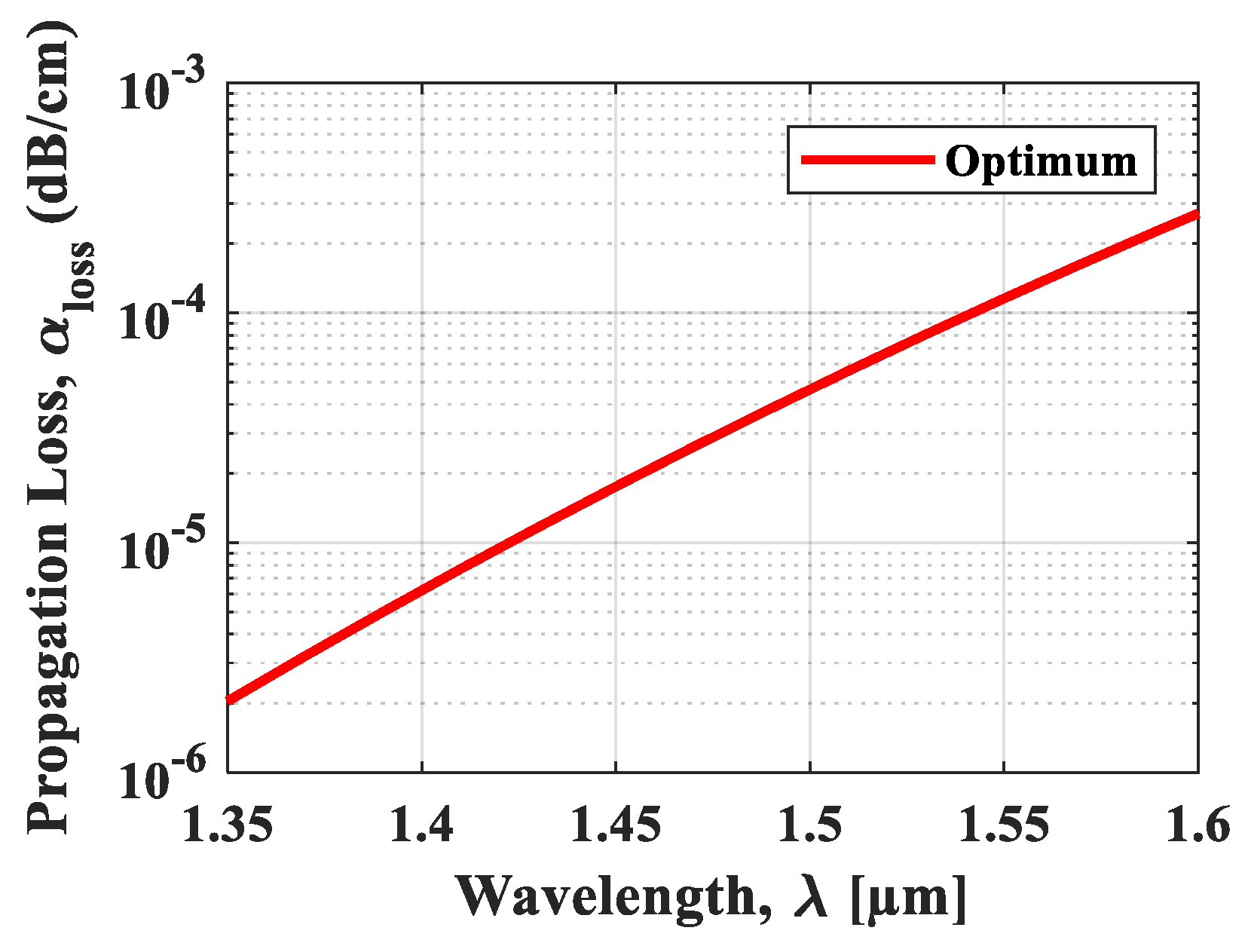
4. Simulation Results and Discussion

Figure 2a shows the modal birefringence characteristics of the proposed H-PCF as a function of wavelength (λ) when the pitch was 0.76 µm. From the figure, it can be observed that the H-PCF structure shows an ultrahigh birefringence of about 3.87 × 10⁻² at 1.55 µm. A ±1% variation in the air hole-to-hole spacing is generally considered in the simulation process to account for the practical accuracy of the PCF fabrication technique. Considering this fabrication issue, the pitch was varied from ±1 to ±2%, and its impact on the birefringence and dispersion results was studied. The effect of this pitch variation on birefringence is demonstrated in Figure 2b, where it is evident that the birefringence increases as the pitch decreases. This is due to the increasing asymmetry in the core and cladding region with decreasing pitch, which leads to a larger contrast in refractive index. Consequently, light confinement and birefringence also increase as pitch decreases.
Figure 3a shows the effect of changing d1/Λ on the birefringence characteristics, while the pitch (Λ) = 0.76 and d2/Λ = 0.80 parameters were kept fixed. According to the variation in d1/Λ to 0.93, 0.95, and 0.97, the calculated birefringence values were 3.51 × 10⁻², 3.87 × 10⁻², and 4.25 × 10⁻², respectively, at λ = 1.55 µm. It is clearly shown that changing the d1/Λ parameter results in drastic changes to the birefringence characteristics of the fiber, as the effective refractive index of both x- and y-polarized modes decreases with diameter d1. However, nx,eff decreases at a faster rate compared to ny,eff because nx,eff is more sensitive to changes in d1. As a result, birefringence increases almost linearly with d1, as the structure exhibits larger index differences between the two polarization modes. Next, d2/Λ was changed while the pitch (Λ) = 0.76 and d1/Λ = 0.95 parameters were kept fixed. The variations in d2/Λ to 0.75, 0.80, and 0.85 resulted in birefringence values of 3.80 × 10⁻², 3.87 × 10⁻², and 3.94 × 10⁻², respectively, at the wavelength of 1550 nm. From Figure 3b, it can be clearly seen that changing the d2/Λ parameter results in very slight changes to the birefringence characteristics as compared to changes in the d1/Λ parameter. Essentially, the proposed H-PCF offers an ultrahigh birefringence of about 3.87 × 10⁻², which is approximately 77 times larger than the current ordinary PM fibers with a modal birefringence of about 5 × 10⁻⁴. This means that our H-PCF can act as a good substitute for PM fibers in fiber sensors, lasers, and filters [25]. It is worth mentioning that the birefringence of the proposed H-PCF can be further increased if a background material with a higher refractive index, i.e., AsSe2 glass, is used instead of silica.
Figure 4a demonstrates the dispersion characteristics for both x- and y-polarizations, using the optimal pitch (Λ) = 0.76, d1/Λ = 0.95, and d2/Λ = 0.80. According to the figure, the proposed H-PCF demonstrates a large negative dispersion coefficient of about −753.2 ps/(nm km) along the y-polarization at an operating wavelength of 1550 nm. Figure 4b accordingly shows the effect of varying pitch from ±1 to ±2% on the chromatic dispersion, when the remaining parameters were kept constant. It can be observed from the figure that the value of dispersion becomes more and more negative with decreasing values of pitch. For the pitch variation of −1%, the dispersion was calculated as −620.3 ps/(nm km), −799.8 ps/(nm km), and −850.8 ps/(nm km) at wavelengths of 1.4 µm, 1.55 µm, and 1.61 µm, respectively, whereas the dispersion for the optimal value of pitch was −753.2 ps/(nm km) at an excitation wavelength of 1.55 µm.
Figure 5a shows the results of the dispersion characteristics when only the d1/Λ parameter was changed, while the pitch (Λ) = 0.76 and d2/Λ = 0.80 parameters were kept constant. When d1/Λ was changed to 0.93, 0.95, and 0.97, the calculated dispersion coefficients were −722.6 ps/(nm km), −753.2 ps/(nm km), and −786.5 ps/(nm km), respectively, at λ = 1.55 µm. It can also be seen in Figure 5a that changing the d1/Λ parameter led to slight variations in the dispersion coefficient. On the other hand, Figure 5b shows the effect of changing d2/Λ on the dispersion results, while the pitch (Λ) = 0.76 and d1/Λ = 0.95 parameters were kept fixed. Upon changing d2/Λ to 0.75, 0.80, and 0.85, the calculated dispersion coefficients were calculated as −752.5 ps/(nm km), −753.2 ps/(nm km), and −753.7 ps/(nm km), respectively, at λ = 1.55 µm. These results indicate that changing the d2/Λ parameter led to even smaller variations in the dispersion coefficient compared to changing the d1/Λ parameter. Nonetheless, our optimal value for the negative dispersion coefficient was about −753.2 ps/(nm km) at λ = 1.55 µm. This fairly large negative dispersion makes our fiber suitable for broadband dispersion compensation in high-speed optical transmission systems and also in polarization-maintaining applications. Moreover, the large negative dispersion of our H-PCF, combined with its ultrahigh birefringence, makes it particularly suitable for dispersion compensation and sensing applications [26].
Figure 6 demonstrates the effect of pitch deviation on nonlinearity in the 1.35–1.6-µm wavelength range. Since the effective area is inversely proportional to nonlinearity, the proposed structure achieved very large nonlinearity of 96.51 W−1 km−1 at 1550-nm wavelength, which also increased with decreasing pitch. The results of independently varying d1/Λ and d2/Λ on nonlinearity were also investigated, and the results are shown in Figure 7a,b respectively. As d1 increased, the effective refractive indices of both the x-polarized mode (nx,eff) and y-polarized mode (ny,eff) decreased while their corresponding nonlinear coefficients increased. This is due to the fact that a larger d1 corresponds to a greater filling fraction of the air holes, which, in turn, results in a lower average refractive index of the cladding. Furthermore, the increase in d1 in the cladding region nibbles the area of the core, resulting in a higher concentration of light. As a consequence, decreasing effective refractive indices and increasing nonlinear coefficients were observed for both the x- and y-polarized modes. From the figures, it can also be observed that higher values of d1/Λ and d2/Λ resulted in higher nonlinear coefficients. Nevertheless, the obtained value of nonlinearity was convincingly large enough for supercontinuum generation application, provided that the negative dispersion properties of our H-PCF are sufficiently compensated [27].
Figure 8 shows the wavelength dependence properties of propagation loss with the optimal parameter of the pitch (0.76 μm). The propagation loss was small, on the order of 10−4, for the proposed structure. This is because light was strongly confined to the core region. Moreover, a smaller value of pitch will also lead to strong light confinement. It can be observed that, at 1550-nm wavelength, the optimal value of propagation loss was 0.0001156 dB/cm. Since propagation loss strongly depends on the cladding region, one can easily improve the propagation loss by adding a number of air-hole rings in the cladding region.
Figure 9 shows the electric-field distribution of our proposed H-PCF structure using a pitch of 0.76 µm for both x- and y-polarization modes, at λ = 1.55 µm. From Figure 9, it can be confirmed that both the x- and y-polarization modes were strongly confined within the core region. This is because the core region of our proposed H-PCF structure was effectively enclosed by introducing two circular air holes in the first ring, thus leading to stronger confinement of light in the core region. Moreover, smaller values of the pitch will also lead to greater light confinement.
Finally, in Table 1, we compared the modal properties of our designed H-PCF structure with other contemporary PCF designs from related works. In the table, we presented the comparison in terms of dispersion, birefringence, effective mode area, and nonlinearity at the effective wavelength of 1.55 µm. The shape of the air holes used to design each structure was also taken into account, since the feasibility of fabricating the actual fiber is also an issue. From the table, the proposed H-PCF had a comparable dispersion value to Reference [28], which also used circular air holes. In contrast, Reference [29] used a square PCF lattice with circular and elliptical air-hole shapes to get a very large negative dispersion compared to our results. However, considering the objectives of this study, the proposed H-PCF achieved the highest birefringence value compared to all the other PCF designs. Other works reported in the table were also aimed at achieving ultrahigh birefringence values; however, the proposed H-PCF design surpasses them all using only circular air holes, which was one of the goals of its design. The proposed fiber had the lowest effective area overall, and it also had the highest nonlinearity. Only Reference [29] had nonlinearity which was comparable to our results; however, considering the manufacturing complexity of elliptical air holes, the proposed fiber has an advantage. The proposed PCF achieved the highest birefringence, lowest effective area, and highest nonlinearity in comparison to all the other PCF designs with both circular and elliptical air holes.
A key challenge when designing any PCF structure is ensuring the maximum feasibility of the fabrication process. The drilling method is generally used for fabricating PCFs with a small number of air holes, but it is restricted to circular air-hole shapes only. Non-circular air holes are difficult to implement using the widely used stack-and-draw method, since the holes can undergo re-circularization or other deformations due to the consequences of heating, surface tension, viscous stresses, and pressure changes during the preform stage [31]. Hence, more complex techniques recently emerged for fabricating elliptical- or spiral-shaped PCFs, such as the sol–gel method [32]. Apart from the standard drilling and stack-and-draw methods, a newer fabrication method called the capillary-stacking technique was proposed by Argyros et al. [33] for fabricating PCFs with circular air holes. The proposed H-PCF can be easily fabricated using these relatively simple methods, since the design uses only circular air-hole shapes in both the core and cladding region. It should also be pointed out that the proposed H-PCF gives additional design flexibility, using only two different air-hole diameters.
One of the major applications of the proposed H-PCF can be for ideal optical backpropagation purposes. An ideal optical backpropagation scheme simultaneously compensates for both dispersion and nonlinear effects introduced in optical transmission fibers. Typically, such schemes consist of optical phase conjugators, high-dispersion-compensating fibers, and also highly nonlinear fibers [34]. However, an optical backpropagation scheme involving dispersion-compensating and highly nonlinear fibers was recently studied [35]. Hence, the proposed H-PCF provides an added advantage for optical backpropagation applications, due to its coexisting large negative dispersion and high nonlinearity. Moreover, the ultrahigh birefringence and large nonlinearity of the proposed H-PCF means that comparatively shorter lengths of fiber will be required during practical applications.

5. Conclusions

In conclusion, we proposed a hexagonal PCF with all circular air holes to obtain both ultrahigh birefringence and high nonlinearity. From the simulation results, the proposed H-PCF design showed an ultrahigh modal birefringence of 3.87 × 10⁻² and a large nonlinear coefficient of 96.51 W−1 km−1 at the operating wavelength of 1550 nm. The advantage of our H-PCF design over contemporary PCF designs is that it achieves the highest birefringence and nonlinearity results using only circular air holes in the core and cladding region, thus making the fiber feasible to manufacture using current existing fabrication techniques. A negative dispersion coefficient ranging from −482.6 ps/(nm km) to −830.8 ps/(nm km) was obtained in the wavelength range of 1.34 µm to 1.64 µm. The large negative dispersion and high nonlinearity indicate that the proposed H-PCF is a potential candidate for optical backpropagation schemes, while the large negative dispersion and ultrahigh birefringence make it useful for dispersion compensation purposes.

Author Contributions

S.K.B. and M.M.A.M. designed the model and performed the numerical simulations. M.R.I. and S.M.R.I. performed the calculations and Matlab simulations. S.K.B. and S.S. wrote the manuscript with input from all authors. F.A. and S.K.B. proposed the core idea, and were in change of overall direction and planning when performing the numerical simulations. All authors discussed the results and contributed to the final manuscript.

Funding

The author acknowledges financial support from the Independent University, Bangladesh.

Acknowledgments

The authors would like to thank Shiva Kumar (McMaster University, Department of Electrical and Computer Engineering, Canada) for giving valuable suggestions and comments to improve the manuscript.

Conflicts of Interest

The authors declare that there are no conflicts of interest regarding the publication of this paper.

References

  1. Sonne, A.; Ouchar, A. Improving of high birefringence photonic crystal fiber with low confinement loss using small elliptical air holes in the core region. J. Mod. Opt. 2015, 62, 588–592. [Google Scholar] [CrossRef]
  2. Sonne, A.; Ouchar, A.; Sonne, K. Improving of high birefringence with negative dispersion using double octagonal lattice photonic crystal fiber. Int. J. Light Electron Opt. 2016, 127, 8–10. [Google Scholar] [CrossRef]
  3. Hao, R.; Li, Z.; Sun, G.; Niu, L.; Sun, Y. Analysis on photonic crystal fibers with circular air holes in elliptical configuration. Opt. Fiber Technol. 2013, 19, 363–368. [Google Scholar] [CrossRef]
  4. Broeng, J.; Mogilevstev, D.; Barkou, S.E.; Bjarklev, A. Photonic crystal fibers: A new class of optical waveguides. Opt. Fiber Technol. 1999, 5, 305–330. [Google Scholar] [CrossRef]
  5. Malka, D.; Peled, A. Power splitting of 1× 16 in multicore photonic crystal fibers. Appl. Surf. Sci. 2017, 417, 34–39. [Google Scholar] [CrossRef]
  6. Malka, D.; Cohen, E.; Zalevsky, Z. Design of 4× 1 power beam combiner based on multiCore photonic crystal fiber. Appl. Sci. 2017, 7, 695. [Google Scholar] [CrossRef]
  7. Malka, D.; Zalevsky, Z. Multicore photonic crystal fiber based 1× 8 two-dimensional intensity splitters/couplers. Electromagnetics 2013, 33, 413–420. [Google Scholar] [CrossRef]
  8. Malka, D.; Sintov, Y.; Zalevsky, Z. Fiber-laser monolithic coherent beam combiner based on multicore photonic crystal fiber. Opt. Eng. 2013, 54, 011007. [Google Scholar] [CrossRef]
  9. Sintov, Y.; Malka, D.; Zalevsky, Z. Prospects for diode-pumped alkali-atom-based hollow-core photonic-crystal fiber lasers. Opt. Lett. 2014, 39, 4655–4658. [Google Scholar] [CrossRef] [PubMed]
  10. Chen, D.; Shen, L. Ultrahigh birefringent photonic crystal fiber with ultralow confinement loss. IEEE Photonics Technol. Lett. 2007, 19, 185–187. [Google Scholar] [CrossRef]
  11. Wang, W.; Yang, B.; Song, H.; Fan, Y. Investigation of high birefringence and negative dispersion photonic crystal fiber with hybrid crystal lattice. Int. J. Light Electron Opt. 2013, 124, 2901–2903. [Google Scholar] [CrossRef]
  12. Zhang, M.Y.; Li, S.G.; Yao, Y.Y.; Zhang, L.; Fu, B.; Yin, G.B. Influence of microstructured core on characteristics of photonic crystal fibers. Acta Phys. Sin. 2010, 59, 3278–3284. [Google Scholar]
  13. Xu, D.; Song, H.; Wang, W.; Fan, Y.; Yang, B. Numerical analysis of a novel high birefringence photonic crystal fiber. Int. J. Light Electron Opt. 2013, 124, 1290–1293. [Google Scholar] [CrossRef]
  14. Rashid, M.M.; Anower, M.S.; Hasan, M.R.; Tabassum, N. Hexagonal shaped core dodecagonal PCF with high birefringence and nonlinear coefficient. In Proceedings of the International Conference on Electrical, Computer and Communication Engineering (ECCE), Cox’s Bazar, Bangladesh, 16–18 February 2017; pp. 447–450. [Google Scholar]
  15. Agrawal, A.; Kejalakshmy, N.; Chen, J.; Rahman, B.M.A.; Grattan, K.T.V. Golden spiral photonic crystal fiber: Polarization and dispersion properties. Opt. Lett. 2008, 33, 2716–2718. [Google Scholar] [CrossRef] [PubMed]
  16. Agrawal, A.; Kejalakshmy, N.; Rahman, B.M.A.; Grattan, K.T.V. Polarization and dispersion properties of elliptical hole golden spiral photonic crystal fiber. Appl. Phys. B 2010, 99, 717–726. [Google Scholar] [CrossRef] [Green Version]
  17. Revathi, S.; Inbathini, S.R.; Saifudeen, R.A. Highly nonlinear and birefringent spiral photonic crystal fiber. Adv. OptoElectron. 2014, 2014, 464391. [Google Scholar] [CrossRef]
  18. Revathi, S.; Inabathini, S.; Sandeep, R. Soft glass spiral photonic crystal fiber for large nonlinearity and high birefringence. Opt. Appl. 2015, 45, 15–24. [Google Scholar]
  19. Shawkat, M.T.B.; Razzak, S.M.A.; Kabir, S. Defected core hybrid cladding photonic crystal fiber with high birefringence & highly negative dispersion properties. In Proceedings of the 2015 IEEE International WIE Conference on Electrical and Computer Engineering (WIECON-ECE), Dhaka, Bangladesh, 19–20 December 2015; pp. 507–510. [Google Scholar]
  20. Chou Chau, Y.F.; Lim, C.M.; Yoong, V.N.; Syafi’ie Idris, M.N. A simple structure of all circular-air-holes photonic crystal fiber for achieving high birefringence and low confinement loss. J. Appl. Phys. 2015, 118, 243102. [Google Scholar] [CrossRef]
  21. Yang, T.; Wang, E.; Jiang, H.; Hu, Z.; Xie, K. High birefringence photonic crystal fiber with high nonlinearity and low confinement loss. Opt. Express 2015, 23, 8329–8337. [Google Scholar] [CrossRef] [PubMed]
  22. Islam, M.T.; Moctader, M.G.; Ahmed, K.; Chowdhury, S. Benzene Shape Photonic Crystal Fiber Based Plasma Sensor: Design and Analysis. Photonic Sens. 2018, 8, 263–269. [Google Scholar] [CrossRef]
  23. Wang, F.; Sun, Z.; Liu, C.; Sun, T.; Chu, P.K. A highly sensitive dual-core photonic crystal fiber based on a surface plasmon resonance biosensor with silver-graphene layer. Plasmonics 2017, 12, 1847–1853. [Google Scholar] [CrossRef]
  24. Kumar, S.; Biswas, S.K. Impact of Kerr nonlinearity and stimulated Raman scattering on the whispering gallery modes of an optical microsphere. JOSA B 2016, 33, 1677–1687. [Google Scholar] [CrossRef]
  25. Hasan, M.R.; Anower, M.S.; Hasan, M.I. Polarization maintaining highly nonlinear photonic crystal fiber with closely lying two zero dispersion wavelengths. Opt. Eng. 2016, 55, 056107. [Google Scholar] [CrossRef]
  26. Hasan, M.R.; Islam, M.A.; Rifat, A.A.; Hasan, M.I. A single-mode highly birefringent dispersion-compensating photonic crystal fiber using hybrid cladding. J. Mod. Opt. 2017, 64, 218–225. [Google Scholar] [CrossRef]
  27. Lee, J.H.; Teh, P.C.; Yusoff, Z.; Ibsen, M.; Belardi, W.; Monro, T.M.; Richardson, D.J. A holey fiber-based nonlinear thresholding device for optical CDMA receiver performance enhancement. IEEE Photonics Technol. Lett. 2002, 14, 876–878. [Google Scholar] [CrossRef] [Green Version]
  28. Haque, M.M.; Rahman, M.S.; Habib, M.S.; Habib, M.S. A single mode hybrid cladding circular photonic crystal fiber dispersion compensation and sensing applications. Photonics Nanostruct. Fundam. Appl. 2015, 14, 63–70. [Google Scholar] [CrossRef]
  29. Islam, M.I.; Khatun, M.; Ahmed, K. Ultra-high negative dispersion compensating square lattice based single mode photonic crystal fiber with high nonlinearity. Opt. Rev. 2017, 24, 147–155. [Google Scholar] [CrossRef]
  30. Hasan, M.I.; Habib, M.S.; Razzak, S.M.A. An elliptical-shaped core residual dispersion compensating octagonal photonic crystal fiber. IEEE Photonics Technol. Lett. 2014, 26, 2047–2050. [Google Scholar] [CrossRef]
  31. Issa, N.A.; van Eijkelenborg, M.A.; Fellew, M.; Cox, F.; Henry, G.; Large, M.C. Fabrication and study of microstructured optical fibers with elliptical holes. Opt. Lett. 2004, 29, 1336–1338. [Google Scholar] [CrossRef] [PubMed]
  32. Bise, R.T.; Trevor, D. Solgel-derived microstructured fibers: Fabrication and characterization. In Proceedings of the Optical Fiber Communication Conference (OWL6), Anaheim, CA, USA, 6 March 2005. [Google Scholar]
  33. Argyros, A.; Bassett, I.M.; Van Eijkelenborg, M.A.; Large, M.C.; Zagari, J.; Nicorovici, N.A.; McPhedran, R.C.; de Sterke, C.M. Ring structures in microstructured polymer optical fibres. Opt. Express 2001, 9, 813–820. [Google Scholar] [CrossRef] [PubMed]
  34. Shao, J.; Kumar, S. Optical backpropagation for fiber-optic communications using optical phase conjugation at the receiver. Opt. Lett. 2012, 37, 3012–3014. [Google Scholar] [CrossRef] [PubMed]
  35. Kumar, S.; Yang, D. Optical backpropagation for fiber-optic communications using highly nonlinear fibers. Opt. Lett. 2011, 36, 1038–1040. [Google Scholar] [CrossRef] [PubMed]
Figure 1. Cross-section of proposed photonic crystal fiber (PCF) design methodology.
Photonics 05 00026 g001
Figure 2. Birefringence as a function of wavelength for (a) optimal design parameters: pitch (Λ) = 0.76, d1/Λ = 0.95, and d2/Λ = 0.8; and (b) by varying the value of pitch (Λ) = 0.76 from ±1 to ±2%.
Photonics 05 00026 g002
Figure 3. Effect of changing (a) d1/Λ on the birefringence characteristics, when the remaining parameters (Λ = 0.76 and d2/Λ = 0.80) were kept constant; and (b) d2/Λ on the birefringence characteristics, when the remaining parameters (Λ = 0.76 and d1/Λ = 0.95) were kept constant.
Photonics 05 00026 g003
Figure 4. (a) Wavelength dependence dispersion curve for the slow axis and fast axis; (b) effect on dispersion upon varying the value of pitch (Λ) from ±1 to ±2%.
Photonics 05 00026 g004
Figure 5. Effect of changing (a) d1/Λ on the dispersion characteristics, when the remaining parameters (Λ = 0.76 and d2/Λ = 0.80) were kept constant; and (b) d2/Λ on the dispersion characteristics, when the remaining parameters (Λ = 0.76 and d1/Λ = 0.95) were kept constant.
Photonics 05 00026 g005
Figure 6. Effect of pitch deviation on nonlinearity.
Photonics 05 00026 g006
Figure 7. Effect of changing (a) d1/Λ on nonlinearity, when the remaining parameters (Λ = 0.76 and d2/Λ = 0.80) were kept constant; and (b) d2/Λ on nonlinearity, when the remaining parameters (Λ = 0.76 and d1/Λ = 0.95) were kept constant.
Photonics 05 00026 g007
Figure 8. Propagation loss curve of the proposed hexagonal photonic crystal fiber (H-PCF) for optimal design parameters (Λ = 0.76, d1/Λ = 0.95, and d2/Λ = 0.80).
Photonics 05 00026 g008
Figure 9. The optical-field distributions of fundamental modes at 1550 nm for (a) x-polarization, and (b) y-polarization.
Photonics 05 00026 g009
Table 1. Modal properties of the proposed photonic crystal fiber (PCF) in comparison with other PCFs at 1.55 µm.
ReferenceD(λ) (ps/(nm km))B = |nxny| (×10−2)γ (W−1 km−1)Air-Hole Nature
[21]---2.20068.00Circular
[26]−578.502.64053.10Circular
[30]−544.702.2052.7Circular and elliptical
[28]−650.002.1045.50Circular
[29]−1694.80---92.83Circular and elliptical
Proposed PCF−753.203.8796.51Circular

