LCoS SLM Study and Its Application in Wavelength Selective Switch
by
 ,
,
Mi Wang
1,*, 
Liangjia Zong
2,
Lei Mao
2,
Andres Marquez
3,
Yabin Ye
1,
Han Zhao
2 and
Francisco Javier Vaquero Caballero
1 1
ERC, Huawei Technologies Duesseldorf GmbH, Riesstrasse 25, D-80992 Munich, Germany
2
Huawei Technologies Co., Ltd., Bantian, Longgang District, Shenzhen 518129, China
3
Universidad de Alicante, Departamento de Física, Ingeniería de Sistemas y Teoría de la Señal, P.O.Box 99, E-03080 Alicante, Spain
*
Author to whom correspondence should be addressed.
Photonics 2017, 4(2), 22; https://doi.org/10.3390/photonics4020022
Submission received: 12 February 2017
/
Revised: 14 March 2017
/
Accepted: 18 March 2017
/
Published: 23 March 2017
(This article belongs to the Special Issue Optical Networks for Communications)
Abstract
:The Liquid-Crystal on Silicon (LCoS) spatial light modulator (SLM) has been used in wavelength selective switch (WSS) systems since the 1990s. However, most of the LCoS devices used for WSS systems have a pixel size larger than 6 µm. Although there are some negative physical effects related to smaller pixel sizes, the benefits of more available ports, larger spatial bandwidth, improved resolution, and the compactness of the whole system make the latest generation LCoS microdisplays highly appealing as the core component in WSS systems. In this review work, three specifications of the WSS system including response time, crosstalk and insertion loss, and optimization directions are discussed. With respect to response time, the achievements of liquid crystal material are briefly surveyed. For the study of crosstalk and insertion loss, related physical effects and their relation to the crosstalk or insertion loss are discussed in detail, preliminary experimental study for these physical effects based on a small pixel LCoS SLM device (GAEA device, provided by Holoeye, 3.74 µm pixel pitch, 10 megapixel resolution, telecom) is first performed, which helps with predicting and optimizing the performance of a WSS system with a small pixel size SLM. In the last part, the trend of LCoS devices for future WSS modules is discussed based on the performance of the GAEA device. Tradeoffs between multiple factors are illustrated. In this work, we present the first study, to our knowledge, of the possible application of a small pixel sized SLM as a switching component in a WSS system.
1. Introduction
In recent years, liquid crystal on silicon (LCoS) [1,2] displays have become the most attractive micro-displays for all sorts of spatial light modulation (SLM) applications, as in diffractive optics [3], optical storage [4], optical metrology [5], reconfigurable interconnects [6,7], quantum optical computing [8], and wave shaper technology for optical signal processing and signal monitoring [9], thanks to their very high spatial resolution, very high light efficiency, and their phase-only modulation capability [10,11]. In this article, we focus on the characteristics of LCoS SLM for wavelength selective switch (WSS) systems used in reconfigurable optical add/drop multiplexers (ROADM) in wavelength division multiplexed (WDM) optical networks.
The ROADM is the current promising solution for further increasing the traffic capacity of telecommunication systems [12]. In this type of network, adding or dropping a wavelength for information access or rerouting another path in the network is an essential function. The WSS is a sub-system of the ROADM and now a widely used optical switch for this application. Current commercial products such as WSS based on LCoS [13] and micro-electro-mechanical systems (MEMS) [14] are dominating the market. WSS with LCoS is based on a ‘disperse-and-select’ structure in which the incoming WDM channels are dispersed into a single wavelength channel and then redirected by LCoS with programmable grating patterns on it (1 × N WSS) to enable an add and drop function. More types of WSS such as thermo-optic switches [15] and semiconductor optical amplifier switches (SOA) [16] are also under investigation by researchers.
Next generation ROADM is required to be colorless, directionless, and contentionless (CDC). In addition, flex-grid [17,18] is a highly valued aspect, which can be easily implemented with LCoS technology and pixilated MEMS chips. Besides, LCoS is also commercially economic and can be flexibly programmed, which enables other functions such as wavelength filtering, variable attenuation for individual wavelength channels and individual output ports (one way is to misalign the output coupling position), compensation of group delay ripple [19], and chromatic dispersion (CD) [20]. Thus, WSS based on LCoS is considered to be very promising.
However, challenging questions also arise in order to have a better performance of the WSS system. In Section 2, we discuss three important specifications of WSS; response time, crosstalk, and insertion loss. The related fundamental physics of LCoS and their relation to crosstalk and insertion loss are introduced and theoretically analyzed first, and then some experiments are designed and implemented with the latest Holoeye GAEA device (pixel size 3.74 µm) in order to verify these effects. In Section 3, the trend of LCoS devices for future WSS modules is discussed. Section 4 concludes the paper.
2. Analysis on LCoS for the WSS System
For the WSS system, response time, crosstalk, and insertion loss are important specifications [21]. Therefore, in this section, we first introduce to the reader these specifications and study the related physical effects behind them theoretically and experimentally. This study helps to bridge the gap between LCoS SLM (especially for novel small pixel displays) and its application in WSS systems. For the experiments, we use the latest LCoS device, GAEA from Holoeye, which has a very small pixel size of 3.74 µm, because such small pixel device has never been investigated for WSS applications according to our best knowledge. The analysis and evaluation of a small pixel device in the following section provides researchers with new possible directions for WSS development.
The LCoS device uses the electrically modulated optical properties of liquid crystals (LCs) to enable amplitude, phase, or polarization modulation of the incident light. The LCoS devices provided in the commercial market are reflective and composed of pixels coated with aluminum mirrors on the silicon backplane. The applied voltage on each pixel is individually controlled by the integrated driving circuitry underneath the aluminum mirrors on the silicon backplane.
Basically, amplitude or phase modulation of light is used in LCoS SLM. In the former case, the amplitude modulation is enabled by projecting the output state of polarization onto an output linear polarizer. This was the case with previous liquid crystal display (LCD) technologies or, in general, with liquid crystal related devices when used in display applications [22,23]. In the application of WSS systems, phase modulation is preferred for better light usage efficiency. In this case with parallel aligned devices (which also applies to the GAEA device), this is possible when light incident onto the device is linearly polarized along the director axis of the LC molecules. Then, by controlling the birefringence of the LC molecule electrically, the phase delay of the incident beam is adjusted. However this process needs to be carefully characterized [24,25,26,27] (see Phase Flicker in Section 2.2.1, where one characterization method related to the flicker measurement function is introduced to the reader).
The following equation shows how the phase of light is being modulated by a parallel aligned nematic LCoS SLM (GAEA device):
where represents the phase, is the wavelength in use, is the extraordinary refractive index of LC as a function of the voltage, is the ordinary refractive index, and v is the voltage applied to the LC layer.
2.1. Response Time
Liquid Crystals constitute of a state of mater intermediate between flowing liquids and ordered solids [10]. They are organic molecules and exhibit distinct phases as a function of ordering, such as nematic or smectic phases, and some compounds may show ferroelectric properties. The viscosity of smectic LC is significantly higher than that of nematic LC, which results in a slower response time. Also, high driving voltage and heat are required for the deformation and recovery process. Ferroelectric LC is also appealing for phase-only applications [28,29]. This material has a fast response (10–100 µs); however it only enables binary phase modulation (i.e., only two phase levels are available), and when applied in WSS the switching loss is relatively high (−2.2 dB). In general, nematic LC is more mature and has found widespread use for phase modulation in LCoS, both in research and in commercial products. With eight phase levels for the blazed grating, the theoretical loss for WSS can be as low as only −13 dB, and its reconfiguration time is on scale of 10–100 ms [30].
For its electro-optical application, it is not only important to consider the LC type but also the LC cell geometry. The incident light could be modulated differently depending on how the voltage is applied to the LC layer. Several electro-optic structures have been tested and evaluated, such as twisted nematic [31], hybrid field effect in nematic LC [32], electrically controlled birefringence (ECB) [33,34], surface-stabilized ferroelectric LC (SSFLC) [35,36,37], vertically aligned nematic (VAN), and optical compensated birefringence (OCB). Table 1 in the following provides the pros and cons for each Electro-Optic LC structure, from which we see that the zero-twisted ECB mode is advantageous over other solutions in the phase only application.
With zero-twisted ECB LCoS, the response time is then mainly dependent on the thickness of the display [40], with an inversely quadratic dependence between the two parameters. For an equal optical path length, typically the thickness for a reflective display is half of that of a transmissive one. Thus, by minimizing the thickness of the display through increasing the birefringence of the LC material, the response time of the device could be shortened. However we should also keep in mind that the thickness of the display is also closely related to other physical effects described in the following section. Further reduction of the response time of the whole system could also be done through optimization of the driving electronics.
One interesting research result shows that a new material, field induced polymer stabilized blue phase liquid crystal (PSBPLC), has a large potential for its application in phase only display. Fast response time on the timescale of sub-milliseconds and a polarization independent modulation feature [41] make this material highly attractive for its application in future SLM.
2.2. Crosstalk
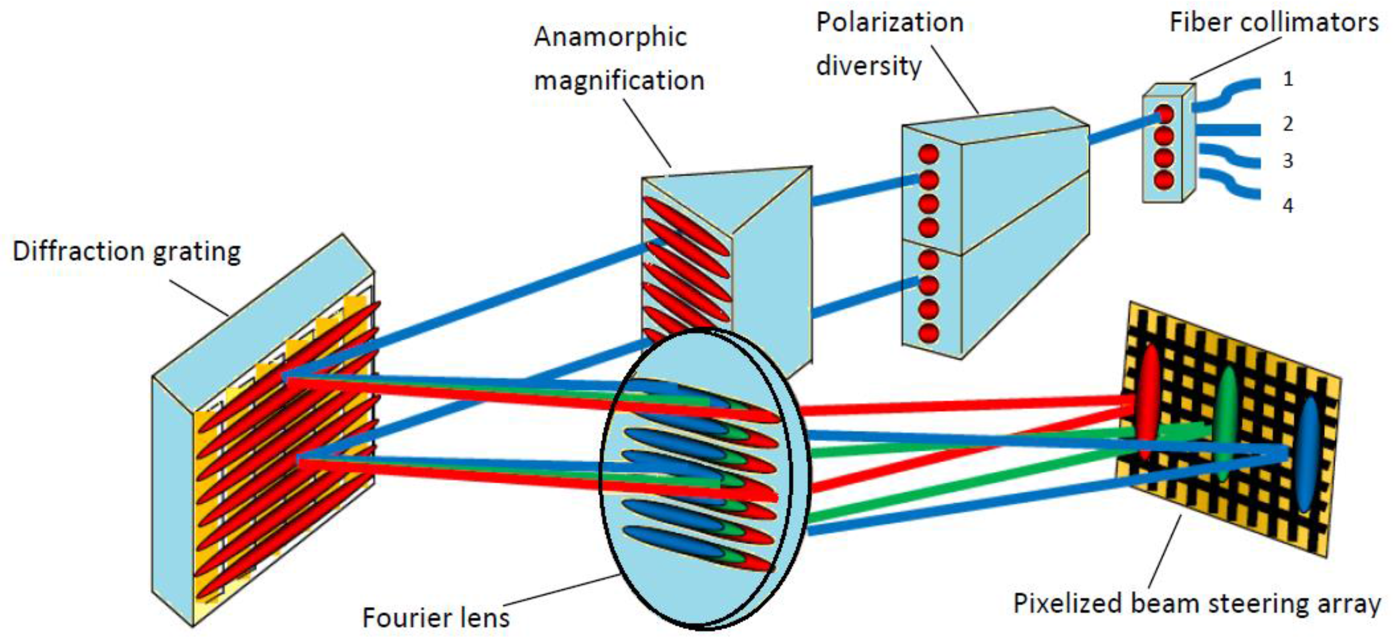
A schematic drawing of the WSS is shown to the reader in Figure 1. The spectral elements of a dense wavelength multiplexing signal from one input fiber are switched to multiple output ports by the phase grating written on the LCoS.
The input port is labeled 1, and the output ports are labeled 2, 3, and 4 separately. Light coming from the input fiber first goes though polarization diversity optics and separates into two co-polarized beams. The anamorphic optics expand the beam into an elliptical beam spot. The input light is then spread by a dispersive element (gratings) into angularly separated wavelengths. Then the angular separation is transformed to spatial separation by the Fourier lens. The collimated light is then modulated by the phase grating on the LCoS display. Different wavelengths are projected into different parts of the LCoS display, as shown in Figure 1. The diffraction grating again recombines all different wavelength diffracted by the LCoS onto individual output ports. In this way, different wavelengths are being selectively routed to any selected output ports.
The crosstalk [42] is the light intensity leaked to the non-selected output port; in other words, the lights diffracted to other orders, except the first order, and coupled into the non-selected output ports are considered as crosstalk for the system.
Crosstalk can be divided into two levels; the device and the system level. On the device level, the crosstalk is closely related to the diffraction efficiency of the blazed grating written on the LCoS. Due to the imperfection of the hologram on the LCoS, higher orders are unintentionally coupled to the output ports. On the system level, the crosstalk is related to the coupling characteristic of the optical components, such as output fiber position, lens aperture, field spot on the LCoS, grating pitch, and so on. In order to reduce the crosstalk, the coupling efficiency for higher (m ≠ 1) diffraction orders should be low. Table 2 is an overview of the classification of crosstalk, more detailed study on this part is provided in the following section with experimentally verification on the GAEA device.
2.2.1. Device Level Crosstalk
The LCoS SLMs can only display a quantized phase and spatial profile, approximating an ideal blazed grating due to the finite pixel size (spatial quantization) and due to the limited available phase values (phase quantization). Higher orders (m ≠ 1) are generated and unintentionally coupled to other output positions, which is denoted as static crosstalk. Not only the quantization of phase and pixel, but also other physical effects such as fringing field effect, phase flicker, and device non-uniformity, would induce an error in the phase profile. Such deviation from an ideal blazed grating would thus generate higher orders, i.e., static crosstalk.
Another kind of crosstalk occurring only during switching is called transient crosstalk [43,44]. During switching, the phase pattern is not controlled intentionally; thus for a short time period, the transiently generated diffraction orders will be coupled to other output ports. Mitigation approaches have been proposed, such as inserting an intermediate phase pattern with an un-periodic pattern between the start and end gratings of the switching process or using the complex addressing sequence during the switching [45]. These approaches address the fundamental cause of the transient crosstalk by disturbing the periodic phase structure so that the light is randomly scattered instead of diffracted during switching
In order to fully understand where the static crosstalk comes from and how it could be reduced, the LCoS device, GAEA from Holoeye [46] (10 megapixels resolution, pixel size 3.74 µm, digitally addressed backplane), is studied, calibrated for wavelength 1550 nm (with default voltage setting for the low and high electrode levels to be 0.5 and 1.5 volts). Below, two physical phenomena, phase flicker and fringing field effect, are illustrated and their relations with device level crosstalk are discussed.
Phase Flicker
A digital pulse width modulation scheme is used in current displays as the driving sequence for representing different gray levels [47,48]. Due to the finite viscosity of the LC molecules, the time-averaged voltage is observable for LC molecules, which is related to phase representation; however, the superimposed pulse modulation pattern produces certain fluctuation in the orientation of the LC molecules, which leads to the flicker [49] on the beam of light. This effect could be detrimental for images as the gray level is drifting around the desired value; thus such uncertainty could reduce the diffraction efficiency of gratings [50]. By using a higher frequency for the driving sequence, the flicker amplitude can be reasonably reduced, which is also demonstrated by Martínez et al. for visible bandwidth [51].
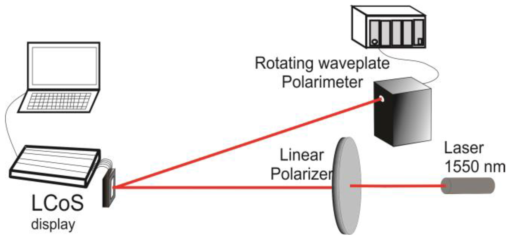
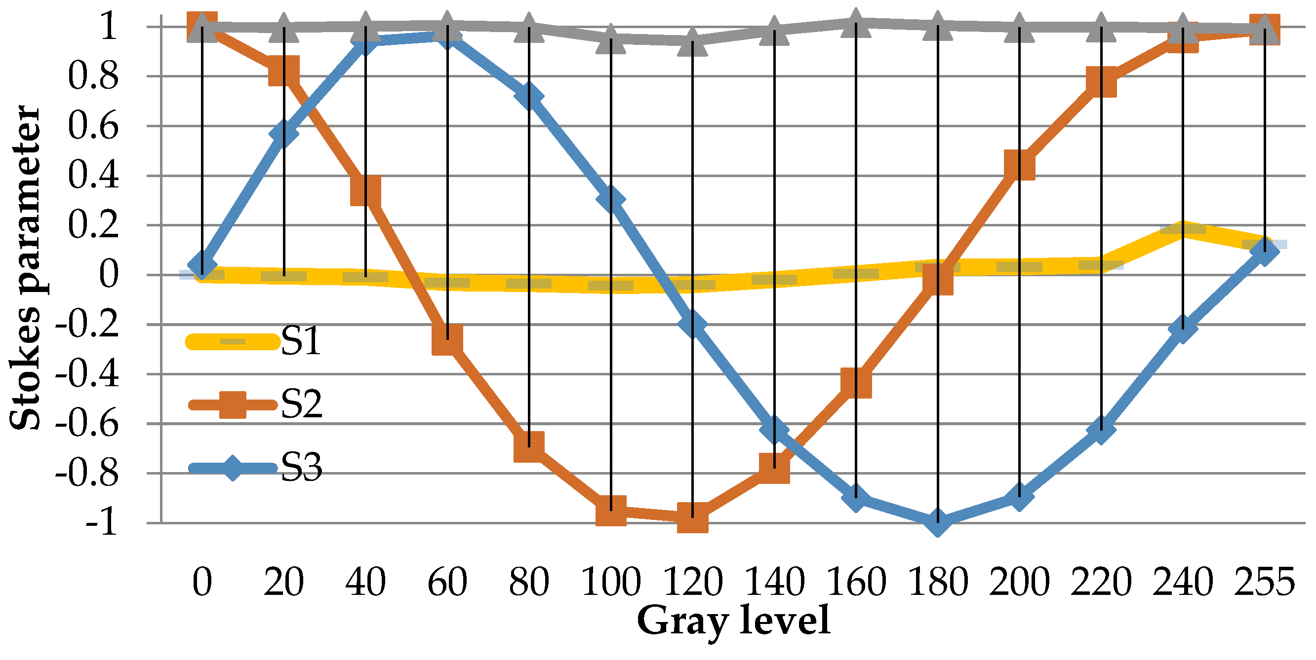
Figure 2 shows the experimental setup for flicker measurement, in which linearly polarized light vibrating at 45° with respect to the LC director (the LC director is parallel to the long axis of the display for GAEA device) impinges perpendicularly onto the entrance window of the device. Different gray levels are addressed to the display under the default voltage setting (the low and high voltages on the electrode are 0.5 and 1.5 volts, respectively, enabled by the control software of the GAEA device). The state of polarization (SOP) of the reflected light is measured with a Stokes polarimeter, which provides the time-averaged stokes parameters for a time interval longer than the characteristic flicker period. In Figure 3 and Figure 4, we show the experimental results obtained for the GAEA by applying the averaged Stokes polarimetric technique demonstrated in [52,53].
This averaged Stokes polarimetric technique is described as follows; the GAEA device is a parallel-aligned LCoS device (PA-LCoS), thus it can be considered equivalent to a variable linear retarder, the retardance of which varies as a function of the applied voltage (gray level). This algorithm for the retardance calculation is based on Mueller-Stokes formalism and models the linear variable retarder including retardance instabilities (flicker), wherein the fluctuation of retardance (flicker) is approximated as a triangular time-dependent profile. By measuring the Stokes parameters (SOPs) for the input and output light and for all grey levels displayed on the device, the retardance and flicker parameters can be obtained by fitting the theoretical expressions and experimental values for each gray level. Figure 3 is the measurement result for the Stokes parameters of the output reflected light. S1, S2, and S3 are the measured stokes parameters of the output light versus the gray level. DoP is short for ‘degree of polarization’, which denotes how much light is polarized.
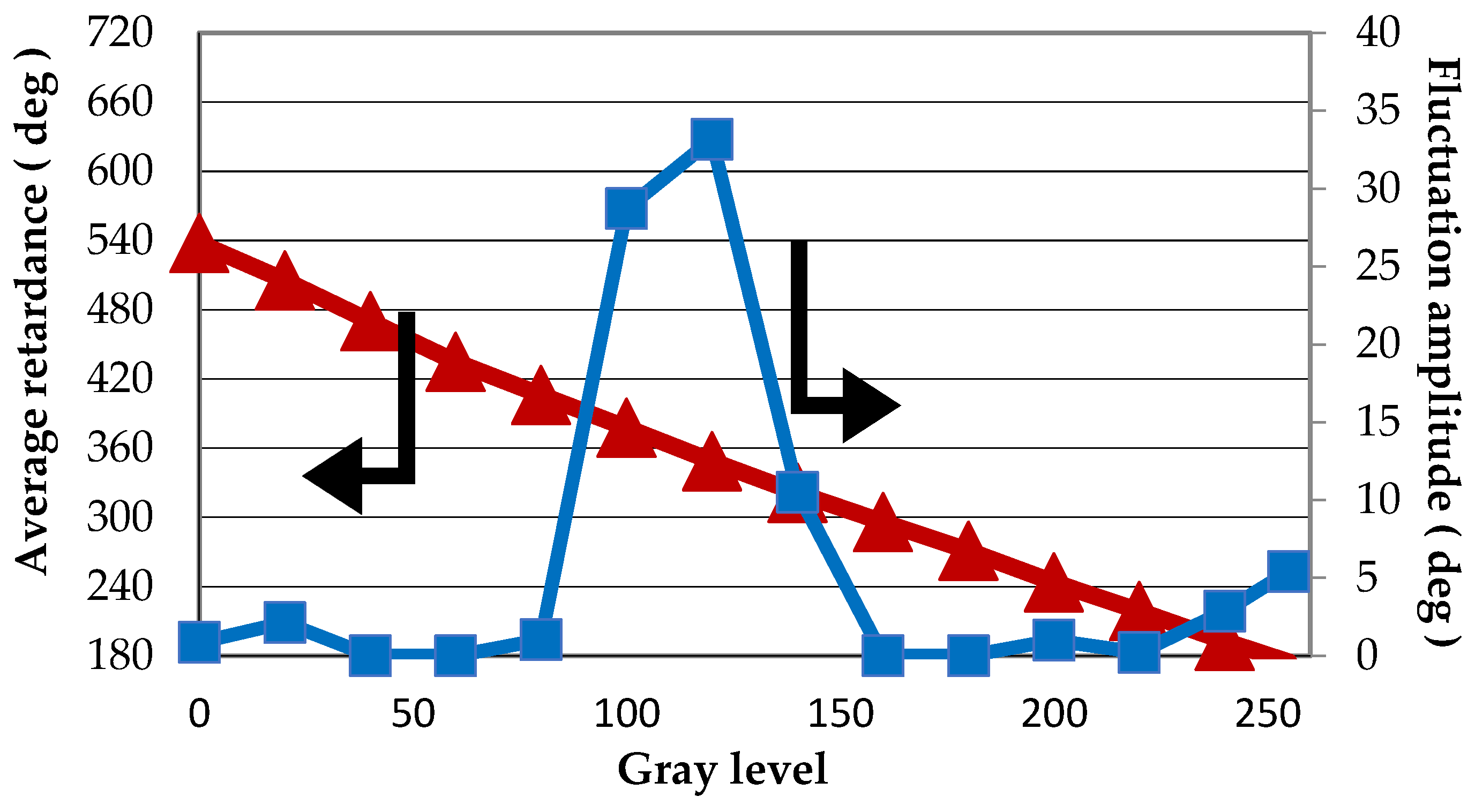
Average retandance as a function of the gray level (i.e., the calibrated look-up table (LUT) of the GAEA device) is calculated by the above mentioned method and is plotted in Figure 4. The LUT provides the information with which the gray level must be addressed to the screen so that the desired phase value is written onto the incident light wavefront. From Figure 4, we see that the presented LUT of the GAEA device is quite linear, which indicates that the device is being well calibrated under the default voltage setting. The flicker value is different for each grey level and the maximum flicker is about 35° for gray level 120.
One way of reducing the flicker is to lower the temperature of the LCoS device. It has been proved that a reduction of up to 80% of the flicker is possible when the LCoS is brought to −8 °C [54]. Therefore, temperature control electronics can be added to the backplane of the SLM to decrease as well as stabilize the operating temperature so the impact of temperature drift is minimized.
Fringing Field Effect
When the pixel spacing is smaller than the thickness of the LC layer, the electric field is no longer homogeneous over a pixel. Due to the inhomogeneous distribution of the electrical field across a single pixel, the phase response is also not constant upon a pixel. Several researchers have illustrated this fringing field effect [55], which is considered the main limitation to LCoS performance. A width/height ratio, τE, is used as an indicator of how strong the fringing field is. It is defined in Equation (2), where W is the width of the electrode and d is the LC cell thickness:
In one simplified model of the fringing field effect by Uzi Efron [56], where the amplitude modulation is almost ignored in the modeling, the blazed grating diffraction efficiency is given quantitatively by:
where η is the blazed grating diffraction efficiency, Λ is the length of the grating period, and ∆XFB is the fly-back zone width, which is defined as the broadening width of the phase profile, particularly in areas of sharp spatial transition such as blaze resets. This equation is widely used for fast calculation of the expected diffraction efficiency. In another model built by Lu et al. [57], the near field phase profile of the grating is observed under a microscope. The profile is then fitted using the error function, and the diffraction efficiency is calculated by the angular spectrum method. This method provides a way of diffraction efficiency optimization based on the near field phase profile optimization instead of the much more typical far field optimization algorithm related to a computer generated hologram (CGH) [58,59,60]. The near field optimization method provides a more direct and accurate measurement. Similar near field approaches [61] are also proposed by measuring the sub-pixel Jones matrices and modeling the fringing field effect as a low pass filter.
In order to compensate for the diffraction efficiency reduction of the blazed grating due to the fringing field effect, a voltage profile optimization method has been verified using rigorous numerical simulation software for liquid crystal devices by X. Wang et al. [62,63]. Especially for small pixel devices, the deformation of the phase profile is huge compared with that of ideal blazed grating in the phase reset region. As we can see from the simulation result by X. Wang et al, the efficient modulation depth for a blazed grating is not able to achieve 2π when using the LUT obtained for the uniform screen due to the fringing field effect. Thus, optimization of the diffraction efficiency could only be done by changing the voltage applied to the electrodes. By changing the voltage of each pixel in a blazed grating iteratively, the phase value on each electrode could be adjusted to be similar to that of the desired phase profile. He also analyzed the relationship between the fringing field effect and various parameters given by rigorous simulation such as pixel size, cell thickness, the electrode spacing, the voltage profile, the gap between electrodes, the birefringence of the LC material, the pretilt angle, the elastic constants, and the surface alignment direction. As shown by the simulation result, a high birefringence material is critical for wide-angle LC optical phase array for better performance regarding the diffraction efficiency. Experimental verification of the voltage optimization method has also been performed. In one study by E. Haellstig [64], a LC SLM with 1 × 4096 small stripe shaped pixels (1.8 µm) was studied. By using the voltage profile optimization method, the diffraction efficiency could be improved significantly.
We would like to see whether this voltage optimization method for the diffraction efficiency of blazed gratings would be useful for the GAEA we have. Further experimental verification is done and presented in the following. In the case of diffraction efficiency measurements, we use a slightly modified version of the experimental setup in Figure 2, where a lens is added at the output of the LCoS to focalize the diffracted orders on the lens focal plane. Light incidents perpendicularly to the GAEA device. The input light is linearly polarized parallel to the LC director. We display blazed gratings with different numbers of pixels per period, each pixel corresponding to a phase level. The first order diffracted intensity is measured with a power meter. This data is presented as the original blazed grating in Figure 5. We then apply the voltage optimization method. After voltage optimization, the first order diffracted light of the blazed gratings is measured again, and we can see that the diffraction efficiency increases dramatically, especially for the small period gratings (large diffraction angel). The measurement data is plotted in Figure 5 as a function of the diffraction angle, calculated with the grating equation [65], where Λ is the grating period, λ is the wavelength in use, and θ is the diffracted angle.
As we can see from Figure 5, the above-mentioned voltage optimization method is proven to be effective for integer periods of blazed gratings, especially for LCoS with small period sizes (large diffraction angle). Without considering other factors such as the output fiber position, the pure crosstalk generated by the LCoS device is represented by the diffraction efficiency of other higher orders. Thus, higher diffraction efficiency for first order diffracted light also indicates a lower diffraction efficiency for other orders, i.e., lower crosstalk for the system. As we can see, the diffraction efficiency for the optimized grating increases with respect to the non-optimized as the diffraction angle increases; this indicates that the crosstalk is reduced compared with original result.
For non-integer periods of blazed grating, due to the inherent large crosstalk induced by the grating structure itself (even by the ideal phase profile), although the voltage optimization method is proved to be effective, the crosstalk between different channels is still relatively high.
For next generation high resolution displays, it is desired not to have ‘crosstalk’ between pixels, i.e., no fringing field effect. Thus, methods have come up by, for example, inserting a polymer wall between pixels (15 µm pixel size is demonstrated [66]) or having three electrodes in one pixel to generate a homogenous electric field [67].
2.2.2. System Level Crosstalk
Given the LCoS device we have (with a certain amount of fringing field effect), there are several other parameters related to the whole WSS system in the crosstalk estimation, such as output fiber positions, lens aperture, field spot on the LCoS, and grating pitch. The strategy of reducing system level crosstalk takes advantage of the inefficient coupling of higher diffraction orders to the output ports.
One approach makes use of computer-generated holograms (CGH) by utilizing the programmable feature of the device [68,69,70]. It is by rapidly calculating the phase of the wave function to be displayed onto the LCoS when the intensity distribution in the diffraction plane is known. The CGH is able to route light with predictable location and intensity for each diffraction order [71]. Thus, by calculating the location of the signal and other orders carefully, it becomes more manageable to define the output fiber position in order to achieve less crosstalk. The Cambridge group combines Gerchberg-Saxton algorithm and a simulated annealing routine to further reduce the crosstalk between different channels to <−40 dB and achieves a uniform signal insertion loss for all ports [68].
Similar approaches are proposed, such as wave front encoding, in which a diffractive lens is written on the SLM. Certain defocusing of the lens could ensure that only one preferred diffraction order is optimally coupled into the fiber; thus the crosstalk between different channels could be reduced [72].
Pulse shaping is another widely used technique for crosstalk reduction in optical systems. The relatively long ‘tails’ of a Gaussian passband leads to accumulated crosstalk; however a flat passband has greater wavelength misalignment tolerance and better cascadability. Thus, pulse shaping of the beam coupled from the fiber would be a preferred solution. Examples are given, such as changing the fiber end to alter the coupling characteristics [73] and the Multi-Plane Light Conversion method proposed by Bell lab [74].
Other approaches to crosstalk reduction, such as filtering out higher diffraction orders [75], have also been reported.
2.3. Insertion Loss
The insertion loss is the loss between the input and output ports, which should be uniform over all input-output connections. As with crosstalk, the insertion loss is also related to multiple parameters, such as the polarization and phase modulation of the device, reflectance of LCoS, output fiber position, and the coupling characteristics of the fiber.
In this section, we would like to focus on one physical effect which is mainly related to smaller pixel devices, i.e., the fringing electric field effect.
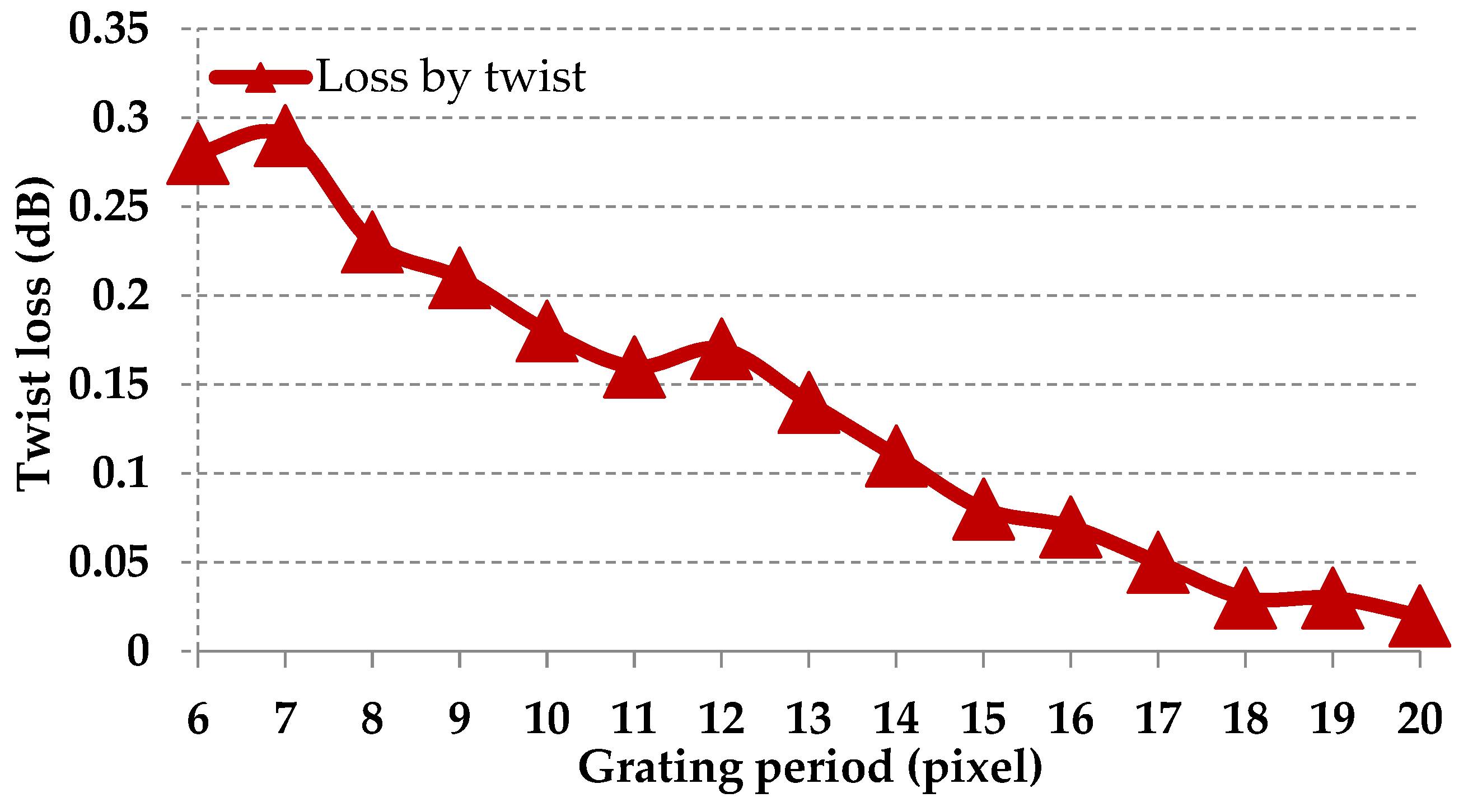
The fringing electric field effect is quite obvious with small pixel size devices when horizontal gratings are written on the device (light is diffracted vertically). Due to the electric fringing field caused by the difference of the voltages applied to the neighboring pixels, the liquid crystal molecule is forced to rotate in the x–y plane (LC rotates in x–z plane for grey level representation); thus, the output light is being polarization modulated. Such a twist, induced by the applied electrical field, will on one hand minimize the fly-back region and, on the other hand, introduce losses for the WSS system when one polarizing beam combiner (PBC) is used at the output to recombine two polarizations together. Due to the nature of the twist, which is related to the voltage setting, its effect could be slightly reduced by lowering the voltage applied to the LC layer. Such polarization and intensity modulation characteristics of LC gratings have been extensively studied by He et al. and Scott Harris [76,77].
We experimentally verify this effect. As in the experimental setup in Figure 2, horizontal gratings are written on the SLM, with the help of the Stokes polarimeter, we measure the SOP for the diffracted light. The incident light is linearly polarized along the director axis of the LCoS; however the output light is not polarized along the LC director axis. Thus, we conclude that the SOP for the input light is being polarization modulated. In fact, the result of the polarimeter shows that the diffracted beam is elliptically polarized. It is unusual that the diffracted light is being polarization modulated for a phase-only SLM. We would like to know how much loss is induced by this effect to the whole WSS system. We put an output polarizer (transmission axis parallel to the one of the input polarizer) in the reflected path, replace the polarimeter once again for the power meter, and further calculate the loss of the transition with and without the output polarizer.
As we can see from Figure 6, the losses for different grating periods are also different, which indicates the non-uniformity of the loss for different output ports. From Figure 6, we could conclude that the loss increases when the grating period decreases. It would be possible to program the phase pattern so that the output signals are attenuated to achieve a uniformity of loss.
3. The Trend of LCoS Device for Future WSS Module
Although the WSS based on LCoS devices has been researched for long time [78,79], the requirements on the WSS system [80,81,82,83,84,85] have evolved rapidly in recent years. In the following, we briefly introduce the development of WSS in recent years. Functions such as flex gird, M × N WSS, the combination of WSS with SDM systems, and so on are being demonstrated. Flex grid is considered to be the main feature for next generation networks. The traditional standard Telecommunication Standardization Sector of the International Telecommunications Union (ITU-T) grid with fixed spacing (i.e., 50 GHz) induces an inefficient use of the optical spectra and limits the transmission capacity. The flex grid allows different modulation formats to coexist and be efficiently and densely multiplexed, thus helps to extend the reach and per channel bit rate of future optical networks. M × N WSS has been demonstrated in past years by LCoS devices. Although 1 × N WSS is widely used in the deployment of ROADM, M × N WSS serves as another option for future metro-traffic trends [86], which provides flexibility for complex mesh optical networks [81]. In future networks, further extending of the capacity could be solved by space division multiplexing (SDM). Thus, combining WSS with SDM would be quite promising to achieve economic viability [87].
Based on the result we have for the GAEA device, we propose or explain more possible optimization directions for WSS development.
3.1. Faster LCoS Response for Faster WSS Switching
In Section 2.1, we have shown that zero twisted ECB is advantageous for phase only modulation with its response time on the scale of 10–100 ms. However, faster response is demanding in lots of applications. The researchers are continuously exploring new materials or ways to generate a faster response time. Below is a brief discussion of the recent achievements.
The development of faster response LC materials such as Blue-Phase liquid crystal proposed by the University of Central Florida [88], is demonstrated to be of high potential for its use in SLM with the function of polarization insensitive modulation. The direction of future research into this kind of LC material would be to lower the operation voltage, reduce hysteresis, and improve properties such as stability and contrast [89,90]. Other approaches for example beam steering with liquid crystal phase grating is also able to achieve faster response (<10 ms) and adjustable switching angles. This phase grating is made of fringe field switching (FFS) liquid crystal (LC) cells. It serves an alternative way of beam steering functions [91].
3.2. Higher Reflectivity of the LCoS Front Cover Plate for Lower WSS Loss
The reflection loss is quite large for LCoS designed for telecomm applications. For example, the reflectivity of the GAEA device is about 72% with a 4% fluctuation due to the interference effect in the multilayer structure. With an antireflection coating on the backplane, the pure reflectivity could be improved by about 6%. However a higher driving voltage may be required in order to have the same modulation depth.
3.3. Smaller LCoS Pixel Size for Higher Number of WSS Ports Counts
A WSS with more output ports [92] is quite demanding, which helps to handle a large number of channels as well as provide a simple system configuration. Methods [93,94,95] are proposed by using a planar lightwave circuit (PLC) as spot size converter to decrease the physical size of the spot or by using a Bragg reflector waveguide with a high deflection angle (small waveguide spacing or pitch size). The principle behind these methods is illustrated by the following equation.
The maximum port-count based on LCoS can be calculated by Equation (5):
where θmax is the maximum deflection angle of LCoS, which is roughly ±1° in common designs; f is the focal length; and Parray is the pitch of the waveguide array.
Nport = θmax × f/Parray,
As we can see from Equation (5), high deflection angle corresponds to more port-counts. Smaller pixel sized LCoS also help to achieve more output ports. If we compare gratings composed of same number of pixels in a period, the pitch of the grating (d) for smaller pixel devices is also smaller. As we can see from Equation (4), the diffraction angle is thus bigger when the pitch is smaller. Together with Equation (5), we could conclude that smaller pixel devices would provide more ports.
However, as we discussed in the above sections, the pixel size is not only related to the maximum number of the output ports; it is also related with other physical effects such as the fringing field effect, the fringing electric field effect, and so on. All these physical effects are detrimental to the performance of the whole system. Thus, it is desirable to make a trade-off of all these factors due to the requirement of the system and choose the proper pixel size.
4. Discussion and Conclusions
In this paper, we have studied the LCoS SLM for the WSS application. We have investigated the fundamental physics of LCoS, which affect three important parameters; response time, crosstalk, and insertion loss. The response time of the device is mainly related to the LC material and the driver electronics. Crosstalk is caused by various effects from the LCoS device and from the whole WSS system point of view. An important method to mitigate crosstalk is CGH; however its performance is limited by the specification of the device itself. The insertion loss comes from the insertion loss of the fiber, reflection loss, and loss induced by polarization modulation. All these specifications are experimentally and theoretically studied in this paper based on 10 megapixels LCoS, the GAEA device. In order to have the optimal performance of the whole system, all the physical effects should be taken into account and need to be balanced with each other.
To fulfill the future requirements of the WSS system, the LCoS needs to be further optimized, by developing new LC materials and a smarter driving board for faster response time, implementing higher resolution (e.g., 8 K) for a higher number of ports, building polymer walls between pixels for suppressing crosstalk, etc.
Compared with micro-electromechanical systems (MEMS) based WSS, although the LCoS based WSS has disadvantages of insertion loss, switching speeds, polarization dependent loss, wavelength range, and the number of ports, it is more advantageous in terms of phase modulation capability and programmable features. Therefore the WSS based LCoS could be considered very promising in the future.
Acknowledgment
This work has been supported by the EC through H2020 project ROAM (Grant No. 645361 www.roam-project.eu).
Author Contributions
The authors contributed almost equally to the paper. Mi Wang wrote the paper; Liangjia Zong, Mao Lei, Andres Marquez, and Mi Wang conceived and designed the experiments in the paper; Mao Lei and Han Zhao performed the experiments and analyzed the data; Francisco Javier Vaquero Caballero and Yabin Ye contributed analysis tools.
Conflicts of Interest
The authors declare no conflict of interest.
References
- Bleha, W.P.; Lei, L.A. Advances in liquid crystal on silicon (LCoS) spatial light modulator technology. SPIE Def. Secur. Sens. Int. Soc. Opt. Photonics 2013. [Google Scholar] [CrossRef]
- Hermerschmidt, A.; Lazarev, G.; Rozhkov, O.V. LC-based Phase-modulating Spatial Light Modulators. In Proceedings of the Digital Holography and Three-Dimensional Imaging, Seattle, WA, USA, 13–17 July 2014. [Google Scholar]
- Turunen, J.; Wyrowski, F. (Eds.) Diffractive Optics for Industrial and Commercial Applications; John Wiley & Sons: Hoboken, NJ, USA, 1997. [Google Scholar]
- Coufal, H.; Psaltis, D.; Sincerbox, G. Holographic Data Storage. In Springer Series in Optical Sciences; Springer: Berlin/Heidelberg, Germany, 2000; Volume 76. [Google Scholar]
- Osten, W.; Kohler, C.; Liesener, J. Evaluation and application of spatial light modulators for optical metrology. Opt. Pura Apl. 2005, 38, 71–81. [Google Scholar]
- Roelens, M.A.; Frisken, S.; Bolger, J.A.; Abakoumov, D.; Baxter, G.; Poole, S.; Eggleton, B.J. Dispersion trimming in a reconfigurable wavelength selective switch. J. Light. Technol. 2008, 26, 73–78. [Google Scholar] [CrossRef]
- Salsi, M.; Koebele, C.; Sperti, D.; Tran, P.; Mardoyan, H.; Brindel, P.; Bigo, S.; Boutin, A.; Verluise, F.; Sillard, P. Mode-Divison Multiplexing of 2100 Gb/s Channels Using an LCOS-Based Spatial Modulator. J. Light. Technol. 2012, 30, 618–623. [Google Scholar] [CrossRef]
- Solís-Prosser, M.; Arias, A.; Varga, J.; Rebón, L.; Ledesma, S.; Iemmi, C.; Neves, L. Preparing arbitrary pure states of spatial qudits with a single phase-only spatial light modulator. Opt. Lett. 2013, 38, 4762–4765. [Google Scholar] [CrossRef] [PubMed]
- Schröder, J.; Roelens, M.A.; Du, L.B.; Lowery, A.J.; Eggleton, B.J. LCOS based waveshaper technology for optical signal processing and performance monitoring. In Proceedings of the 17th Opto-Electronics and Communications Conference (OECC), Busan, Korea, 2–6 July 2012. [Google Scholar]
- Wu, S.T.; Yang, D.K. Reflective Liquid Crystal Displays; John Wiley & Sons Inc.: Chichester, UK, 2005. [Google Scholar]
- Davey, N.C.T.; Chrstmas, J.; Chu, D.; Crossland, B. The Applications and Technology for Phase-Only Liquid Crystal on Silicon Devices. J. Disp. Technol. 2011, 7, 112–119. [Google Scholar]
- Keyworth, B.P. ROADM subsystems and technologies. In Proceedings of the Optical Fiber Communication Conference and Exposition (OFC/NFOEC), Anaheim, CA, USA, 6-11 March .2005; pp. 1–4. [Google Scholar]
- Strasser, T.A.; Wagener, J.L. Wavelength-Selective Switches for ROADM Applications. IEEE J. Sel. Top. Quantum Electron. 2010, 16, 1150–1157. [Google Scholar]
- De Hennin, S.; Wall, P.; Moffat, S.H.; Keyworth, B.P.; Colbourne, P.D. Addressing Manufacturability and Reliability of MEMS-based WSS. In Proceedings of the OFC/NFOE Conference on Optical Fiber Communication and the National Fiber Optic Engineers Conference, Anaheim, CA, USA, 25–29 March 2007. [Google Scholar]
- Chu, T.; Yamada, H.; Ishida, S.; Arakawa, Y. Compact 1 × N thermo-optic switches based on silicon photonic wire waveguides. Opt. Express 2005, 13, 10109–10114. [Google Scholar] [CrossRef] [PubMed]
- Cheng, Q.; Wonfor, A.; Penty, R.V.; White, I.H. Scalable, low-energy hybrid photonic space switch. J. Light. Technol. 2013, 31, 3077–3084. [Google Scholar] [CrossRef]
- Shiraiwa, M.; Furukawa, H.; Miyazawa, T.; Awaji, Y.; Wada, N. High-Speed Wavelength Resource Reconfiguration System Concurrently Establishing/Removing Multi-wavelength Signals. IEEE Photonics J. 2016, 8, 1–7. [Google Scholar]
- Frisken, S.; Baxter, G.; Abakoumov, D.; Zhou, H.; Clarke, I.; Poole, S. Flexible and grid-less wavelength selective switch using LCOS technology. In Proceedings of the Optical Fiber Communication Conference and Exposition (OFC/NFOEC), Los Angeles, CA, USA, 6–10 March 2011; pp. 1–3. [Google Scholar]
- Finisar Application Note, Group Delay Ripple Compensation. Available online: https://www.finisar.com/sites/default/files/resources/an_waveshaper_group_delay_ripple_compensation.pdf (accessed on 23 March 2017).
- Pulikkaseril, C.; Stewart, L.A.; Roelens, M.A.F.; Baxter, G.W.; Poole, S.; Frisken, S. Spectral Modeling of Channel Band Shapes in Wavelength Selective Switches. Opt. Express 2011, 19, 8458–8470. [Google Scholar] [CrossRef] [PubMed]
- He, J.; Norwood, R.A.; Brandt-Pearce, M.; Djordjevic, I.B.; Cvijetic, M.; Subramaniam, S.; Himmelhuber, R.; Reynolds, C.; Blanche, P.; Lynn, B.; et al. A survey on recent advances in optical communications. Comput. Electr. Eng. 2014, 40, 216–240. [Google Scholar]
- Collings, N.; Davey, T.; Christmas, J.; Chu, D.P.; Crossland, B. The applications and technology of phase-only liquid crystal on silicon devices. J. Disp. Technol. 2011, 7, 112–119. [Google Scholar]
- Wilkinson, T.D.; Henderson, C.D.; Leyva, D.G.; Crossland, W.A. Phase modulation with the next generation of liquid crystal over silicon technology. J. Mater. Chem. 2006, 16, 3359–3365. [Google Scholar] [CrossRef]
- Zhang, P.; Tan, Y.; Liu, W.; Chen, W. Methods for optical pahse retardation measurement: A review. Sci. China Technol. Sci. 2013, 56, 1155–1164. [Google Scholar] [CrossRef]
- Zhang, Z.C.; Yang, H.N.; Robertson, B.; Redmond, M.; Pivnenko, M.; Collings, N.; Crossland, W.A.; Chu, D. Diffraction based phase compensation method for phase-only liquid crystal on silicon devices in operation. Appl. Opt. 2012, 51, 3837–3846. [Google Scholar] [PubMed]
- Engstrom, D.; Persson, M.; Bengtsson, J.; Goksor, M. Calibration of spatial light modulators suffering from spatially varying phase response. Opt. Express 2013, 21, 16086–16103. [Google Scholar] [PubMed]
- Reichelt, S. Spatially resolved phase-response calibration of liquid-crystal-based spatial light modulators. Appl. Opt. 2013, 52, 2610–2618. [Google Scholar] [CrossRef] [PubMed]
- Bone, M.; Coates, D.; Crossland, W.; Gunn, P.; Ross, P. Ferroelectric liquid crystal display capable of video line address times. Displays 1987, 8, 115–118. [Google Scholar] [CrossRef]
- Handschy, M.; Johnson, K.; Moddel, G.; Pagano-Stauffer, L. Electro-optic applications of ferroelectric liquid crystals to optical computing. Ferroelectrics 1988, 85, 279–289. [Google Scholar] [CrossRef]
- Grigory, L.; Andreas, H.; Sven, K.; Osten, S. 1. LCOS Spatial Light Modulators: Trends and Applications. In Optical Imaging & Metrology Advanced Technologies; John Wiley & Sons: Hoboken, NJ, USA, 2012; pp. 1–29. [Google Scholar]
- Stamm, S.; Riethoven, J.J.; Le Texier, V.; Gopalakrishnan, C.; Kumanduri, V.; Tang, Y.; Barbosa-Morais, N.L.; Thanaraj, T.A. ASD: A bioinformatics resource on alternative slicing. Nucleic Acids Res. 2006, 34, D46–D55. [Google Scholar] [PubMed]
- McKnight, D.J.; Vass, D.G.; Sillitto, R.M. Development of a spatial light modulator: A randomly addressed liquid crystal over nMOS array. Appl. Opt. 1989, 28, 4757–4762. [Google Scholar] [CrossRef] [PubMed]
- Soref, R.A.; Rafuse, M.J. Electrically controlled birefringence of thin nematic films. J. Appl. Phys. 1972, 43, 2029–2037. [Google Scholar] [CrossRef]
- Labrunie, G.; Robert, J. Transient behavior of the electrically controlled birefringence in a nematic liquid crystal. J. Appl. Phys. 1973, 44, 4869–4874. [Google Scholar]
- Armitage, D.; Kinell, D.K. Miniature spatial light modulators. Proc. SPIE 1990, 1296, 158–165. [Google Scholar]
- Buckley, E. Holographic laser projection. J. Disp. Technol. 2011, 7, 135–140. [Google Scholar]
- Dasgupta, P.; Das, M.K.; Das, B. Physical properties of three liquid crystals with negative dielectric anisotropy from X-ray diffraction and optical birefringence measurements. Mol. Cryst. Liq. Cryst. 2011, 540, 154–161. [Google Scholar]
- Cotter, L.K.; Drabik, T.J.; Dillon, R.J.; Handschy, M.A. Ferroelectric-liquid-crystal/silicon-integrated circuit spatial light modulator. Opt. Lett. 1990, 15, 291–293. [Google Scholar] [PubMed]
- Armitage, D.; Kinell, D.K. Liquid crystal integrated silicon spatial light modulator. Appl. Opt. 1992, 31, 3945–3949. [Google Scholar] [CrossRef] [PubMed]
- Wang, H.; Nie, X.; Wu, T.X.; Wu, S.T. Cell gap effect on the dynamics of liquid crystal phase modulators. Mol. Cryst. Liq. Cryst. 2005. [Google Scholar] [CrossRef]
- Hyman, R.M.; Lorenz, A.; Morris, S.M.; Wilkinson, T.D. Polarization-independent phase modulation using a blue-phase liquid crystal over silicon device. Appl. Opt. 2014, 53, 6925–6929. [Google Scholar] [CrossRef] [PubMed]
- Leyva, D.G.; Robertson, B.; Henderson, C.J.; Wilkinson, T.D.; O’Brien, D.C.; Faulkner, G. Cross-talk analysis in a telecentric adaptive free-space optical relay based on a spatial light modulator. Appl. Opt. 2006, 45, 63–75. [Google Scholar]
- Yang, H.; Robertson, B.; Chu, D. Transient crosstalk in LCOS based WSS and a method to suppress the crosstalk levels. In Proceedings of the Optical Fiber Communication Conference and Exposition and the National Fiber Optic Engineers Conference (OFC/NFOEC), Anaheim, CA, USA, 17–21 March 2013. [Google Scholar]
- Yang, H.; Robertson, B.; Yu, D.; Zhang, Z.; Chu, D. Origin of transient crosstalk and its reduction in phase-only LCOS wavelength selective switches. J. Light. Technol. 2013, 31, 3822–3829. [Google Scholar] [CrossRef]
- Kaminow, I.; Li, T.; Willner, A.E. Technology and application of liquid crystal on silicon (LCoS) in telecommunications. In Optical Fiber Telecommunications Volume VIA: Components and Subsystems; Academic Press: New York, NY, USA, 2013. [Google Scholar]
- HOLOEYEs SLMs. Available online: www.holoeye.com (accessed on 20 March 2017).
- Noguchi, K.; Sakano, T.; Matsumoto, T. A rearrangeable multichannel free-space optical switch based on multistage network configuration. J. Light. Technol. 1991, 9, 1726–1732. [Google Scholar] [CrossRef]
- Mora, M.C.; Minguez, A.M.; Horche, P.R. Design of equalized ROADMs devices with flexible bandwidth based on LCoS technology. In Proceedings of the 19th European Conference on Networks and Optical Communications-(NOC), Milano, Italy, 4–6 June 2014; pp. 41–46. [Google Scholar]
- Hermerschmidt, A.; Osten, S.; Krüger, S.; Blümel, T. Wave front generation using a phase-only modulating liquid-crystal-based micro-display with HDTV resolution. In Proceedings of the International Congress on Optics and Optoelectronics, International Society for Optics and Photonics, Prague, Czech Republic, 16 April 2007. [Google Scholar]
- Martínez, F.J.; Márquez, A.; Gallego, S.; Ortuño, M.; Francés, J.; Pascual, I.; Beléndez, A. Predictive capability of average Stokes polarimetry for simulation of phase multilevel elements onto LCoS devices. Appl. Opt. 2015, 54, 1379–1386. [Google Scholar] [CrossRef] [PubMed]
- Martínez, F.J.; Márquez, A.; Gallego, S.; Francés, J.; Pascual, I.; Beléndez, A. Extended linear polarimeter to measure retardance and flicker: Application to liquid crystal on silicon devices in two working geometries. Opt. Eng. 2014, 53, 014105. [Google Scholar]
- Martínez, F.J.; Márquez, A.; Gallego, S.; Francés, J.; Pascual, I.; Beléndez, A. Retardance and flicker modeling and characterization of electro-optic linear retarders by averaged Stokes polarimetry. Opt. Lett. 2014, 39, 1011–1014. [Google Scholar] [CrossRef] [PubMed]
- Martínez, F.J.; Márquez, A.; Gallego, S.; Ortuño, M.; Francés, J.; Beléndez, A.; Pascual, I. Averaged Stokes polarimetry applied to evaluate retardance and flicker in PA-LCoS devices. Opt. Express 2014, 22, 15064–15074. [Google Scholar] [PubMed]
- García-Márquez, J.; López, V.; González-Vega, A.; Noé, E. Flicker minimization in an LCoS spatial light modulator. Opt. Express 2012, 20, 8431–8441. [Google Scholar] [CrossRef] [PubMed]
- Apter, B.; Efron, U.; Bahat-Treidel, E. On the fringing-field effect in liquid-crystal beam-steering devices. Appl. Opt. 2004, 43, 11–19. [Google Scholar] [PubMed]
- Efron, U.; Apter, B.; Bahat-Treidel, E. Fringing-field effect in liquid-crystal beam-steering devices: An approximate analytical model. J. Opt. Soc. Am. A Opt. Image Sci. Vis. 2004, 21, 1996–2008. [Google Scholar] [PubMed]
- Lu, T.; Pivnenko, M.; Robertson, B.; Chu, D. Pixel-level fringing-effect model to describe the phase profile and diffraction efficiency of a liquid crystal on silicon device. Appl. Opt. 2015, 54, 5903–5910. [Google Scholar] [CrossRef] [PubMed]
- Dames, M.P.; Dowling, R.J.; McKee, P.; Wood, D. Efficient optical elements to generate intensity weighted spot arrays: Design and fabrication. Appl. Opt. 1991, 30, 2685–2691. [Google Scholar] [PubMed]
- Broomfield, S.; Neil, M.; Paige, E.; Yang, G. Programmable binary phase-only optical device based on ferroelectric liquid crystal SLM. Electron. Lett. 1992, 28, 26–28. [Google Scholar] [CrossRef]
- Gerchberg, R.W. A practical algorithm for the determination of phase from image and diffraction plane pictures. Optik 1972, 35, 237. [Google Scholar]
- Lingel, C.; Haist, T.; Osten, W. Optimizing the diffraction efficiency of SLM-based holography with respect to the fringing field effect. Appl. Opt. 2013, 52, 6877–6883. [Google Scholar] [PubMed]
- Wang, X.; Wang, B.; Pouch, J.; Miranda, F.; Fisch, M.; Anderson, J.E.; Sergan, V.; Bos, P.J. Liquid crystal on silicon (LCOS) wavefront corrector and beam steerer. In Proceedings of the Optical Science and Technology, SPIE’s 48th Annual Meeting, International Society for Optics and Photonic, San Diego, CA, USA, 3 August 2003; pp. 139–146. [Google Scholar]
- Wang, X.; Wang, B.; Bos, P.J.; McManamon, P.F.; Pouch, J.J.; Miranda, F.A.; Anderson, J.E. Modeling and design of an optimized liquid-crystal optical phased array. J. Appl. Phys. 2005, 98, 073101. [Google Scholar]
- Hällstig, E.; Stigwall, J.; Martin, T.; Sjöqvist, L.; Lindgren, M. Fringing fields in a liquid crystal spatial light modulator for beam steering. J. Mod. Opt. 2004, 51, 1233–1247. [Google Scholar] [CrossRef]
- Sinefeld, D.; Marom, D.M. Insertion Loss and Crosstalk Analysis of a Fiber Switch Based on a Pixelized Phase Modulator. J. Light. Technol. 2011, 29, 69–77. [Google Scholar]
- Stockley, J.E.; Subacius, D.; Serati, S.A. Influence of the inter-pixel region in liquid crystal diffraction gratings. In Proceedings of the Liquid Crystal Materials, Devices, and Applications VII, San Jose, CA, USA, 23 January 1999; pp. 127–136. [Google Scholar]
- Guo, Z.; Yan, J.; Xing, Y.; Zheng, Y.; Li, Q. A Novel Three Electrodes Structure LCoS with Low Fringing Field Effect. In SID Symposium Digest of Technical Papers; Wiley Online Library: Hoboken, NJ, USA, 2016; pp. 183–184. [Google Scholar]
- Yang, H.; Robertson, B.; Chu, D. Crosstalk reduction in holographic wavelength selective switches based on phase-only LCOS devices. In Proceedings of the Optical Fiber Communications Conference and Exhibition (OFC), San Francisco, CA, USA, 9–13 March 2014. [Google Scholar]
- Robertson, B.; Yang, H.; Redmond, M.M.; Collings, N.; Liu, J.; Jeziorska-Chapman, A.M.; Moore, J.R.; Zhang, Z.; Crossland, W.A.; Wonfor, A.; et al. The use of wavefront encoding to reduce crosstalk in a multicasting fiber telecom switch. In Proceedings of the Optical Fiber Communication Conference and Exposition (OFC/NFOEC), 2012 and the National Fiber Optic Engineers Conference, Los Angeles, CA, USA, 4–8 March 2012. [Google Scholar]
- Robertson, B.; Zhang, Z.; Yang, H.; Redmond, M.M.; Collings, N.; Liu, J.; Lin, R.; Jeziorska-Chapman, A.M.; Moore, J.R.; Crossland, W.A.; et al. Reduction of crosstalk in a colourless multicasting LCOS-based wavelength selective switch by the application of wavefront encoding. SPIE OPTO Int. Soc. Opt. Photonics 2012. [Google Scholar] [CrossRef]
- Tan, K.L.; Warr, S.T.; Manolis, I.G.; Wilkinson, T.D.; Redmond, M.M.; Crossland, W.A.; Mears, R.J.; Robertson, B. Dynamic holography for optical interconnections. II. Routing holograms with predictable location and intensity of each diffraction order. J. Opt. Soc. Am. A 2001, 18, 205–215. [Google Scholar] [CrossRef]
- Robertson, B.; Zhang, Z.; Redmond, M.M.; Collings, N.; Liu, J.; Lin, R.; Jeziorska-Chapman, A.M.; Moore, J.R.; Crossland, W.A.; Chu, D. Use of wavefront encoding in optical interconnects and fiber switches for cross talk mitigation. Appl. Opt. 2012, 51, 659–668. [Google Scholar] [PubMed]
- Parker, M.C.; Cohen, A.D.; Mears, R.J. Dynamic digital holographic wavelength filtering. J. Light. Technol. 1998, 16, 1259–1270. [Google Scholar]
- Fontaine, N.K.; Chen, H.; Ercan, B.; Ryf, R.; Labroille, G.; Barre, N.; Jian, P.; Morizur, J.F.; Neilson, D.T. Wavelength selective switch with optimal steering element utilization. In Proceedings of the Optical Fiber Communications Conference and Exhibition (OFC), Anaheim, CA, USA, 20–22 March 2016. [Google Scholar]
- Yang, H.; Robertson, B.; Wilkinson, P.; Chu, D. Small phase pattern 2D beam steering and a single LCOS design of 40 1 × 12 stacked wavelength selective switches. Opt. Express 2016, 24, 12240–12253. [Google Scholar] [CrossRef] [PubMed]
- He, Z.; Nose, T.; Sato, S. Diffraction and polarization properties of a liquid crystal grating. Jpn. J. Appl. Phys. 1996, 35, 3529–3530. [Google Scholar]
- Harris, S.R. Polarization effects in nematic liquid crystal optical phased arrays. Proc. SPIE 2003, 5213, 26–39. [Google Scholar] [CrossRef]
- Baxter, G.; Frisken, S.; Abakoumov, D.; Zhou, H.; Clarke, I.; Bartos, A.; Poole, S. Highly programmable wavelength selective switch based on liquid crystal on silicon switching elements. In Proceedings of the Optical Fiber Communication Conference and National Fiber Optic Engineers Conference, Anaheim, CA, USA, 5–10 March 2006. [Google Scholar]
- Frisken, S. Advances in liquid crystal on silicon wavelength selective switching. In Proceedings of the Optical Fiber Communication Conference, Optical Society of America, Anaheim, CA, USA, 25 March 2007. [Google Scholar]
- Zong, L.; Zhao, H.; Feng, Z.; Yan, Y. Low-cost, degree-expandable and contention-free ROADM architecture based on M × N WSS. In Proceedings of the Optical Fiber Communications Conference and Exhibition (OFC), Anaheim, CA, USA, 20–22 March 2016. [Google Scholar]
- Zong, L.; Zhao, H.; Yan, Y.; Feng, Z. Demonstration of quasi-contentionless flexible ROADM based on a multiport WXC. J. Opt. Commun. Netw. 2016, 8, A141–A151. [Google Scholar]
- Zong, L.; Zhao, H.; Feng, Z.; Yan, Y. 8 × 8 Flexible Wavelength Cross-Connect for CDC ROADM Application. IEEE Photonics Technol. Lett. 2015, 27, 2603–2606. [Google Scholar]
- Yang, H.; Robertson, B.; Wilkinson, P.; Chu, D. Stacked wavelength selective switch design for low-cost CDC ROADMs. In Proceedings of the OptoElectronics and Communications Conference (OECC) Held Jointly with 2016 International Conference on Photonics in Switching (PS), Niigata, Japan, 3–7 July 2016. [Google Scholar]
- Marom, D.M.; Colbourne, P.D.; D’Errico, A.; Fontaine, N.K.; Ikuma, Y.; Proietti, R.; Zong, L.; Rivas-Moscoso, J.M.; Tomkos, I. Survey of Photonic Switching Architectures and Technologies in Support of Spatially and Spectrally Flexible Optical Networking [Invited]. J. Opt. Commun. Netw. 2017, 9, 1–26. [Google Scholar]
- Marom, D.M.; Sinefeld, D. Beyond wavelength-selective channel switches: Trends in support of flexible/elastic optical networks. In Proceedings of the 14th International Conference on Transparent Optical Networks (ICTON), Coventry, UK, 2–5 July 2012. [Google Scholar]
- Uetsuka, H.; Namiki, S.; Sasaki, K. N × N Wavelength Selective Switches. In Proceedings of the OptoElectronics and Communications Conference (OECC) Held jointly with 2016 International Conference on Photonics in Switching (PS), Niigata, Japan, 3–7 July 2016; pp. 1–3. [Google Scholar]
- Suzuki, K.; Nakajima, M.; Yamaguchi, K.; Takashi, G.; Ikuma, Y.; Shikama, K.; Ishii, Y.; Itoh, M.; Fukutoku, M.; Hashimoto, T.; et al. Wavelength selective switch for multi-core fiber based space division multiplexed network with core-by-core switching capability. In Proceedings of the 2016 21st OptoElectronics and Communications Conference (OECC) held jointly with 2016 International Conference on Photonics in Switching (PS), Niigata, Japan, 3–7 July 2016. [Google Scholar]
- Rao, L.; He, S.; Wu, S.-T. Blue-phase liquid crystals for reflective projection displays. J. Disp. Technol. 2012, 8, 555–558. [Google Scholar]
- Yan, J.; Li, Y.; Wu, S. High-efficiency and fast-response tunable phase grating using a blue phase liquid crystal. Opt. Lett. 2011, 36, 1404–1406. [Google Scholar] [CrossRef] [PubMed]
- Zhu, J.; Lu, J.; Qiang, J.; Zhong, E.; Ye, Z.; He, Z.; Guo, X.; Dong, C.; Su, Y.; Shieh, H.D. 1D/2D switchable grating based on field-induced polymer stabilized blue phase liquid crystal. J. Appl. Phys. 2012, 111, 033101. [Google Scholar] [CrossRef]
- Chen, H.; Tan, G.; Huang, Y.; Weng, Y.; Choi, T.H.; Yoon, T.H.; Wu, S.T. A Low Voltage Liquid Crystal Phase Grating with Switchable Diffraction Angles. Sci. Rep. 2017, 7, 39923. [Google Scholar] [CrossRef] [PubMed]
- Earnshaw, M.; Cappuzzo, M.; Chen, E.; Gomez, L.; Griffin, A.; Laskowski, E.; Wong-Foy, A. Highly-integrated planar lightwave circuit wavelength selective switch. Electron. Lett. 2003, 39, 1397–1398. [Google Scholar]
- Gu, X.; Seno, K.; Tanobe, H.; Koyama, F. Wavelength selective switch with high angular dispersion element based on Bragg reflector waveguide. In Proceedings of the 2013 18th Micro-optics Conference (MOC), Meguro, Japan, 27–30 October 2013. [Google Scholar]
- Iwama, M.; Takahashi, M.; Kimura, M.; Uchida, Y.; Hasegawa, J.; Kawahara, R.; Kagi, N. LCOS-based Flexible Grid 1 × 40 Wavelength Selective Switch Using Planar Lightwave Circuit as Spot Size Converter. In Proceedings of the Optical Fiber Communication Conference, Los Angeles, CA, USA, 22–26 March 2015. [Google Scholar]
- Iwama, M.; Takahashi, M.; Uchida, Y.; Kimura, M.; Kawahara, R.; Matsushita, S.-I.; Mukaihara, T. Low loss 1 × 93 wavelength selective switch using PLC-based spot size converter. In Proceedings of the European Conference of Optical Communication (ECOC), Valencia, Spain, 27 September–1 October 2015. [Google Scholar]
Figure 1.
Schematic drawing of 1 × K wavelength selective switch (WSS) system.

Figure 2.
LCoS characterization setup using Polarimeter.

Figure 3.
Measurement result for the stokes parameters versus the gray level for the output light.

Figure 4.
Phase flicker and Lookup Table (LUT) versus gray level.

Figure 5.
Comparison of the diffraction efficiency for different steering angles before and after voltage optimization.
Figure 5.
Comparison of the diffraction efficiency for different steering angles before and after voltage optimization.

Figure 6.
Losses induced by the twist.


Table 1.
Pros and cons for different liquid crystal (LC) cell structures.
| Various Types of Electro-Optic LC Structures | Pros and Cons |
|---|---|
| Twisted nematic (TN) configuration | Complicated precise phase level representation in phase-only hologram due to coupled amplitude and phase |
| VAN configuration | Slow response time; High threshold voltage |
| Zero-twisted ECB | Delayed response time in relaxation; Suitable for phase-only light modulation |
| Optical compensated birefringence (OCB) | Faster response; Smaller phase modulation depth compared with ECB or TN; Higher curing temperature degrades the reflectivity of aluminum surface |
| Surface-stabilized ferroelectric LC (SSFLC) | Low light usage efficiency [38]; Large quantization noise [39] |
Table 2.
Classification of crosstalk.
| Definition | Physical Phenomenon | Compensation Method | |
|---|---|---|---|
| Device level crosstalk | Crosstalk induced by the LCoS’ physical effects | Phase flicker Fringing field effect | Voltage optimization method |
| System level crosstalk | Crosstalk induced by other features of WSS system | Output fiber position, Lens aperture, Field spot on the LCoS, Grating pitch, Shape of pulse | Computer Generated Hologram(CGH), Wavefront encoding, Pulse shaping, Filtering out higher orders |
© 2017 by the authors. Licensee MDPI, Basel, Switzerland. This article is an open access article distributed under the terms and conditions of the Creative Commons Attribution (CC BY) license (http://creativecommons.org/licenses/by/4.0/).
Share and Cite
MDPI and ACS Style
Wang, M.; Zong, L.; Mao, L.; Marquez, A.; Ye, Y.; Zhao, H.; Vaquero Caballero, F.J. LCoS SLM Study and Its Application in Wavelength Selective Switch. Photonics 2017, 4, 22. https://doi.org/10.3390/photonics4020022
AMA Style
Wang M, Zong L, Mao L, Marquez A, Ye Y, Zhao H, Vaquero Caballero FJ. LCoS SLM Study and Its Application in Wavelength Selective Switch. Photonics. 2017; 4(2):22. https://doi.org/10.3390/photonics4020022
Chicago/Turabian StyleWang, Mi, Liangjia Zong, Lei Mao, Andres Marquez, Yabin Ye, Han Zhao, and Francisco Javier Vaquero Caballero. 2017. "LCoS SLM Study and Its Application in Wavelength Selective Switch" Photonics 4, no. 2: 22. https://doi.org/10.3390/photonics4020022
Note that from the first issue of 2016, this journal uses article numbers instead of page numbers. See further details here.