1. Introduction
Transformation optics (TO) has recently become a useful methodology for the design of unusual optical devices, such as novel metamaterial lenses and invisibility cloaks. Unfortunately, typical TO designs require metamaterials with low-loss, broadband performance, which appear difficult to develop. These difficulties are especially severe in the visible frequency range where good magnetic performance is limited. On the other hand, very recently we have demonstrated that many transformation optics and metamaterial-based devices requiring anisotropic dielectric permittivity and magnetic permeability may be emulated by specially designed tapered waveguides [
1]. This approach leads to low-loss broadband performance in the visible frequency range, which is difficult to achieve by other means. We have applied this technique to broadband electromagnetic cloaking in the visible range [
1] and successfully extended it to birefrigent TO devices, which perform useful and different functions for mutually orthogonal polarization states of light [
2]. Therefore, such use of tapered waveguides belongs to the broadly-defined transformation optics approach. In this paper we have applied this approach to lithographically fabricated magnifying Maxwell fisheye lenses, which were originally introduced in a microdroplet form [
3].
2. Materials and Methods
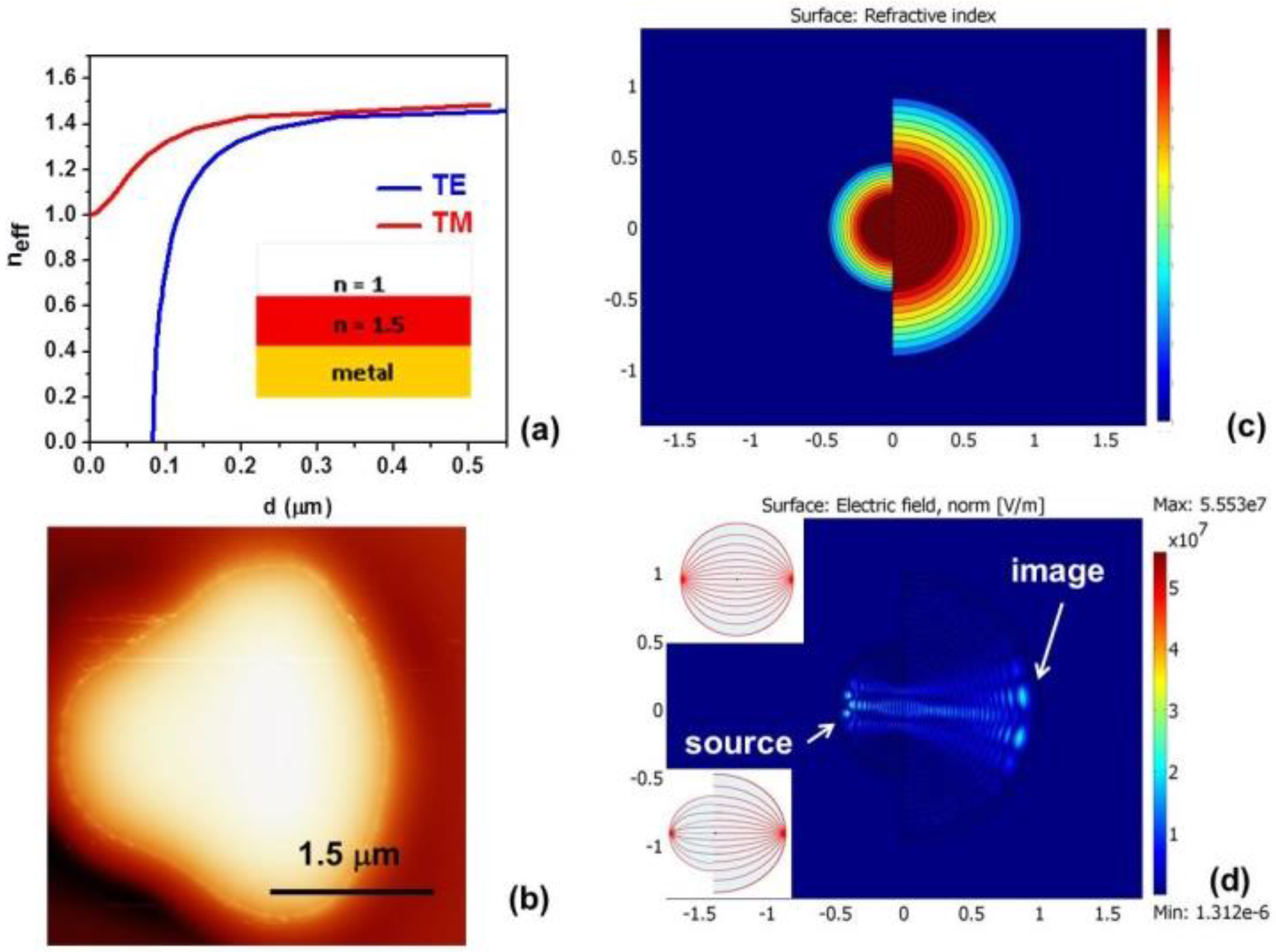
Unlike the earlier microdroplet design, which is difficult to fabricate and control, our current design is based on lithographically defined metal/dielectric waveguides. Adiabatic variations of the waveguide shape enable control of the effective refractive indices experienced by the transverse electric (TE) and transverse magnetic (TM) modes propagating inside the waveguides, as shown in
Figure 1a. They are defined as
neff =
kω
/c for each polarization, where the k vector at a given frequency ω is calculated via the boundary conditions at two interfaces as follows:
for the TM, and
for the TE polarized guided modes, where the vertical components of the wavevector
ki are defined as:
in metal, dielectric, and air, respectively. As illustrated in
Figure 1a, effective birefringence for the lowest guided TM and TE modes appears to be very strong at waveguide thickness
d < 0.4 μm, and both polarizations demonstrate strong index dependence on the waveguide thickness. This behavior may be used in building non-trivial birefringent TO devices if a waveguide thickness as a function of spatial coordinates
d(
r) may be controlled lithographically with enough precision.
We have developed a lithography technique which enables such
d(
r) shape control of the dielectric photoresist on gold film substrate, as illustrated in
Figure 1b. Shieply S1811 photoresist having refractive index
n ~ 1.5 was used for device fabrication. In traditional lithographic applications for the best results of pattern transfer the profile of resist should be rectangular or even with overhang. Our purpose is different. We want to create a more gradual edge profile. This can be done by disregarding typical precautions employed to make the edges sharp. Instead of contact printing (when mask is touching the substrate), we used soft contact mode (with the gap between the mask and the substrate). This allows for the gradient of exposure due to the diffraction at the edges, which leads to a gradual change of thickness of the developed photoresist. Different degrees of separation between the mask and the substrate produced progressively softer photoresist profile. Further variations of the profile were achieved by use of underexposure and underdevelopment, which produce much softer photoresist edges. This technique has been used previously to fabricate such TO-based devices as a modified Luneburg lens [
2]. However, no image magnification has been demonstrated in these experiments. On the other hand, as was noted in [
3], it is relatively straightforward to incorporate image magnification into such TO lens designs as Eaton and Maxwell fisheye lenses.
The refractive index distribution in a Maxwell fisheye lens is defined as
at
r <
R, where 2
n1 is the refractive index at the center of the lens, and
R is the scale factor. A reflective surface is assumed to be placed at
r =
R, so that
n < 1 values of the refractive index do not need to be used. In our experiments the role of such reflective surface is played by the lens edge. On the other hand, an inverted Eaton lens [
4] is defined as
n =
n1 for
r <
R, and
for
r >
R. Since the refractive index distribution in the fisheye lens is obtained via the stereographic projection of a sphere onto a plane [
5,
6], points near the lens edge correspond to points located near the equator of the sphere. Therefore, these points are imaged into points located near the opposite lens edge, as shown in the inset in
Figure 1d. The inverted Eaton lens has similar imaging properties.
As demonstrated in [
3], both refractive index distributions may be emulated with a suitable
d(
r) profile of a thin dielectric placed on top of a metal film, which is also evident from
Figure 1a. As shown in
Figure 1c,d, two halves of either Maxwell fisheye or inverted Eaton lens having different values of parameter
R may be brought together to achieve image magnification. The image magnification in this case is
M =
R1/
R2. Our numerical simulations in the case of
M = 2 are presented. Since the sides of the lens play no role in imaging, the overall shape of the imaging device can be altered to smooth the sharp corners, resulting in the magnifying fisheye lens shape shown in
Figure 1b, which was fabricated using the lithographic technique described above.
3. Results
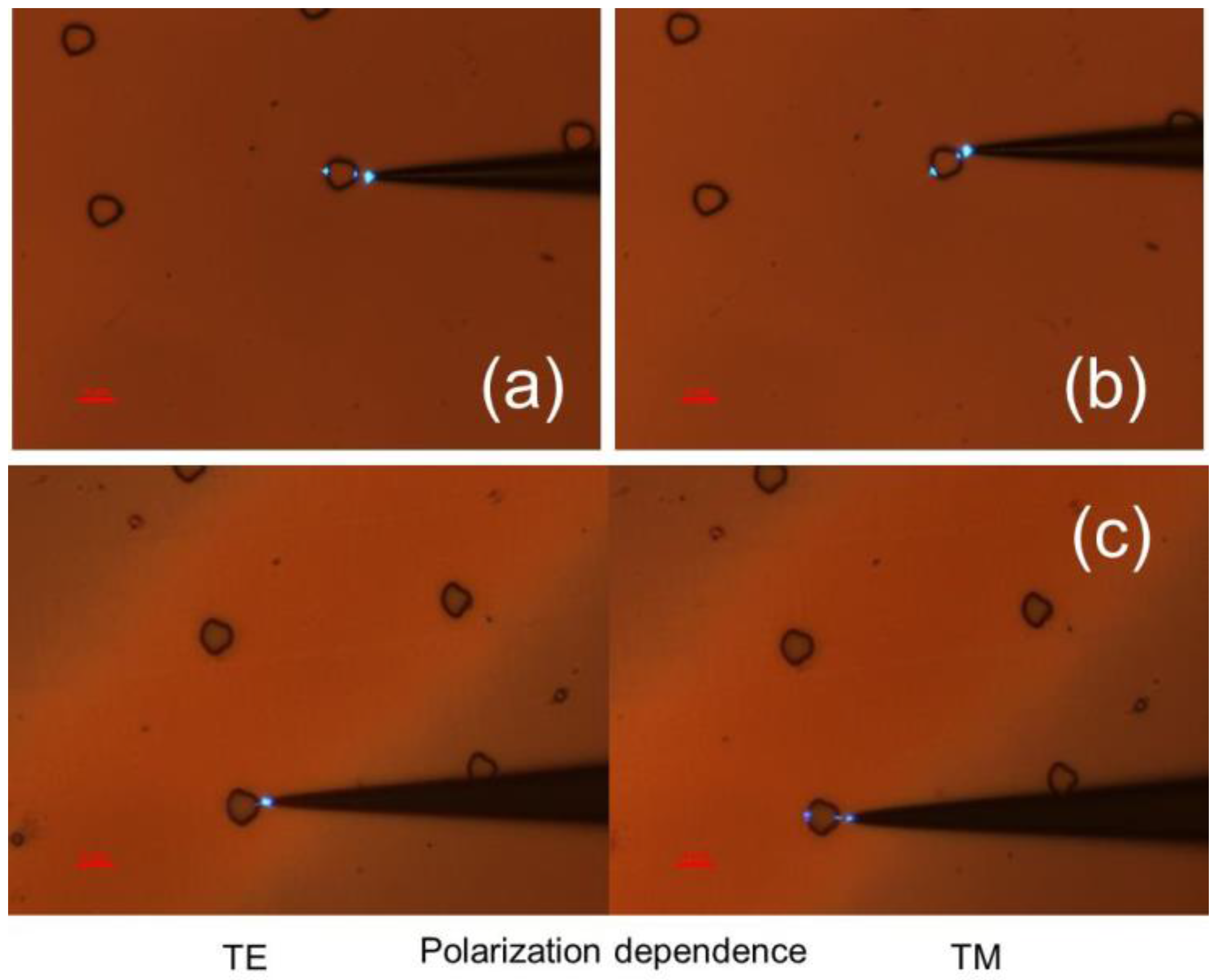
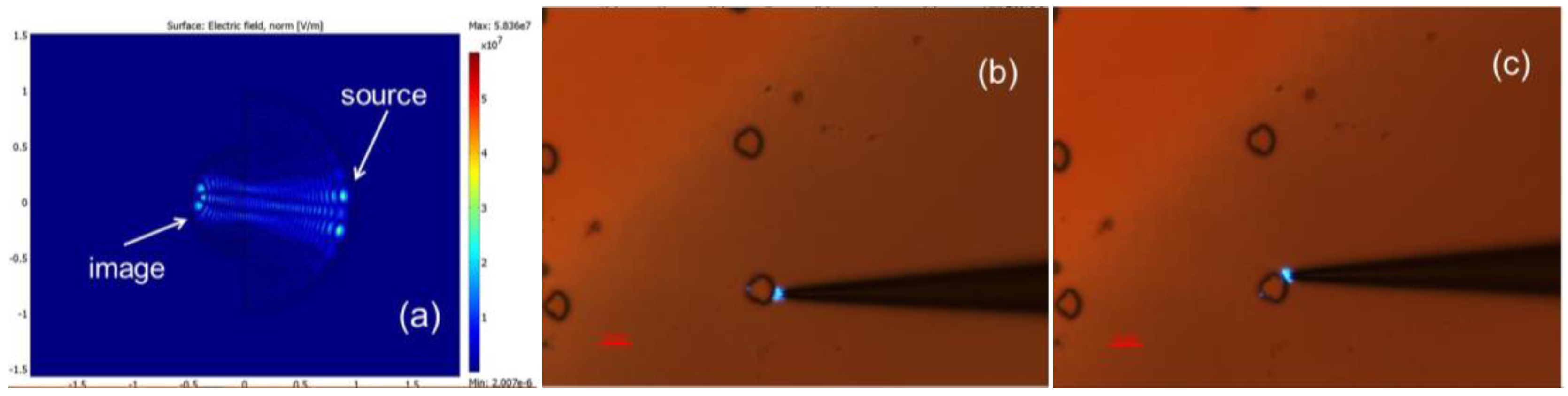
Experimental images in
Figure 2 demonstrate measured performance of the designed magnifying fisheye lenses. In these experiments a near-field scanning optical microscope (NSOM) fiber tip was brought in close proximity to the arrays of lithographically formed TO devices and used as an illumination source. As expected from the numerical simulations, an image of the NSOM tip was easy to observe at the opposite edge of the lens. Angular and polarization testing of individual lenses in the array agrees well with theoretical modelling presented in
Figure 1c,d. As illustrated by
Figure 1a, the same
d(
r) profile produces a different refractive index distribution for TM and TE polarized light.
Due to near zero effective refractive index near the device edge, a fisheye lens for TM light will operate as a spatial (directional) filter for TE light [
2]. We should note that while the NSOM fiber tip emits unpolarized light, polarization response of the image produced by a TO device can be clearly separated into the TM and TE contributions with respect to the plane of incidence of the source light. Polarization behavior of lenses in
Figure 2 demonstrates excellent agreement with theory.
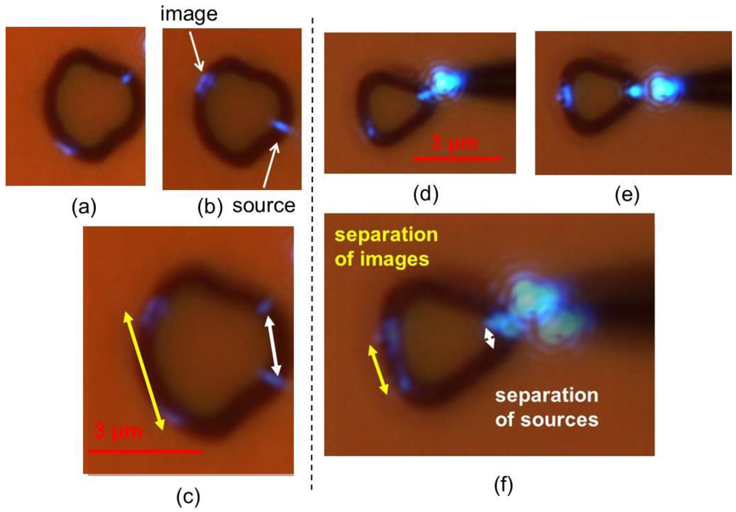
Image resolution and magnification of the fabricated magnifying Maxwell fisheye lenses may be evaluated based on images of lens testing presented in
Figure 3. Experimental testing of two fisheye lenses having different
M =
R1/
R2 ratio is shown in these images. The image resolution appears to be close to diffraction-limited (~ 0.6
λ at 488 nm), while image magnification is close to the design values
M = 2 and
M = 3, respectively. We should also note a very broad (almost 180°) angular range of the magnifying fisheye lens operation.
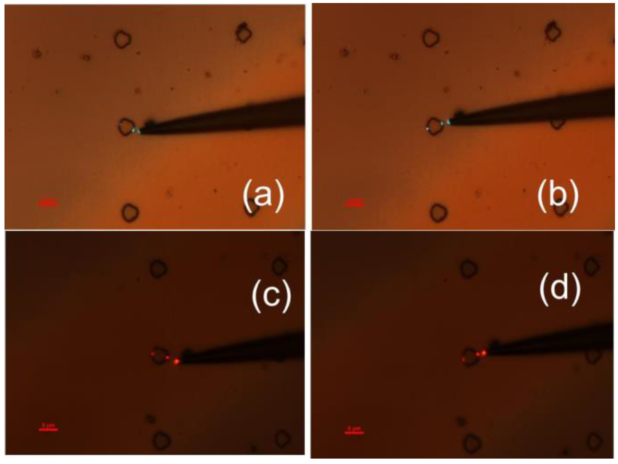
The projected broadband performance of the magnifying Maxwell fisheye lenses has been verified in the
λ = 488–633 nm range. Examples of such testing at 515 nm and 633 nm are presented in
Figure 4 (compare these images with
Figure 2a,b obtained at 488 nm). This experimental result may be understood similar to the broadband cloaking performance demonstrated in Reference [
1]. In all cases the effective refractive index of the tapered waveguide scales as
d/
λ at small
d. Thus, light at these wavelengths (488 nm, 515 nm and 633 nm) perceives the waveguide edge as having similar distribution of effective refractive index at all wavelengths. We have also verified (see
Figure 5) that the same lens used in reverse direction may be utilized to achieve image reduction. This fact is not trivial since the lens geometry is obtained by “gluing together” two halves of the Maxwell fisheye lenses having considerably different radii, which from the ray optics point of view may lead to ray scattering by the lens edges. Potentially, such an arrangement of the magnifying fisheye lens may find lithographic applications.
4. Discussion
Since the developed lithographic Maxwell fisheye lenses are based on tapered waveguide geometry, their high magnification and very compact design are highly suitable in waveguide mode sorting applications. Compact and efficient mode sorters are required in on-chip mode-division multiplexing [
7] and sensing [
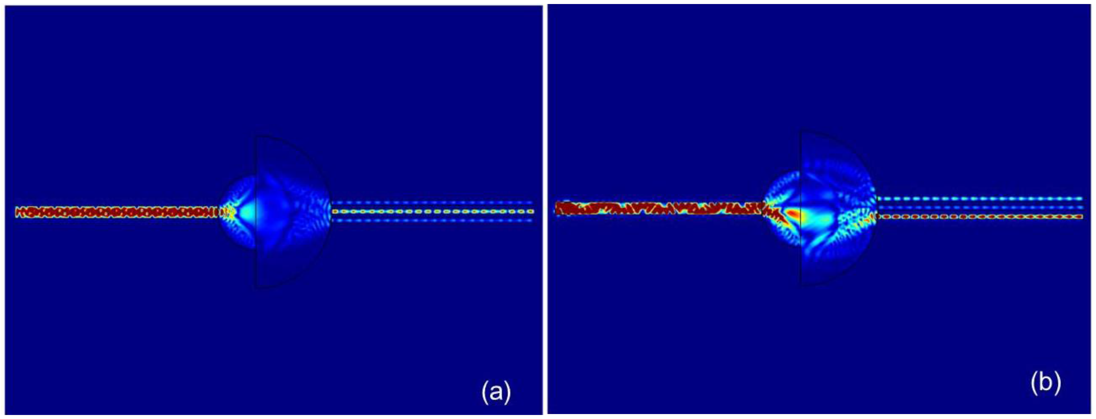
8] applications. COMSOL Multiphysics simulations of a Maxwell fisheye-based mode sorter are presented in
Figure 6, where the signal is sent in through a multimode waveguide from the left and out-coupled through three single mode output waveguides to the right. These simulations demonstrate excellent mode-sorting performance of a magnifying Maxwell fisheye lens, having spatial dimensions of only a few micrometers (the spatial dimensions are chosen to match experimentally fabricated lens shown in
Figure 1). As demonstrated by
Figure 6a, symmetric excitation of the multimode input waveguide leads to the output power being channeled primarily into the central single mode output waveguide. On the other hand, asymmetric excitation of the multimode waveguide leads to propagation of higher spatial modes, which are channeled preferentially into the side single mode waveguides, as shown in
Figure 6b.
Additional applications of the magnifying Maxwell fisheye lenses may include microscopy and spatially resolved fluorescence spectroscopy, as well as various nonlinear spectroscopy techniques, which require considerable local field enhancement.


