1. Introduction
One of the most interesting problems in nano-science in recent years has been to find a way to organize nanoparticles of different types into defined distributions. This could be close packed assemblies, dynamic clusters of different particles or well dispersed distributions of particles in a fluid phase. The goal is to produce a macroscopic composite material with properties that emerge from the particular controlled nanoparticle arrangement within. Such meta-materials are predicated to exhibit effects such as low or negative refractive indices, superparamagnetism, metal enhanced fluorescence and localized Plasmon resonance [
1,
2]. Nanoparticles can be difficult to disperse and control in an assembly due to the strong Van der Waals attractions between nano-scale particles. Uncontrolled assembly is a significant problem when surface interactions come to dominate at the nanoscale and surface chemistry strategies are usually employed to moderate these strong short-range surface forces. A common strategy is to use alkyl chain ligands such as octadecylamine (ODA). These chains provide a steric shield against irreversible aggregation by taking advantage of the high entropic cost to chain interdigitation.
Recently, advances have been made in the controlled assembly of very well ordered 2D nanoparticle lattices on solid substrates [
3]. These assemblies are assisted by ligand-ligand interactions between the particles. There are many unique applications for nanoparticle lattices, but the production of these materials on a large scale is a challenge. In addition, the particles need to be monodispersed. In a different approach, cluster assembled materials (3D disordered clusters of particles) can provide many of the advantages of ordered assemblies such as cooperative effects but with a more scalable approach and less strict dispersion requirements. Solution based assembly methods for particle clusters can be generalized to include many different particle combinations and recent attempts at assemblies of gold particle clusters [
4] have used a variety of particle spacing methods including biopolymers [
5,
6] proteins [
7,
8] and block copolymers [
9,
10,
11].
In this paper, we report a comparison study between two different Quantum dot (QD)/cholesteric liquid crystal (LC) composites. We will discuss our approaches to producing liquid crystal-based materials with defined nanoparticle distributions, focusing specifically on quantum dots owing to their unique size-tunable luminescent properties. Nanoparticle ligands can be designed to respond to the ordered molecular environment of a liquid crystal phase, inducing dispersion [
12], clustering [
13] or assembly at the interface of a liquid crystal phase transition [
14]. These techniques can provide easily scalable methods for producing a rich variety of quantum dot and nanoparticles assemblies. In particular, we present spectral characterization of quantum dots embedded in a cholesteric liquid crystal cavity with two different surface ligands.
Liquid crystals are ordered fluids characterized by molecular anisotropy. The most well known example of a liquid crystal phase is the nematic phase, typically formed from rod-like molecules in which the constituent molecules have local orientational order, defined by a director, c. The nematic phase is widely used in the display industry, for which molecular reorientation under an applied electric field provides the mechanism for optical switching. There are many possible liquid crystal phases, with varying degrees of positional and orientational order, but still maintaining fluid-like properties and these include the layered smectic phases, columnar phases with 2D hexagonal order and complex chiral phases such as the blue phases. The cholesteric phase, a chiral analog of the nematic phase is particularly interesting for photonic devices as it exhibits a 1D-photonic band gap in planar alignment that may be useful for lasing applications [
15] and spontaneous emission enhancement in single-photon sources for secure quantum communication [
16,
17]. Although much more complicated, the blue phases (a 3D lattice of twisted cylinders) also exhibit photonic band gaps and have been explored for similar lasing applications.
One of the strengths of using liquid crystal materials in a photonic device is their structural tunability. The photonic band gap of the cholesteric phase is tunable with temperature and applied electric field. In addition, the phase can be designed to have a specific band gap over a desired temperature range by varying its molecular composition. Since liquid crystals can be designed to exhibit phases of interest at and around room temperature, material mixing and processing is relatively easy. Liquid crystals can be used to create electro-optically active thin films and apply them to a variety of different device geometries without the constraints of solid material growth or lithography. This ordered fluid medium provides an ideal environment to create a dispersion of QDs for printable photonic devices. Once assembled, the materials containing nanoparticle structures or dispersions can be applied to a substrate and polymerized if desired to produce a permanent film or coating. Applications for QDs dispersed in fluid media include solar concentrators and printable laser inks.
2. Experimental Section
In this section, we first describe our methods for preparing composite cholesteric/QD materials, then, in the following results section, we demonstrate how resonant fluid photonic cavities can result from the co-assembly of luminescent nanoparticles in the presence of cholesteric liquid crystalline ordering.
Figure 1.
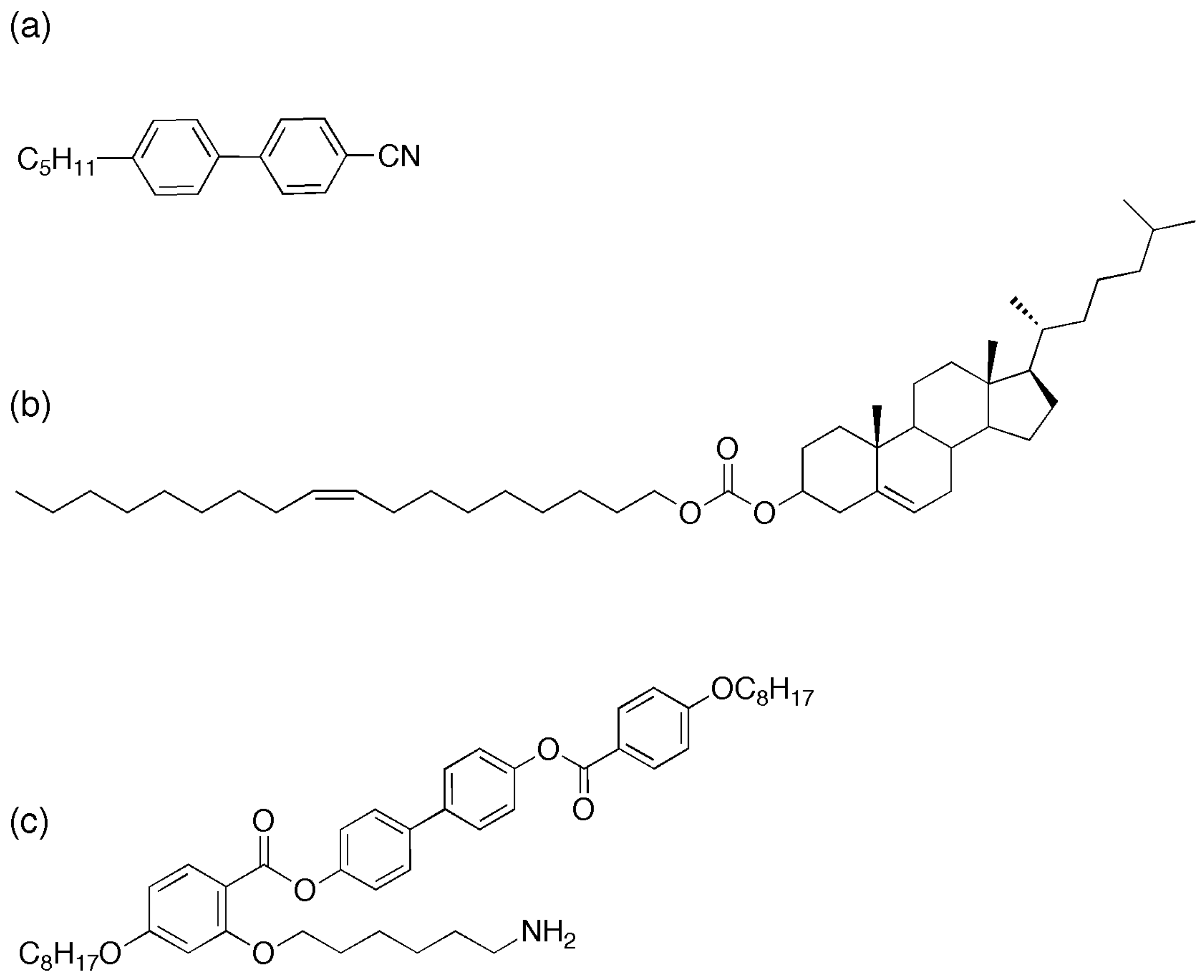
Liquid crystal compounds used in this study (
a) 4-Cyano-4’-pentylbiphenyl (5CB), (
b) Cholesterol oleyl carbonate (COC) and (
c) the mesogenic ligand (L1) [
18].
Figure 1.
Liquid crystal compounds used in this study (
a) 4-Cyano-4’-pentylbiphenyl (5CB), (
b) Cholesterol oleyl carbonate (COC) and (
c) the mesogenic ligand (L1) [
18].
We start with commercially available quantum dots with octadecylamine (ODA) surface ligands (5.2–6.2 nm, NN Labs Inc) (ODA-QDs) onto which mesogenic ligands can be exchanged. Synthesis of the mesogenic ligand used in this paper was carried out as previously reported [
18],
Figure 1c shows the molecular structure of the ligand. These ligands exhibit liquid crystalline phases in their pure state with high clearing points above 100 °C—a contrast with the host phase (5CB (4-cyano-4ꞌ-pentylbiphenyl)), which exhibits the nematic to isotropic transition at 34 °C (
Figure 1a). As previously described [
18], ligands are exchanged on to the surface of the CdSe/ZnS quantum dots to form LC–QDs. These new particles are then dispersed into the cholesteric liquid crystal by wt%. Bath sonication for eight hours at 40 °C in the isotropic phase ensures an excellent initial dispersion, verified by fluorescence microscopy.
Cholesteric liquid crystal is prepared by mixing cholesterol oleyl carbonate (COC, Sigma Aldrich,
Figure 1b and the nematic liquid crystal, 4’-pentylꞌ4-biphenylcarbonitrile (5CB, Sigma Aldrich) in varying proportions by weight. The mixtures were sonicated at 43 °C (above the isotropic transition temperature for both compounds) for 1 h to ensure good mixing. CdSe/ZnS QDs with octadecylamine ligands and an emission in toluene solution centered at 609 nm, were added to the LC mixtures at a concentration of 0.01–0.02 wt%, then sonicated again for 1–6 h to obtain the final QD–LC composite.
Fluorescence microscopy is used to image the spatial distribution of quantum dots in the host phase. In all experiments presented here we used CdSe/ZnS core shell quantum dots with a 620 nm emission peak. Fluorescence microscopy was carried out on a Leica DM2500P microscope in reflection mode using a 20× or 40× objective. For the 620 nm QDs a 510–560 band pass filter was used with a white light mercury lamp illumination. Emission was detected using a 580 nm dichroic mirror and a 590 nm long pass filter. The microscope can also be used in transmission mode with the sample between crossed polarizers to image liquid crystal birefringence. Samples were mounted on standard glass microscope slides under a cover slip.
To prepare a planar alignment coating, glass slides were spin coated with a 1 wt% aqueous polyvinyl alcohol (PVA) solution (Sigma Aldrich), dried in air and rubbed to establish the required orientation. To prepare a homeotropic alignment layer, glass slides were dip coated for 5 min in 0.5 mM aqueous hexadecyltrimethylammonium bromide (CTAB, Sigma Aldrich) solution.
For QD PL measurements, a VERDI 532 nm continuous wave excitation laser is focused on the sample through a 100× Nikon objective to produce a diffraction-limited spot diameter of approximately 600 nm. Samples are mounted on a motorized high-resolution scanning stage, and spectra recorded with an Acton 300i Spectrometer that disperses the signal onto a thermo-electrically cooled CCD camera with a 0.18 nm resolution.
Samples were mounted on glass slides for characterization prepared with a planar alignment layer and initially heated to 50 °C into the isotropic phase. The slides were then cooled at a rate of 1 °C/min from the isotropic phase into the nematic phase and left to anneal at 30 °C overnight.
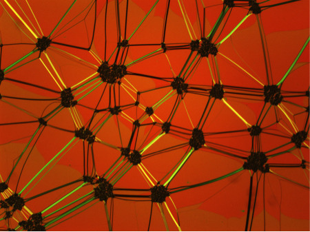
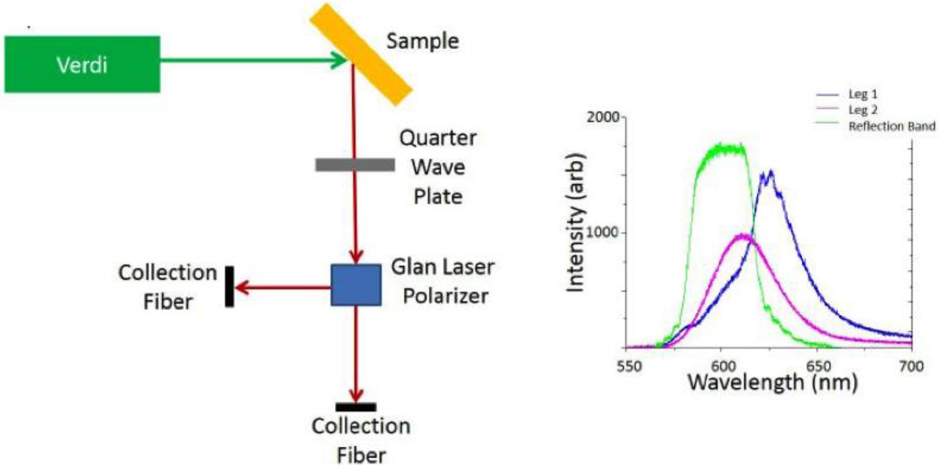
When the sample is excited with 532 nm laser light we analyze device emission via two collection fibers as shown in
Figure 2 in order to probe the two circularly polarized components of the QD emission from the sample simultaneously. The circularly polarized light is first converted to a linearly polarized beam using a quarter wave plate, and then passed through a Glan laser polarizer that allows us to measure the intensities of both the s and the p polarizations. It is clear from the spectral data shown in the Figure that one component contains emission (pink) that is not affected by the reflection band (green),
i.e., the incident polarization was of opposite handedness to that of the cholesteric phase, and one that matches the cholesteric twist, resulting in emission enhancement effects. In the blue curve, we observe a small amount of coupling and amplification from the edge of the cavity, demonstrating cavity coupling with the embedded QDs.
Figure 2.
Schematic of setup used to collect polarization resolved QD emission, and a typical emission example of an emission spectrum from embedded QDs in the cholesteric phase showing both linear components of the emission overlaid on the reflection spectrum for the stop band of the cholesteric.
Figure 2.
Schematic of setup used to collect polarization resolved QD emission, and a typical emission example of an emission spectrum from embedded QDs in the cholesteric phase showing both linear components of the emission overlaid on the reflection spectrum for the stop band of the cholesteric.
Controlling the dispersion of quantum dots, or other similarly sized nanoparticles in liquid crystal, thus forming a stable suspension without aggregation is an important goal for photonic applications. A stable distribution of particles may be desired but the materials can age—particles falling out of suspension and degrading device performance. Isotropic ligands such as ODA inherently produce defects in an oriented liquid crystal environment. A particle with uniform planar or homeotropic anchoring will induce a topological defect in the liquid crystal director field due to the frustration between local molecular alignment and anchoring conditions at the particle surface. We observe splay bend deformation of the local liquid crystal director as a result of nanoparticle inclusion in the nematic phase [
13]. The free energy cost of these deformations is described by the Frank elastic constants. QDs and other nanoparticles tend to cluster together in the nematic phase to reduce this energy cost and control over this clustering effect is important to produce uniform stable materials. However, the formation of small nanoparticle clusters may offer some advantages for specific photonics applications.
3. Results and Discussion
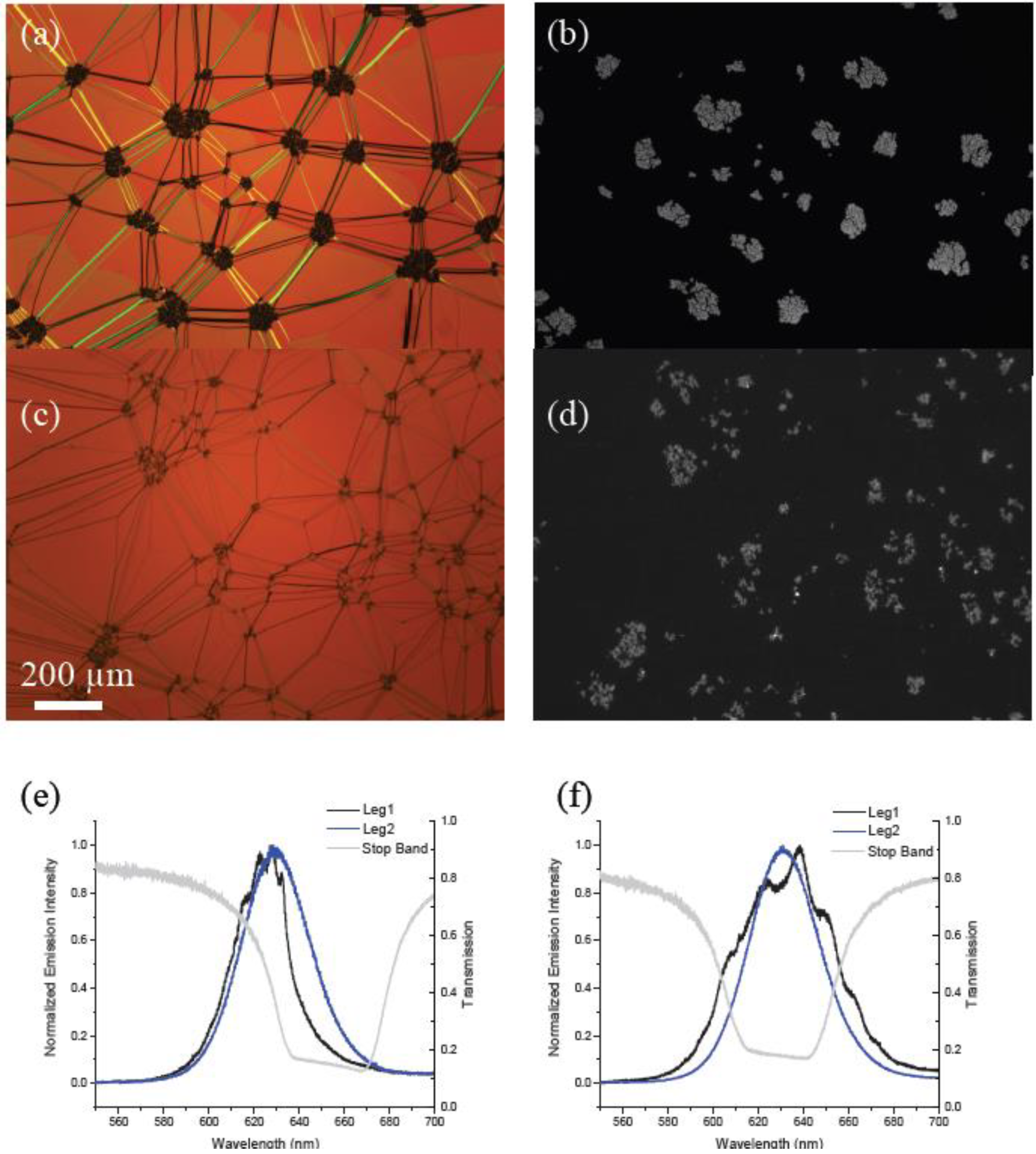
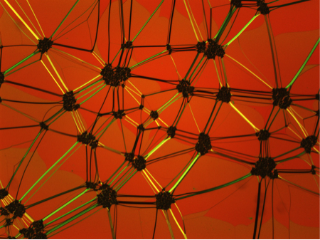
Figure 3a,c shows polarized optical microscopy images of the cholesteric texture for both the ODA–QD and LC–QDs embedded in the cholesteric phase along with fluorescence microscopy images of the same area showing QD distribution. One of the most apparent differences here seen in the optical microscopy is that at this concentration (0.1 wt%), the ODA–QD mixture exhibits much larger aggregates in the cholesteric liquid crystal (CLC) whereas the LC–QDs produce small but also distinct aggregates. This result is consistent with prior results [
13,
14] in which the nematic phase transition acts to assemble the included nanoparticles into templated structures at the phase transition. At 0.1 wt% and above, we expect aggregate formation for both of these particle types [
18].
Figure 3.
Polarized optical microscope images of 0.1 wt% mixtures of (a) ODA–QDs and (c) functionalized LC–QDs dispersed into a planar aligned cholesteric film shown next to corresponding fluorescence microscopy images (b) and (d). (e) and (f) show corresponding emission spectra for two different circular polarizations for the QDs embedded in these fluid cavities. Superimposed are transmission curves for circularly polarized light demonstrating the position of the stop band in each material.
For particles with the LC ligand, large assemblies were recently reported to form when dispersed in the isotropic phase and cooled through the nematic phase transition. The mesogenic ligands may act to stabilize these structures (
Figure 4) providing a mechanism to create hierarchical composite materials. Recently, our group developed a new methodology to assemble large-scale QD structures using the particles’ spatial distribution across the nematic to isotopic phase transition [
13,
14].
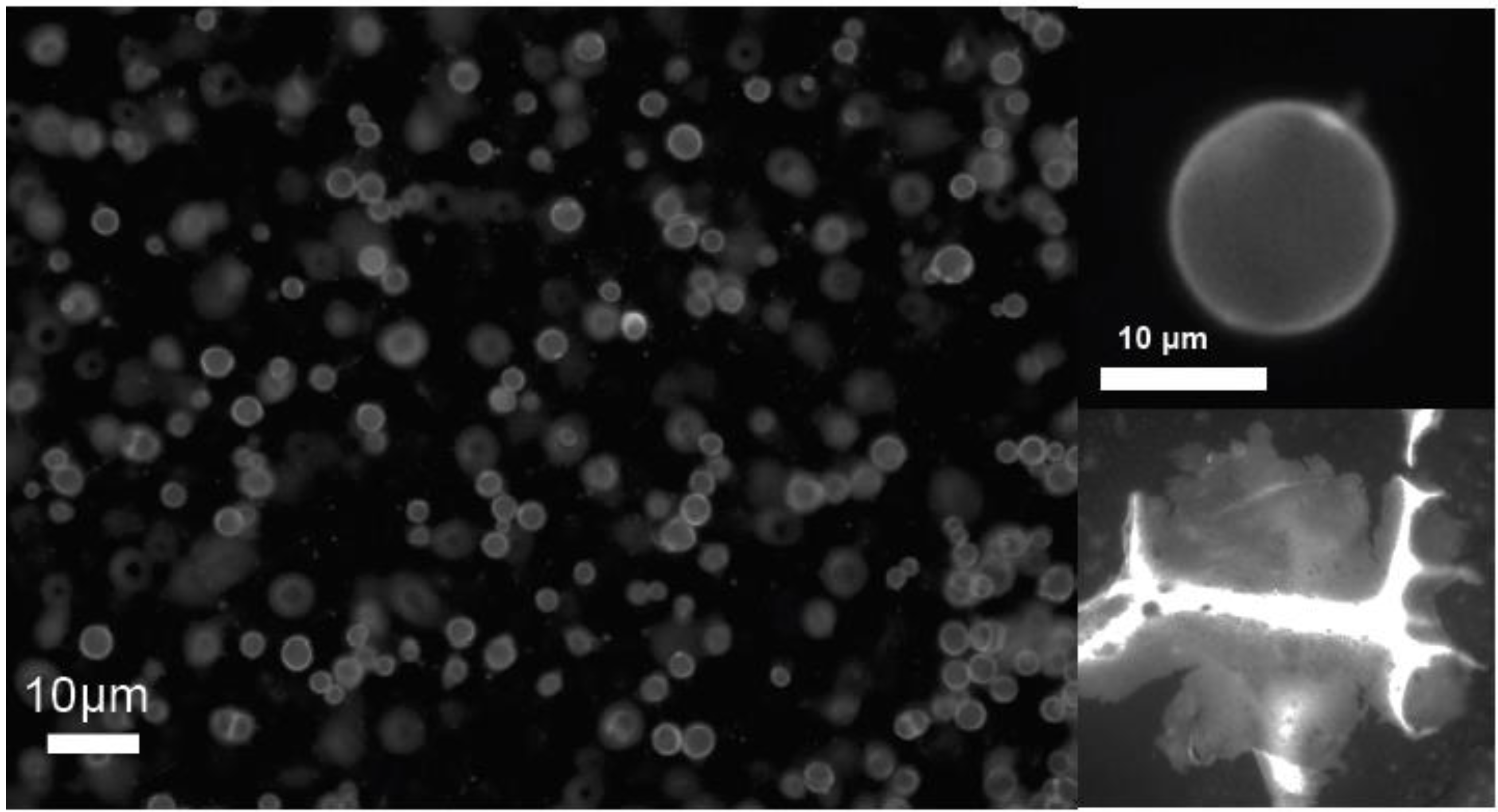
Figure 4a,b shows a fluorescence image of QD “vesicles” or micro-shells stabilized by this process in which the particles are densely packed with an average separation of ~11 nm [
14]. Quantum dot membranes an also be prepared by a similar process (
Figure 4c) in which the nanoparticles are stabilized in an interfacially templated assembly.
Figure 4.
Fluorescence microscope images of quantum dot micro-shells, or “vesicles” and a flat membrane generated by phase transition templating (ref). (a) multiple shells suspended in the nematic phase, (b) a single QD shell and (c) a crumpled membrane structure formed by the same method.
Figure 4.
Fluorescence microscope images of quantum dot micro-shells, or “vesicles” and a flat membrane generated by phase transition templating (ref). (a) multiple shells suspended in the nematic phase, (b) a single QD shell and (c) a crumpled membrane structure formed by the same method.
When the devices shown in
Figure 3 were excited with the 532 nm continuous wave laser, we observed characteristic emission for QDs coupling with the cholesteric cavity for both types of particle (
Figure 3e,f). The results are consistent with recent reported data from our group for ODA–QDs only [
19,
20]. In the ODA–QD device we observed that good cavity coupling as shown in
Figure 3e as an example was very location dependent. This should be expected for a material in which almost all of the emitting particles are located within dense aggregates using an excitation spot size of 600 nm. In comparison, the LC–QD device showed a much more uniform spatial performance. This result supports the idea that although aggregates can be seen optically, there are also many QDs dispersed throughout the phase.
In a second experiment, we investigated the effect of localizing the QDs outside of the cholesteric fluid when compared with embedding the particles. These comparison samples were prepared from films of ODA-QDs suspended in PMMA and toluene at 0.8 wt% QD in PMMA. The QD/PMMA solution was deposited on glass using a spin coater and cured at 140 °C for one hour. After curing, an alignment layer of PVA was deposited on top of the film as is done for clean glass. The film was then covered with 57.5%, 42.5% COC/5CB mixture to create a photonic cavity that overlaps with the QD emission.
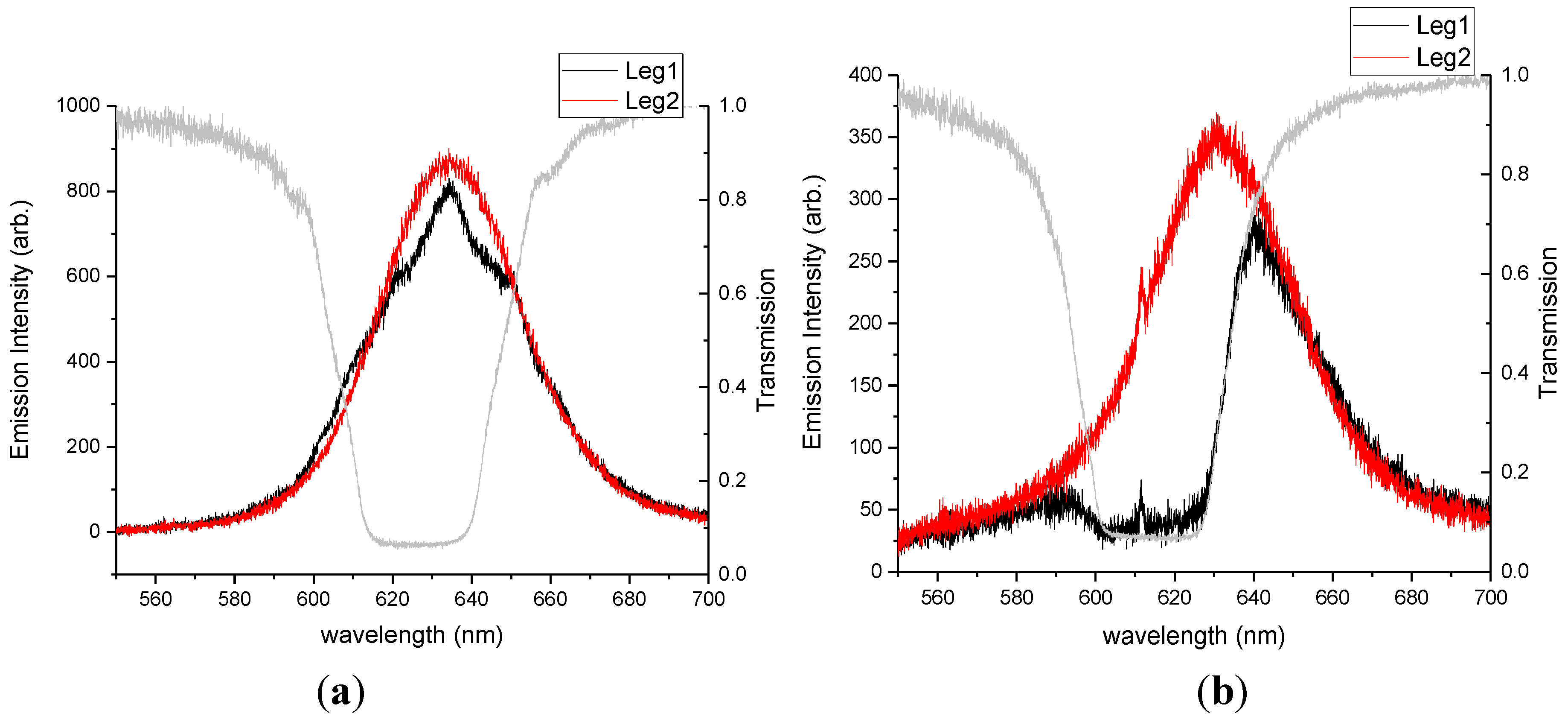
We expected that the cavity coupling would be stronger for similar number densities of QDs emitting from within the cholesteric cavity when compared with emitters located outside the cavity. To test our hypothesis, we prepared two different 0.02 wt% mixtures of QDs in CLC, ODA–QDs and LC–QDs, functionalized with the mesogenic ligand shown in
Figure 1c. Such a low concentration of QDs was used in this case to ensure a uniform dispersion of nanoparticles in the phase (CLC). The emission data presented in
Figure 5 clearly demonstrate the results. QD films placed outside the cavity produced minimal detected emission in leg 1 as only one handedness of light was able to pass through the cavity. A comparable concentration of QDs dispersed in the cavity produced emission and clear fringes characteristic of cavity coupling.
Figure 5.
Photoluminescence spectra for 0.02 wt% ODA-QDs. This data compares (a) QD dispersion in the cholesteric phase with (b) QDs located beneath the cholesteric film.
Figure 5.
Photoluminescence spectra for 0.02 wt% ODA-QDs. This data compares (a) QD dispersion in the cholesteric phase with (b) QDs located beneath the cholesteric film.
4. Conclusions
In this paper, we investigated quantum dots dispersed in a cholesteric photonic cavity for potential liquid crystal laser applications. We primarily compared the effects of changing the QD ligand to a mesogenic molecule recently studied by our group. In addition, we also looked at locating the QDs outside of the cavity compared with the composite materials.
We found that QDs used in the study produced cavity coupling signatures, but, at fairly low loading concentrations, they also suffered from significant aggregation. The LC–QDs demonstrated reduced aggregation, although we should note that it is still not clear what the role of this aggregation is on device performance. It may be that as long as the bulk cholesteric texture is not too disrupted full dispersion is not necessary for a useful device. Interestingly, we noted that strong coupling effects, as measured with a 600 nm spot size, where spatially dependent indicating that hitting the material close to an aggregate produced stronger effects due to a larger localized emitter concentration.
No significant effects on the emission spectrum were observed between the two particle types, despite the fact that QDs in the ODA–QD clusters are closer together (~7.6 nm [
13]) compared with LC–QDs (~11 nm [
18]). Localizing the QD film outside the cavity produced detrimental effects on performance, as the QD emission detected in leg 1 was reflected and did not travel through the CLC.
From these results, we speculate that very well dispersed QDs are not necessary to produce strong cavity coupling in a cholesteric liquid crystal device for lasing applications and that aggregation may be advantageous for increasing signal strength. Such results support recent observations of lasing in a similar device with very high QD content (up to 8 wt%) [
21] in which aggregation and non-uniform QD distribution is likely. We propose that controllably assembled QD aggregates such as the QD shells [
14] and membranes shown in
Figure 3 may find application in photonic devices, provided the host phase alignment is not significantly disrupted by the embedded emitting structures.

