Article

Broken Bar Diagnosis for Squirrel Cage Induction Motors Using Frequency Analysis Based on MCSA and Continuous Wavelet Transform

by
Danilo Granda ,
1,
Wilbert G. Aguilar
2,3,4,*,
Diego Arcos-Aviles
1,5 and
Danny Sotomayor
1,6
1
Departamento de Eléctrica y Electrónica, Universidad de las Fuerzas Armadas ESPE, 171-5-231B Sangolquí, Ecuador
2
Departamento de Seguridad y Defensa, Universidad de las Fuerzas Armadas ESPE, 171-5-231B Sangolquí, Ecuador
3
Centro de Investigación Científica y Tecnológica del Ejército CICTE, Universidad de las Fuerzas Armadas ESPE, 171-5-231B Sangolquí, Ecuador
4
Knowledge Engineering Research Group GREC, Universitat Politècnica de Catalunya UPC-Barcelona TECH, Barcelona 08040, Spain
5
Propagation, Electronic Control and Networking Research Group—PROCONET, Universidad de las Fuerzas Armadas ESPE, 171-5-231B Sangolquí, Ecuador
6
Wireless Networks Research Group—WICOM Energy, Universidad de las Fuerzas Armadas ESPE, 171-5-231B Sangolquí, Ecuador
*
Author to whom correspondence should be addressed.
Math. Comput. Appl. 2017, 22(2), 30; https://doi.org/10.3390/mca22020030
Submission received: 10 January 2017 / Revised: 5 April 2017 / Accepted: 7 April 2017 / Published: 11 April 2017

Abstract

:
The importance of early fault detection in electric motors has attracted the attention of research groups, as the detection of incipient faults can prevent damage spreading and increase the lifetime of the motor. At present, studies have focused their attention on optimization procedures used for fault detection in induction machines to achieve a quick and easy-to-interpret assessment at an industrial level. This paper proposes an alternative approach based on the Continuous Wavelet Transform (CWT) for broken bar diagnosis in squirrel cage induction motors. This work uses the Motor Current Signature Analysis (MCSA) method to acquire the current signal of the induction motor. The novelty of this study lies in broken bar detection in electric machines operating at non-load by analyzing variations in the spectrum of the motor’s current signal. This way, the faults are presented as oscillations in the current signal spectrum. Additionally, a quantification of broken bars for the same type of motors operating at full-load is performed in this study. An experimental validation and the comparison with the Fast Fourier Transform (FFT) technique are provided to validate the proposed technique.

1. Introduction

Three-phase motors are widely used in the industry due to their ease of manufacture and low maintenance [1]. In most industrial applications, the AC motors are subject to frequent start-stop cycles resulting in wear and cracking of the electric machine elements [2], which could produce rotor, stator, and bearing damage of the induction machine [2,3,4].
The motor operation in non-ventilated environments causes the motor efficiency reduction and increases the failure risk due to broken bars in the induction machine rotor, since the temperature increase in the rotor could provoke the bars breaking [5,6] (e.g., thermal stresses due to thermal overload and unbalance, hotspots, or excessive losses) [7]. In industrial applications, where motor overload is needed for long time intervals, the motor overload produces thermal stress in the motor’s internal components, since the machine is forced to work in different operating conditions from those envisaged by its original design [8].
The presence of a fault in an electric motor associated with a critical industrial process leads to emergency interruptions [9], which causes production process losses [8,10,11]. Therefore, early fault detection is required to identify incipient fault presence in induction motors, and consequently to avoid these problems [6,12]. For motor fault diagnosis: thermal imaging, electrical, acoustic, and vibration signals are analyzed in [1,13]. These studies are developed to determine the characteristics of the signals analyzed as well as to identify the problems related to faults in electric motors.
The diagnosis and fault detection methods used in induction motors are based on the effective analysis, in the frequency domain, of the induction machine electrical parameters [2,14,15]. This analysis is usually performed by Fast Fourier Transform (FFT) [10,14] and Hilbert Transform [2,16]. The FFT performs the fault characterization by representing the current signals as the sum of sine and cosine functions, which transforms a time domain signal into frequency domain signal [14,17,18].
The FFT and Hilbert transforms differs in the fault characterization process. FFT uses the sum of sine and cosine functions spectrums of the current signal and Hilbert transform uses the current signal convolution with the function 1/t and shifts the phase components 90° (i.e., sines are transformed to cosines and vice versa) [2]. The Hilbert transform retains the positive content of the original signal frequency while eliminating negative frequencies and increasing by two the DC component. However, current and voltage characterization using both techniques is difficult; the frequency resolution forces the addition of dedicated processes where automatic learning algorithms are executed to identify slight differences between signals [19,20], which increases the software and hardware complexity. The Hilbert transform is used as a complementary tool to the Fourier transform (e.g., to study frequencies that occur instantaneously).
The FFT has disadvantages in early fault detections due to the small amplitude of the failure components [4]. Consequently, the fault components are hidden by noise introduced in the data acquisition process. The use of the Continuous Wavelet Transform (CWT) is proposed in [21] to address this problem. The CWT allows evaluating signals by signal decomposition into details for different scales. In addition, CWT performs the decomposition of the current signal into detail coefficients [22], quantifies the energy level for each detail coefficient, and determines the instant when a failure occurs according to the energy level [22,23]. Conversely to FFT transform, the wavelet transform can extract the signal characteristics in time and frequency domains [24]. Based on the wavelet properties, different types of mother wavelets can be used to perform the analysis [25,26,27]. The wavelet transform is considered a useful tool for applications where signal feature extraction is required (e.g., pattern recognition, machine learning, and classifiers) [19,20,28,29,30,31].
Selection of the mother wavelet is quite arbitrary. Therefore, the adequate selection of mother wavelet minimizes errors in motor fault diagnosis [32]. In this regard, Daubechies, Coiflet, and Meyer Wavelets use orthogonal wavelet analysis, which is limited for a discrete set of scales (e.g., scales in powers of two) and can be implemented using simple digital filtering techniques [33]. Conversely, non-orthogonal wavelet analysis by means of Morlet-CWT, where an arbitrary scale set can be used to build complete spectral graphs. In this regard, the analysis of current signals through CWT generates detailed information in the time-frequency spectrum [27]. The Morlet-CWT signal processing technique applied for detection of broken bars in electric machines is used to represent time-domain motor current signals in the time-frequency spectrum. Therefore, time-frequency spectrum representations with different details can be observed by choosing an initial scale to obtain the characteristics of motor current signal. This scale can be increased to achieve more detailed information in the time-frequency spectrum.
The aforementioned techniques use the Motor Current Signal Analysis (MCSA) as a common method to acquire the current signals from the induction machine [2,27,34]. The MCSA is a widely used method for monitoring failures in induction motors [10,23,34] (e.g., rotor and winding faults [18,35,36]). In order to prevent the premature failure of induction motors [37], the MCSA method and signal processing techniques are applied for early broken bar detection in three-phase induction motors. The lack of this early fault detection may cause damage spread and motor destruction [37,38]. The existence of broken bars in an electric machine, which is the main reason for rotor asymmetry and motor magnetic field changes [6], is evidenced by the appearance of two frequency components located close to the motor operating frequency [15,20,39].
This paper presents the analysis of motors with broken bars using the MCSA method and the CWT processing technique (i.e., time-frequency spectrum) to identify features associated with this fault. The Morlet mother wavelet is used in this study due to its time-frequency localization characteristics. The combination of a non-invasive method for data acquisition and a signal processing technique, allows performing the broken bars detection in induction motors with non-load. The current signal analysis of non-load motors with broken bars shows signal spectrum fluctuations with respect to healthy machines. These fluctuations increase accordingly to the broken bars number and can be clearly appreciated as fault indicators when the motor operates at full-load. The proposed procedure reduces both the processing time and the tasks required to examine a signal regarding the conventional techniques.
In contrast with other studies presented in the literature, the contribution of this work lies in the fault diagnosis of broken bars using only the motor current signal magnitude for a motor operating at non-load. In order to guarantee the fault diagnosis procedure, the evaluation of a faulty motor with different number of broken bars is performed. In order to verify the effectiveness of the proposed procedure, the behavior of faulty motor operating at full-load is analyzed. In both cases (i.e., motor operating at non-load and full-load) the fault identification is evidenced through the presence of fluctuations and oscillations in the motor current signal spectrum. An advantage of the proposed method is that the current signal analysis can be performed using the current signal of the entire process at the same time, i.e., considering the signals of motor starting, stop, and transients of a motor operating at non-load and full-load, which differs from other methods where the analyses for a motor operating at full-load and non-load have to be accomplished separately.
The rest of the paper is organized as follows. Section 2 gives a brief overview of the relevant literature. The proposed procedure is presented in Section 3. Section 4 shows the experimental results and comparison between the proposed procedure and the FFT technique. Finally, Section 5 presents the main conclusions and future works of this paper.

2. Related Works

Current signal analysis is used in several fault diagnosis methods, since the data acquisition is achieved through a non-invasive method (e.g., current meters). This process can be performed with simple software [40], becoming an excellent alternative for industrial environments.
As mentioned before, the FFT and the Hilbert transform are signal processing techniques commonly used for fault detection in electric machines. Both techniques use spectral analysis of motor current signals [10,34], which quantifies the failure level in the induction machine according to the order of harmonic components and the magnitude of the spectrum.
Fault detection using numerical simulations was performed in [37,41], where the current signals were measured through MCSA method. In these studies, the current signals obtained by means of the electric machine mathematical model were compared with the measured signals to demonstrate noise addition in the signal data acquisition process and the increase of speed and torque oscillations with the rotor bar breakage. In [4,40] Signal to Noise Ratio (SNR) during the sampling period was evaluated. The results of these studies provide evidence for the problems in accuracy of spectral analysis, since the distortion induced by the noise during data acquisition leads to signal spectrum changes. To improve fault diagnosis procedure, the analysis of asymmetric components of unbalanced electric system was studied in [42,43]. The signal harmonics of Zero-Sequence Current (ZSC) analysis were proposed in [42] to detect higher-order harmonic components (e.g., 3rd- and 5th harmonics). However, this method does not show reliable results when motors with non-load are analyzed, since the fault components are hidden in the motor operating frequency. To have efficient fault detection, an automatic harmonic component analysis was presented in [43], where the analysis was performed by periodic monitoring of the magnitude changes that identify the current motor state. The main advantage of this technique is to simplify the analysis through graphical interpretation of harmonic components in the frequency spectrum, which is done using a bar chart, allowing quick and easy failure detection.
The FFT and Hilbert transform applied to fault diagnosis of medium- and high-power motors depends on the rotor slip [4]. The tests should be accomplished on motors with certain load levels to achieve reliable results; for instance, a motor operating at 35% of the rated load is recommended in [2]. In addition, the SNR should be high in the data acquisition process to avoid frequency distortion in the spectrum, allowing accurate harmonic component evaluation. However, the motor study when it is operating at low frequencies needs a high-resolution spectral analysis, which leads to signal acquisition over long time periods, increasing the fault diagnosis time [2,4,27] and requiring an improvement in the software and hardware used for signal acquisition.
The wavelet transform is used to provide a signal processing technique to overcome the drawbacks presented by prior techniques. The wavelet transform is used in [44] to examine and detect possible failures in short duration signals (e.g., transient state), this process represents the motor starting in time-frequency domain, where for faulty motors the increment of low-frequency components is identified. The main disadvantage of this analysis lies on the difficult interpretation of time-frequency graphs, since slight variations are presented in the spectrum. In addition, the current signal analysis of motors with and without failures by means of the Wavelet Packet Transform (WPT) is presented in [45]. The WPT technique decomposes the signal at different levels known as approximation and detail coefficients. The results presented in [45] reduced the computational cost and confirm the amplitude increase at 0–60 Hz frequency levels. Moreover, the Discrete Wavelet Transform (DWT) and the WPT were used together in [19,46] to quantify the amount of energy in low frequencies detail coefficients, which identified the frequency ranges of harmonic components induced in the stator [47,48]. Furthermore, different mother wavelets were applied in the fault diagnosis procedure. A comparison of Daubechies 40–45 and Symlet20 mother wavelets was presented in [33], where the results showed that the approximation and detail coefficients of the analyzed signal had similar decomposition content for both mother wavelets. Additionally, the wavelet transform can be applied for transient analysis of an induction motor as presented in [49]. An analytic wavelet transform via frequency B-Splines was used to analyze the fault effects associated with broken bars. However, a steady-state analysis is not considered in this study. Note that the suitable selection of the mother wavelet leads to efficient results.

3. Proposed Approach

The proposed approach is based on a continuous Morlet wavelet transform applied to the current signals of a three-phase induction motor. The proposed procedure involves the correlation between the motor current signal and the mother wavelet, and the graphing of the time-frequency spectrum of current signals, where the comparison is interactively performed at different scales of mother wavelet (i.e., the convolution between the analyzed signal and the mother wavelet characterized at different scales).
The large scales allow us to know the signal characteristic at low frequencies, whereas the small scales allow us to know the signal characteristics at high frequencies. Following this procedure, two variable functions f(s,τ) are obtained, representing the analyzed signal scale and translation, respectively. Similarly to [25,26], the wavelet coefficients are transformed into the translation-scale coefficients to be represented in the time-frequency spectrum, which are displayed to perform a comparison between the motor currents of a healthy motor and a faulty motor with different fault levels (i.e., one, two, and three broken bars).
The general definition of a mother wavelet is used for the current signal processing. The mother wavelet is defined as follows [26,27]:
ψ s , τ ( t ) = 1 | s | ψ ( t τ s )
where Ψs is the mother wavelet, and s and τ are the mother wavelet scale and translation, respectively. Note that a signal must meet certain conditions before it can be considered to be mother wavelet. The signal has to be properly located in time (i.e., admissibility), its average energy should be null, and it should behave as a band-pass filter with fast decay on ωs = 0 and when ωs → ∞ [25,26], ωs being the angular frequency.
The wavelet transform analyzes non-stationary signals, specific phenomena, discontinuities, and sudden changes in the derivative of a signal. It has an invariance property relative to the translation or scale changes [25,26]. The CWT is computed as follows:
γ ( s , τ ) = f ( t ) ψ s , τ * ( t ) d t
where γ is the CWT of the signal f(t), τ is the wavelet translation coefficient, s is the wavelet scale coefficient, and f(t) is the analyzed signal in the time domain.
Due to its similarity to the current signal, the Morlet mother wavelet is used to apply the CWT to the current signal, which generates greater accuracy in the analysis. The Morlet mother wavelet is shown in Figure 1 and it is computed as follows [25,26,27]:
ψ ( t ) = 1 π 4 e j ϖ 0 t e t / 2
where ψ(t) is the Morlet mother wavelet and ω0 is a non-dimensional frequency. Note that a value of ω0 = 6 is considered in this work to satisfy the admissibility condition [26].
In order to obtain the spectrum of the current signal, the coefficients f(s,τ) can be transformed into the time-frequency spectrum following the procedure described in [25], which uses the wavelet scale and Fourier frequency equivalency when ω0 = 6. This implies that the Morlet wavelet scale is equal to the Fourier period.
This work is focused on motor current signal analysis of electric machines operating at non-load and full-load using the CWT processing technique. Therefore, an arbitrary set of scales and the relationship between Fourier period, λ, and the wavelet scale, s, can be used to generate the time-frequency spectrum. For ω0 = 6, this relationship is expressed as λ = 1.03∙s. The utilization of the CWT technique allows the use of variable scales to perform the analysis. This way, the identification of information localized at different frequencies is identified. In contrast to other wavelet analysis, which use a scale power of two (e.g., Daubechies scales are 2n). The Morlet mother wavelet scale is defined as follows [26]:
s j = s 0 2 j d j
where sj is the Morlet wavelet scale, s0 = 2dt is the smallest resolvable scale, dt = 1/Fs is the inverse of the sampling frequency Fs, and dj is an empirical value less than 0.5. For the Morlet wavelet, values of dj of about 0.5 give adequate sampling at scale, whereas lower values give a finer resolution. According to [50], this study considers a value of dj = 0.15.
Figure 2 shows the fault detection algorithm developed in two steps. Step 1: the signal acquisition through MSCA method; and Step 2: the Morlet-CWT signal processing technique application.
The experimental validation of the proposed approach and the comparison with the FFT technique are presented in the next section.

4. Experimental Validation Results and Comparison

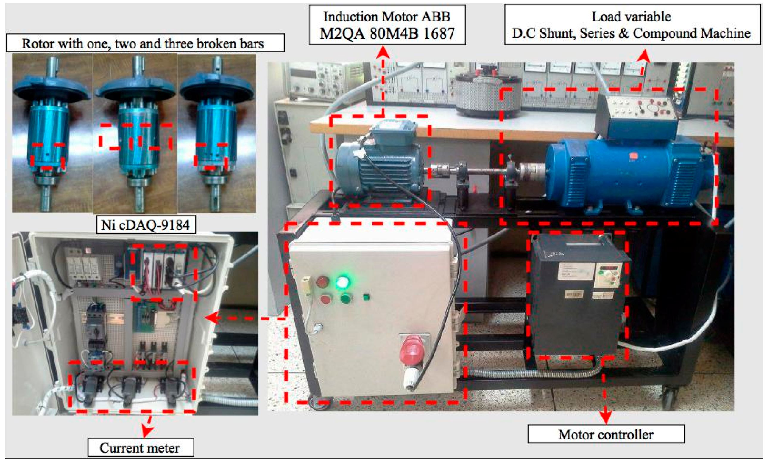
4.1. Motor Test Bench Configuration
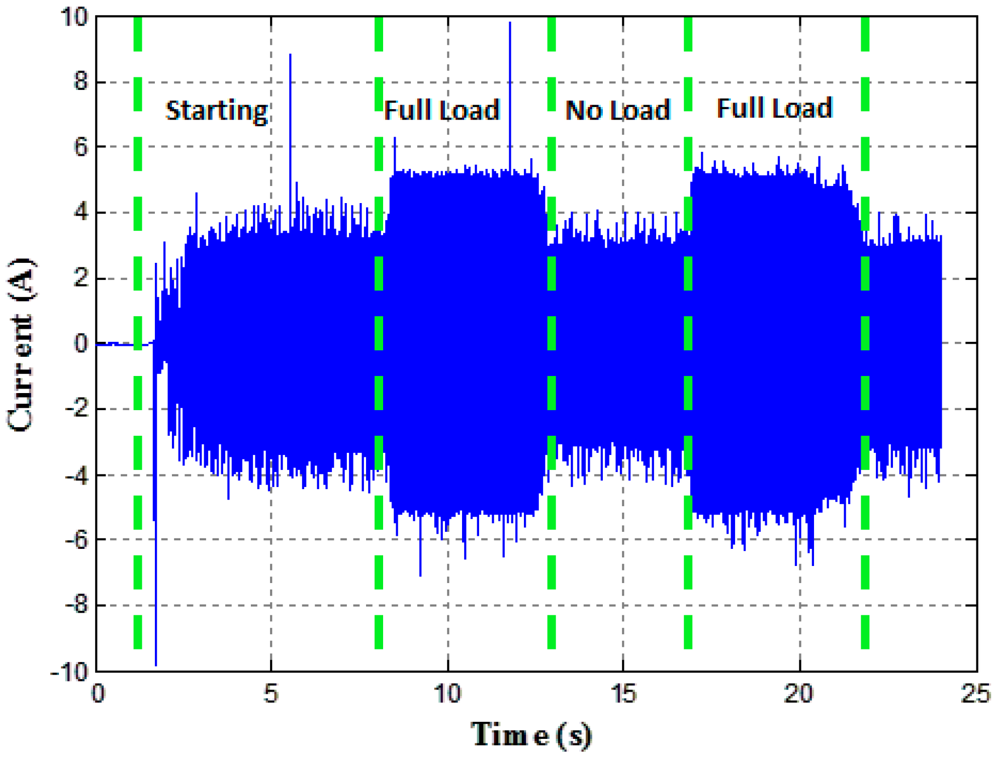
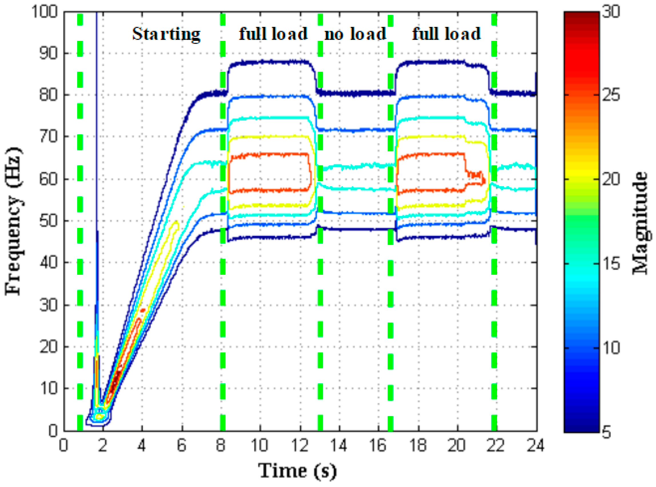
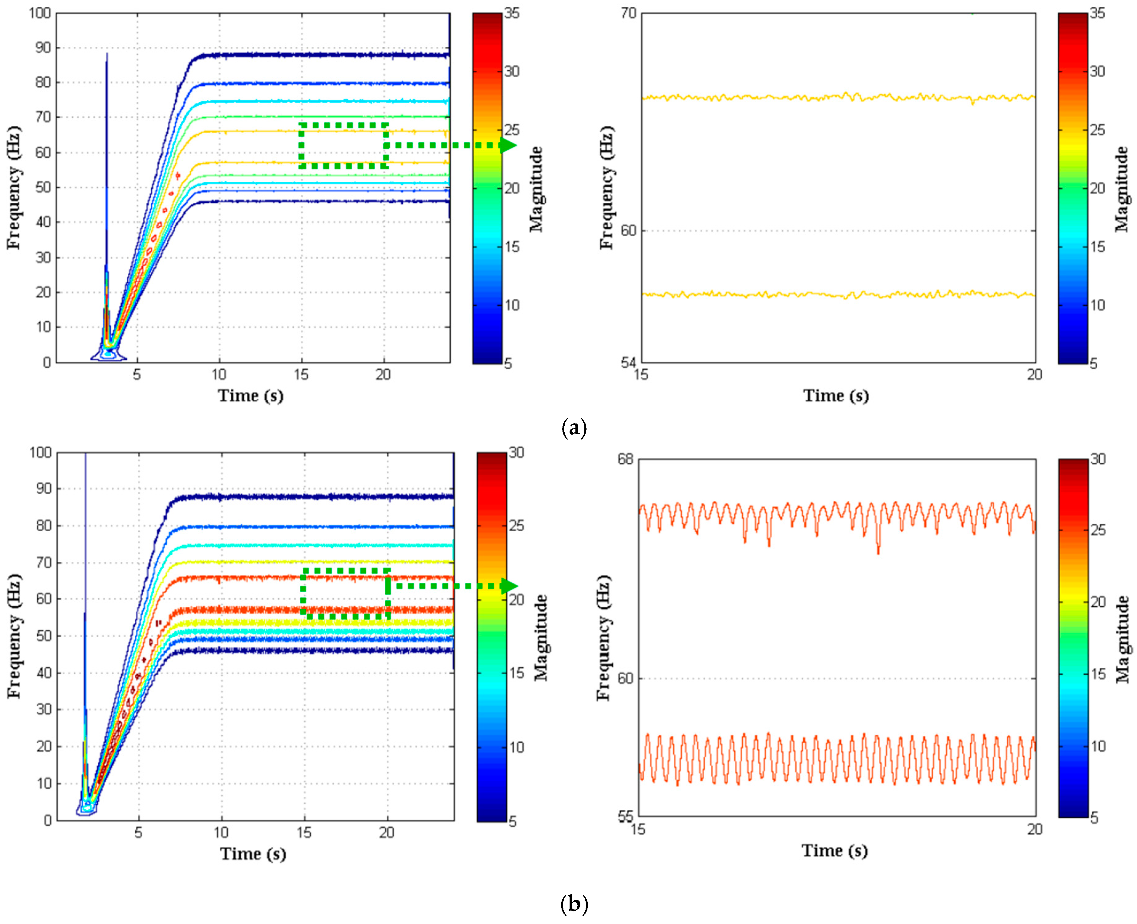
The experimental validation is accomplished in the motor test bench developed by the Electrical and Electronics Department at Universidad de las Fuerzas Armadas ESPE. The motor test bench configuration is shown in Figure 3, and includes: a three-phase squirrel cage induction motor with the features presented in Table 1; three current meters used to measure the stator current; a controllable load; a motor controller to keep constant the motor speed; and a National Instruments (NI) data acquisition board NI cDAQ-9184, which is configured to acquire the current signal data in time periods of 24 s at 25 kHz sampling rate (i.e., N = 24/(40 × 10−6) = 600,000 samples, with N being the number of samples in 24 s). Note that Morlet-CWT generates distortion at the edges of the motor current signal spectrum, since the calculation algorithm (i.e., Fourier space) considers that the studied signals are periodic. To overcome this drawback, the motor is started after a time interval of 2 s, as shown in Figure 4.
The block diagram of the proposed procedure is presented in Figure 5, which is composed of the following blocks: Block 1 performs the motor current signal acquisition automatically using the MCSA method; Block 2 analyzes the current signal by means of Continuous Wavelet Transform and obtains a graphical representation of the current signal spectrum, where fluctuations produced by broken bars can be observed; and Block 3 extracts the features of the current signal spectrum for faulty and healthy motors.
The motor test bench control and the data acquisition system are implemented through the LabVIEW® environment. The tests are performed at different speeds with full- and non-load using both a healthy motor and a faulty motor with one, two, and three broken bars. The current signal processing and the fault detection technique are developed in Matlab® (Version 9.1, MathWorks, Natick, MA, USA).

4.2. Results

The spectrum of the current signal is analyzed to compare the FFT and the continuous Morlet wavelet transform applied for broken bars detection of an induction machine. Figure 6 shows the current signal data (i.e., input data), measured through MCSA method, for a faulty motor with one broken bar working at non- and full-load during short time periods. Note that this signal data is used for the spectral analysis of both techniques.
Figure 7 shows the spectrum achieved through the FFT technique. The harmonic components related to the motor failure (i.e., one broken bar in this case) are overlapped close to the motor’s operating frequency, making fault identification difficult at a glance. Therefore, it is necessary to conduct some extra tasks to solve this problem, such as signal filtering, signal decomposition in intervals with/without load, and spectrum evaluation, all of which increase fault detection complexity. Figure 7a–c shows the spectrum obtained through the FFT technique applied to the current signal presented in Figure 6. As can be appreciated, three graphics are needed to analyze the different motor states. Figure 7a presents the current signal spectrum at motor starting, whereas Figure 7b,c show the current signal spectrum when the motor is operating at non-load and full-load, respectively. Note that the fault is visible only when a motor is analyzed at full-load. In addition, this process involves more analysis time and requires knowledge of the load at which the motor is operating (i.e., rotor slip), which increases the difficulty of fault diagnosis in an electric machine.
Conversely, Figure 8 shows the spectrum obtained by means of the continuous Morlet wavelet transform. The current signal characterization in the time-frequency spectrum is proposed to inspect, in a simple way, the disturbances that occur in a motor when it operates at non- and full-load. This spectrum is a two-dimensional graph representing the wavelet coefficients frequency, time, and amplitude achieved. On the basis of this graph, the signal spectrum can be quickly analyzed. The y-axis represents the frequency of the analyzed signal, the x-axis presents the signal time interval, and the line colors indicate the wavelet coefficient magnitude. Therefore, it is possible to detect the time intervals when the motor starts and when the motor is operating at non- and full-load. Consequently, the CWT technique concurrently facilitates and reduces the fault detection process complexity with respect to the Fourier analysis. In short, the analysis processing task and its complexity are reduced, since all information is summarized in a single spectrum.
Figure 9a,b show the spectrum of the stator current signal of a healthy motor and a faulty motor with three broken bars, respectively, operating at non-load. Both spectra have similar behavior with 6 lines representing the wavelet coefficients of motor current signal for different scales and translations, which are located at 47, 51, 55, 67, 72 and 80 Hz. Furthermore, the healthy motor exhibits small distortions in the spectrum due to noise coupled to the signal, as shown in Figure 9a, whereas the faulty motor exhibits a ripple, ∆f, in 55 Hz and 67 Hz, due to the harmonic component in the stator current induced by the fault (i.e., broken bars), as shown in Figure 9b. Conversely, the spectrum of the current signal of a faulty motor with three broken bars operating at non-load achieved through the FFT technique is shown in Figure 9c, where it can be seen that the harmonic components induced by the fault are unidentifiable.
In contrast to the aforementioned tests where a motor with non-load is analyzed, Figure 10 shows the results obtained of a motor operating at full-load. Due to the increase in the current signal amplitude, the spectrum shows 10 lines representing the wavelet coefficients. The broken bars detection can be easily performed without the use of extra tools as in other processing techniques. Note that the analysis of motors operating at non- and full-load is generalized in this study, since the main contribution of this research is fault detection when the motor is operating at non-load.
Figure 10a displays the spectrum obtained for a healthy motor, where small variations in the lines close to the motor operating frequency can be appreciated. Conversely, Figure 10b depicts the spectrum for a faulty motor with three broken bars, where the main difference with respect to the healthy motor lies in the ripple appearance at the frequency levels close to the motor operating frequency. Consequently, the failure can be identified by measuring the ripple amplitude and its oscillations. The lower sideband is specifically related to broken bars, whereas the upper sideband is related to the subsequent speed oscillation [3].
Finally, Table 2 summarizes the results obtained through the proposed method in a healthy and faulty motor with one, two and three broken bars. There is a variation in the current spectrum of ∆f = 1.41 Hz (i.e., ripple) located at the frequency band between 56 and 58.5 Hz, which is caused by a faulty motor with two broken bars. In addition, the increase in oscillation in the current spectrum is proportional to the number of broken bars (i.e., a greater number of broken bars leads to greater variation in the current spectrum, and vice versa). For instance, analyzing the frequency band between 56 and 58.5 Hz and comparing the results obtained for a motor with two broken bars, a 33.33% decrease in the oscillations for a motor with only one broken bar, and a 47.57% increase in the oscillations of for a motor with three broken bars can be determined. Furthermore, broken bar detection can be achieved by analyzing the different frequency bands presented in Table 2, where the characterization for broken bar detection is presented. This approach offers a suitable alternative for motor diagnosis and the quantification of broken bars in an induction motor.

5. Conclusions

This work has presented an alternative approach to performing the fault diagnosis of broken bars in a three-phase induction motor. The proposed approach is based on the CWT-Morlet to synthesize the motor current signal, which avoids the separate analysis of the transient and stationary states and facilitates the fault diagnosis procedure. By decomposition of the current signal into scale and translation coefficients, and the relationship between the wavelet scale and Fourier frequency, the proposed procedure is able to identify the frequency bands where variations associated with the harmonics induced by broken bar failures occur. Frequency band analysis has shown that the oscillation increase in the current spectrum is proportional to the number of broken bars. The experimental validation of the proposed procedure carried out in the motor test bench implemented at Universidad de las Fuerzas Armadas ESPE proved an efficient fault diagnosis and achieved the quantification of the number of broken bars in a three-phase induction motor. The results achieved by the wavelet transform highlight the applicability of this technique for the analysis of different electrical variables, which allow the study of different faults in electric machines.
Future work will be focused on the application of the proposed approach to perform the identification of bearing damage, short-circuit faults in windings, and eccentricity of induction machines. In addition, an extension of the proposed work will be focused on classification based on the Support Vector Machine.

Acknowledgments

This work is part of the projects No. 2013-PIC-019 and No. 2016-PIC-025 from Universidad de las Fuerzas Armadas ESPE.

Author Contributions

The authors conceived and designed the experiments; W.G.A., D.A.A. and D.S. collaborated in the projects; D.G. implemented and performed the experiments. The authors analyzed and discussed the results, wrote and revised the paper.

Conflicts of Interest

The authors declare no conflict of interest.

References

  1. Glowacz, A.; Glowacz, Z. Diagnosis of stator faults of the single-phase induction motor using acoustic signals. Appl. Acoust. 2017, 117, 20–27. [Google Scholar] [CrossRef]
  2. Puche-Panadero, R.; Pineda-Sanchez, M.; Riera-Guasp, M.; Roger-Folch, J.; Hurtado-Perez, E.; Perez-Cruz, J. Improved Resolution of the MCSA Method Via Hilbert Transform, Enabling the Diagnosis of Rotor Asymmetries at Very Low Slip. IEEE Trans. Energy Convers. 2009, 24, 52–59. [Google Scholar] [CrossRef]
  3. Nandi, S.; Toliyat, H.A.; Li, X. Condition monitoring and fault diagnosis of electrical motors—A review. IEEE Trans. Energy Convers. 2005, 20, 719–729. [Google Scholar] [CrossRef]
  4. Cusidó, J.; Romeral, L.; Ortega, J.A.; Garcia, A.; Riba, J. Signal injection as a fault detection technique. Sensors 2011, 11, 3356–3380. [Google Scholar] [CrossRef] [PubMed]
  5. Delgado, M.; Garcia, A.; Ortega, J.A.; Urresty, J.; Riba, J.R. Bearing diagnosis methodologies by means of common mode current. In Proceedings of the IEEE 13th European Conference on Power Electronics and Applications, Barcelona, Spain, 8–10 September 2009; pp. 1–10. [Google Scholar]
  6. Ceban, A.; Pusca, R.; Romary, R. Study of Rotor Faults in Induction Motors Using External Magnetic Field Analysis. IEEE Trans. Ind. Electron. 2012, 59, 2082–2093. [Google Scholar] [CrossRef]
  7. Bellini, A.; Filippetti, F.; Tassoni, C.; Capolino, G.-A. Advances in Diagnostic Techniques for Induction Machines. IEEE Trans. Ind. Electron. 2008, 55, 4109–4126. [Google Scholar] [CrossRef]
  8. Mustafa, M.O.; Nikolakopoulos, G.; Gustafsson, T. Broken bars fault diagnosis based on uncertainty bounds violation for three-phase induction motors. Int. Trans. Electr. Energy Syst. 2015, 25, 304–325. [Google Scholar] [CrossRef]
  9. Moussa, M.A.; Boucherma, M.; Khezzar, A. A Detection Method for Induction Motor Bar Fault Using Sidelobes Leakage Phenomenon of the Sliding Discrete Fourier Transform. IEEE Trans. Power Electron. 2017, 32, 5560–5572. [Google Scholar] [CrossRef]
  10. Thomson, W.T.; Fenger, M. Current signature analysis to detect induction motor faults. IEEE Ind. Appl. Mag. 2001, 7, 26–34. [Google Scholar] [CrossRef]
  11. Gyftakis, K.N.; Spyropoulos, D.V.; Kappatou, J.C.; Mitronikas, E.D. A Novel Approach for Broken Bar Fault Diagnosis in Induction Motors Through Torque Monitoring. IEEE Trans. Energy Convers. 2013, 28, 267–277. [Google Scholar] [CrossRef]
  12. Talhaoui, H.; Menacer, A.; Kessal, A.; Kechida, R. Fast Fourier and discrete wavelet transforms applied to sensorless vector control induction motor for rotor bar faults diagnosis. ISA Trans. 2014, 53, 1639–1649. [Google Scholar] [CrossRef] [PubMed]
  13. Glowacz, A.; Glowacz, Z. Diagnosis of the three-phase induction motor using thermal imaging. Infrared Phys. Technol. 2017, 81, 7–16. [Google Scholar] [CrossRef]
  14. Gaeid, K.S.; Ping, H.W.; Khalid, M.; Salih, A.L. Fault diagnosis of induction motor using MCSA and FFT. Electr. Electron. Eng. 2011, 1, 85–92. [Google Scholar]
  15. Kliman, G.B.; Stein, J. Methods of motor current signature analysis. Electr. Mach. Power Syst. 1992, 20, 463–474. [Google Scholar] [CrossRef]
  16. Elbouchikhi, E.; Choqueuse, V.; Trachi, Y.; Benbouzid, M. Induction machine bearing faults detection based on Hilbert-Huang transform. In Proceedings of the 2015 IEEE 24th International Symposium on Industrial Electronics (ISIE), Buzios, Brazil, 3–5 June 2015; pp. 843–848. [Google Scholar]
  17. Mehala, N.; Dahiya, R. Rotor faults detection in induction motor by wavelet analysis. Int. J. Eng. Sci. Technol. 2009, 1, 90–99. [Google Scholar]
  18. Nau, S.L.; Schmitz, D.; de Lima Pires, W. Methods to evaluate the quality of stator and rotor of electric motors. In Proceedings of the 2015 IEEE 10th International Symposium on Diagnostics for Electrical Machines, Power Electronics and Drives (SDEMPED), Guarda, Portugal, 1–4 September 2015; pp. 64–70. [Google Scholar]
  19. Keskes, H.; Braham, A. Recursive Undecimated Wavelet Packet Transform and DAG SVM for Induction Motor Diagnosis. IEEE Trans. Ind. Inform. 2015, 11, 1059–1066. [Google Scholar] [CrossRef]
  20. García-Escudero, L.A.; Duque-Perez, O.; Morinigo-Sotelo, D.; Perez-Alonso, M. Robust condition monitoring for early detection of broken rotor bars in induction motors. Expert Syst. Appl. 2011, 38, 2653–2660. [Google Scholar] [CrossRef]
  21. Chikouche, D.; Boukazzoula, N.; Rezki, M.; Ayad, M. Search of a robust defect signature in gear systems across adaptive Morlet wavelet of vibration signals. IET Signal Process. 2014, 8, 918–926. [Google Scholar]
  22. Garcia-Perez, A.; Romero-Troncoso, R.J.; Cabal-Yepez, E.; Osornio-Rios, R.A. The Application of High-Resolution Spectral Analysis for Identifying Multiple Combined Faults in Induction Motors. IEEE Trans. Ind. Electron. 2011, 58, 2002–2010. [Google Scholar] [CrossRef]
  23. Corral-Hernandez, J.A.; Antonino-Daviu, J.; Pons-Llinares, J.; Climente-Alarcon, V.; Frances-Galiana, V. Transient-Based Rotor Cage Assessment in Induction Motors Operating with Soft Starters. IEEE Trans. Ind. Appl. 2015, 51, 3734–3742. [Google Scholar] [CrossRef]
  24. Pons-Llinares, J.; Antonino-Daviu, J.A.; Riera-Guasp, M.; Lee, S.B.; Kang, T.; Yang, C. Advanced Induction Motor Rotor Fault Diagnosis Via Continuous and Discrete Time-Frequency Tools. IEEE Trans. Ind. Electron. 2015, 62, 1791–1802. [Google Scholar] [CrossRef]
  25. Farge, M. Wavelet Transforms and their Applications to Turbulence. Annu. Rev. Fluid Mech. 1992, 24, 395–458. [Google Scholar] [CrossRef]
  26. Torrence, C.; Compo, G.P. A Practical Guide to Wavelet Analysis. Bull. Am. Meteorol. Soc. 1998, 79, 61–78. [Google Scholar] [CrossRef]
  27. Cusido, J.; Rosero, J.A.; Cusido, M.; Garcia, A.; Ortega, J.A.; Romeral, L. On-Line System for Fault Detection in Induction Machines based on Wavelet Convolution. In Proceedings of the 2007 IEEE Power Electronics Specialists Conference, Orlando, FL, USA, 17–21 June 2007; pp. 927–932. [Google Scholar]
  28. Mehrjou, M.R.; Mariun, N.; Marhaban, M.H.; Misron, N. Evaluation of Fourier and wavelet analysis for efficient recognition of broken rotor bar in squirrel-cage induction machine. In Proceedings of the 2010 IEEE International Conference on Power and Energy, Kuala Lumpur, Malaysia, 2–4 November 2010; pp. 740–743. [Google Scholar]
  29. Ece, D.G.; Başaran, M. Condition monitoring of speed controlled induction motors using wavelet packets and discriminant analysis. Expert Syst. Appl. 2011, 38, 8079–8086. [Google Scholar] [CrossRef]
  30. Haji, M.; Toliyat, H.A. Pattern recognition-a technique for induction machines rotor broken bar detection. IEEE Trans. Energy Convers. 2001, 16, 312–317. [Google Scholar] [CrossRef]
  31. Da Silva, I.N.; Godoy, W.F.; Lopes, T.D.; Goedtel, A.; Palácios, R.H.C. Application of intelligent tools to detect and classify broken rotor bars in three-phase induction motors fed by an inverter. IET Electr. Power Appl. 2016, 10, 430–439. [Google Scholar]
  32. Karmakar, S.; Chattopadhyay, S.; Mitra, M.; Sengupta, S. Induction Motor Fault Diagnosis Approach through Current Signature Analysis; Springer: Singapore, 2016; p. 182. [Google Scholar]
  33. Hernandez, J.C.; Antonino-Daviu, J.; Martinez-Gimenez, F.; Peris, A. Comparison of different wavelet families for broken bar detection in induction motors. In Proceedings of the 2015 IEEE International Conference on Industrial Technology (ICIT), Sevilla, Spain, 17–19 March 2015; pp. 3220–3225. [Google Scholar]
  34. Rangel-Magdaleno, J.; Ramirez-Cortes, J.; Peregrina-Barreto, H. Broken bars detection on induction motor using MCSA and mathematical morphology: An experimental study. In Proceedings of the 2013 IEEE International Instrumentation and Measurement Technology Conference (I2MTC), Minneapolis, MN, USA, 6–9 May 2013; pp. 825–829. [Google Scholar]
  35. Tallam, R.M.; Habetler, T.G.; Harley, R.G. Stator winding turn-fault detection for closed-loop induction motor drives. IEEE Trans. Ind. Appl. 2003, 39, 720–724. [Google Scholar] [CrossRef]
  36. Devi, N.R.; Sarma, D.V.S.S.S.; Rao, P.V.R. Diagnosis and classification of stator winding insulation faults on a three-phase induction motor using wavelet and MNN. IEEE Trans. Dielectr. Electr. Insul. 2016, 23, 2543–2555. [Google Scholar] [CrossRef]
  37. Menacer, A.; T-Said, M.S.d.N.; Benakcha, A.H.; Drid, S. Stator current analysis of incipient fault into asynchronous motor rotor bars using Fourier fast transform. J. Electr. Eng. 2004, 55, 122–130. [Google Scholar]
  38. Ahamed, S.K.; Sarkar, A.; Mitra, M.; Sengupta, S. Detection of Induction Motor Broken Bar Fault through Envelope Analysis Using Start-Up Current. Procedia Technol. 2012, 4, 646–651. [Google Scholar] [CrossRef]
  39. Spyropoulos, D.V.; Gyftakis, K.N.; Kappatou, J.; Mitronikas, E.D. The influence of the broken bar fault on the magnetic field and electromagnetic torque in 3-phase induction motors. In Proceedings of the 2012 20th International Conference on Electrical Machines, Marseille, France, 2–5 September 2012; pp. 1868–1874. [Google Scholar]
  40. Picazo-Rodenas, M.J.; Antonino-Daviu, J.; Climente-Alarcon, V.; Royo-Pastor, R.; Mota-Villar, A. Combination of Noninvasive Approaches for General Assessment of Induction Motors. IEEE Trans. Ind. Appl. 2015, 51, 2172–2180. [Google Scholar] [CrossRef]
  41. Singh, G.; Kumar, C.A.; Naikan, V.N.A. Effectiveness of Current Envelope analysis to detect broken rotor bar and inter turn faults in an inverter fed induction motor drive. In Proceedings of the 2015 International Conference on Power and Advanced Control Engineering (ICPACE), Bengalooru, India, 12–14 August 2015; pp. 191–194. [Google Scholar]
  42. Gyftakis, K.; Antonino-Daviu, J.; Garcia-Hernandez, R.; McCulloch, M.; Howey, D.; Cardoso, A. Comparative Experimental Investigation of the Broken Bar Fault Detectability in Induction Motors. In Proceedings of the 2015 IEEE 10th International Symposium on Diagnostics for Electrical Machines, Power Electronics and Drives (SDEMPED), Guarda, Portugal, 1–4 September 2015; pp. 461–467. [Google Scholar]
  43. Sapena-Bano, A.; Perez-Cruz, J.M.J.; Pineda-Sanchez, M.; Roger-Folch, J.; Riera-Guasp, M.; Puche-Panadero, R. Harmonic order tracking analysis: A novel method for the diagnosis of induction generators. In Proceedings of the 2014 International Conference on Electrical Machines (ICEM), Berlin, Germany, 2–5 September 2014; pp. 1765–1771. [Google Scholar]
  44. Kia, S.H.; Henao, H.; Capolino, G.-A. Diagnosis of broken-bar fault in induction machines using discrete wavelet transform without slip estimation. IEEE Trans. Ind. Appl. 2009, 45, 1395–1404. [Google Scholar] [CrossRef]
  45. Mehrjou, M.R.; Mariun, N.; Karami, M.; Noor, S.B.M.; Zolfaghari, S.; Misron, N.; Kadir, M.Z.A.A.; Radzi, M.A.M.; Marhaban, M.H. Wavelet-Based Analysis of MCSA for Fault Detection in Electrical Machine. In Wavelet Transform and Some of Its Real-World Applications; InTech: Rijeka, Croatia, 2015. [Google Scholar]
  46. Ngote, N.; Ouassaid, M.; Guedira, S.; Cherkaoui, M. On the Detection of Induction-Motor Rotor Fault by the Combined ‘Time Synchronous Averaging-Discrete Wavelet Transform’ Approach. J. Electr. Eng. Technol. 2015, 10, 2315–2325. [Google Scholar] [CrossRef]
  47. Li, D.Z.; Wang, W.; Ismail, F. A Spectrum Synch Technique for Induction Motor Health Condition Monitoring. IEEE Trans. Energy Convers. 2015, 30, 1348–1355. [Google Scholar] [CrossRef]
  48. El Bouchikhi, E.H.; Choqueuse, V.; Benbouzid, M. Induction machine faults detection using stator current parametric spectral estimation. Mech. Syst. Signal Process. 2015, 52–53, 447–464. [Google Scholar] [CrossRef]
  49. Pons-Llinares, J.; Antonino-Daviu, J.A.; Riera-Guasp, M.; Pineda-Sanchez, M.; Climente-Alarcon, V. Induction Motor Diagnosis Based on a Transient Current Analytic Wavelet Transform via Frequency B-Splines. IEEE Trans. Ind. Electron. 2011, 58, 1530–1544. [Google Scholar] [CrossRef]
  50. Komorowski, D.; Pietraszek, S. The Use of Continuous Wavelet Transform Based on the Fast Fourier Transform in the Analysis of Multi-channel Electrogastrography Recordings. J. Med. Syst. 2016, 40, 10. [Google Scholar] [CrossRef] [PubMed]
Figure 1. Morlet mother wavelet signal.
Mca 22 00030 g001
Figure 2. Broken fault detection algorithm through Motor Current Signature Analysis (MCSA) method and Morlet-CWT (Continuous Wavelet Transform) technique.
Mca 22 00030 g002
Figure 3. Three-phase motor test bench configuration, components and description.
Mca 22 00030 g003
Figure 4. Data acquisition time scheme.
Mca 22 00030 g004
Figure 5. Fault diagnosis process block diagram.
Mca 22 00030 g005
Figure 6. Signal data acquired using the MCSA method for a faulty motor with one broken bar operating at non- and full-load.
Mca 22 00030 g006
Figure 7. Current signal spectrum obtained using the Fast Fourier Transform (FFT) technique for a faulty motor with one broken bar: (a) FFT spectrum for motor starting interval; (b) FFT spectrum for non-load operation interval; and (c) FFT spectrum for full-load operation interval.
Mca 22 00030 g007
Figure 8. Spectrum of the current signal obtained using the CWT technique for a faulty motor with one broken bar operating at non- and full-load.
Mca 22 00030 g008
Figure 9. Spectrum of the current signal obtained using the CWT technique for a motor operating at non-load (a) healthy motor; (b) faulty motor with three broken bars; and (c) spectrum of the current signal obtained through the FFT technique of a faulty motor with three broken bars operating at non-load.
Mca 22 00030 g009
Figure 10. Spectrum of the current signal obtained using the CWT technique for a motor operating at full-load (a) healthy motor and (b) faulty motor with three broken bars.
Mca 22 00030 g010
Table 1. Induction machine specifications.
DescriptionValueUnit
BrandABB
Rated power1Hp
Rated current3.4A
Conection typeDelta
Rated voltage220V
Supply frequency60Hz
Nominal speed1705Rpm
Torque4.2Nm
Moment of inertia0.00174kg·m2
Pole pairs2
Number of bars22
Table 2. Frequency bands associated with motor failures caused by broken bars when operating at full-load.
Number of Broken BarsFrequency Bands
56–58.5 Hz52.8–54.8 Hz50.5–52.5 Hz48.5–50 Hz
056.98 < f < 57.5553.34 < f < 53.8551.12 < f < 51.548.9 < f < 49.3
f = 0.57f = 0.51f = 0.42f = 0.41
157.41 < f < 58.3553.5 < f < 54.551.2 < f < 51.848.9 < f < 49.5
f = 0.94f = 0.98f = 0.58f = 0.59
257.02 < f < 58.4353.2 < f < 54.651 < f < 51.948.7 < f < 49.6
f = 1.41 f = 1.40f = 0.93f = 0.89
356.23 < f < 58.3552.82 < f < 54.7950.7 < f < 51.248.5 < f < 49.8
f = 2.08f = 1.97f = 1.41f = 1.32

