Article

Parameters Optimization of a Hydraulic Buffer System for Belt Arrestor in Downward Belt Conveyors

School of Mechatronic Engineering, China University of Mining and Technology, No. 1 Daxue Road, Xuzhou 221116, China
*
Author to whom correspondence should be addressed.
Math. Comput. Appl. 2016, 21(4), 42; https://doi.org/10.3390/mca21040042
Submission received: 8 August 2016 / Revised: 8 October 2016 / Accepted: 10 October 2016 / Published: 19 October 2016

Abstract

:
Hydraulic buffer systems play a significant role in energy absorption and improving belt arrest reliability in downward belt conveyors. In order give hydraulic buffer systems more preferable buffer properties, a parameters optimization method based on a reference model is proposed. Firstly, the working principle of a hydraulic buffer system for a belt arrestor is provided. Secondly, the mathematical model of the system is built and a reference model of buffer chamber pressure is constructed utilizing a second-order system. Furthermore, a genetic algorithm is introduced to optimize the system parameters. Finally, some simulation examples are carried out on the Simulink software. The simulation results show that the pressure peak in buffer process can drop down and that pressure fluctuation in buffer end processes decrease substantially after optimization. The parameters optimization method for hydraulic buffer systems is applicable to different structure parameters of the buffer cylinder.

1. Introduction

The belt conveyor plays a significant role in large transmission industries, especially in coal mining [1,2]. As the main conveyor equipment, if the conveyor belt breaks during operating process, the energy of the conveyor belt with a heavy load is released for a moment. The belt then slows down rapidly under its own gravity, the gravity of the load and their kinetic energy, which may lead to damages of the conveyor and other equipment or casualties. Therefore, conveyor belt protector equipment is regularly paid considerable attention by many scholars.
With the rapid development of modern industry, the belt conveyor is developing in the direction of heavy loads, high speeds and large angles [3,4]. Compared with upward belt conveyors, the broken belt has enormous kinetic energy in downward belt conveyors because belt normal motion and slip broken belt direction are consistent. Thus, once the conveyor belt is arrested, the energy of belt and load will have a great impact and shock on the belt arrestor and conveyor, which is likely to result in a second belt break and other damages. Hence, the belt arresting ability of an upward belt conveyor cannot meet the needs of a downward belt conveyor.
Bearing the above observations in mind, a hydraulic buffer system is designed and applied to the belt arrestor to solve the problems above. The rest of this paper is organized as follows. In Section 2, some related systems are outlined based on literature. The working principle of a hydraulic buffer system of belt arrestor for downward belt conveyors is provided in Section 3. In Section 4, a parameters optimization method based on genetic algorithm is presented. In Section 5, simulation examples are carried out. Our conclusions and future work are summarized in Section 6.

2. Literature Review

Recent literature relevant to this paper is mainly concerned with two research streams: belt arrestors and hydraulic buffer devices. In this section, we try to summarize the relevant publications.

2.1. Belt Arrestors

In recent years, many researchers have done studies on belt arrestors in the event of belt breaks. In [5], Barnard invented a conveyor belt arrestor, especially for use with inclined conveyor belts. The conveyor belt was captured by a reaction means and a wedging structure actuated by a torsion spring. In [6], Viviers proposed a conveyor arrestor system. The system can arrest the conveyor belt by two arrestors having moveable arresting structures and either of the arresting structures has activating means. In [7], Li et al. put forward a wedge-shape belt arrestor for upward belt conveyors, which has been applied in coal mines. In [8], Yin et al. designed a novel double belt arrestor, which can arrest upward and downward belts respectively. In [9], Ma et al. studied the dynamic characteristics of belt conveyors during belt rupture through building a finite element model of a belt conveyor based on AMESIM software and the optimal capturing broken-belt was confirmed. In [10,11], Zhang et al. presented an electro-hydraulic control type capture device solution and estimated the response time after analyzing a kinematic model of the device. In [12], Du et al. designed a wedge-shaped belt arrestor driven by hydraulic pressure and determined the optimal self-locking angle of wedge as 12°. In [13], Pang et al. designed a hydraulic belt arrestor system based on the differential circuit of the cylinder and rapid fluid replacement of the accumulator. The hydraulic system can shorten the time of belt arrest. In [14], Li et al. used ADAMS and AMESIM software to verify the rationality of a full-face wedge-shaped belt arrestor and its hydraulic driven system. In [15], Zhang et al. studied a both-side-revolve belt arrestor of an upward belt conveyor. In [16], Liu et al. designed a hydraulic launch belt capturing system by utilizing the advantages of a two-way cartridge valve and accumulator.

2.2. Hydraulic Buffer Device

Until now, only some researchers used spring to absorb the impact and shock of the belt arrestor. In [17], Tian et al. designed a novel belt arrestor, mainly applying the spring to reduce the impact caused by catching the belt. In [18], Zhou et al. developed a safety test system belt arrestor with deceleration function utilizing a spring. The system can test the performance of the catching belt and improve the safety operating coefficient of the belt conveyor. Compared with a spring buffer device, a hydraulic buffer device has advantages of high buffer efficiency and stable buffer performance. In hydraulic cylinder-inside buffer devices, scholars mostly studied the buffer device applied in vehicles. In [19], Wang et al. researched a rail vehicle’s axle-box hydraulic damper and established an improved full parametric model, considering variable viscous damping, comprehensive stiffness and small mounting clearance. In [20], Ramos et al. presented a method to predict the performance of automotive twin tube shock absorbers and used different shock absorbers to verify the validity of predictions. In [21], Alonso and Comas proposed an analytical method to determine the damping force of a twin tube shock absorber, considering fluid and chambers compressibility effects and fluid cavitation. In [22], Alonso and Comas analyzed the force variation due to thermal effects caused by energy dissipation within the damper and further calculated the shock absorber temperature field. In [23], Qian et al. studied the shock absorber applied to a train and simulated the effect of the valve parameters of absorber on the train dynamics characteristics.
In recent years, some researchers have started to focus on the cylinder-outside buffer of short buffer strokes. In [24], Zhou applied a throttling buffer and accumulator throttling buffer to the stroke end of a hydraulic cylinder for 13.5 MN hydraulic press. In [25], Yang used an accumulator and a relief valve to absorb the impact of a hydraulic cylinder in the horizontal direction for a heavy load forging manipulator.

2.3. Discussion

Although many approaches were proposed for belt arrestor in the above literature, they have some common disadvantages summarized as follows. Firstly, most of researchers only presented their methods for upward belt arrestors. However, the trigger principle of the upward belt arrestor is carried out according to the normal running direction which is consistent with the break direction, while the trigger principle of the downward belt arrestor is realized according to the inconsistent direction of the normal running and belt break. Thus, the upward belt arrestors cannot be used in a downward belt conveyor. Secondly, the belt arrestors were designed without considering impact and shock of catching the broken belt. The impact of belt and load cannot be ignored, especially for downward belt conveyors. Thirdly, although the hydraulic cylinder-inside buffer technology was mature, it has some shortcomings of complex internal structure, difficult processing and limited buffer capacity. Therefore, the hydraulic cylinder-inside buffer is not suitable for absorbing impact in belt conveyors. Finally, a genetic algorithm has not yet been used to optimize the system parameters of the hydraulic buffer system for belt arrestor in downward belt conveyors.
In order to tackle the above problems, this paper designs a hydraulic cylinder-outside buffer system for absorbing impact and shock of the belt arrestor in a downward belt conveyor. In order to give the hydraulic buffer system more preferable buffer properties, a reference model of the system is conducted and a parameters optimization method is presented to optimize the system parameters based on a genetic algorithm. Some examples are carried out to verify the feasibility and applicability of the proposed optimization method for hydraulic buffer system.

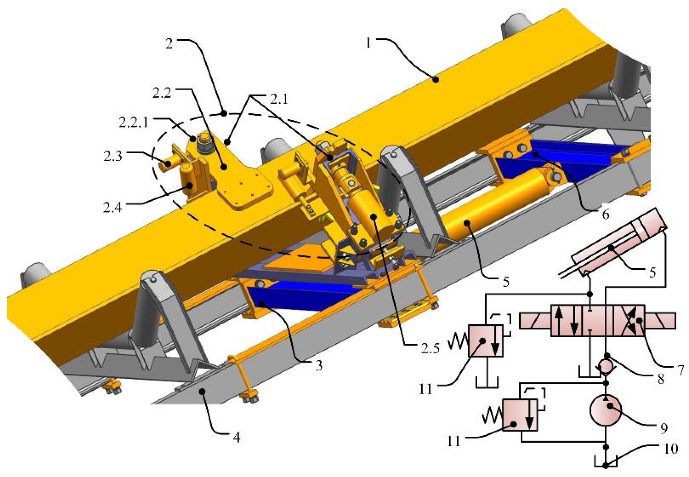
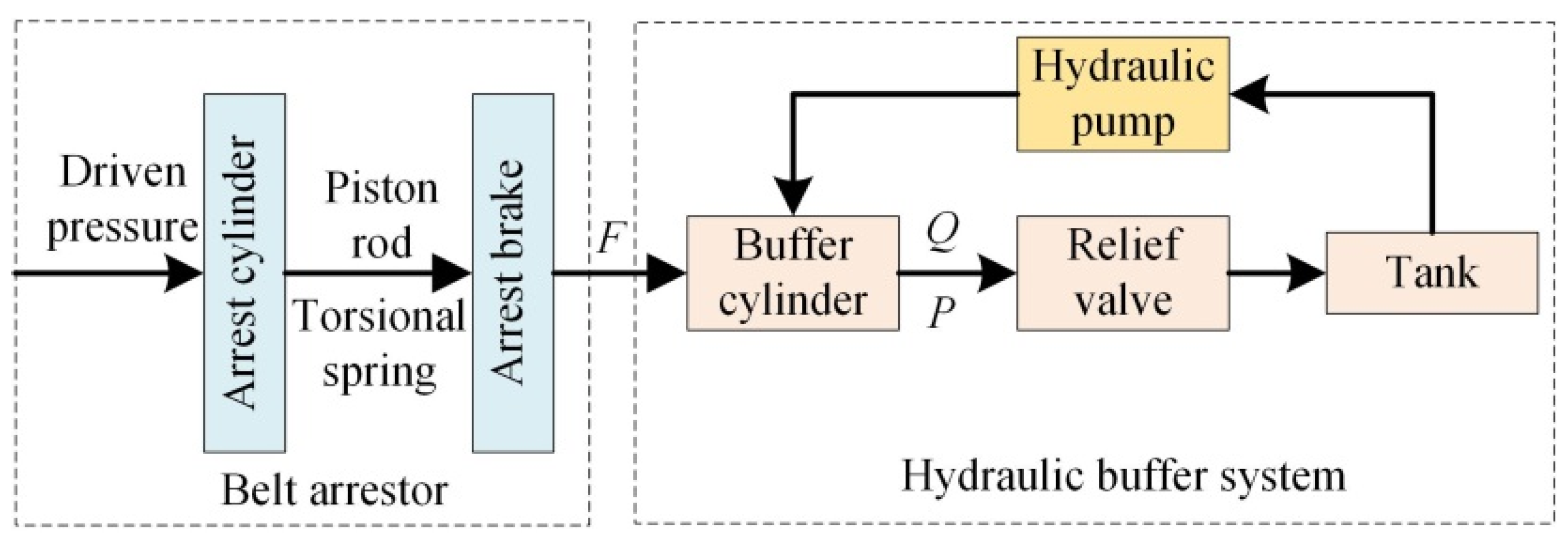
3. The Working Principle of the Hydraulic Buffer System

In this section, we will present the working principle of the hydraulic buffer system for the belt arrestor in a downward belt conveyor.
As shown in Figure 1, the hydraulic buffer device mainly consists of arrestor, buffer cylinder and relief valve. The belt arrestor is constructed by an arrest cylinder, arrest brake and trigger latch. The buffer cylinder is fastened on the conveyor rail by a buffer cylinder-fixed device. The piston rod of the buffer cylinder and the belt arrestor are connected. The piston rod of the capturing cylinder and arrest brake are connected. The relief valve is connected with the rod cavity of the buffer cylinder [26].
Figure 2 demonstrates the hydraulic buffer system and belt arrestor when the belt conveyor is running normally. Firstly, the arrest cylinder is extended to ensure that the trigger latch is inserted into the groove of the arrest brake and the torsional spring is tightened. Secondly, the arrest brake can be rotated by the torsional spring in case the trigger latch is out of the arrest brake. Finally, the hydraulic pump provides oil for the rod chamber to make the piston rod fully retracted and the buffer displacement is the stroke of the buffer cylinder.
Once the belt is broken, the arrest brake will be shifted down by the piston rod of the arrest cylinder and rotated to the position by the torsional spring until the conveyor belt is captured. Then, the piston of the buffer cylinder can be driven by the belt arrestor. Thus, the kinetic energy of belt and load is absorbed. The hydraulic oil of the buffer cavity is compressed by extending the piston rod. Hydraulic pressure of the buffer cavity generates a damping force to prevent the belt arrestor running fast. When hydraulic pressure rises to the opening pressure of the relief valve, the hydraulic oil will flow out of the buffer cavity. The opening of the relief valve plays a protective role in the buffer chamber. The pressure regulating of the relief valve keeps buffer pressure constant, so the downward broken-belt and arrestor will slow down at approximately uniform speed reduction until stopping (as shown in Figure 1).

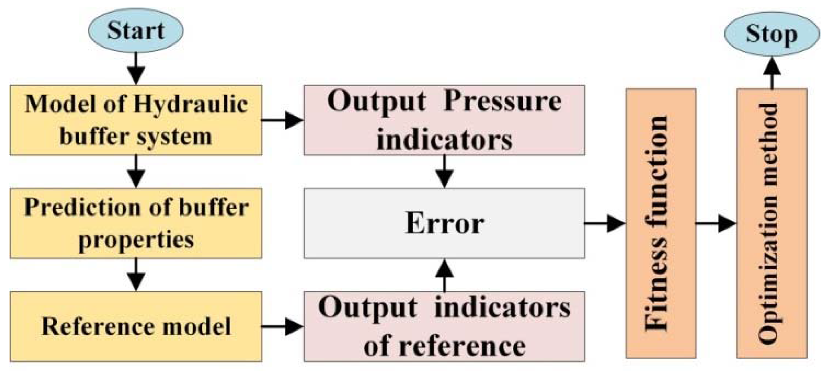
4. Parameters Optimization Method of the Hydraulic Buffer System

In this section, the parameters optimization method is presented according to the processes shown in Figure 3. Firstly, a mathematical and simulation model of the hydraulic buffer system is built. Secondly, the reference model is constructed by utilizing a two-order system with the objective function established based on Simulink. Finally, a genetic algorithm is introduced.

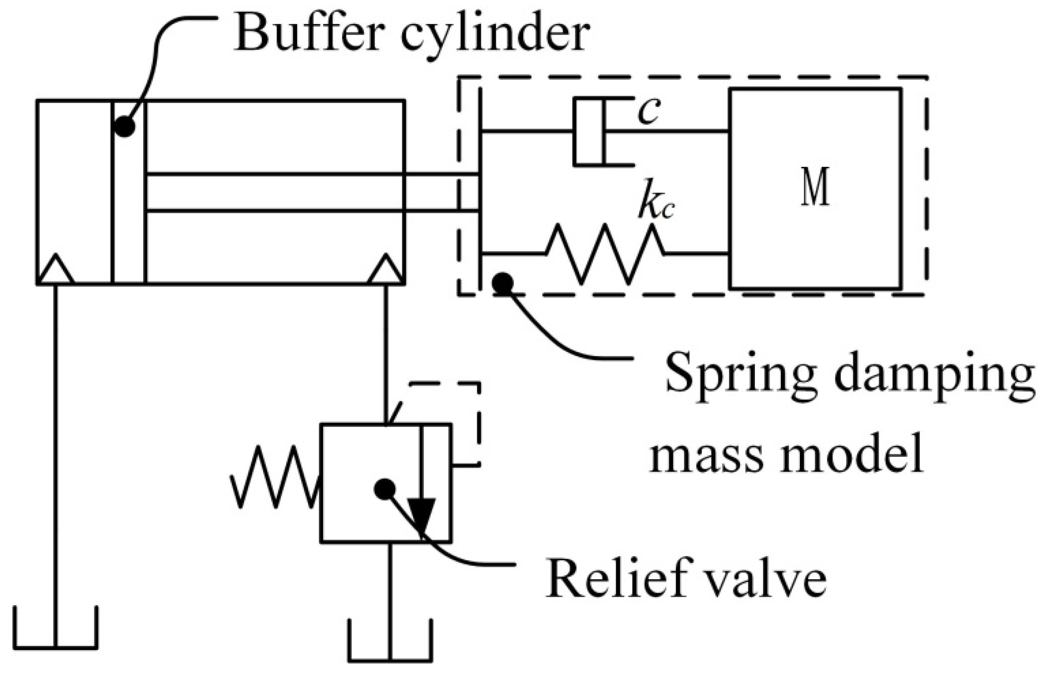
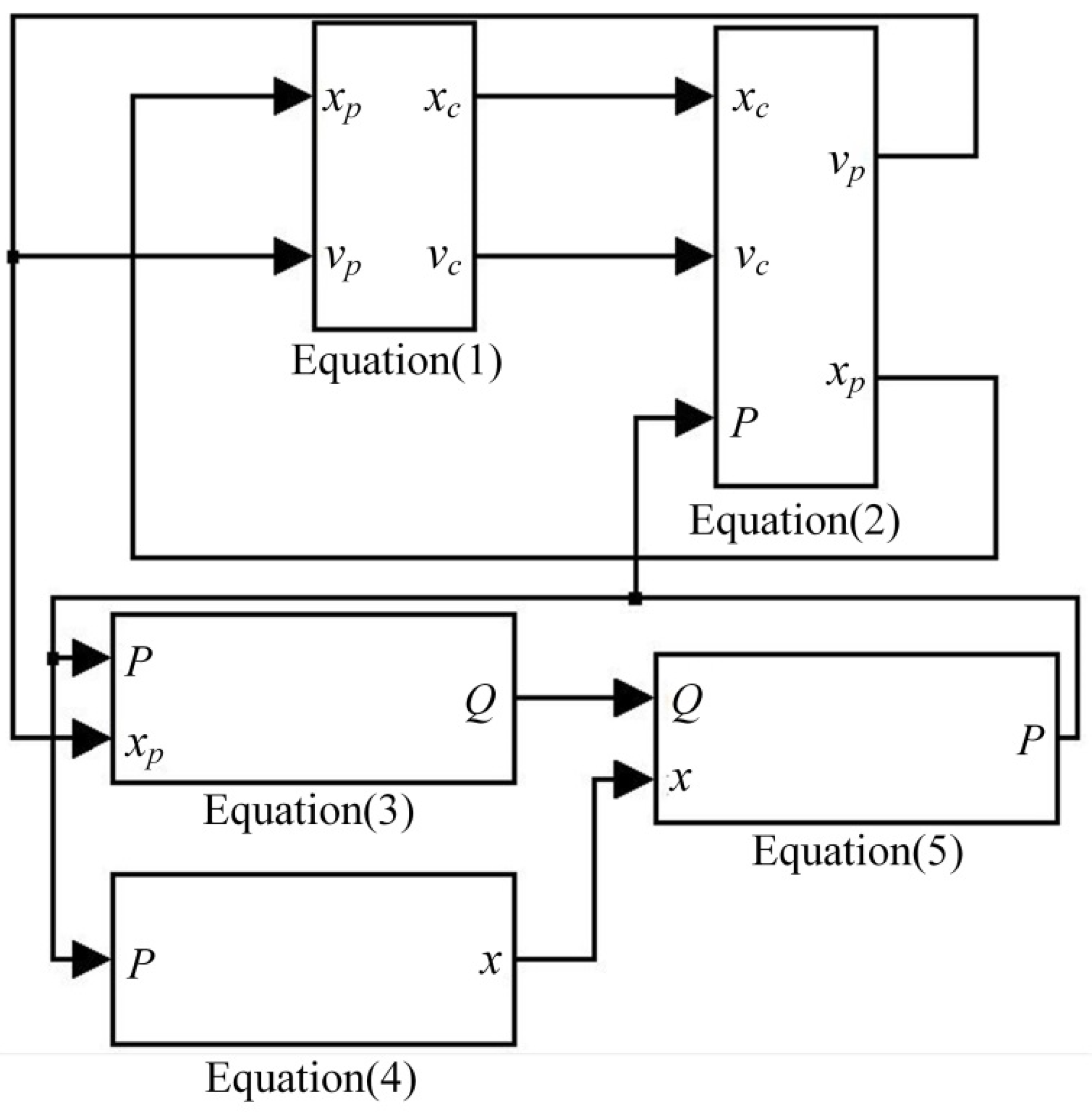
4.1. Model of the Hydraulic Buffer System

The model of the hydraulic buffer system can be simplified as shown in Figure 4. The model of the buffer system in buffer process is equivalent to a spring damping mass model [27].
The dynamic model of the conveyor belt is provided as follows:
M x ¨ c = M g   s i n   θ F f k c ( x c x p ) c ( x ˙ c x ˙ p )
where {M} is the mass of the conveyor belt, Ff is the resistance of the buffer process, θ is the lean angle of the conveyor, {xc} are the displacement of the belt, {xp} are the displacement of the piston rod, kc is the equivalent stiffness of the conveyer belt, and c is the equivalent damping coefficient of the conveyer belt.
The piston rod force balance mode of buffer cylinder is given as follows:
m p x ¨ p = m p g sin θ + k c ( x c x p ) + c ( x ˙ c x ˙ p ) B p x ˙ p P A p
where {mp} is the mass of the belt arrestor and the piston rod, Bp is the damping coefficient of the damping cylinder, P is the hydraulic buffer pressure, and Ap is the section area of the piston rod.
The flow continuity equation of the buffer cylinder is presented as follows:
A p x ˙ p V p β d P d t = Q
where Vp is the real-time volume of the buffer cavity, V p = A p ( L 0 x p ) , L0 is the stroke of the buffer cylinder, β is the elastic modulus of the hydraulic oil, and Q is the flow out of the buffer cavity.
Ignoring transient and steady-state fluid dynamics of the relief valve, the force balance equation of the relief valve spool mass is given as follows:
m x ¨ = P A B x ˙ K ( x 0 + x )
where A is the spool sectional area of the relief valve, B is the spool damping coefficient of the relief valve, K is the spring stiffness of the relief valve, x is the spool displacement, and x0 is the spring pre-compression.
Assuming that the hydraulic oil of the buffer cavity flows out of the spool of the relief valve fully, Q is given by [28].
Q = C A 0 2 P ρ x
where A0 is the spool throttle area of the relief valve and A0 is simplified as A 0 = π x   sin   ( α ) .
According to Equations (1)–(5), the simulation model of the buffer is built based on Simulink software as shown in Figure 5.

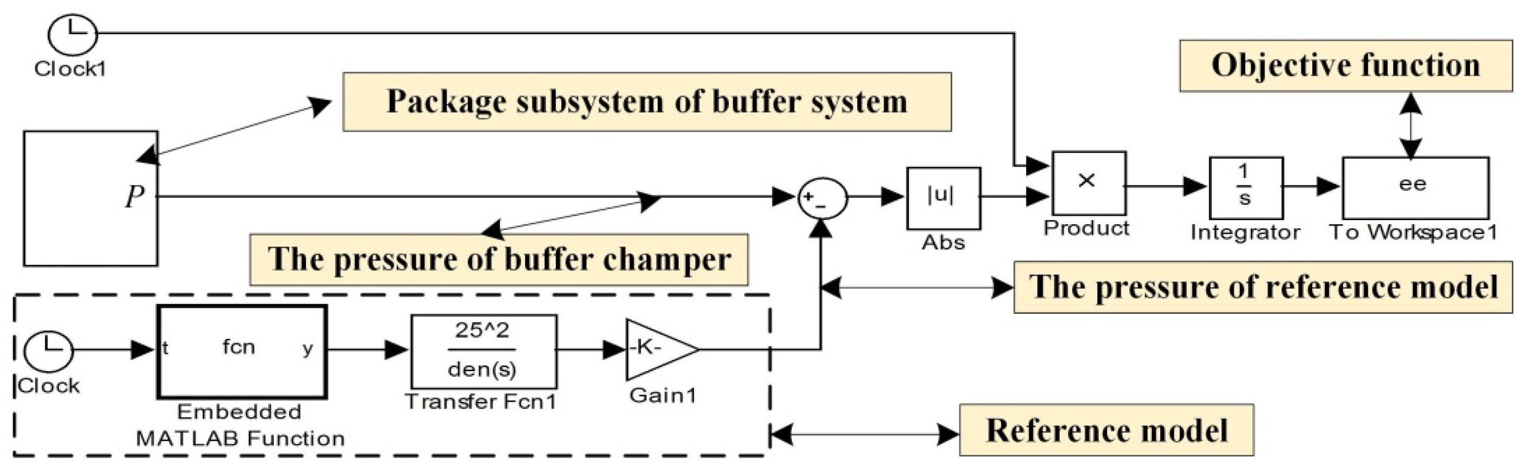
4.2. Reference Model of the Hydraulic Buffer System

The kinetic and gravitational energy of the belt arrestor are absorbed by the buffer cylinder based on the energy conservation law. The energy conservation law in the buffer process is provided as follows:
E = 1 2 M v 0 2 + M g x c sin θ = Δ E + 0 x p P A p d x p
where ΔE is the loss of energy resulting from the slippage of the conveyor belt when capturing the broken belt, assuming that the conveyor belt does no slippage.
According to the components and characters of the hydraulic buffer system, we can analyze that the ideal buffer performance is as follows: in the buffer process, the belt arrestor slows down at approximately uniform speed, that is, the reduced acceleration is nearly constant or the hydraulic pressure of the buffer chamber remains constant as far as possible. Thus, we can take the ideal pressure of the buffer chamber as the reference model of the buffer system.
The pressure of the buffer chamber has two processes. One is in the buffer process, when the hydraulic pressure should provide the adequate reduced acceleration to make the conveyor belt and arrestor stop in the range of buffer cylinder stroke. Another is in buffer end process with relief valve closing, when the hydraulic pressure balances the gravity gliding force of belt and arrestor. Thus, the ideal pressure should have minimal overshoot in the buffer process and little fluctuation in the buffer end process.
The hydraulic pressures in the buffer process and buffer end process are calculated refering to Equations (7) and (8).
1 2 M v 0 2 + M g x sin θ = p A p x
M g sin θ = p 0 A p
Once the pressure of the buffer process is determined, the reduced acceleration and the buffer time can be deduced based on the dynamic knowledge and the rise time of the relief valve.
The ideal model of the buffer cavity pressure can be constructed by a typical two-order system since the pressure character of the relief valve is a two-order system [29]. This system is shown in Equation (9).
G ( s ) = w n 2 s 2 + 2 ζ w n + w n 2
where the parameter wn is the natural frequency and ζ is the damping ratio.
The damping ratio of the two-order system is chosen as 0.707 and the natural frequency wn is chosen as the rise time of the pressure response for the relief valve.
When ζ < 1, the rise time tr gives Equation (10).
t r = π cos 1 ζ w n 1 ζ 2
Then, w n is presented as follows:
w n = π cos 1 ζ t r 1 ζ 2 = 3.2858 × 1 t r
The pressure rise time of the relief valve is set as 13 ms and w n can be calculated as 25.
As a result, the ideal reference of the hydraulic buffer system is deduced as shown in Figure 6.
In order to build the objective function, the simulation model is further packaged as a Simulink module of output pressure. The fitness function of this optimization is determined as a time error absolute integral (ITAE) performance as follows:
J I T A E = 0 t t | e ( t ) | d t
where e(t) is the error of the simulated hydraulic pressure of the hydraulic buffer system and the reference pressure and t is the simulation time.
In summary, the objective function model is constructed as shown in Figure 6 based on the reference model and the simulation model [30,31].

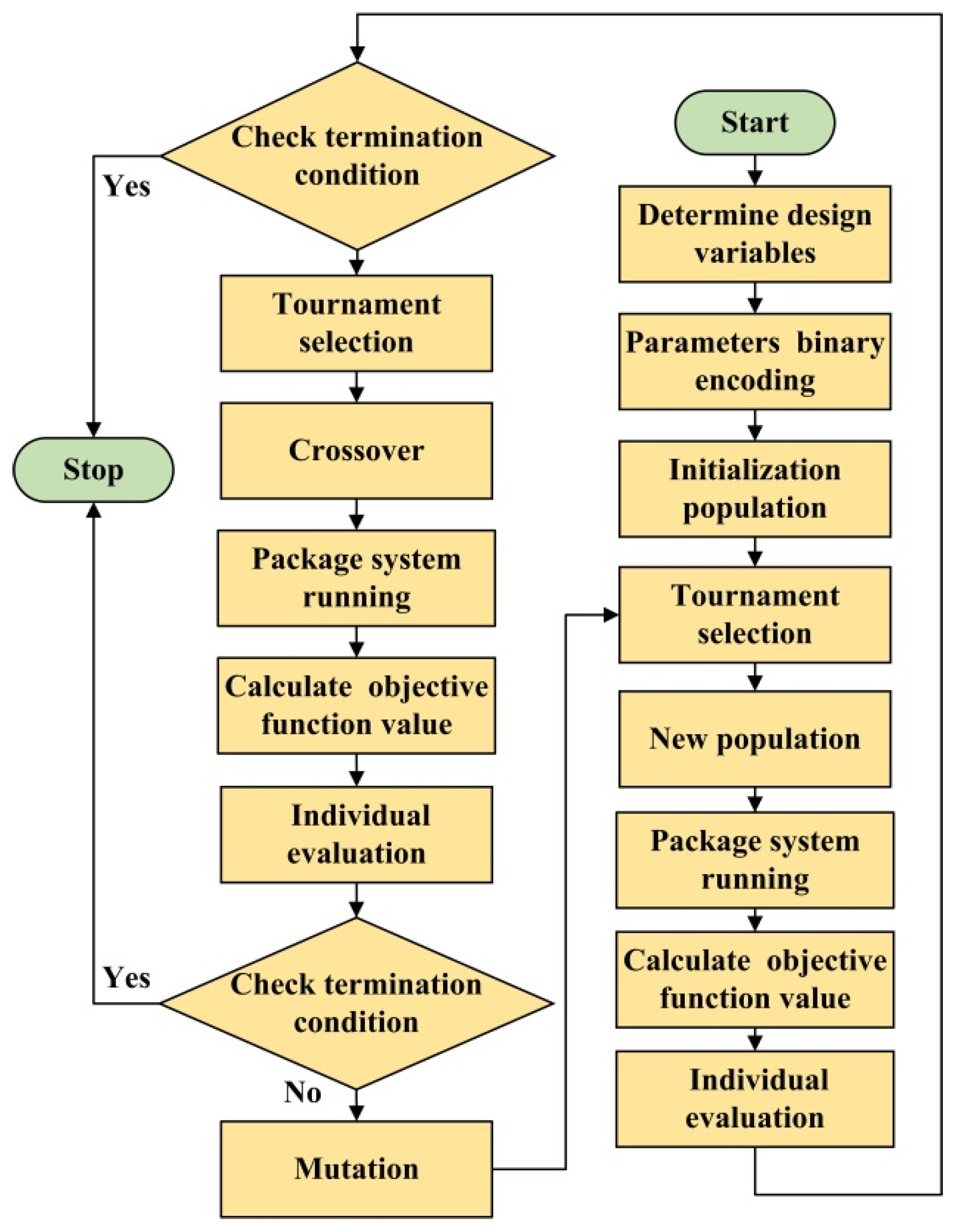
4.3. Optimization Algorithm

According to above method, the reference model can be easily constructed under the prameters of the buffer cylinder provided. The common optimization algorithms include simulated annealing algorithm, genetic algorithm, ant colony algorithm and so on. Genetic algorithm is a global optimization algorithm, which can search for optimal solutions for global variables at the same time. Compared with the traditional optimization method, a genetic algorithm is a random search algorithm referring to natural selection and natural genetic mechanisms and provides a better solution for multi-variable and nonlinear problems [32]. Therefore, the parameters of the relief valve are optimized based on a genetic algorithm. The proposed approach is coded easily on the computer and the flowchart is summarized in Figure 7.
Step 1: Refering to the construction of the reference model, the design variables are determined as the spool diameter, the spring stiffness and the spring pre-compression of the relief valve.
Step 2: The spool diameter of the relief valve, the spring stiffness and the spring pre-compression are denoted by 10-bit binary numbers respectively. Thus, three word strings compose a 30-bit chromosome, indicating a binary code of the spool diameter of the relief valve, the spring stiffness and the spring pre-compression from left to right.
Step 3: In the ranges of the three design variables, the initial population is generated as the encoding shown in Step 2. An individual represents a set of design variables.
Step 4: The individual evaluation is in terms of fitness function. The fitness function is the objective function as shown in Figure 6.
Step 5: The genetic operators are chosen as tournament selection. Namely, k (k ≥ 1) individuals are chosen for evaluation and comparison, of which having the highest value of fitness function is inherited by the next generation. The process is repeated N times to produce a new population.
Step 6: The individuals generated in Step 5 are crossed and mutated in a constant probability.
Step 7: Check whether the fitness conditions are satisfied, if yes, the operation stops, otherwise Steps 4–6 are repeated.

5. Simulation Example

5.1. Preparing Work

In order to construct the reference model of the hydraulic buffer system, we take the DTIIA (where D refers to a type of belt conveyor, T indicates the universal type and IIA indicates a new series)-type belt as a research object, of which the relevant parameters are shown in Table 1 [33]. The belt arrestor is installed at the distance of 30 m, considering the randomness of the belt break and economic effectiveness of coal mines.
According to the data shown in Table 1, the mass of the broken belt and load is calculated as 6258.3 kg. The diameter of the piston is adopted as 0.1 m, the diameter of the piston rod as 0.05 m and the displacement of the piston rod as 1.5 m for the buffer cylinder. Thus, the hydrualic pressures in the buffer process and in the buffer end process are 9.23 MPa and 3.56 MPa respectively. Thus, the reference model can be establish according to section 4.2 as shown in Figure 8.
The main parameters of the hydraulic buffer system are shown in Table 2 [34,35].
The optimization ranges of design variables D, x0, K are as follows, D: 0–50 mm; x0: 0–100 mm; and K: 0–1000 N/mm.
In this optimization, the population size n is 80, the crossover probability Pc is 0.8, the mutation probability Pm is 0.1, and the maximum number of iterations N is 100 [36,37].

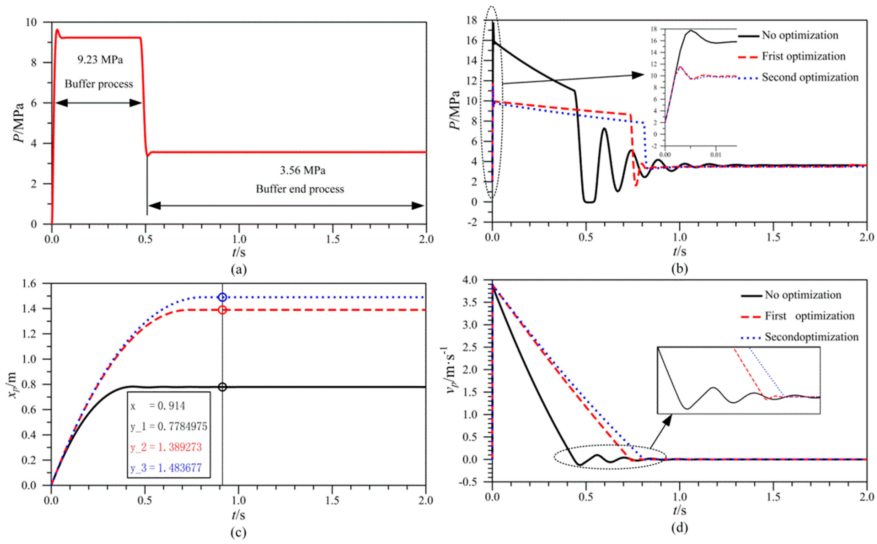
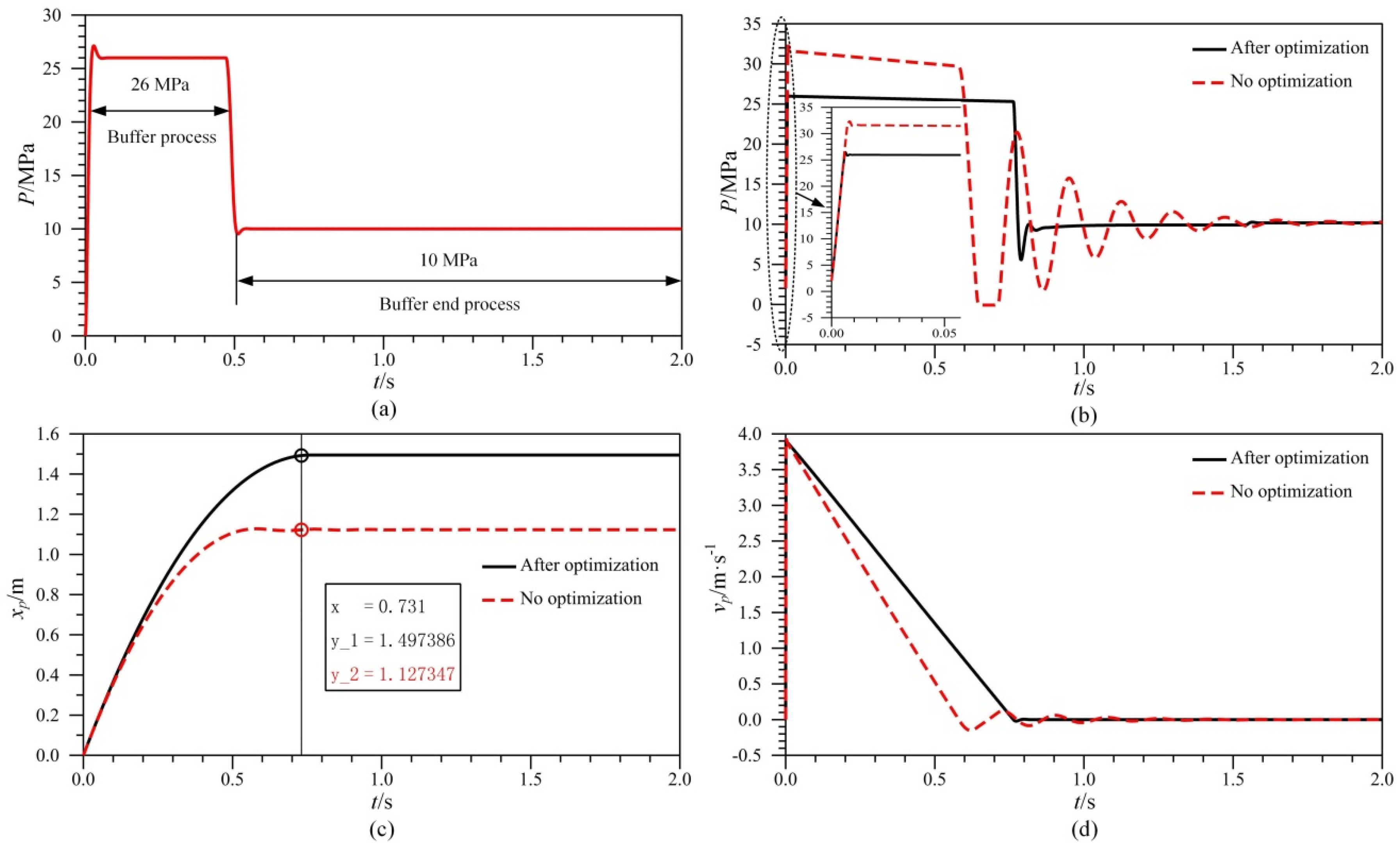
5.2. Simulation Results and Analysis

After parameters optimization, we obtain the optimized design variables as shown in Table 3. Then, the curves of pressure of the buffer chamber, the displacement and velocity of the piston rod are shown in Figure 8b–d. Figure 8a is the reference model for when the piston diameter of the buffer cylinder d1 is set as 100 mm and the piston rod diameter of the buffer cylinder d2 is set as 50 mm.
From Figure 8b–d, the conclusion is drawn that buffer properties of the hydraulic buffer system are improved after two optimizations. The second optimization is better and a favourable buffer performance is as follows: the pressure peak in the buffer process decreases from 18 MPa to 12 MPa, the displacement of the piston rod increases from 0.78 m to 1.48 m, the buffer time increases from 0.45 s to 0.8 s, and the pressure fluctuation and speed oscillations of the piston rod in the buffer end process decrease.
In order to verify the flexibility of the proposed optimization method based on different reference models, simulation examples in a different stroke of the buffer cylinder are carried out as follows. The diameter of the piston is selected as 87 mm, the diameter of the piston rod is selected as 70 mm and the buffer maximum stroke is unchanged. The reference model is built according to section 4.2 as shown in Figure 9a. After optimization, the diameter of the relief valve is 47 mm, the spring stiffness is 670 N/mm and the spring pre-compression is 65.5 mm. The optimized properties curves in different buffer cylinders are shown in Figure 9b–d.
As shown in Figure 9a–d, the optimization results show that the peak of buffer pressure in the buffer process decreases, the pressure fluctuation in the buffer end process lessens, the speed vibration of the piston rod drops, the displacement of the piston rod increases and the buffer time gets longer. The optimization verifies the flexibility of the proposed optimization method based on different reference models.

6. Conclusions and Future Work

This paper described the hydraulic cylinder-outside buffer system for the belt arrestor in a downward belt conveyor and utilized the relief valve to absorb the kinetic energy of belt and load. In order to achieve better buffer properties, the working principle of the hydraulic buffer system for the belt arrestor was provided and the mathematical framework was established. Then, the ideal pressure of a reference model was constructed and further a parameters optimization method of hydraulic buffer system was proposed. Finally, some simulation examples were carried out based on Simulink and a genetic algorithm to verify the feasibility of the proposed optimization method.
However, there are also some limitations and issues in this paper listed as follows: (1) the mathematical model of the hydraulic buffer system is sufficiently accurate but does not consider the steady and transient fluid dynamic of the relief valve; (2) the optimization results lack experimental verification; (3) the genetic algorithm without improvement is used only in the parameters optimization.
In future studies, the authors plan to build a mathematical model of the system considering more factors, use a different optimization algorithm to optimize the system parameters, and further set up the laboratory table to verify the simulated results and optimized results.

Acknowledgments

The support of Production-Study-Research Cooperation Projects Foundation of Jiangsu Province (No. BY2015023-09) and the Priority Academic Program Development (PAPD) of Jiangsu Higher Education Institutions in carrying out this research are gratefully acknowledged.

Author Contributions

Yinwei Yang and Wenjun Yin contributed the new processing method; Zhanyu Wang and Jing Xu designed the simulations; Wenjun Yin wrote the paper.

Conflicts of Interest

The authors declare no conflict of interest.

References

  1. Lodewijks, G. Two decades dynamics of belt conveyor systems. Bulk Solids Hand. 2002, 22, 124–132. [Google Scholar]
  2. Li, J.X.; Kou, Z.M.; Jing, Y.U. The characteristic analysis and experimental research of hydraulic speeding soft brake for downward belt conveyor. J. China Coal Soc. 2013, 38, 1697–1702. [Google Scholar]
  3. Harrison, A. Power Oscillation Mechanisms in Booster Conveyors. In MECH’91Australia; Engineering for a Competitive World; International Mechanical Engineering Congress and Exhibition, Sydney, Australia, 8–12 July 1991; pp. 89–95.
  4. Zhu, L.P.; Jiang, W.L. Study on typical belt conveyor in coal mine of China. J. China Coal Soc. 2010, 35, 1916–1920. [Google Scholar]
  5. Barnard, H. Conveyor Belt Arrestor. US20060118393, 8 June 2006. [Google Scholar]
  6. Viviers, P. Conveyor Belt Arrestor System. WO/2016/055882A2, 14 April 2016. [Google Scholar]
  7. Li, Y.W.; Miao, Y.J.; Wang, X.Y.; Chen, Y.G. Development of SPDB-I type broken belt protector for uphill belt conveyor. Coal Mine Mach. 2006, 27, 477–479. [Google Scholar]
  8. Yin, W.J.; Du, C.T.; Gao, P.; Han, Z.D.; Tan, C.; Liu, X.H.; Yu, H. Double Belt Catching Device Suitable for Large Angle Belt Conveyor. CN205076429U, 9 March 2016. [Google Scholar]
  9. Ma, H.W.; Li, D.S.; Zhang, X.H.; Mao, Q.H. Dynamic simulation analysis of belt rupture for belt conveyor. Appl. Mech. Mater. 2013, 313, 1120–1124. [Google Scholar] [CrossRef]
  10. Zhang, X.H.; Ma, H.W.; Zhang, D.W.; Mao, Q.H.; Chen, W.H. Analysis and design an electro-hydraulic type belt capture device for belt conveyor. Appl. Mech. Mater. 2012, 121, 1901–1905. [Google Scholar] [CrossRef]
  11. Zhang, X.H. Development of new type of electro-hydraulic belt capture device for belt conveyor. Mach. Tool Hydra 2012, 40, 1–3. [Google Scholar] [CrossRef]
  12. Du, J.W.; Li, J.X.; Kou, Z.M. Simulation and test study of wedgy broken-belt catching device. Min. Process. Equip. 2014, 42, 65–68. [Google Scholar]
  13. Pang, X.X.; Kou, Z.M.; Li, J.X. Numerical analysis and test study on hydraulic injection circuit for broken-belt catcher. Min. Process. Equip. 2015, 43, 65–70. [Google Scholar]
  14. Li, J.X.; Kou, Z.M.; Du, J.W. Co-simulation and experimental research of wedge broken-belt catching device. Open Mech. Eng. J. 2014, 8, 358–263. [Google Scholar]
  15. Zhang, X.; Qi, Y.; Jia, Q. The both-side-revolve broken belt catching machine. Int. J. Coal Sci. Technol. 2009, 34, 845–848. [Google Scholar]
  16. Liu, X.R.; Ma, L.; Ma, X.H. New hydraulic system of broken belt capture equipment. Chin. Hydraul. Pneum. 2016, 67–71. [Google Scholar] [CrossRef]
  17. Tian, S.T.; Bao, J.H.; Jiang, X.; Du, Y.X.; Zhu, K.H.; Li, Y.H.; Cheng, X.N. Broken Belt Protection Device with Deceleration Function. CN103818699, 18 November 2015. [Google Scholar]
  18. Zhou, M.S.; Sun, B.W.; Yuan, Z.G.; Li, G.; Yan, Z.Y. The Comprehensive Performance of Safety Testing System for Buffer Broken Belt Catching Device with Buffer Device. CN103708208, 9 September 2015. [Google Scholar]
  19. Wang, W.L.; Yu, D.S.; Zhou, Z. In-service parametric modelling a rail vehicle’s axle-box hydraulic damper for high-speed transit problems. Mech. Syst. Signal Process. 2015, 62, 517–533. [Google Scholar] [CrossRef]
  20. Ramos, J.C.; Rivas, A.; Biera, J.; Sacramento, G.; Sala, J.A. Development of a thermal model for automotive twin-tube shock absorbers. Appl. Therm. Eng. 2005, 25, 1836–1853. [Google Scholar] [CrossRef]
  21. Alonso, M.; Comas, Á. Modelling a twin tube cavitating shock absorber. Proc. Inst. Mech. Eng. Part D J. Automob. Eng. 2006, 220, 1031–1040. [Google Scholar] [CrossRef]
  22. Alonso, M.; Comas, Á. Thermal model of a twin-tube cavitating shock absorber. Proc. Inst. Mech. Eng. Part D J. Automob. Eng. 2008, 222, 1955–1964. [Google Scholar] [CrossRef]
  23. Qian, X.; Qing, H.L.; Chan, C. The influence of lateral shock absorber valve parameters on vehicle dynamic performance. J. Mech. Sci. Technol. 2015, 29, 1907–1911. [Google Scholar]
  24. Zhou, J.Y. Resaearch on the Working Condition of Hydraulic Press Return Based on Electro-Hydraulic Proportional Contrl. Master’s Thesis, Degree-Changan University, Changan, China, 2012. [Google Scholar]
  25. Yang, Q.S. Study on Buffering Principle and Dynamic Characteristics of Heavy load Forging Manipulator. Master’s Thesis, Degree-Chongqing University, Chongqing, China, 2013. [Google Scholar]
  26. Yang, Y.W.; Wang, Z.B.; Si, L.; Tan, C.; Han, Z.D.; Zheng, R.Y.; Liu, X.H.; Zhao, L.L.; Liang, B.; Wang, Q.G. Method for Absorbing Energy and Energy Absorbing Device of down Belt Conveyor. CN104097920, 15 October 2014. [Google Scholar]
  27. Chen, W.; Li, X. Model reduction for large rigid-flexible coupling belt conveyor system based on balanced realization. J. China Coal Soc. 2014, 39, 569–575. [Google Scholar]
  28. Licsko, G.; Champneys, A.; Hos, C. Nonlinear analysis of a single stage pressure relief valve. Int. J. Appl. Math. 2009, 39, 12–26. [Google Scholar]
  29. Eyres, R.D.; Champneys, A.R.; Lieven, N.A.J. Modelling and dynamic response of a damper with relief valve. Nonlinear Dyn. 2005, 40, 119–147. [Google Scholar] [CrossRef]
  30. Sugai, H.; Nonami, K. Reference model following sliding mode control for hydraulic mine detection hexapod robot. Trans. Jpn. Soc. Mech. Eng. C 2006, 72, 2829–2837. [Google Scholar] [CrossRef]
  31. Aly, A.A. Model reference PID control of an electro-hydraulic drive. Int. J. Intell. Syst. Appl. 2012, 4, 24–32. [Google Scholar] [CrossRef]
  32. Tao, M.; Zhao, Y.; Wang, G.W. Parameter optimization of sound absorption layer based on genetic algrithm. J. Vib. Shock 2014, 33, 20–25. [Google Scholar]
  33. Beijing Materials Handling Research Institute; Wuhan Feng Fan Technology Development Co., Ltd. DTII (A) Type Belt Conveyor Design Manual, 2nd ed.; Metallurgical Industry Press: China, 2013; pp. 65–112. [Google Scholar]
  34. Zhou, B.; Geng, Y.; Hung, X.T. Global sensitivity analysis of hydraulic system parameters to a hydraulically interconnected suspension’s dynamic response. J. Vib. Shock 2015, 34, 72–76. [Google Scholar]
  35. Wang, W.P.; Zhang, H.L.; Zhang, G.L. Analysis of port leakage on direct operted relief valve under foundation vibration. J. Zhejiang Univ. (Eng. Sci.) 2015, 49, 1160–1165. [Google Scholar]
  36. Wei, G.; Yang, Z.G.; Li, Q.L. Areodynamic optimization method for car body based on process costing genetic algrithm. J. Jilin Univ. (Eng. Technol. Ed.) 2014, 44, 1578–1582. [Google Scholar]
  37. Liang, C.Y.; Lü, P.; Ji, J.W.; Wang, X. Optimization of PID parameters for electro-hydraulic variable rate fertilization system based on genetic algorithm. Trans. Chin. Soc. Agric. Mach. 2013, 44, 89–93. [Google Scholar]
Figure 1. The working principle of the hydraulic buffer system. 1, Broken-belt of downward belt conveyor; 2, Belt arrestor; 2.1, Torsional spring; 2.2, Arrestor brake; 2.2.1, Groove; 2.3, Trigger latch; 2.4, Limiting mechanism; 2.5, Arrestor cylinder; 3, Buffer motion link; 4, Conveyor rail; 5, Buffer cylinder; 6, Buffer cylinder fixed device; 7, Solenoid valve; 8, Check valve; 9. Pump; 10, Oil tank; 11, Relief valve.
Mca 21 00042 g001
Figure 2. The buffer process for the belt arrestor. F corresponds to the arrest force of arrestor, P is the pressure of buffer chamber and Q is the flow out of the buffer cavity.
Mca 21 00042 g002
Figure 3. The procedure of the parameters optimization method.
Mca 21 00042 g003
Figure 4. The model of the hydraulic buffer system. C corresponds to the equivalent damping coefficient of the conveyer belt, kc is the equivalent stiffness of the conveyer belt and M indicates the mass of the conveyor belt.
Mca 21 00042 g004
Figure 5. The simulation model of the hydraulic buffer system. P corresponds to the pressure of buffer chamber, Q is the flow out of the buffer cavity, x is the spool displacement, xp indicates the displacement of the piston rod, xc is the displacement of belt, vc corresponds to the speed of the belt and vp is the speed of the piston rod.
Mca 21 00042 g005
Figure 6. The objective function based on Simulink.
Mca 21 00042 g006
Figure 7. The parameters optimization flowchart based on a genetic algorithm.
Mca 21 00042 g007
Figure 8. The optimized performance curves: (a) The pressure reference model of d1 = 100 mm, d2 = 50 mm; (b) The buffer pressure; (c) The displacement of piston rod and (d) The speed of piston rod.
Mca 21 00042 g008
Figure 9. The optimized performance curves in different buffer cylinder: (a) The pressure reference model of d1 = 87 mm, d2 = 70 mm; (b) The buffer pressure; (c) The displacement of piston rod and (d) The speed of piston rod.
Mca 21 00042 g009
Table 1. The parameters of the conveyor belt.
ParametersUnits
Spacing of bearing roller1.5 m
Belt speed (v0)4 m/s
Delivery capacity2500 t/h
Unit mass of belt35 kg
Unit mass of load173.61 kg
Equivalent stiffness107 N/m/s
Equivalent damping coefficient106 N/m/s
Lean angle of the belt conveyor20°
Table 2. The parameters of the hydraulic buffer system.
ComponentsParametersSymbolsUnits
Buffer cylinderInitial pressureP02 MPa
Damping coefficientBp50 N/m/s
Relief valveDiameter of spoolD0.03 m
Damping coefficientB10 N/m/s
Spring stiffnessK600 N/mm
Spring pre compressionx00.035 m
Hydraulic oilDensityρ870 kg/m3
Elastic modulusE1.4 × 109 MPa
Table 3. The optimized results.
Optimization ResultsSymbolsFrist OptimizationSecond Optimization
UnitsIntegersUnitsIntegers
Spool diameter of relief valveD43.684440.2740
Spring stiffnessK204.29204410.15410
Spring pre-compressionx063.466324.3124

