Experimental Study on the Reinforcement Mechanism of Segmented Split Grouting in a Soft Filling Medium

1
School of Transportation and Civil Engineering, Shandong Jiaotong University, 5001 Haitang Road, Ji’nan 250023, China
2
Geotechnical and Structural Engineering Research Center, Shandong University, Ji’nan 250061, China
*
Author to whom correspondence should be addressed.
Processes 2018, 6(8), 131; https://doi.org/10.3390/pr6080131
Submission received: 25 July 2018
/
Revised: 10 August 2018
/
Accepted: 13 August 2018
/
Published: 17 August 2018
(This article belongs to the Special Issue Fluid Flow in Fractured Porous Media)
Abstract
:Subsection split grouting technology can effectively improve the grouting efficiency and homogeneity of grouting in a target reinforcement area. It is therefore necessary to clarify the reinforcement mechanism and characteristics of the soft filling medium under the condition of split grouting. A three-dimensional grouting simulation test of segmented split grouting in a soft filling medium was conducted. The distribution characteristics and thicknesses of the grouting veins were obtained under the condition of segmented grouting. The mechanical mechanism of segmented split grouting reinforcement, based on the distribution characteristics of different grouting veins, was revealed. After grouting, a uniaxial compression test and an indoor permeation test were conducted. Based on the method of the region-weighted average, the corresponding permeability coefficient and the elastic modulus of each splitting-compaction region were obtained. The quantitative relationship between the mechanical properties and the impermeability of the soft filling medium before and after grouting was established. The results revealed that three different types of veins were formed as the distance from the grouting holes increased; namely, skeleton veins, cross-grid grouting veins, and parallel dispersed grouting veins. The thicknesses of the grouting veins decreased gradually, whereas the number of grouting veins increased. Moreover, the strikes of the grouting vein exhibited increased randomness. The reinforcement effect of segmental split grouting on soft filling media was mainly confirmed by the skeleton support and compaction. The elastic modulus of the grouting reinforcement solid increased on average by a factor that was greater than 100, and the permeability coefficient decreased on average by a factor that was greater than 40 in the direction of the parallel grouting vein with the most impermeable solid. The research results may be helpful in the investigation of the split grouting reinforcement mechanism under the condition of segmented grouting.
1. Introduction
Grouting [1,2,3] is increasingly and widely being used in underground engineering, to effectively strengthen soft rock and soil. The reinforcement mode of the fault-fracture zone and the quaternary topsoil layer, which are composed of a soft filling medium [4], are usually dominated by fracturing grouting [5]. Moreover, the mechanical properties and impenetrability performance of the soil can be significantly improved by grouting [3]. In the grouting processes, split grouting technology [6] can effectively improve the grouting efficiency when the method of single drilling and multiple grouting is adopted. In addition, it can significantly improve the homogeneity of grouting in a target reinforcement area [7]. However, the grouting reinforcement mechanism and simulation test research of the segmented grouting do not meet the requirements of engineering.
At present, many scholars have conducted numerous studies on the split grouting of soft filling mediums. In a theoretical study, Zhang et al. [8] considered the effect of an asymmetrical load, and obtained the analytical solution of splitting-opening pressure. Based on the flat slit model, Li Shucai and Sun Feng et al. [9,10,11,12] established a split grouting diffusion equation for different constitutive models, and a relationship between the grouting pressure or slurry viscosity and the diffusion radius of the slurry. Based on a hypothesis that the semi-infinite space of the injected medium on both sides of the grouting vein was subjected to a uniform force, Zhang Qingsong et al. [13] considered the coupling effect between the slurry flow field and the stress field of the injected medium, and established a spatial distribution equation for the width of the splitting channel. In experimental research, Zhang Lianzhen [14] developed a two-dimensional visualization split grouting simulation test device to study the split grouting mechanism of water-rich sands. The spatial attenuation characteristics of the thickness of the split grouting vein and the approximate influence range of the split grouting were obtained. Li Peng et al. [15,16] reported the improvement of the mechanical properties of a fractured mud medium before and after split grouting. However, the focus of the study was on the splitting-opening pressure [17], the relationship between the diffusion distance [18] and pressure, and the effect of single split grouting. There are few discussions on the spatial distribution and the thickness variation of the grouting veins [19], and the reinforcement that is caused by segmental split grouting.
To obtain the reinforcement characteristics of the soft filling medium under the condition of segmented split grouting, a three-dimensional grouting simulation test system was developed, which could realize segmented split grouting. A simulation test was conducted with a typical soft filling medium of the F2 fault shale filling of the Yonglian Tunnel in the Jilian Expressway, Jiangxi Province, China The reinforcement mechanism under the condition of segmented split grouting was studied. The distribution characteristics and the thickness variation of the grouting veins were obtained. The mechanism of segmental split grouting reinforcement was revealed. A uniaxial compression test and indoor penetration test were carried out by the grouting reinforcement solid in different splitting and compacting areas, and the corresponding permeability coefficient and elastic modulus of different splitting and compacting areas were obtained. Based on the methods of the regional weighted average [20], a quantitative relationship between the mechanical properties and the impermeability of the soft filling media before and after grouting was established.
2. Three-Dimensional Grouting Simulation Test System
The segmental split grouting simulation test system mainly consisted of a simulation test frame and a grouting module. The test system could realize segmental split grouting in a soft filling medium. Moreover, it could also be used to excavate, to obtain the distribution characteristics and the thickness of the grouting veins, and sampling to analyze the grouting reinforcement effect.
2.1. The Simulation Test Frame System
In order to expediently install, disassemble, observe, and sample, a simulation test frame was designed by stratified combination. It consisted of four rings with inner diameters of 1.5 m and heights of 30 cm, as shown in Figure 1. The material of the rings was high-strength steel, and they were connected to each other by high-strength bolts.
2.2. Grouting Module
The grouting module included an internal preset device and an external grouting support system. As presented in Figure 2a, the internal preset device included grouting holes, a preset grouting pipe, and a pressure bearing separator. The diameter of the preset grouting pipe was 20 mm, and it was composed of a galvanized steel pipe with overflow holes arranged at intervals. The grout was injected into the ground layer through the overflow hole under the grouting pressure. As presented in Figure 2b, the pressure-bearing separator included a diffuser-bearing body and a waterproof sand bag. The waterproof sand bag was filled with sand to prevent the passage of the slurry during the grouting process.
The external grouting supporting system included a grouting pump, a grouting pipe, and a slurry mixer. To obtain medium pressure and high pressure grouting, a pneumatic grouting pump and a manual grouting pump were used for the experiment.
3. The Experiment Design for Grouting
3.1. Test Target
- The thickness variation characteristics and the spatial distribution of the grouting veins along the direction of grout migration were obtained.
- The mechanical parameters and permeability coefficient of the injected media before and after grouting were tested, and the quantitative relationship between the mechanical properties and permeability coefficient of the soft filling medium before and after the grouting was established.
3.2. Segmented Split Grouting Process
The segmented split grouting process was as follows. Firstly, the grouting pipe was vertically arranged in the simulation test frame, as shown in Figure 3. The grouting work was divided into three segmental grouting works by the pressure-bearing separator, and the grouting was begun from the bottom up. Then, before a segmental grouting work, the separator above the grouting pipe of this segmental grouting work was closed. When the segmental grouting work was finished and the slurry was consolidated, the waterproof sand bag in the pressure bearing separator was destroyed manually to allow the slurry to pass through. Next, the next segment grouting was carried out, so the grout could enter the injected medium from the overflow hole of the next section of the grouting pipe. Finally, three segmental grouting works were finished, the experiment was set for 14 days, and then it was excavated.
3.3. Design of Filling Scheme
The fault muddy filling was used as the filling medium in this experiment, which was sourced from the F2 fault of the Yonglian Tunnel in the Jilian Expressway, Jiangxi Province, China [21]. The basic parameters are presented in Table 1.
First, before filling, the side walls of the model test stand were smoothed using glass glue. To simulate the real conditions of the tunnel fault, the soft filling medium was divided into eight layers into the mold, and then these were artificially compacted. Finally, when the filling was completed, glass glue was used to fill the gap between the inside and the filling of the model frame, to prevent the gap from becoming the dominant channel in the grouting.
3.4. Selection of Grouting Parameters
3.4.1. Selection of Grouting Pressure
The grouting pressure range was 0–1 MPa, and the grouting rate was 0–5 L/min. The grouting end standard were as follows: the grouting volume of each section was 20–40 kg, and the pressure of the external pressure gauge was a maximum of 1 MPa.
3.4.2. Selection of Grouting Material
The grouting material in this experiment consisted of Ordinary Portland cement (P.O 42.5) and a new special grouting material GT-1 [22,23]. GT-1 was self-developed by Shandong University, and it is composed of cement, polymer, dispersant, accelerator, early strength agent, pumping aid, and a defoamer. GT-1 has a quick setting effect and a higher strength in the early stages. In the grouting process, GT-1 was mixed with P.O 42.5 slurry at a certain volume ratio to form a new C-GT slurry, and it was injected into the stratum. In this experiment, the ratio of C-GT was 1:1. The basic parameters of the C-GT slurry are presented in Table 2.
3.4.3. Design of Slurry Color
To clearly determine the process of slurry migration and to compare the changes in the thicknesses of the grouting veins in different segmented split grouts, three kinds of color slurries were developed; namely, original, yellow, and red. The grouting parameters are shown in Table 3.
4. Experiment Result Analysis
The experimental results were analyzed from two aspects of distribution characteristics and thickness, as well as the grouting reinforcement effect. The distribution characteristics and the thicknesses of the grouting veins of the soft filling medium were observed and measured, obtaining the distribution characteristics and the thickness variation of the grouting veins under the condition of segmented grouting. In the aspects of the grouting reinforcement effect, the soft filling medium was sampled before and after grouting, and the uniaxial compression test and the indoor penetration test were carried out to measure the mechanical properties and the permeabilities of the samples. The changes of the elastic modulus and the permeability coefficient before and after grouting were compared. The test results were as follows.
4.1. Distribution Characteristics and Thickness Analysis of Grouting Vein
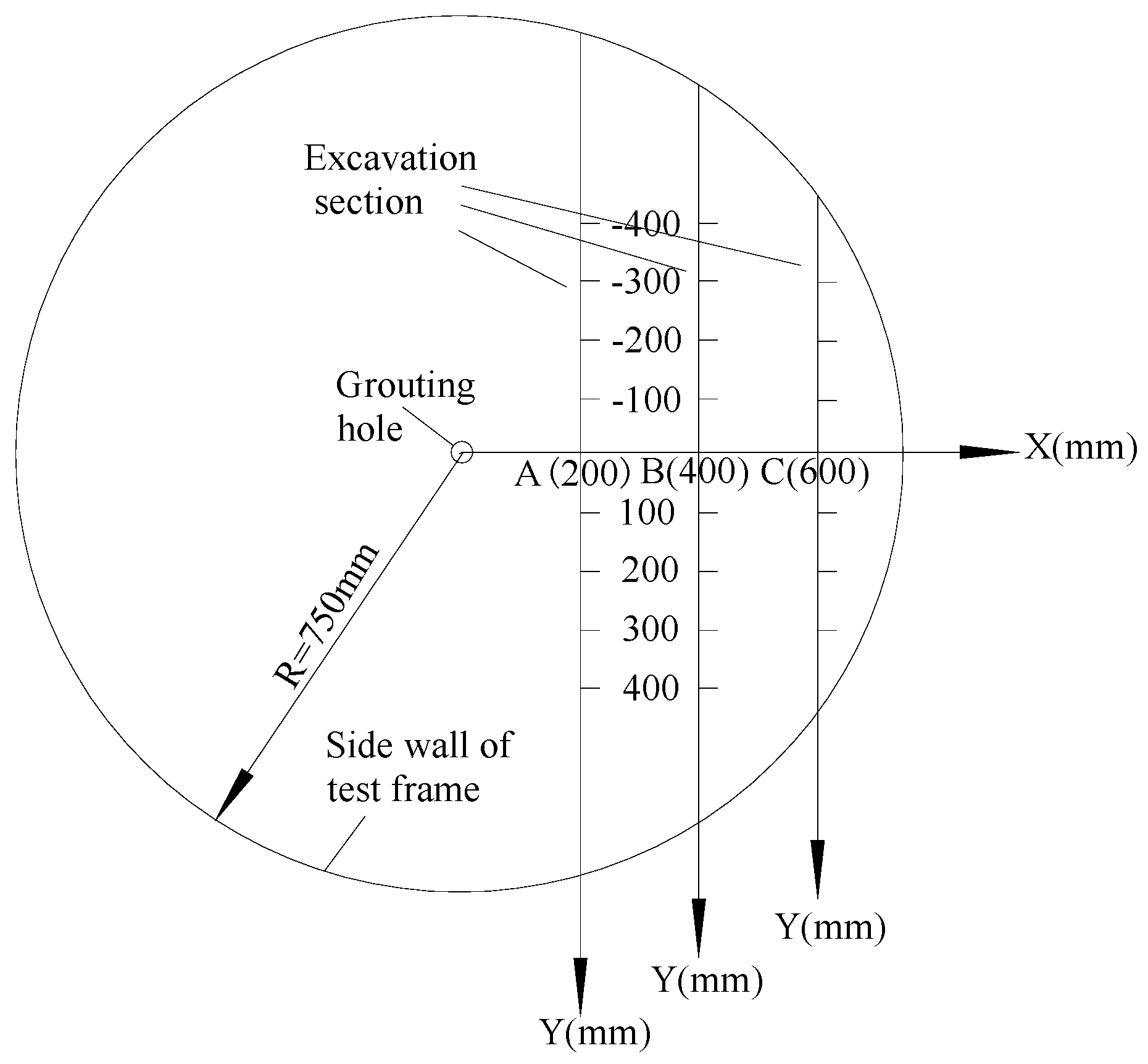
Figure 4 shows the location of excavation section in the simulated test, and the excavation sections were A, B and C, respectively.
As shown in Figure 4, the excavation sections were perpendicular to the bottom plate of the simulated test frame, and they were excavated from the simulated test frame to the grouting hole. The line that crossed the grouting hole and that was perpendicular to the excavation section was taken as the x-axis. The intersection line between the excavation section and the floor of the simulated test rack was taken as the y-axis. In the excavation process, the section excavation method was adopted. The excavation step length was 200 mm, and the excavation plane was smooth. The position coordinates of the grouting veins and thickness variation of the grouting veins were recorded in detail.
Figure 5 presents the veins of the whole excavation section of the three segmental grouting works.
With respect to the grouting vein that was exposed by the excavation, it was found that when the segmented split grouting was compared with the traditional full grouting, the segmented split grouting had a complex network of veins in the soft filling medium, and the spatial distribution of the veins was significantly different. Moreover, based on the thickness distribution and the morphological characteristics of the grouting veins, it could be divided into skeleton veins, cross-grid grouting veins, and parallel dispersed grouting veins.
4.1.1. Skeleton Vein
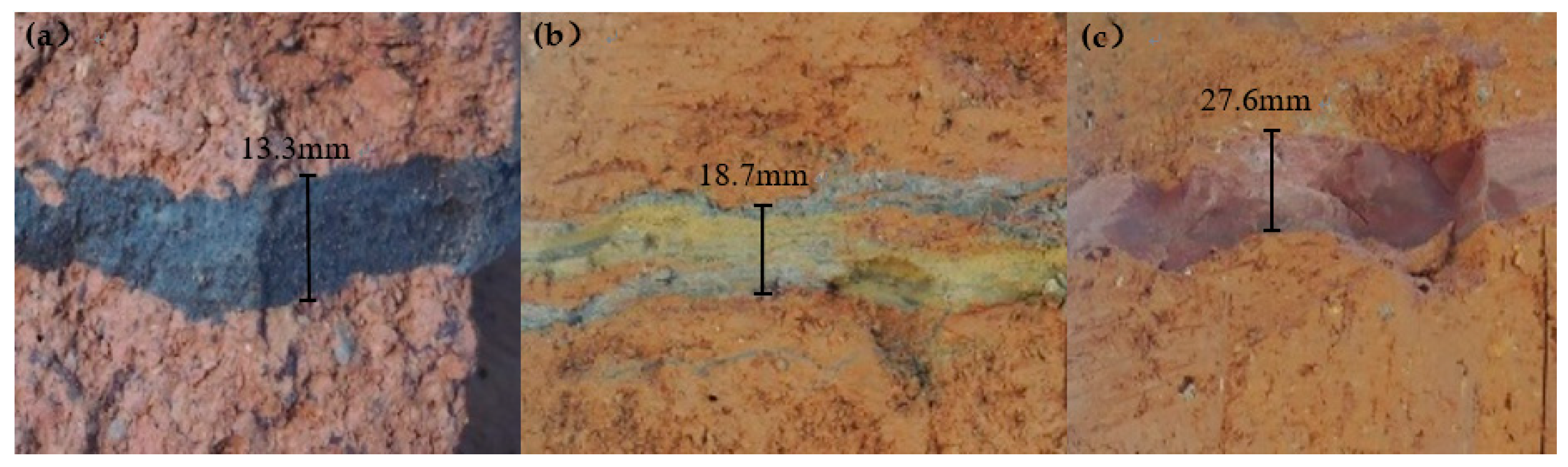
Figure 6 presents the skeleton veins of the three segmental grouting work. Figure 6a–c present the original skeleton vein in the first segmental grouting work, the yellow grouting vein in the second segmental grouting work, and the red grouting vein in the third segmental grouting work.
Considering the grouting hole as the origin, the skeleton vein extended outward along the direction of grout migration. Moreover, the thickness of the grouting vein was larger near the grouting hole. From the excavation results, it was found that the thickness of the grouting veins of each segmental grouting work was different along the grouting pipe. The thickness of the grouting veins was larger near the grouting hole, and the injected medium compressed by the grouting vein was denser. This indicated that the supporting role of the skeleton vein was more significant when the grouting vein was closer to the location of the grouting hole.
Figure 7 presents the thickness distribution of the skeleton veins in the A (200 mm) section. Figure 7a presents the thickness distribution of the skeleton veins along the direction of grout migration. Figure 7b presents the thickness distribution proportions of the different skeleton veins.
As presented in Figure 7, the skeleton veins were mainly distributed near the A (200 mm) section, and the thicknesses of the skeleton veins were mainly concentrated within the range of 10–20 mm. Moreover, the skeleton veins were close to the overflow hole, and the thicknesses of the skeleton veins decreased significantly along the direction of grout migration.
4.1.2. Cross-Grid Grouting Vein
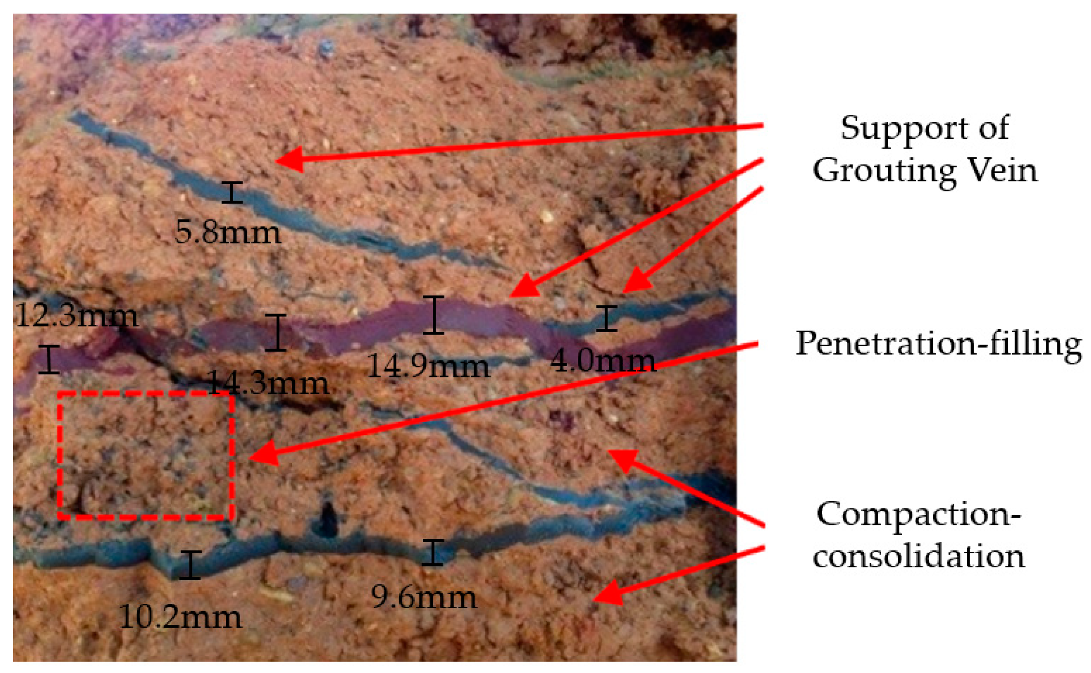
Figure 8 presents the cross-grid grouting veins after the three segmental grouting works.
As presented in Figure 8, the grouting veins of each segmental grouting work intersected each other to form a more distinct cross-grid grouting vein structure. Under the condition of subsection split grouting, the formation stress was the same as the original formation stress in the first segmental grouting work, whereas the formation stress was changed in the residual grouting segments. The change of the formation stress resulted in a change in split direction; thus, the splitting channel developed in a zigzag manner along the direction of grout migration. The grouting veins of each segmental grouting work converged and intersected in the section of the lower formation stress to form cross-grid grouting veins in the region. There were three different reinforcement areas in the area affected by the cross-grid grouting vein, namely, the grouting vein skeleton area, the penetration-filling area, and the compacted area. Therefore, the support of the grouting vein, penetration-filling, and compaction-consolidation were the three main reinforcement modes of the cross-grid grouting vein, and they were synergistic and complementary.
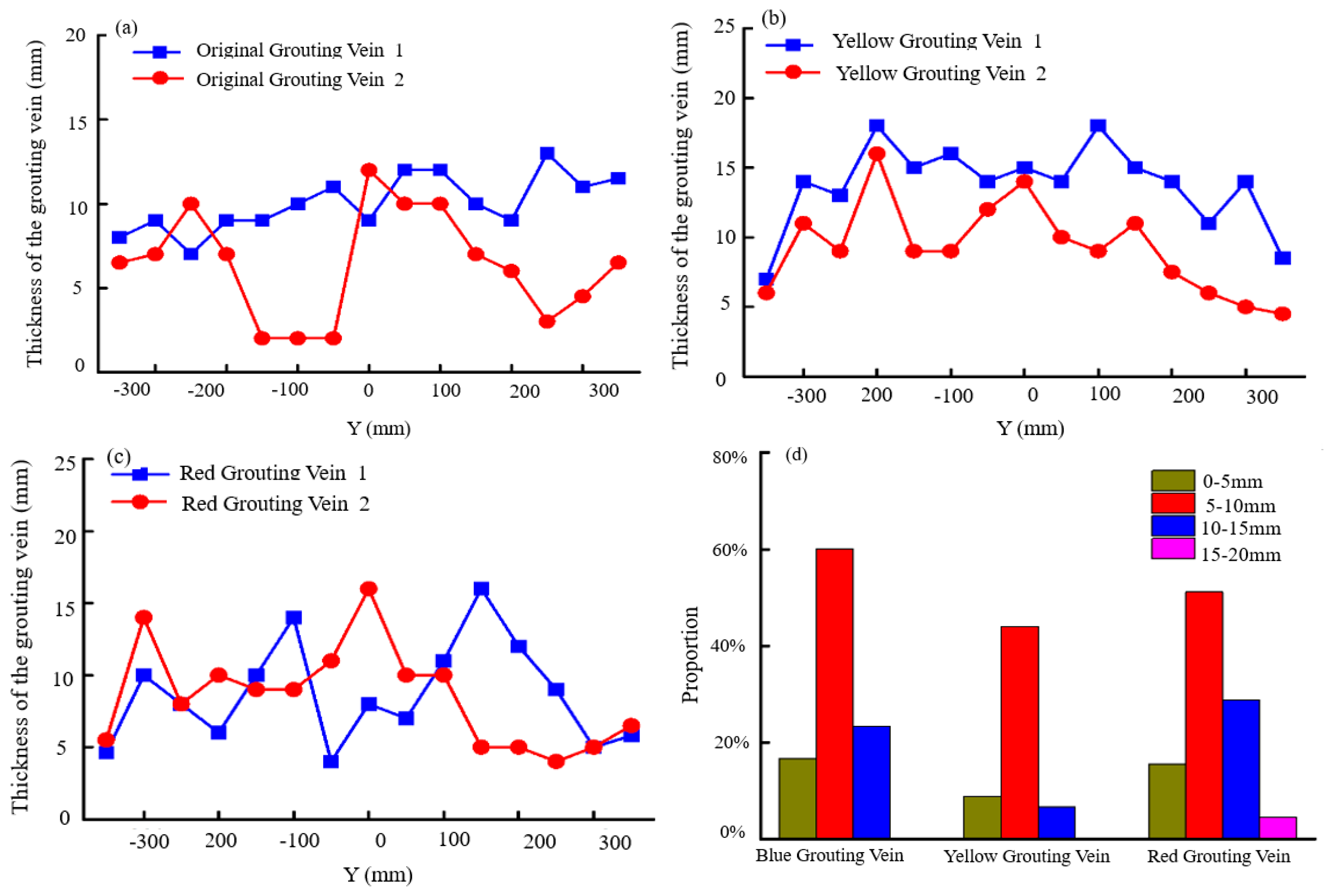
Figure 9 presents the thickness distribution of the grouting veins in the B (400 mm) section. Figure 9a–c present the thickness distribution of the original grouting vein, the yellow grouting vein, and the red grouting vein along the direction of grout migration, respectively. Figure 9d presents the thickness distribution proportions of the different grouting veins.
From the results of the excavation, the cross-grid grouting veins were concentrated near the B (400 mm) section. As presented in Figure 9, it was found that the thicknesses of the grouting veins were within the range of 5–15 mm, and an increase in the distance from the grouting hole resulted in a decrease in the thickness of the grouting veins. Due to the mutual influence of each segmental grouting work, the veins exhibited irregular variations at the local location.
4.1.3. Parallel Dispersed Grouting Vein
Figure 10 presents the parallel dispersed grouting veins. Figure 10a presents the original-red parallel dispersed grouting veins, and Figure 10b presents the blue-yellow parallel dispersed grouting veins.
The parallel dispersed grouting vein was mostly present at a position that was far away from the grouting hole and close to the grout frontal surface. With an increase in the distance of the grout migration from the grouting hole, the grout pressure gradually decreased, resulting in a smaller opening of the split channel. The grouting veins of this type were approximately parallel. There were many permeable diffusion regions near the parallel dispersed grouting vein. In the region that was affected by the parallel dispersed grouting vein, the reinforcement modes were the same as that of the cross-grid grouting vein, including the support of the grouting vein, penetration-filling, and compaction-consolidation. Compared with the skeleton vein and the cross-grid grouting vein, the thicknesses of most of the parallel dispersed grouting veins were relatively small, and the reinforcement effect of the grouting veins was significantly limited to the injected medium.
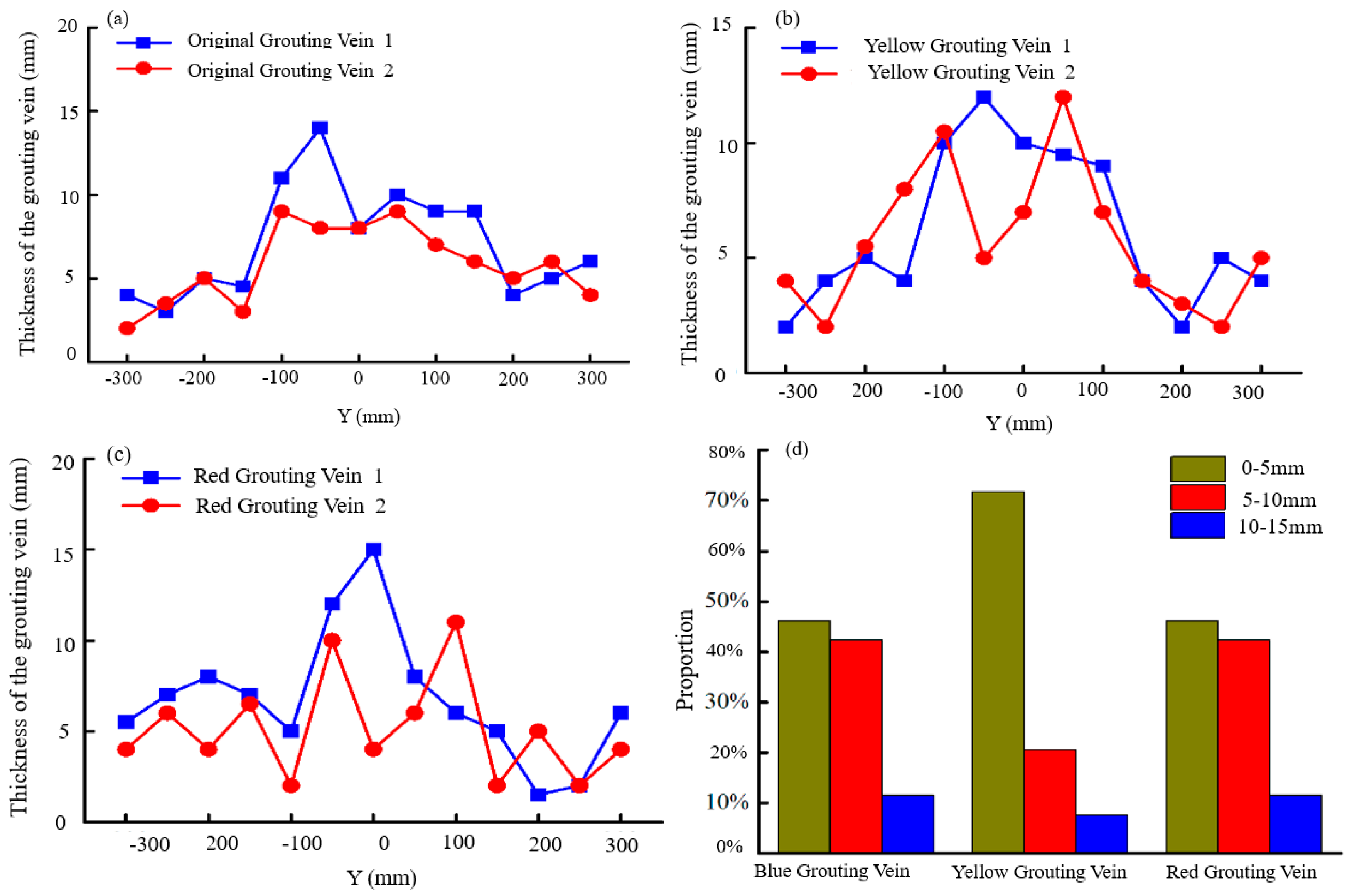
Figure 11 presents the thickness distribution of the grouting veins in the C (600 mm) section. Figure 11a–c presents the thickness distributions of the original grouting vein, the yellow grouting vein, and the red grouting vein along the direction of grout migration, respectively. Figure 10d presents the thickness distribution proportions of the different grouting veins.
From the results of the excavation, more parallel grouting veins were mainly distributed near the C (600 mm) section. As presented in Figure 11, it was found that the thicknesses of the parallel grouting veins were concentrated to within a range of 0–10 mm. The grouting veins were distributed near the grout frontal surface, and a decrease in the grouting vein thickness was clearly observed.
Therefore, when the soft filling medium was reinforced by segmented grouting, skeleton grouting veins, cross-grid grouting veins, and parallel dispersed grouting veins were formed in an orderly manner, in accordance with the increase in the distance from the grouting hole. The reinforcement modes of the subsection split grouting were the main supports of the grouting vein skeleton, permeation-filling, and compaction consolidation.
The thicknesses of the grouting veins in the grouting area decreased with an increase in the distance from the grouting hole. For example, the thicknesses of the skeleton grouting veins were in the range of 10–20 mm, whereas the thicknesses for the parallel grouting veins were in the range of 0–10 mm. The number of grouting veins increased from the grouting hole to the grout frontal surface, and the strikes of the grouting veins exhibited increased randomness.
4.2. Analysis of Grouting Reinforcement Effect
From the results of the distribution characteristics of the grouting veins, the reinforcement effect of the soft filling medium by the split grouting was mainly reflected by two phenomena. On the one hand, the soft filling medium at the corresponding position was replaced by the grouting vein skeleton, which could act as a support for the injected medium. On the other hand, the grouting vein skeleton had a significant compaction-consolidation effect and a permeation-filling effect on the soft filling medium. After the permeation-filling and the compaction-consolidation of the grouting veins, the mechanical properties and the impermeability of the soft filling medium were significantly improved.
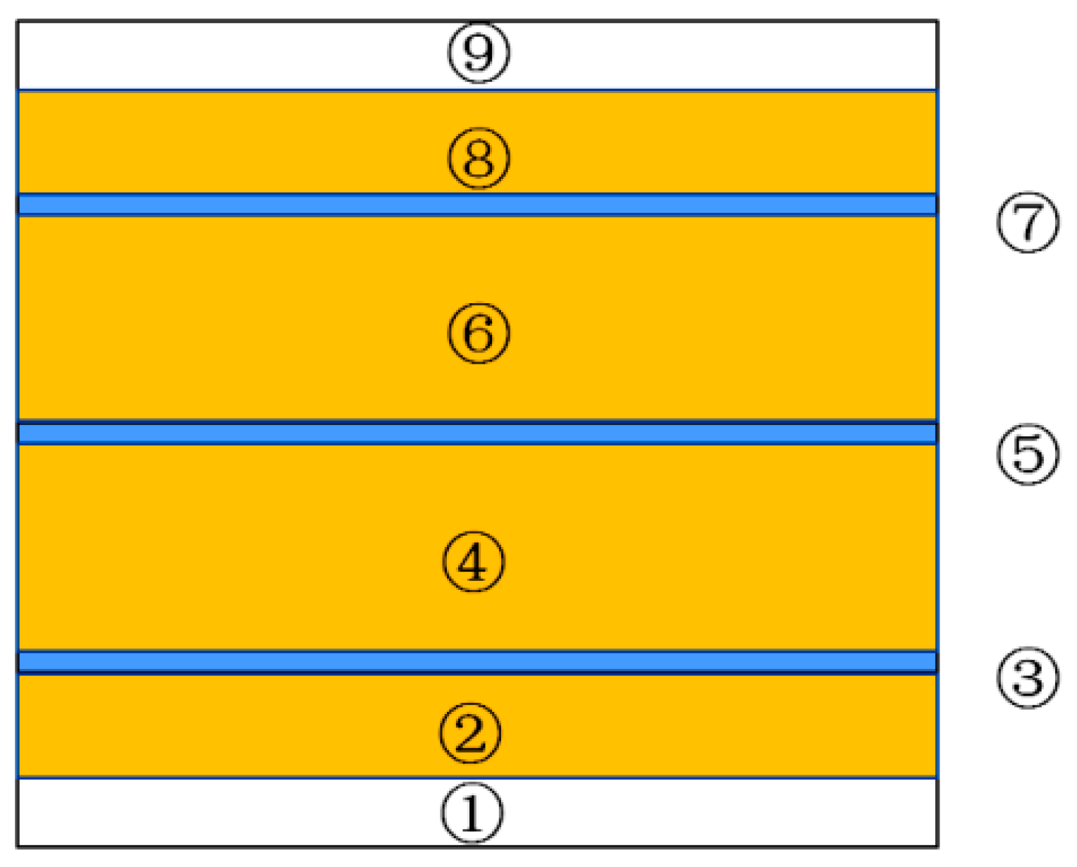
To quantitatively analyze the reinforcement effect, and to determine the quantitative relationship between the mechanical properties and the permeability before and after grouting, the grouting reinforcement area was divided, based on the spatial distribution positions and the reinforcement methods of the grouting veins. It could be divided into three regions: the replacement region of the grouting veins, the grouting split zones, and the grouting compaction zone. The replacement region of the grouting veins was the grouting vein skeleton area; the grouting split zone was the area that was significantly affected by permeation-filling and compaction-consolidation; and the grouting compaction zone was the edge of the influence area of the segmental grouting area, which was dominated by compaction.
Figure 12 presents the schematic diagram of the injected medium zoning. As presented in Figure 12, ① and ⑨ indicate the compact area; ③, ⑤, and ⑦ indicate the replacement region of grouting vein; and ②, ④, ⑥, and ⑧ indicate the grouting split zone formed by the slurry split.
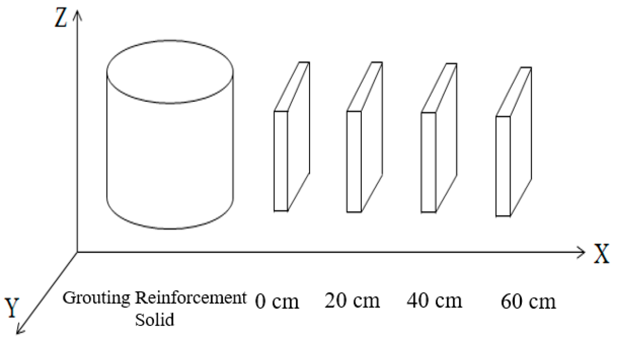
As presented in Figure 13, the cross-section samples of the typical grouting reinforcement area (non-grouting vein replacement area) were selected along the direction of grout diffusion, and the space of each sample was a distance of 20 cm.
4.2.1. Compression Strength
Figure 14 and Figure 15 present the cross section sampling and single cycle compression test in the grouting reinforcement area, respectively.
An electric rotary coring machine was used to sample the grouting reinforcement solid area. The 144 samples were selected, and the diameter and height of the sample were 50 mm and 100 mm, respectively. The compressive strength of the sample was tested according to GB/T 50081-2002, and the elastic modulus of the sample was calculated from the compression stress-strain curve.
The replacement region of the grouting veins was mainly filled with grout stone; therefore, the elastic modulus (14 days) of the grout stone was used as the elastic modulus of the replacement region of the grouting veins. The elastic modulus and the standard deviations of other regions are presented in Table 4.
In Figure 12, the area weighting coefficients of areas ①–⑨ were calculated from the partition characteristics of the injected media, and the equivalent elastic modulus of the grouting reinforcement solid area could then be calculated using the method of the weighted mean value.
The average elastic modulus of a grouting reinforcement area was calculated by the equation [24] as follows:
where j is the section number ranging from 1–4, which represents the sections corresponding to x = 60 cm, x = 40 cm, x = 20 cm, and x = 0 cm, respectively; i is the area number of the section, which ranges from 1–9; m is the sample number in a certain area, which ranges from 1–6; Ej−i is the average elastic modulus of the excavation section j and area i; and Ej−i−m is the average elastic modulus of the excavation section j, area i, and sample m.
The average elastic modulus of a section can be expressed by the equation [24] as follows:
where Sj is the total section area of the excavation section j; Sj−i is the total section area of the excavation section j and area i; and Ej is the average elastic modulus of the excavation section j.
The equivalent elastic modulus of the grouting reinforcement solid is:
where Ee is the equivalent elastic modulus of the grouting reinforcement solid.
According to the calculation Formula (1)–(3) and the elastic modulus data in Table 4, the equivalent elastic modulus of the grouting reinforcement solid Ee was 205.2 MPa. Before the split grouting, the elastic modulus ES of the soft filling medium sample without grouting was 2 MPa. Thus:
Under the experimental conditions used in this study, the elastic modulus of the grouting reinforcement solid increased on average by a factor greater than 100 after the grouting reinforcement, thus indicating that the support of the grouting vein, permeation-filling, and the compaction-consolidation formed by the split grouting could significantly improve the mechanical properties of the injected medium. Segmental split grouting was therefore effective in improving the mechanical properties of the weak filling media.
4.2.2. Anti-Permeability
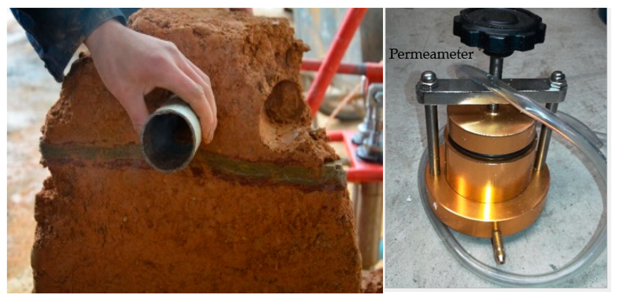
Figure 16 presents the specimen sampling of the grouting reinforcement solid area and the permeability test. The permeability coefficient of the sample was tested using a TST-55 permeameter, and the diameter and height of the sample were 61.8 mm and 40 mm, respectively. The sampling distance of each reinforced area was 30 cm.
As shown in the Table 5, the permeability coefficients of each section were calculated using Darcy’s law. The permeability coefficient of the grouting reinforcement solid was measured separately, and was 5.5 × 10⁻⁸ cm/s.
Figure 17 presents the schematic diagram of the stratified seepage in the parallel and vertical grouting vein directions.
As presented in Figure 17, the soft filling medium exhibited significant stratification characteristics after grouting. The grouting reinforcement solid area was composed of lamellar regions with different permeability coefficients. According to the principle of seepage mechanics, the equivalent permeability coefficient in the parallel grouting vein direction was calculated by the equation [25] as follows:
where Kh is the equivalent permeability coefficient in the parallel grouting vein direction; Hi is the thickness of region i; H is the total thickness of the injected medium; Ki is the average permeability coefficient of region i.
The equivalent permeability coefficient in the vertical grouting vein direction was calculated by the equation [25] as follows:
where Kh is the equivalent permeability coefficient in the vertical grouting vein direction.
The permeability coefficient of the C-GT grouting reinforcement solid was small, thus Kh >> Kv. The equivalent permeability coefficient Kh, which was most unfavorable in the parallel slurry direction, was calculated to represent the permeability coefficient of the grouting reinforcement solid. According the permeability coefficient of the soft filling medium in Table 5, the permeability coefficient of the grouting vein, and formula (5), the equivalent permeability coefficient of the grouting reinforcement solid Kh was calculated as 12.95 × 10⁻⁶ cm/s, whereas the initial permeability coefficient of the soft filling medium KS was 5.2 × 10⁻⁴ cm/s. Therefore:
After grouting, the permeability coefficient was the biggest in the parallel grouting direction, but the permeability coefficient of the soft filling medium was reduced by a factor greater than 40. This indicated that the compaction effect of the grouting vein formed by the split grouting reduced the permeability of the soft filling medium. Thus, the subsection split grouting could effectively improve the anti-seepage performance of the soft filling medium.
5. Conclusions
Segmental splitting grouting is widely used in soft ground grouting reinforcement projects, such as fault fracture zones and the quaternary topsoil layers. The study of the section splitting grouting mechanism is helpful to realize the quantification of grouting design. The simulation test formed the following important conclusions:
- (1)
- A three-dimensional grouting simulation test system was developed, which could realize the subsection split grouting in a soft filling medium. Moreover, it could be used to conduct the excavation observation and sampling analysis after grouting.
- (2)
- There was no permeable grouting in the soft filling medium with poor permeability, but the form of grouting in this medium was mainly split grouting. Three types of veins were formed when the soft filling medium was consolidated by subsection split grouting; namely, skeleton support veins, cross-grid pulp veins, and parallel dispersed pulp veins. The thicknesses of the grouting veins decreased gradually as the distance from the grouting holes increased, and the strikes of grouting veins exhibited increased randomness.
- (3)
- The special grouting reinforcement mechanism under the section split grouting was determined, and it consisted mainly of the reinforcement mode of the grout vein skeleton support, permeation-filling, and compaction-consolidation.
- (4)
- The elastic modulus of the grouting reinforcement solid increased on average by a factor greater than 100, and the permeability coefficient decreased on average by a factor greater than 40 in the direction of the parallel grouting vein with the most impermeable solid. This confirmed that segmental split grouting is an effective method for the improvement of the mechanical properties and the impermeability of the weak filling media.
The soil used is sourced from the F2 fault of Yonglian Tunnel in Jilian Expressway, Jiangxi Province, China in this paper. The test results obtained are aimed at the injected medium that is used in this experiment. It is not clear whether the test results are applicable to other media. A plan has been drawn up to conduct experimental research in this field.
Author Contributions
Z.L., S.L. and Q.Z. conceived of and designed the study. Z.L. and Q.Z. developed the three-dimensional grouting simulation test system. Z.L., H.L. and Y.L. performed the experiments. Z.L., S.L., Q.Z., H.L. and Y.L. wrote and modified the paper.
Funding
This work was supported by the National Key Research and Development Project (grant number 2016YFC0801604), and the National Natural Science Foundation of China (grant number 51779133).
Conflicts of Interest
The authors declare no conflict of interest.
References
- Marchi, M.; Gottardi, G.; Soga, A.K. Fracturing Pressure in Clay. J. Geotech. Geoenviron. Eng. 2014, 140, 04013008. [Google Scholar] [CrossRef]
- Bezuijen, A.; te Grotenhuis, R.; van Tol, A.F.; Bosch, J.W.; Haasnoot, J.K. Analytical Model for Fracture Grouting in Sand. J. Geotech. Geoenviron. Eng. 2011, 137, 611–620. [Google Scholar] [CrossRef]
- Hernqvist, L.; Gustafson, G.; Fransson, Å.; Norberg, T. A statistical grouting decision method based on water pressure tests for the tunnel construction stage—A case study. Tunn. Undergr. Space Technol. 2013, 33, 54–62. [Google Scholar]
- Tan, Y.H. Evolutionary Mechanism of Mud Bursting through Water-Inrich Fault in Tunnels and Engineering Applications. Ph.D. Thesis, Shan Dong University, Jinan, China, 2017. (In Chinese). [Google Scholar]
- Yu, W.S. Grouting Diffusion Mechanism in Mud Filled Fault Fracture Zone of Tunnel and It’s Engineering Application. Ph.D. Thesis, Changsha University of Science & Technology, Changsha, China, 2017. (In Chinese). [Google Scholar]
- Wang, Z.C.; Li, F.Q. Slurry water curtain grouting and its mechanism in complex coal mine area. J. Cent. South Univ. (Sci. Technol.) 2013, 44, 778–784. (In Chinese) [Google Scholar]
- Zhou, K.F.; Li, Y.Z. Influence of grouting on the mechanical characteristic of stratified rock slope. J. Cent. South Univ. (Sci. Technol.) 2012, 43, 724–729. (In Chinese) [Google Scholar]
- Zhang, M.; Zou, J.; Chen, J.; Li, X.; Li, Z. Analysis of soil fracturing grouting pressure under asymmetric loads. Rock Soil Mech. 2013, 34, 2255–2263. (In Chinese) [Google Scholar]
- Li, S.C.; Zhang, W.J.; Zhang, Q.; Zhang, X.; Liu, R.; Pan, G.; Li, Z.; Chen, Z. Research on advantage-fracture grouting mechanism and controlled grouting method in water-rich fault zone. Rock Soil Mech. 2014, 3, 745–751. (In Chinese) [Google Scholar]
- Sun, F.; Chen, T.; Zhang, D.; Zhang, Z.; Li, P. Study on fracture grouting mechanism in subsea tunnel based on Bingham fluids. J. Beijing Jiaotong Univ. 2009, 33, 1–6. (In Chinese) [Google Scholar]
- Zhang, Z.; Zou, J. Penetration radius and grouting pressure in fracture grouting. Chin. J. Geotech. Eng. 2008, 30, 181–184. (In Chinese) [Google Scholar]
- Sun, F.; Zhang, D.; Chen, T. Fracture grouting mechanism in tunnels based on time-dependent behaviors of grout. Chin. J. Geotech. Eng. 2011, 33, 88–93. (In Chinese) [Google Scholar]
- Zhang, Q.; Zhang, L.; Liu, R.; Yu, W.; Zheng, Z.; Wang, H.; Zhu, G. Split grouting theory based on slurry-soil coupling effects. Chin. J. Geotech. Eng. 2016, 38, 323–330. (In Chinese) [Google Scholar]
- Zhang, L. Study on Penetration and Reinforcement Mechanism of Grouting in Sand Layer Disclosed by Subway Tunnel and Its Application. Ph.D. Thesis, Shandong University, Jinan, China, 2017. (In Chinese). [Google Scholar]
- Li, P.; Zhang, X.; Zhang, Q. Analysis on three-dimensional diffusion mechanism of multi-sequence grouting in fault. Geotech. Spec. Publ. 2016, 2016, 121–129. (In Chinese) [Google Scholar]
- Li, P.; Zhang, Q.; Zhang, X. Grouting diffusion characteristics in faults considering the interaction of multi-sequence grouting. Int. J. Geomech. 2016, 17, 04014117. (In Chinese) [Google Scholar]
- Zhang, B.W. Experimental Study on Compaction Grouting and Fracture Grouting of Soft Clay in the High-Speed Rail Way Foundation. Ph.D. Thesis, Southwest Jiaotong University, Chengdu, China, 2013. (In Chinese). [Google Scholar]
- Zheng, C.C. Estimation on Penetrating Radius of Stable Cement Grouts in Rock Fractures. J. Water Resour. Arch. Eng. 2006, 4, 1–5. (In Chinese) [Google Scholar]
- Li, P.; Zhang, Q.S.; Zhang, X.; Li, S.; Zhang, W.; Li, M.; Wang, Q. Analysis of fracture grouting mechanism based on model test. Chin. J. Rock Mech. Eng. 2014, 35, 3221–3230. (In Chinese) [Google Scholar]
- Darling, W.G.; Bath, A.H.A. Stable isotope study of recharge processes in the English Chalk. J. Hydrol. 1988, 101, 31–46. [Google Scholar] [CrossRef]
- Li, Z. Mechanism of Grouting Spread and Reinforcement on Soft Medium in Fault and Its Application. Ph.D. Thesis, Shan Dong University, Jinan, China, 2015. (In Chinese). [Google Scholar]
- Liu, R.; Li, S.; Zhang, Q.; Yuan, X.; Han, W. Experiment and application research on a new type of dynamic water grouting material. Chin. J. Rock Mech. Eng. 2011, 30, 1454–1459. (In Chinese) [Google Scholar]
- Sha, F.; Liu, R.; Li, S.; Lin, C.; Li, Z.; Liu, B.; Bai, J. Application on different types of cementitious grouts for water-leakage operational tunnels. J. Cent. South Univ. (Sci. Technol.) 2016, 47, 4163–4172. (In Chinese) [Google Scholar]
- Xu, Z.L. Elasticity; Higher Education Press: Beijing, China, 2013. (In Chinese) [Google Scholar]
- Liu, J.J.; Zhang, B.H. Fluid Mechanic; Peking University Press: Beijing, China, 2016. (In Chinese) [Google Scholar]
Figure 1.
Model test equipment.
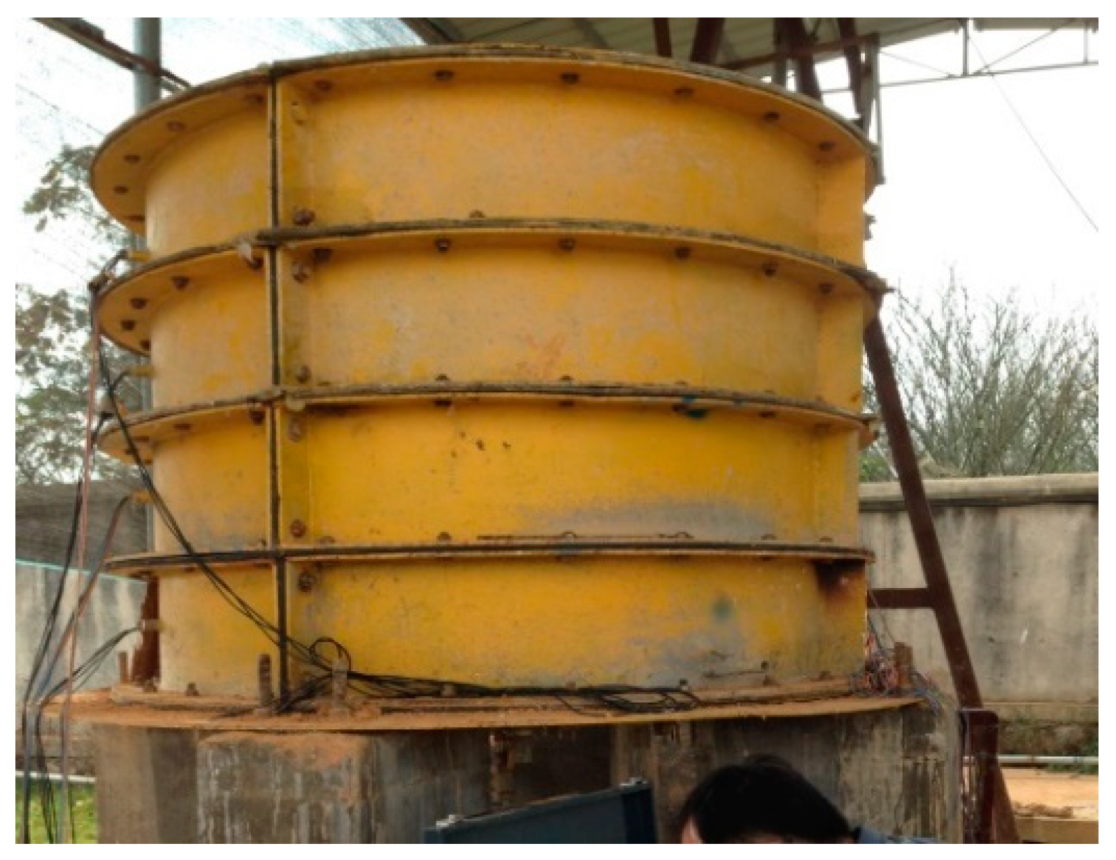
Figure 2.
The internal preset device: (a) the physical picture of the internal preset device, (b) the principle of pressure bearing separator.
Figure 2.
The internal preset device: (a) the physical picture of the internal preset device, (b) the principle of pressure bearing separator.
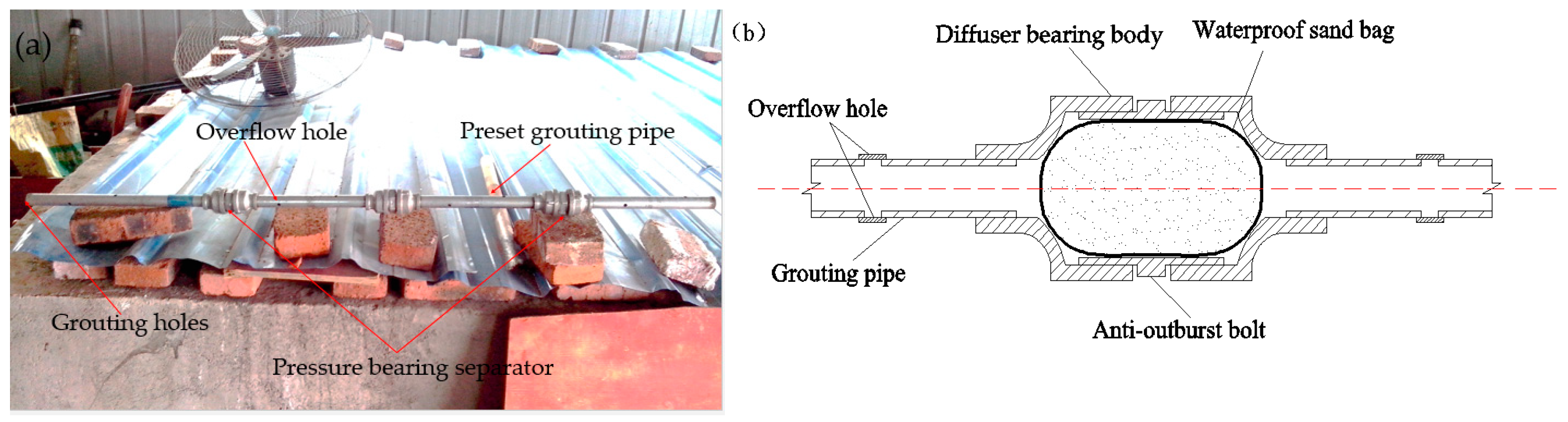
Figure 3.
Internal structure of the simulated test.
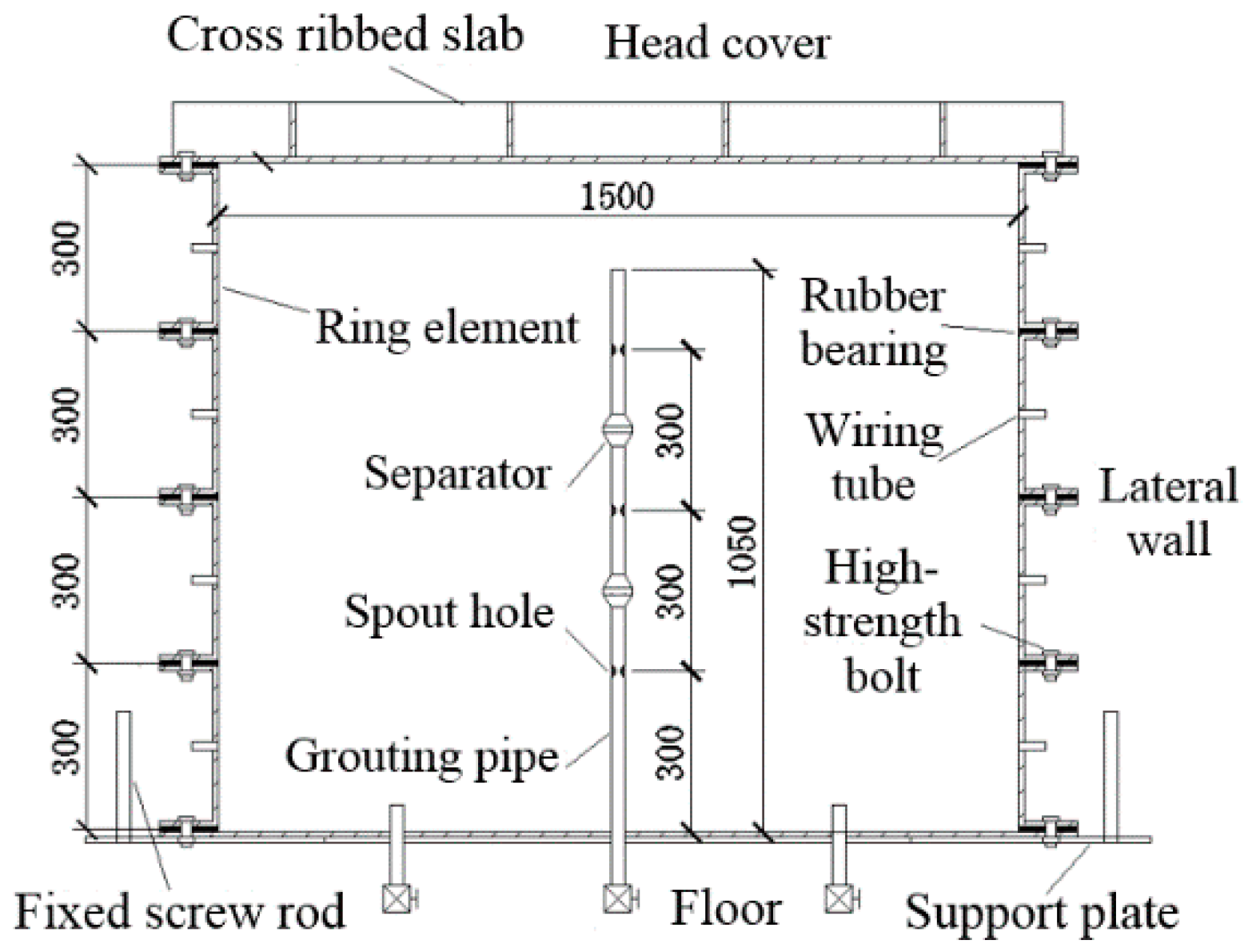
Figure 4.
Location of excavation section.

Figure 5.
The veins of the whole excavation section.
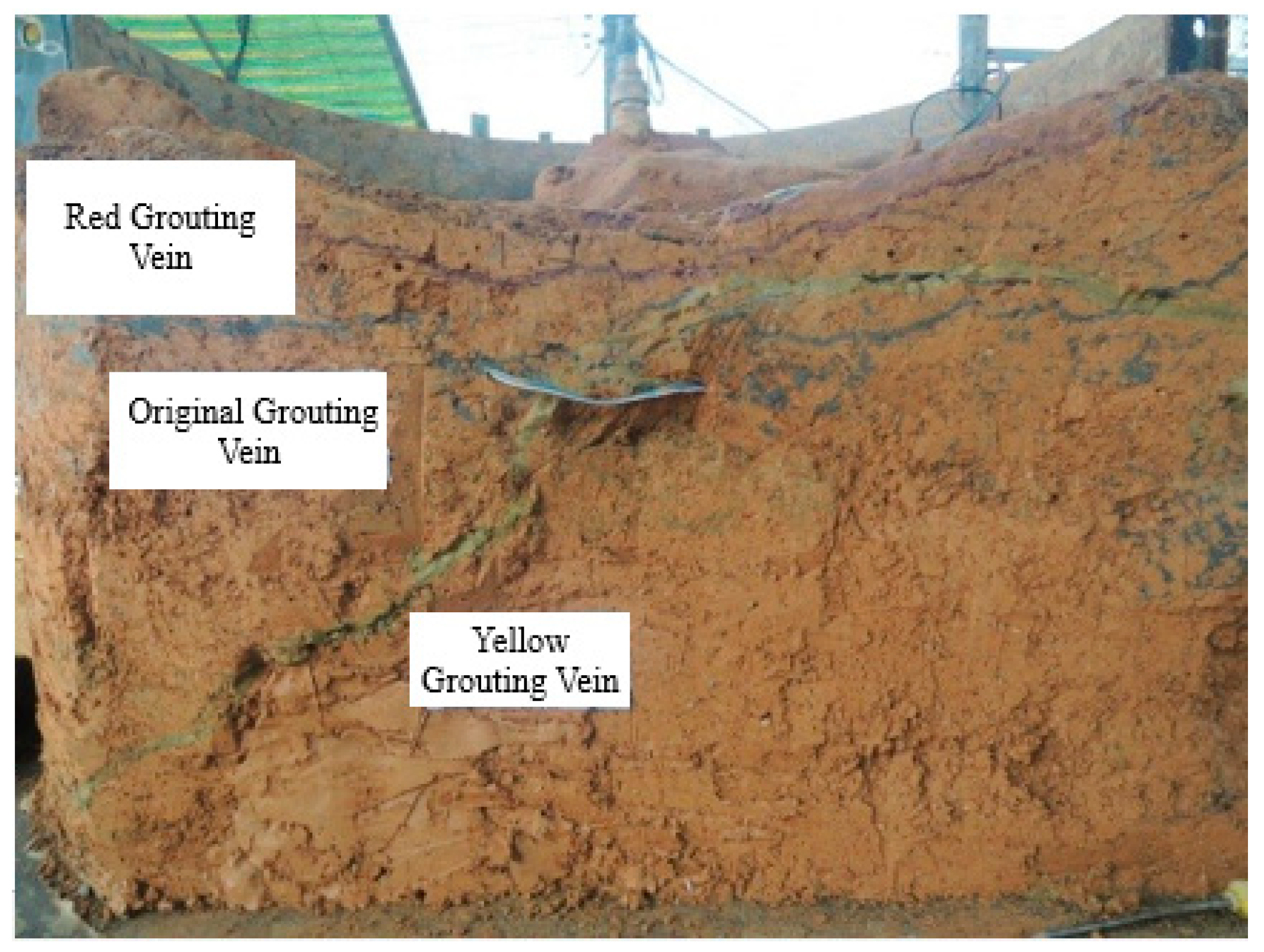
Figure 6.
Framework grouting vein: (a) original grouting vein, (b) yellow grouting vein, and (c) red grouting vein.
Figure 6.
Framework grouting vein: (a) original grouting vein, (b) yellow grouting vein, and (c) red grouting vein.

Figure 7.
Thickness distribution of the grouting veins in A (200 mm) section: (a) thickness distribution of the grouting veins along the direction of grout migration; and (b) thickness distribution proportions of the different grouting veins.
Figure 7.
Thickness distribution of the grouting veins in A (200 mm) section: (a) thickness distribution of the grouting veins along the direction of grout migration; and (b) thickness distribution proportions of the different grouting veins.
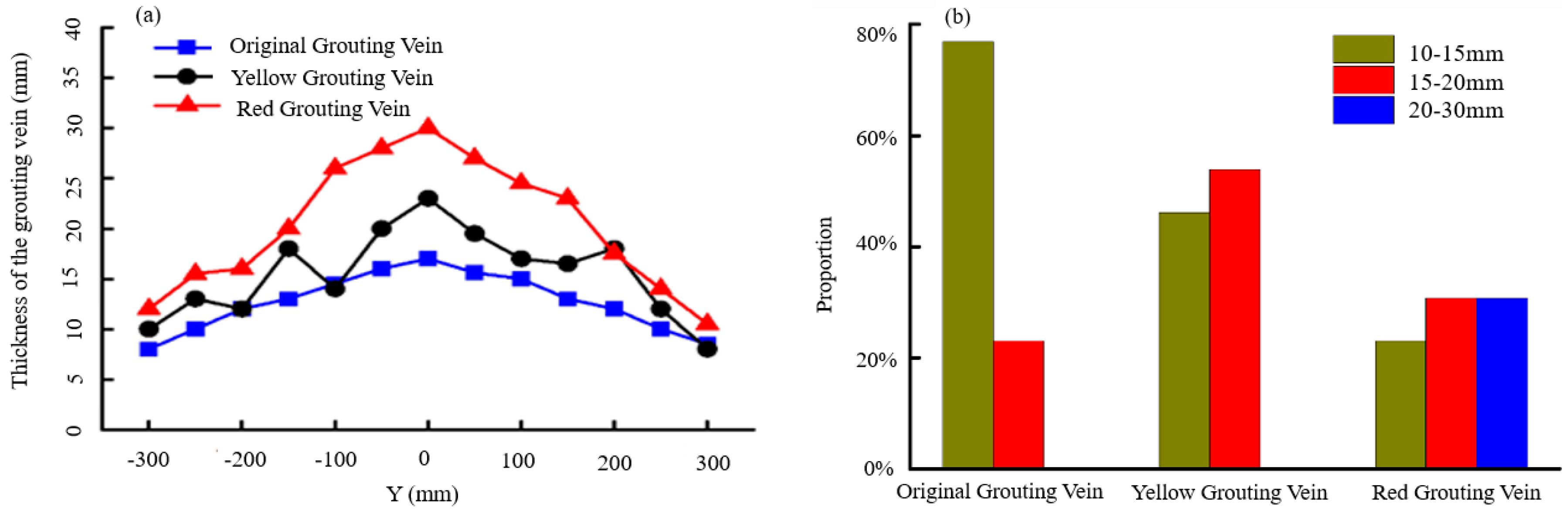
Figure 8.
Cross-grid grouting vein.

Figure 9.
Thickness distribution of the grouting veins in the B (400 mm) section: (a) thickness distribution of the original grouting vein; (b) thickness distribution of the yellow grouting vein; (c) thickness distribution of the red grouting vein; and (d) thickness distribution proportions of the different grouting veins.

Figure 10.
Parallel dispersed grouting veins: (a) original-red parallel dispersed grouting veins and (b) blue-yellow parallel dispersed grouting veins.
Figure 10.
Parallel dispersed grouting veins: (a) original-red parallel dispersed grouting veins and (b) blue-yellow parallel dispersed grouting veins.
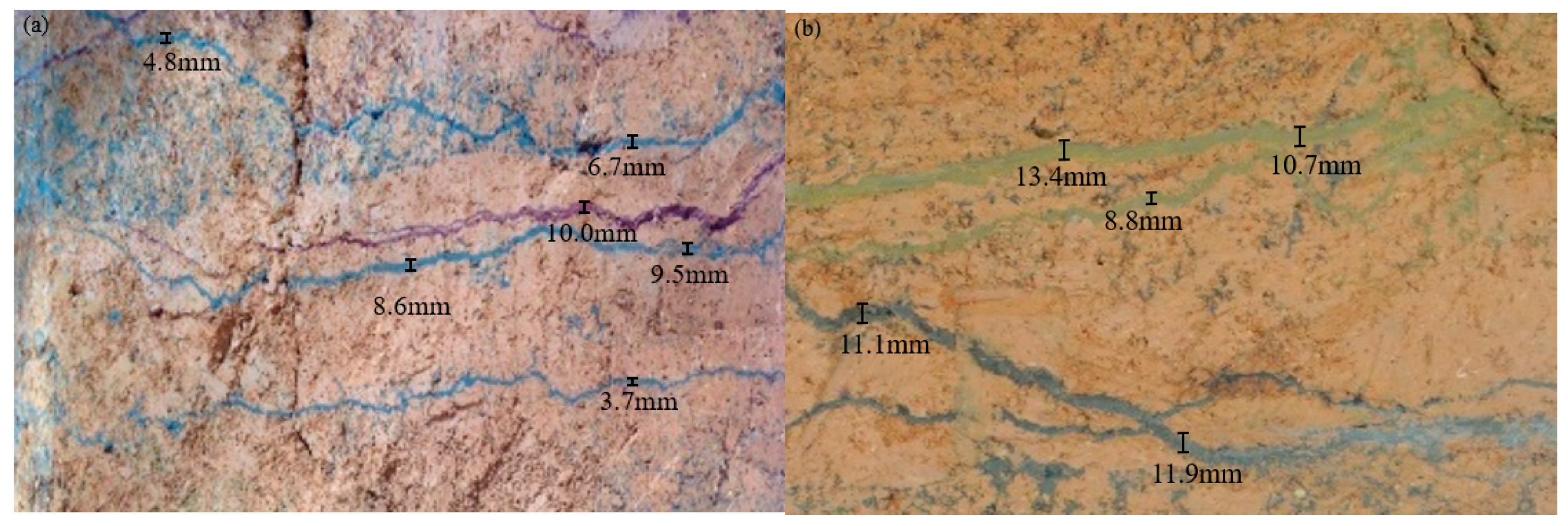
Figure 11.
Thickness distribution of the grouting veins in the C (600 mm) section: (a) thickness distribution of the original grouting veins; (b) thickness distribution of the original grouting veins; (c) thickness distribution of the red grouting veins; (d) thickness distribution proportions of the different grouting veins.

Figure 12.
Schematic diagram of the injected medium zoning.

Figure 13.
Location of cross-section sampling.

Figure 14.
Cross section sampling.
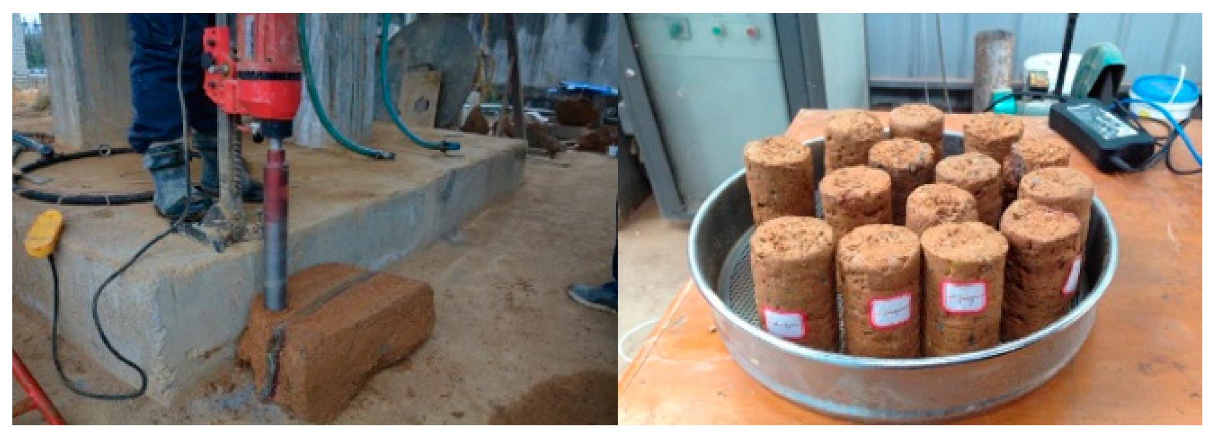
Figure 15.
Compression test.

Figure 16.
Specimen sampling and permeability test.

Figure 17.
Schematic diagram of stratified seepage: (a) parallel grouting vein direction and (b) vertical grouting vein direction.
Figure 17.
Schematic diagram of stratified seepage: (a) parallel grouting vein direction and (b) vertical grouting vein direction.


Table 1.
Basic physical parameters of the soil [21].
Table 1.
Basic physical parameters of the soil [21].
| Initial Water Content | Dry Density | Permeability Coefficient | Liquid Limit | Fine Cement | Porosity | |
|---|---|---|---|---|---|---|
| Material type | ω (%) | ρd (g·cm−1) | k (cm·s−1) | WI (%) | M (%) | P (%) |
| Soft clay | 37.8 | 1.17 | 5.2 × 10⁻⁴ | 45.9 | 36.7 | 31.5 |
Table 2.
Parameters of the C-GT slurry.
| W/C | VC:VGT | Stone Rate (%) | Gel Time (s) | Age Strength (MPa) | ||||||
|---|---|---|---|---|---|---|---|---|---|---|
| Initial Setting Time | Final Setting Time | 1 h | 5 h | 1 Day | 3 Days | 14 Days | 28 Days | |||
| 1:1 | 1:1 | 85 | 45 | 80 | 0.5 | 1.8 | 3.0 | 7.0 | 8.0 | 8.9 |
Table 3.
Selection of grouting parameters.
| Serial Number | Order | Design Grouting Rate | Design Grouting Pressure (MPa) | Slurry Color | Bottom Height of Overflow Hole (cm) |
|---|---|---|---|---|---|
| 1 | First | 0–5 L/min | 1 | original | 30 |
| 2 | Second | 0–5 L/min | 1 | yellow | 60 |
| 3 | Third | 0–5 L/min | 1 | red | 90 |
Table 4.
Data sheet of the specimens in the splitting and compacting zone.
| Elastic Modulus(E)/MPa and Standard Deviations(S) | ||||||||||||
|---|---|---|---|---|---|---|---|---|---|---|---|---|
| Location of Sample Cross-Section (cm) | Compacting Zone 1 | Splitting Zone 2 | Splitting Zone 4 | Splitting Zone 6 | Splitting Zone 8 | Compacting Zone 9 | ||||||
| E | S | E | S | E | S | E | S | E | S | E | S | |
| x = 0 | 96 | 1.56 | 182 | 1.45 | 284 | 2.23 | 235 | 2.21 | 168 | 1.10 | 94 | 3.21 |
| 124 | 1.36 | 205 | 2.11 | 296 | 3.12 | 312 | 5.36 | 212 | 3.65 | 126 | 2.10 | |
| 178 | 1.23 | 285 | 4.21 | 340 | 4.96 | 325 | 4.25 | 271 | 4.23 | 182 | 0.86 | |
| 152 | 2.65 | 247 | 3.95 | 388 | 6.02 | 363 | 6.21 | 243 | 5.21 | 148 | 0.79 | |
| 110 | 3.21 | 226 | 4.23 | 312 | 2.70 | 318 | 3.65 | 184 | 1.89 | 120 | 1.89 | |
| 85 | 2.21 | 196 | 1.87 | 275 | 1.14 | 304 | 1.58 | 150 | 5.11 | 87 | 2.36 | |
| x = 20 | 80 | 1.26 | 127 | 4.56 | 226 | 3.21 | 185 | 3.65 | 106 | 2.68 | 82 | 0.68 |
| 104 | 1.03 | 196 | 2.36 | 288 | 4.05 | 302 | 5.65 | 172 | 2.13 | 94 | 1.65 | |
| 148 | 2.01 | 264 | 3.29 | 307 | 3.04 | 325 | 4.96 | 203 | 0.98 | 138 | 2.31 | |
| 94 | 0.98 | 225 | 1.95 | 334 | 5.69 | 296 | 3.68 | 245 | 3.69 | 124 | 1.15 | |
| 87 | 1.68 | 158 | 0.98 | 272 | 4.12 | 252 | 1.56 | 164 | 5.45 | 91 | 2.35 | |
| 74 | 0.45 | 135 | 1.14 | 215 | 3.14 | 201 | 1.02 | 124 | 2.12 | 80 | 1.89 | |
| x = 40 | 65 | 0.65 | 105 | 1.68 | 202 | 4.56 | 196 | 3.68 | 94 | 1.56 | 52 | 1.22 |
| 92 | 1.56 | 150 | 1.89 | 243 | 3.68 | 230 | 2.65 | 144 | 1.68 | 68 | 2.36 | |
| 106 | 1.89 | 226 | 2.68 | 271 | 2.68 | 264 | 2.31 | 191 | 3.21 | 93 | 1.10 | |
| 85 | 0.96 | 210 | 3.87 | 238 | 1.59 | 256 | 1.58 | 244 | 2.68 | 102 | 0.65 | |
| 72 | 1.45 | 154 | 1.56 | 222 | 3.68 | 228 | 2.10 | 141 | 1.36 | 74 | 0.98 | |
| 54 | 1.54 | 96 | 1.68 | 195 | 4.65 | 184 | 1.22 | 116 | 1.26 | 65 | 0.48 | |
| x = 60 | 45 | 0.98 | 67 | 0.98 | 93 | 0.65 | 97 | 0.98 | 54 | 0.79 | 52 | 2.56 |
| 57 | 1.32 | 75 | 1.35 | 114 | 1.56 | 110 | 1.65 | 67 | 0.86 | 66 | 5.65 | |
| 93 | 1.89 | 101 | 1.68 | 146 | 1.75 | 158 | 2.65 | 96 | 1.12 | 80 | 2.65 | |
| 86 | 1.68 | 93 | 2.68 | 134 | 2.31 | 146 | 2.31 | 114 | 2.01 | 64 | 3.57 | |
| 78 | 2.12 | 78 | 0.98 | 102 | 1.62 | 112 | 1.12 | 84 | 1.10 | 48 | 2.32 | |
| 64 | 0.97 | 66 | 1.10 | 88 | 1.59 | 103 | 2.02 | 65 | 0.88 | 35 | 0.68 | |
Table 5.
Permeability coefficients.
| Location of Sample Cross-Section (cm) | Permeability Coefficient (10−6 cm/s) | |||||
|---|---|---|---|---|---|---|
| Compacting Zone | Splitting Zone | |||||
| 1 | 9 | 2 | 4 | 6 | 8 | |
| x = 0 | 8.6 | 27.4 | 0.7 | 0.2 | 0.4 | 1.7 |
| 16.3 | 32.6 | 1.6 | 0.4 | 0.6 | 2.2 | |
| 10.7 | 44.8 | 2.2 | 0.6 | 0.8 | 3.4 | |
| x = 20 | 22.5 | 38.5 | 1.2 | 0.4 | 0.8 | 3.4 |
| 27.4 | 45.4 | 2.3 | 0.4 | 0.6 | 4.4 | |
| 38.6 | 56.8 | 3.3 | 0.8 | 1.0 | 5.8 | |
| x = 40 | 48.1 | 67.4 | 4.6 | 0.7 | 0.7 | 5.7 |
| 52.7 | 71.5 | 5.2 | 0.8 | 0.8 | 6.3 | |
| 64.2 | 82.8 | 6.7 | 0.9 | 1.2 | 7.8 | |
| x = 60 | 68.8 | 78.5 | 5.5 | 0.9 | 1.3 | 7.3 |
| 74.5 | 86.2 | 6.6 | 1.12 | 1.4 | 7.9 | |
| 82.4 | 95.6 | 7.8 | 1.4 | 1.8 | 9.1 | |
© 2018 by the authors. Licensee MDPI, Basel, Switzerland. This article is an open access article distributed under the terms and conditions of the Creative Commons Attribution (CC BY) license (http://creativecommons.org/licenses/by/4.0/).
Share and Cite
MDPI and ACS Style
Li, Z.; Li, S.; Liu, H.; Zhang, Q.; Liu, Y. Experimental Study on the Reinforcement Mechanism of Segmented Split Grouting in a Soft Filling Medium. Processes 2018, 6, 131. https://doi.org/10.3390/pr6080131
AMA Style
Li Z, Li S, Liu H, Zhang Q, Liu Y. Experimental Study on the Reinforcement Mechanism of Segmented Split Grouting in a Soft Filling Medium. Processes. 2018; 6(8):131. https://doi.org/10.3390/pr6080131
Chicago/Turabian StyleLi, Zhipeng, Shucai Li, Haojie Liu, Qingsong Zhang, and Yanan Liu. 2018. "Experimental Study on the Reinforcement Mechanism of Segmented Split Grouting in a Soft Filling Medium" Processes 6, no. 8: 131. https://doi.org/10.3390/pr6080131
Note that from the first issue of 2016, this journal uses article numbers instead of page numbers. See further details here.