Effect of Pore Fluid Pressure on the Normal Deformation of a Matched Granite Joint


1
State Key Laboratory of Geomechanics and Geotechnical Engineering, Institute of Rock and Soil Mechanics, Chinese Academy of Sciences, Wuhan 430071, China
2
University of Chinese Academy of Sciences, Beijing 100049, China
3
College of Civil and Transportation Engineering, Hohai University, Nanjing 210098, China
*
Authors to whom correspondence should be addressed.
Processes 2018, 6(8), 107; https://doi.org/10.3390/pr6080107
Submission received: 1 July 2018
/
Revised: 20 July 2018
/
Accepted: 24 July 2018
/
Published: 1 August 2018
(This article belongs to the Special Issue Fluid Flow in Fractured Porous Media)
Abstract
:The influence of pore fluid pressure on the normal deformation behaviors of joints is vital for understanding the interaction between hydraulic and mechanical processes of joints. The effect of pore fluid pressure on the normal deformation of a granite matched joint was investigated by laboratory experiments. Experimental results indicate pore fluid pressure significantly affects the normal deformation of jointed sample, and the relative normal deformation of jointed sample during fluid injection consists of the opening of the joint and the dilation of host rock. The action of pore fluid pressure on the joint follows the Terzaghi’s effective stress law. The normal deformation of the joint can be well quantitated by the generalized exponential model. The relative normal deformation of host rock during fluid injection would have a linear relationship with pore fluid pressure, and if affected by gas is more pronounced than water.
1. Introduction
The normal deformation of joints or fractures is one of the important mechanical behaviors for rock mass, which significantly affects the transport properties of rock mass [1,2,3,4]. The term “joint” is defined as a crack or fracture in rock when there has been little or no transverse displacement [5]. The aperture of joints or fractures depends on the normal stress and on the pore fluid pressure in some engineering [6,7,8,9,10], such as oil or gas exploitation, enhanced geothermal system, and CO2 geological storage, underground disposal of nuclear waste, and so on. The normal deformation behaviors of joints play an important role between hydraulic and mechanical coupling processes, because the variation of pore fluid pressure or normal stress will change the aperture, and then the aperture of fracture dominates the hydraulic properties [11,12]. The normal deformation behaviors of a joint under normal stress and pore fluid pressure is a basic issue to understand the role of hydro-mechanical (HM) coupling of joints. Many works have been focused on the normal deformation behaviors under normal stress. However, the effect of pore fluid pressure on the normal deformation of a joint had never been systematically investigated in the literature, such as the role of pore pressure, validity of the effective stress and determination of effective stress coefficient. Therefore, it is vital for understanding the effect of pore fluid pressure on the normal deformation behaviors of a joint and developing the accurate HM model to descript this interaction between fluid pressure and deformation of a joint.
The normal deformation of a joint under normal stress has been extensively studied and many normal stress-deformation models have been proposed [2,13,14,15,16,17,18]. Under normal stress, the normal deformation behavior of a joint is non-linear and the stiffness of a joint increases with the increasing of closure. To describe these behaviors, some classical empirical models were developed by Shehata [19], Goodman [17], Swan [14], Barton and Bandis [13], and Sun [16,20]. These empirical models can be divided into three types: (1) logarithm model [19]; (2) exponential model [14,16,20]; and (3) hyperbolic model [13,17]. With further research on the normal deformation of a joint, Malama and Kulatilake [2] modified the exponential model, Yu et al. [21] and Rong et al. [18] developed new models based on the relation of compliance and deformation to better fit with experimental data in the medium and higher normal stress stage. Desai and Ma [22] proposed the disturbed-state concept (DSC) model based on the disturbed state concept. However, the action of pore pressure has not been considered in these models.
In addition, the HM behaviors of fractured rock has also received wide attention since the 1960s in the fields of geotechnics and geological engineering, due to the fact that joints or fractures in rock masses serve as flow channels, which govern their integrity and fluid transport efficiency [11]. The noted cube law of flow in a single idealized fracture was firstly developed to describe the relation of between flow flux and closure [23]. Thereafter, many researchers conducted many works to modify the cube law of flow in order to eliminate the deviation of between natural roughness fracture and idealized smooth surface fracture [24,25]. Thanks to the roughness of joints, there is a deviation between hydraulic aperture and physics aperture, the relation of both have widely been studied to improve the accuracy of this model.
However, most models tend only to quantify the variation of aperture as a function of normal stress, without considering the influence of pore fluid pressure. Despite the importance of pore fluid pressure, even fewer models considered the influence of pore fluid pressure on the normal deformation of a joint [6,8,10,26]. Some hydro-mechanical coupling models (H-M models) were based on the Terzaghi’s effective stress [9,27,28,29,30] or the Biot’s pore elasticity theory [8], and assuming that the normal deformation path of a joint during pore fluid injection is overlapping with the normal stress loading processes. Except for several field experiments, the validation of these models is rarely verified by experiments [10,30]. The Biot’s coefficient α is an important coefficient introduced by Biot into the Biot’s pore elasticity theory and is known as the effective stress coefficient [5,31]. The effective stress coefficient is related to the processes [32,33]. The effective stress coefficient for the normal deformation of a joint is unclear. Therefore, experimental study on the effect of pore fluid pressure on the normal deformation of a joint is essential.
In order to reveal the action of pore fluid pressure on the normal deformation of a joint, the normal deformation response of a granite matched joint under pore fluid pressure was investigated by the hydrostatic compression tests and fluid injection tests. The matched joint is when the contact surface fits perfectly and it differs from the unmatched joints. The action of pore fluid pressure on the normal deformation was observed in the fluid injection tests to verify the effective stress law. Furthermore, the present constitutive model was modified to quantify the action of pore pressure on the normal deformation of a joint.
2. Experimental Apparatus and Principle
In order to determine the role of pore fluid pressure on the normal deformation, two types of experiments were performed on granite sample, including (1) hydrostatic compression test of the intact and jointed sample, and (2) fluid injection tests of jointed sample. This study was focused on the deeper formation, which subjected to higher pore fluid pressure. The applied normal stress and pore pressure was up to 40 MPa and 35 MPa, respectively.
2.1. Material
For the sake of comparing with previous models and avoiding the effect of water on some mechanical sensitive minerals, granite was used in this study. The granite was quarried from Hubei province, China, then cut into cuboids with a height of 100 mm, a length of 50 mm and a width of 50 mm, and polished to achieve a flatness of 0.01 mm (Figure 1a). The composition of granite and the key mechanical parameters were compiled in Table 1 and Table 2, respectively. After the hydrostatic compression test of intact rock, the intact sample was split into two halves perpendicular to its axial using Brazilian test to simulate a natural joint, as shown in Figure 1b.
2.2. Test Apparatus and Principle
All tests were conducted on the true tri-axial mechanical testing system of rocks, which could couple with high pore pressure [34,35]. This system was composed of a confining pressure cell, two loading frames and a pore fluid injection unit. The maximum confining pressure is 100 MPa. A syringe pump (Teledyne Technologies Incorporated, Lincoln, NE, USA) was connected with sample to provide pore fluid pressure as shown in Figure 2. The maximum of pore pressure is 68.9 MPa.
The sample was sandwiched by two pairs of steel plates and then sealed by polyurethane as shown in Figure 2b,c. Note that two copper sheets were pasted on the freed surface before being applied to polyurethane in order to avoid the polyurethane invading into the joint. Two linear variable differential transformers (LVDT) (Macro Sensors, Pennsauken, NJ, USA) were fixed on the axial steel plate to monitor the axial deformation of sample as shown in Figure 2a,b. The normal deformation of the joint was calculated based on the normal deformation of the sample in intact state and in split state under hydrostatic compression test.
In this work, hydrostatic compression tests and fluid injection tests were performed on the same sample in intact state and in split sate. The actual axial deformation was taken as the average of two LVDTs. For the deformation of sample, compression is positive, dilation is negative. The normal deformation of intact sample (δi) is defined as the axial deformation of sample in intact state under hydrostatic compression tests. The total normal deformation of jointed sample (δj) is defined as the axial deformation of sample in split state under hydrostatic compression tests. The normal deformation of the joint (δn) is defined as the closure of the joint, which is calculated by the normal deformation of jointed sample minus that of intact sample:
The relative normal deformation of jointed sample () is defined as the relative axial deformation of jointed sample during fluid injection tests. Terzaghi’s effective stress was first used to describe the influence of pore fluid pressure:
where is the effective normal stress, is the normal stress, is the pore fluid pressure.
2.3. Test Procedure
Hydrostatic compression test was first performed on the sample in intact state and in split state, then fluid injection test was performed on the sample in split state, including the balanced pressure injection of N2, the balanced pressure injection of water, and the constant pressure rate injection of water. The detailed procedure was as follows:
• Hydrostatic compression test
The intact sample was sealed by polyurethane and was curing for 48 h at room temperature. Then LVDTs were fixed on the axial plates as in Figure 2b. The prepared sample was installed into the confining pressure cell and the confining pressure was exerted on the sample at the rate of 0.01 MPa/s. When the confining pressure arrive the desired value, the confining pressure unloaded to 0 MPa at the same rate.
After that, the intact sample was split using Brazilian test to prefabricate the joint. The jointed sample was prepared and tested as the intact sample to gain the normal deformation of jointed sample under hydrostatic pressure.
• The balanced pressure injection of N2
After the hydrostatic compression test of the jointed sample, the confining pressure was exerted on the jointed sample at the same rate until the desired value and remains at this pressure. N2 was injected into sample from one port to anther port at a constant injection pressure. Until the differential pressure between two ports was eliminated, the variation of axial deformation was recorded and the injection pressure was raised to next level of pressure. When the maximum pore pressure arrived, the pore pressure was decreased to every level of pressure step by step in turn. The differential pressure between two ports should be eliminated at every level of pressure. In the end, the confining pressure was unloaded.
• The balanced pressure injection of water
After the balanced pressure injection of N2, the jointed sample had a rest of 24 h. The procedures of the balanced pressure injection of water as the balanced pressure injection of N2.
• The constant pressure rate injection of water
After the balanced pressure injection of water, the jointed sample also had a rest of 24 h. The confining pressure was exerted on the jointed sample at the same rate until the desired value and kept a constant pressure. Water was simultaneously injected into sample from two ports at the constant pressure rate of 0.01 MPa/s. During the injection, the normal deformation of sample was measured by axial LVDTs.
3. Test Results and Analysis
3.1. Hydrostatic Compression Test
Figure 3 shows the curves of normal stress-normal deformation of sample, in intact state and in split sate, and the joint. The matched joint exhibits the non-linear response under hydrostatic pressure condition. With increasing of hydrostatic pressure, the normal deformation of the joint gradually slows down and reaches maximum deformation at high hydrostatic pressure. These results are consistent with the normal deformation of a joint under uniaxial compression [13,20]. The lateral stress has no effect on the normal deformation.
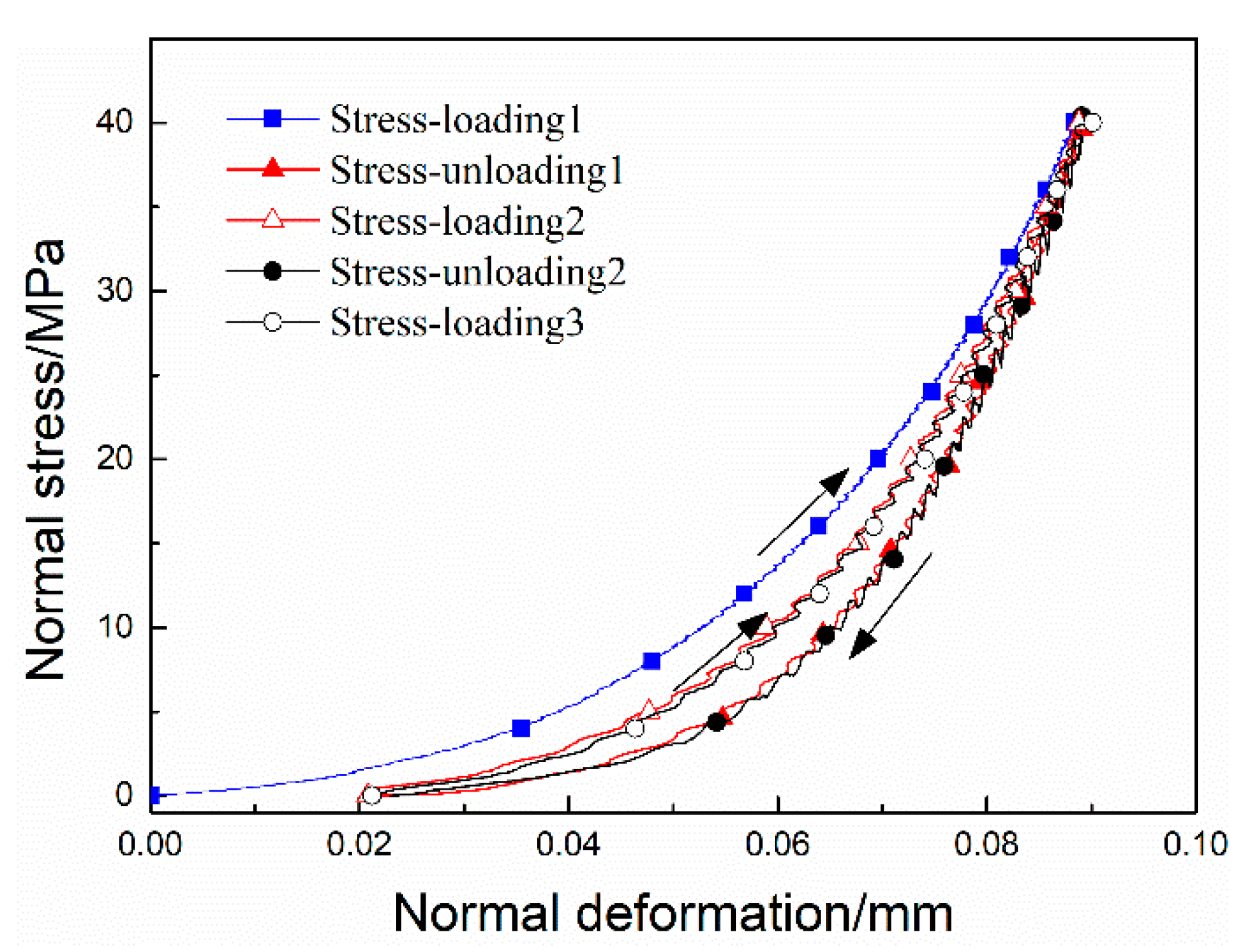
Figure 4 shows the curves of normal stress-normal deformation of intact and jointed sample under stress-loading and -unloading condition. Figure 5 shows the curves of normal stress-normal deformation of jointed sample under multicycle stress-loading and -unloading condition. In Figure 4, the intact and jointed sample exhibit a hysteresis loop between load- and unload-path. For the intact and jointed sample, the irreversible deformation is observed after unloading, and that of jointed sample significantly greater than the intact sample. However, after the first cycle of loading and unloading, the following cycle curves overlap as shown Figure 5. These indicate that the jointed sample exhibits non-linear elastic response of normal deformation under hydrostatic pressure as in the experimental result of Cook [36].
3.2. N2 Injection Test of Jointed Sample
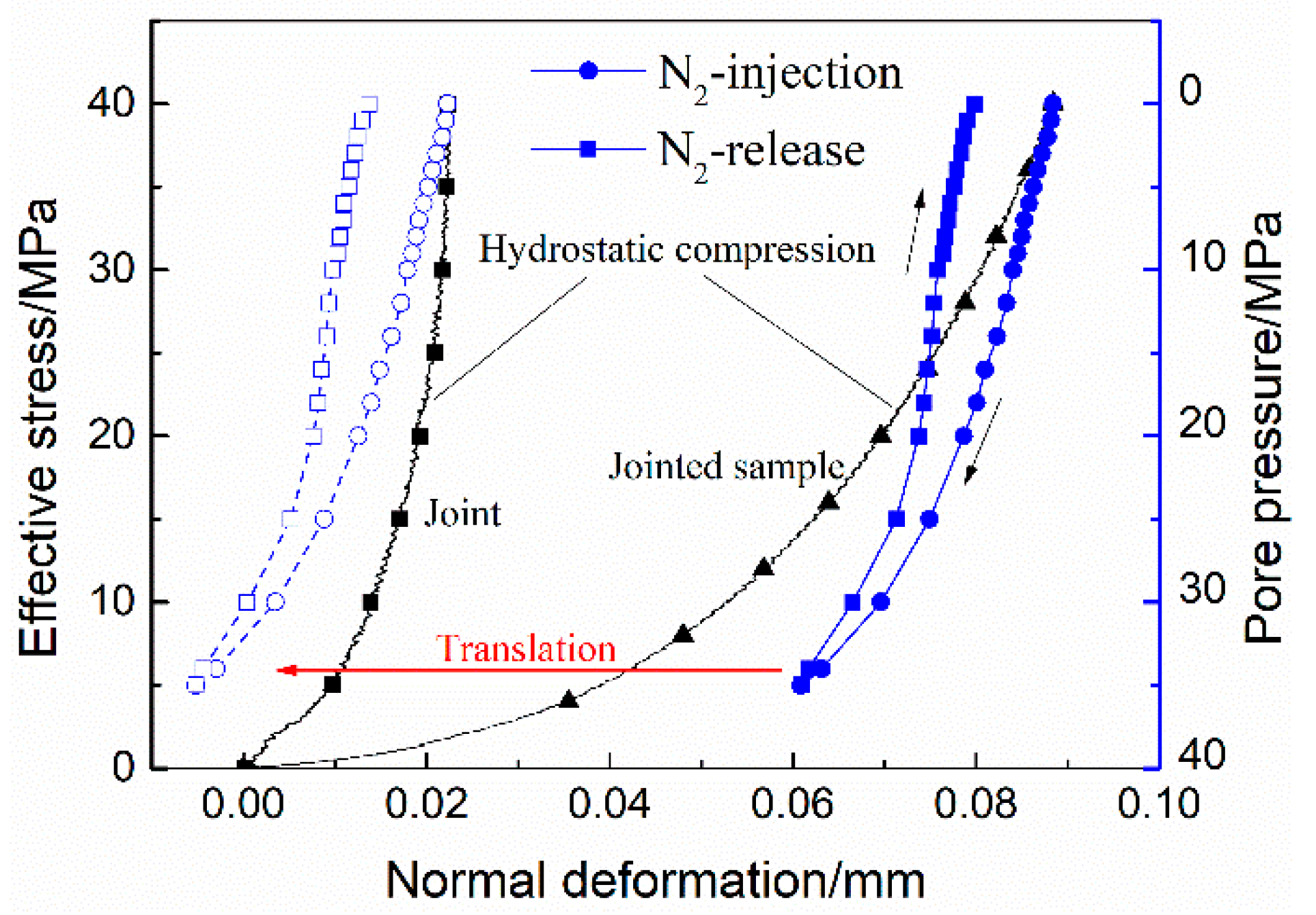
In the N2 injection test, the pressure balanced injection was adopted and the hydrostatic pressure is constant at 40 MPa. Figure 6 shows the curve of the relative normal deformation of jointed sample () with effective normal stress/pore pressure. With decreasing of effective normal stress (i.e., increasing of pore N2 pressure), the jointed sample continuously dilate and the normal deformation lags behind the curve of hydrostatic compression. To facilitate comparison between and the normal deformation of the joint and to find their differences in variation trend, the relative deformation of jointed sample was translated. It exceeds the normal deformation of the joint under hydrostatic compression. However, during N2 releasing, the jointed sample continuing to compress with the decreasing of pore pressure and the variation trend is similar to that of the joint under hydrostatic compression. When the pressure of N2 completely dissipates, a remarkable amount of dilation is observed. These indicate that pore N2 pressure significantly affects the deformation of the joint and the host rock surrounding the joint.
3.3. Water Injection Test of Jointed Sample
In the water injection test, the pressure balanced injection and the constant pressure rate injection were all adopted and the hydrostatic pressure is constant at 40 MPa. Figure 7 and Figure 8 show the results of the pressure balanced injection and the constant pressure rate injection, respectively.
For the pressure balanced injection (as shown in Figure 7), with decreasing of effective normal stress, the jointed sample also continuously dilates and the normal deformation lags behind the curve of hydrostatic compression. If the relative deformation of jointed sample was translated and compared with the joint deformation under hydrostatic compression, it also exceeds the normal deformation of the joint. At the early stage of the injection, the normal deformation of jointed sample basically along the curve of hydrostatic compression, gradually deviates from the curve with the increasing of pore water pressure. During pressure reduction, the relative normal deformation of jointed sample linear increase to the initial value. When the pressure of water completely dissipates, no remarkably residual dilation of jointed sample is observed. These indicate pore water pressure also significantly affects the deformation of the joint. The effect of pore water pressure on the host rock surrounding the joint is weaker than N2.
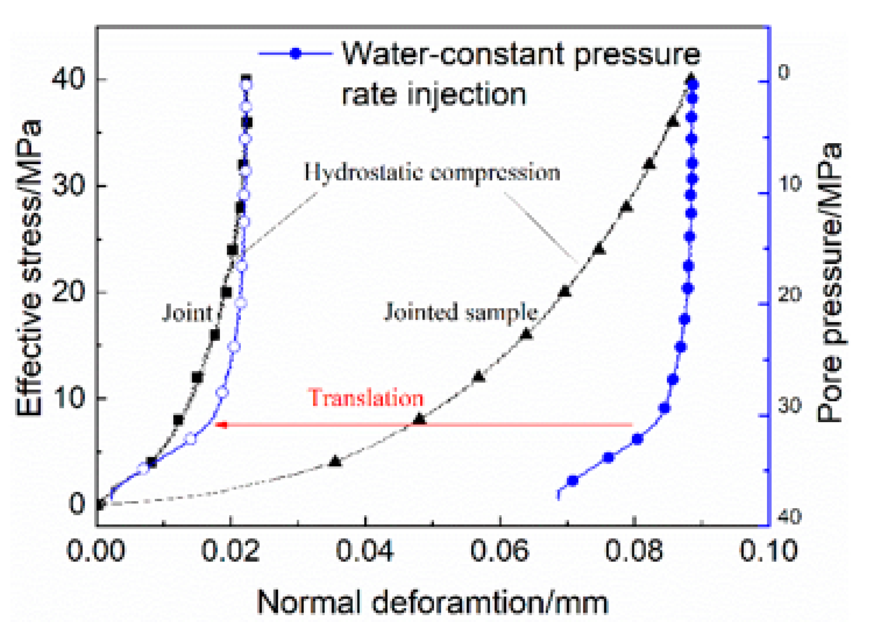
For the constant pressure rate injection (as shown in Figure 8), the pore water pressure did not significantly affect the relative normal deformation of jointed sample with pore water pressure less than 20 MPa. With increasing of pore water pressure, the relative normal deformation of jointed sample affected by pore water pressure was significantly enhanced. The relative normal deformation of jointed sample during injection is lags behind the normal deformation of jointed sample and the joint under hydrostatic compression. At high pore pressure, the relative normal deformation of jointed sample rapidly decreases with the pore pressure, and it coincides with the curves of the joint under hydrostatic compression when the pore pressure more than 35 MPa. This indicates that water has little effect on the host rock surrounding the joint, and the effect of pore water pressure on the joint is remarkable. Meanwhile, as the permeability of granite is lower than that with a fracture/joint [37], the host rock was viewed as impermeable within 1 h for the constant pressure rate injection. For the constant pressure rate injection, pore pressure mainly affects the joint.
The relative deformation of jointed sample at the initial stage of the pressure balanced injection and at the last stage of the constant pressure rate injection coincide with the normal deformation curve of the joint under hydrostatic compression. This indicates that the effect of pore water pressure on the joint follows the Terzaghi’s effective stress and is consistent with the curve of the joint under hydrostatic compression. During fluid balanced injection, pore fluid pressure affects the deformation of host rock.
4. Discussion
The above experimental results indicate that the pore fluid pressure significantly affects the normal deformation of jointed sample and the joint. The influence of pore fluid pressure on the joint and host rock were analyzed and quantified in this section.
4.1. Impacts of Pore Fluid Pressure on Jointed Sample
When fluid was injected into the jointed sample, the normal deformation of the jointed sample was significantly influenced by pore pressure, as show in Figure 6, Figure 7 and Figure 8. In the water constant pressure rate injection, the relative normal deformation of jointed sample exhibits a threshold pressure for opening of the joint as the result of in-situ experiment on fracture [26]. In this study, the threshold pressure results from the low permeability of the matched joint under high normal stress, which limit liquid water flow into the space between two joint planes in a short time. When the injection pressure exceeds the threshold pressure, water flows into the space between two joint planes. Pore pressure builds up rapidly, and the joint rapidly opens. Due to the limitation of injection time, the effect of pore pressure on host rock surrounding the joint is negligible.
The effective stress is a conceptual average stress and is defined as the combinations of total stress and pore pressure which produce effects [38]. The generalization effective stress, is expressed as:
where, is the total stress tensor, is the effective stress coefficient, . The effective stress coefficient can be considered the ratio of the area of applied pressure to the total area base on the definition of effective stress law. In this case, the joint is a throughout fracture, so fluid could exist in the total area of joint. Thus, it is reasonable that takes 1. The generalization effective stress can be expressed as Terzaghi’s effective stress:
This deduction is in agreement with the experimental results that the action of pore fluid pressure on the joint follows the Terzaghi’s effective stress law.
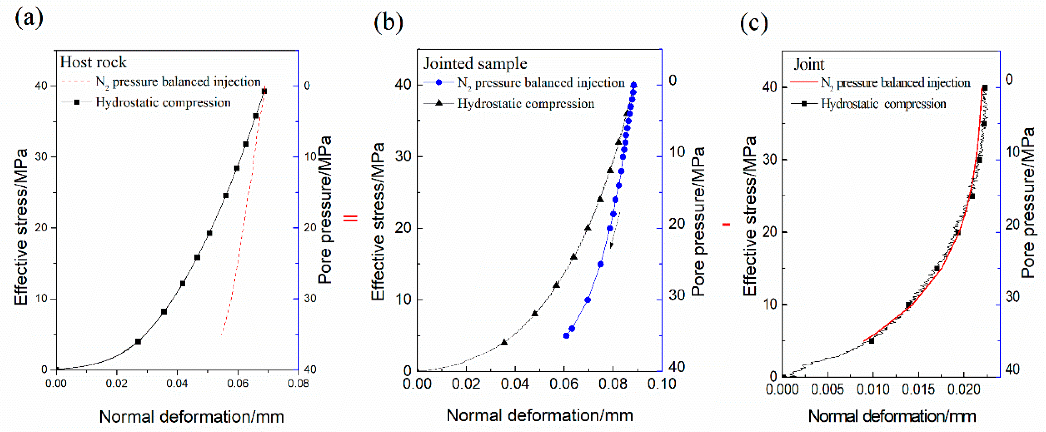
For the balanced pressure injection, the duration is longer than that of the constant pressure rate injection, the relative normal deformation of jointed sample being obviously larger than that of the joint under hydrostatic compression, as show in Figure 7 and Figure 8. This indicates that pore fluid pressure influences the deformation of host rock, and this influence cannot be ignored. The influence of pore N2 pressure on host rock is more significant than water as the lower viscosity coefficient of N2. Therefore, the relative deformation of jointed sample () during fluid injection consists of the opening of joint () and the dilation of host rock () as shown in Figure 9.
4.2. Quantification the Normal Deformation of the Joint Under Pore Pressure Condition
The normal deformation of the joint under normal stress can be quantified by several mathematical models, such as the hyperbolic model developed by Barton and Bandis [13] (hereinafter, BB model), the generalized exponential model [2] (hereinafter, Malama model), and so on. The BB model and the Malama model are characteristic of simplicity and clarity in parameters. Thus, these two models are used to compare to the experimental data of the joint under hydrostatic compression. According to Barton and Bandis et al. (1985), the BB model is given by Equation (5),
where is the normal deformation, is the maximum closure of the joint, is the initial stiffness, is the normal stress. According to Malama and Kulatilake (2003), the Malama model is given by Equation (6),
where is the normal deformation, is the maximum closure of the joint, is the half-closure stress (the normal stress when the normal deformation arrive half-maximum closure), n is the parameter, . Based on our experimental data, the key parameters of the joint are compiled in Table 3. The curves of stress-deformation based on the BB model, Malama model and experimental data are presented in Figure 10. The error sum of squares in normal deformation between the BB model/Malama model and experimental result is 0.025/0.00042. The Malama model is better in describing the normal deformation characteristics of the joint than the BB model. Thus, the Malama model was adopted to analyze the normal deformation of the joint in the injection test. Section 4.1 indicates the normal deformation of the joint following Terzaghi’s effective stress law at the action of pore pressure. Because the jointed sample exhibits non-linear elastic response under normal stress, it is reasonable to assume that the normal deformation path of jointed sample is the same when stress-loading and -unloading. According to the Terzaghi’s effective stress, an improved Malama model can be modified:
Because the relatively normal deformation of the jointed sample during fluid injection consists of the opening of joint plane and the dilation of host rock. The normal deformation of host rock under the action of pore pressure can be calculated by Equation (8):
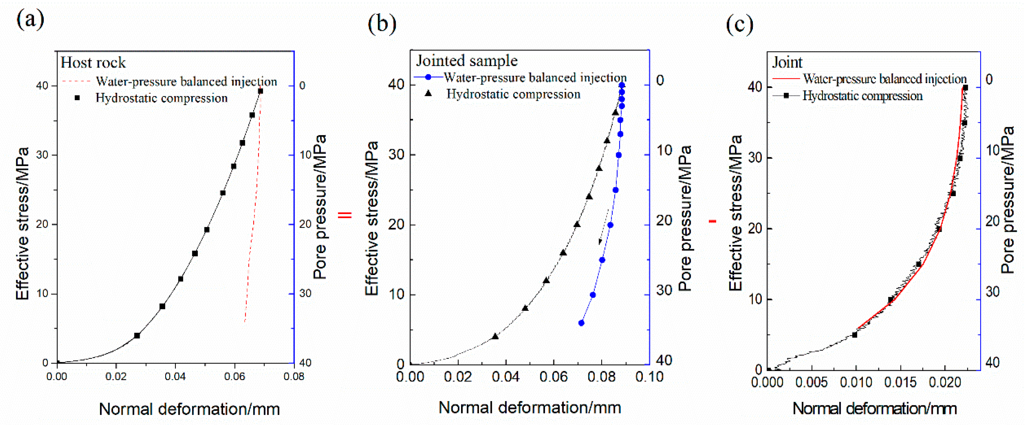
where, is the relative normal deformation of host rock, is the relative normal of jointed sample and measured in the injection test. According to Equation (8), the normal deformation of host rock in N2 and the water injection test were calculated and shown in Figure 11 and Figure 12, respectively.
As shown in Figure 11 and Figure 12, the normal deformation of host rock has a linear relationship with pore pressure. When the confining pressure maintains at 40 MPa, host rock dilates with the increasing of pore pressure (decrease of effective stress). The effect of N2 on host rock is obviously larger than water. However, the total amount of host rock deformation during N2/water injection is far less than that during hydrostatic compression. The differences in the effect on host rock between N2 and water may be a result of the difference in viscosity, where N2 has a lower viscosity than water, it is easy to penetrate the host rock and build-up the pore pressure inside host rock. Host rock may be unsaturated when the pore pressure of the joint achieves a balance. The pore N2 pressure is higher than the pore water pressure and it affects the deformation of the host rock. Thus, the dilation of host rock under N2 injection is obviously larger than water.
4.3. Quantification of Host Rock Deformation under Pore Pressure Condition
Although granite has a low porosity, it is a porous material and its mechanical behavior is thus significantly affected by pore pressure [39]. The deformation behavior of rock under pore fluid pressure could described by the pore elastic theory [40,41]:
where, is Lame elastic constant, is shear modulus, is the stress tensor, is the strain tensor, and is the effective stress coefficient. of host rock could derived by Equation (9):
In this test, the sample was subjected to a constant hydrostatic pressure and pore pressure, . Considering granite is homogeneous, , . The estimated value of host rock could be expressed as:
where, is the normal deformation of host rock during fluid injection, is the height of intact sample, . and are basic mechanical parameters and compiled in Table 2. When the estimated value is constant, the normal deformation of host rock is proportional to the pore fluid pressure. Thus, the normal deformation of host rock has a linear relationship with pore pressure. According to the calculated normal deformation of host rock during N2 and water pressure balanced injection, the estimated value is 0.412, 0.168 respectively. From the range of , these estimated values of are reasonable for the host rock. Noting that whether the rock is saturated during reinjection is currently uncertain, the actual 𝛼 of host rock needs further study. This indicates the improved Malama model is reasonable and suitable to describe the normal deformation behavior of the joint under pore fluid pressure condition. In addition, in the process of HM, the effect of pore fluid pressure on host rock is non-negligible, and the degree of its influence is related to types of fluid.
5. Conclusions
The effect of pore fluid pressure on normal deformation behavior of a granite matched joint was investigated by laboratory experiments. Several main conclusions can be drawn; they are as follows:
The matched granite joint has a characteristic of non-linear elastic response under hydrostatic compression. The Malama model is closer to the curve of normal deformation versus normal stress than the BB model. The error sum of squares in normal deformation between the BB model/Malama model and the experimental result is 0.025/0.00042.
In water constant pressure rate injection, experimental results indicate that the action of pore fluid pressure on normal deformation of the joint follows the Terzaghi’s effective stress law. Due to low permeability of the joint under high normal stress, a threshold pore pressure is observed in the opening of the joint. When the duration of injection is enlarged, the influence of pore pressure on deformation of host rock is observed.
The effect of pore fluid pressure on the normal deformation of the jointed sample consists of two parts: the opening of the joint () and the dilation of host rock (). The relative normal deformation of the joint could be quantitated by the Malama model and the Terzaghi’s effective stress law, and the normal deformation of host rock can be quantified by pore elastic theory.
The relative normal deformation of host rock linearly increased with the pore fluid pressure and the effect of N2 on host rock is obviously larger than water. In the process of hydro-mechanical coupling, the effect of pore fluid pressure on host rock is non-negligible, and the degree of its influence is related to types of fluid.
Author Contributions
Q.Z. and X.L. conceived and designed the experiments; Q.Z. performed the experiments; Q.Z. and B.B. analyzed the data; S.H., X.L. and L.S. contributed reagents/materials/analysis tools; Q.Z. wrote the paper.
Funding
This research is supported by the National Key Research and Development Program (No. 2016YFB0600805, 2018YFB0605601), the National Natural Science Foundation of China (No. 41672252), and the General Program of National Natural Science Foundation of China (No. 41472236).
Conflicts of Interest
The authors declare no conflict of interest.
References
- Xia, C.C.; Yue, Z.Q.; Tham, L.G.; Lee, C.F.; Sun, Z.Q. Quantifying topography and closure deformation of rock joints. Int. J. Rock Mech. Min. Sci. 2003, 40, 197–220. [Google Scholar] [CrossRef]
- Malama, B.; Kulatilake, P.H.S.W. Models for normal fracture deformation under compressive loading. Int. J. Rock Mech. Min. Sci. 2003, 40, 893–901. [Google Scholar] [CrossRef]
- Pyrack-Nolte, L. Hydraulic and Mechanical Properties of Natural Fractures in low-Permeability Rock; International Society for Rock Mechanics and Rock Engineering: Montreal, QC, Canada, 1987. [Google Scholar]
- Desai, C.S.; Rigby, D.B. Cyclic Interface and Joint Shear Device Including Pore Pressure Effects. J. Geotech. Geoenviron. Eng. 1997, 123, 568–579. [Google Scholar] [CrossRef]
- Jaeger, J.C.; Cook, N.G.W.; Zimmerman, R. Fundamentals of Rock Mechanics, 4th ed.; John Wiley & Sons: Hoboken, NJ, USA, 2007. [Google Scholar]
- Cappa, F.; Guglielmi, Y.; Rutqvist, J.; Tsang, C.-F.; Thoraval, A. Hydromechanical modelling of pulse tests that measure fluid pressure and fracture normal displacement at the Coaraze Laboratory site, France. Int. J. Rock Mech. Min. Sci. 2006, 43, 1062–1082. [Google Scholar] [CrossRef] [Green Version]
- Rutqvist, J.; Stephansson, O. The role of hydromechanical coupling in fractured rock engineering. Hydrogeol. J. 2003, 11, 7–40. [Google Scholar] [CrossRef] [Green Version]
- Bart, M.; Shao, J.F.; Lydzba, D.; Haji-Soutoudeh, M. Coupled hydromechanical modeling of rock fractures under normal stress. Can. Geotech. J. 2004, 41, 686–697. [Google Scholar] [CrossRef]
- Yang, H.; Xie, S.Y.; Secq, J.; Shao, J.F. Experimental study and modeling of hydromechanical behavior of concrete fracture. Water Sci. Eng. 2017, 10, 97–106. [Google Scholar] [CrossRef]
- Ji, S.H.; Koh, Y.K.; Kuhlman, K.L.; Lee, M.Y.; Choi, J.W. Influence of pressure change during hydraulic tests on fracture aperture. Groundwater 2013, 51, 298–304. [Google Scholar] [CrossRef] [PubMed]
- Kamali-Asl, A.; Ghazanfari, E.; Perdrial, N.; Bredice, N. Experimental study of fracture response in granite specimens subjected to hydrothermal conditions relevant for enhanced geothermal systems. Geothermics 2018, 72, 205–224. [Google Scholar] [CrossRef]
- Vogler, D.; Amann, F.; Elsworth, D. Permeability Evolution in Natural Fractures Subject to Cyclic Loading and Gouge Formation. Rock Mech. Rock Eng. 2016, 49, 3463–3479. [Google Scholar] [CrossRef]
- Barton, N.; Bandis, S.; Bakhtar, K. Strength, deformation and conductivity coupling of rock joints. Int. J. Rock Mech. Min. Sci. Geomech. Abstr. 1985, 22, 121–140. [Google Scholar] [CrossRef]
- Swan, G. Determination of stiffness and other joint properties from roughness measurements. Rock Mech. Rock Eng. 1983, 16, 19–38. [Google Scholar] [CrossRef]
- Sun, Z. Study on the deformation vs stress properties of discontinuous. Chin. J. Rock Mech. Eng. 1987, 4, 287–300. [Google Scholar]
- Sun, G.; Lin, W. The principle of closed deformation of structural plane and elastic deformation constitutive equation of rock mass. Chin. J. Rock Mech. Eng. 1982, 2, 177–180. [Google Scholar]
- Goodman, R.E. Methods of Geological Engineering in Discontinuous Rocks; West Publishing Company: Eagan, MN, USA, 1976. [Google Scholar]
- Rong, G.; Huang, K.; Zhou, C.B.; Wang, X.J.; Peng, J. A new constitutive law for the nonlinear normal deformation of rock joints under normal load. Sci. Chin. Technol. Sci. 2011, 55, 555–567. [Google Scholar] [CrossRef]
- Sharp, J.C.; Maini, Y. Fundamental considerations on the hydraulic characteristics of joints in rock. In Proceedings of the Symposium of Percolation through Fissured Rock, Stuttgart, Germany, 18–19 September 1972. [Google Scholar]
- Sun, Z.; Gerrard, C.; Stephansson, O. Rock joint compliance tests for compression and shear loads. Int. J. Rock Mech. Min. Sci. Geomech. Abstr. 1985, 22, 197–213. [Google Scholar] [CrossRef]
- Yu, J.; Zhao, X.; Zhao, W.; Li, X.; Guan, Y. Improved nonlinear elastic constitutive model for normal deformation of rock fractures. Chin. J. Geotech. Eng. 2008, 30, 1316–1321. [Google Scholar]
- Desai, C.S.; Ma, Y. Modelling of joints and interfaces using the disturbed-state concept. Int. J. Numer. Anal. Method. Geomech. 1992, 16, 623–653. [Google Scholar] [CrossRef]
- Snow, D.T. Anisotropie Permeability of Fractured Media. Water Resour. Res. 1969, 5, 1273–1289. [Google Scholar] [CrossRef]
- Witherspoon, P.A.; Wang, J.S.Y.; Iwai, K.; Gale, J.E. Validity of Cubic Law for fluid flow in a deformable rock fracture. Water Resour. Res. 1980, 16, 1016–1024. [Google Scholar] [CrossRef] [Green Version]
- Amadei, B.; Illangasekare, T. A mathematical model for flow and solute transport in non-homogeneous rock fractures. Int. J. Rock Mech. Min. Sci. Geomech. Abstr. 1994, 31, 719–731. [Google Scholar] [CrossRef]
- Cornet, F.H.; Li, L.; Hulin, J.-P.; Ippolito, I.; Kurowski, P. The hydromechanical behaviour of a fracture: An in situ experimental case study. Int. J. Rock Mech. Min. Sci. 2003, 40, 1257–1270. [Google Scholar] [CrossRef]
- Duan, X.; Li, J.; Liu, J. Numerical simulation of flow motion of fractured rock mass under the interaction of stress field and seepage field. J. Dalian Univ. Technol. 1992, 32, 712–717. [Google Scholar]
- Chen, P.; Zhang, Y. Seepage and stress coupling analysis of fractured rock mass. Chi. J. Rock Mech. Eng. 1994, 13, 299–308. [Google Scholar]
- Runslätt, E.; Thörn, J. Fracture Deformation When Grouting in Hard Rock: In Situ Measurements in Tunnels under Gothenburg and Hallandsås. Available online: http://publications.lib.chalmers.se/records/fulltext/126954.pdf (accessed on 30 June 2018).
- Schweisinger, T.; Svenson, E.J.; Murdoch, L.C. Hydromechanical behavior during constant-rate pumping tests in fractured gneiss. Hydrol. J. 2011, 19, 963–980. [Google Scholar] [CrossRef]
- Nur, A.; Byerlee, J.D. An exact effective stress law for elastic deformation of rock with fluids. J. Geophys. Res. 1971, 76, 6414–6419. [Google Scholar] [CrossRef]
- Brace, W.F.; Martin, R.J. A test of the law of effective stress for crystalline rocks of low porosity. Int. J. Rock Mech. Min. Sci. Geomech. Abstr. 1968, 5, 415–426. [Google Scholar] [CrossRef]
- Berryman, J.G. Effective stress for transport properties of inhomogeneous porous rock. J. Geophys. Res. 1992, 97, 17409–17424. [Google Scholar] [CrossRef]
- Shi, L.; Li, X.; Bing, B.; Wang, A.; Zeng, Z.; He, H. A Mogi-Type True Triaxial Testing Apparatus for Rocks with Two Moveable Frames in Horizontal Layout for Providing Orthogonal Loads. Geotech. Test. J. 2017, 40, 542–558. [Google Scholar] [CrossRef]
- Hu, S.; Li, X.; Bai, B.; Shi, L.; Liu, M.; Wu, H. A modified true triaxial apparatus for measuring mechanical properties of sandstone coupled with CO2-H2O biphase fluid. Greenh. Gas. Sci. Technol. 2017, 7, 78–91. [Google Scholar] [CrossRef]
- Cook, N.G. Natural joints in rock: Mechanical, hydraulic and seismic behaviour and properties under normal stress. Int. J. Rock Mech. Min. Sci. Geomech. Abstr. 1992, 29, 198–223. [Google Scholar] [CrossRef]
- Zoback, M.D.; Byerlee, J.D. The effect of microcrack dilatancy on the permeability of westerly granite. J. Geophys. Res. 1975, 80, 752–755. [Google Scholar] [CrossRef] [Green Version]
- Walsh, J.B. Effect of pore pressure and confining pressure on fracture permeability. Int. J. Rock Mech. Min. Sci. Geomech. Abstr. 1981, 18, 429–435. [Google Scholar] [CrossRef]
- Cheng, C.; Li, X.; Li, S.; Zheng, B. Failure Behavior of Granite Affected by Confinement and Water Pressure and Its Influence on the Seepage Behavior by Laboratory Experiments. Materials 2017, 10, 798. [Google Scholar] [CrossRef] [PubMed]
- Rice, J.R.; Cleary, M.P. Some basic stress diffusion solutions for fluid-saturated elastic porous media with compressible constituents. Rev. Geophys. 1976, 14, 227–241. [Google Scholar] [CrossRef]
- Zhou, X.; Burbey, T.J. Fluid effect on hydraulic fracture propagation behavior: a comparison between water and supercritical CO2-like fluid. Geofluids 2014, 14, 174–188. [Google Scholar] [CrossRef]
Figure 1.
The granite samples. (a) in intact state, (b) in split state.
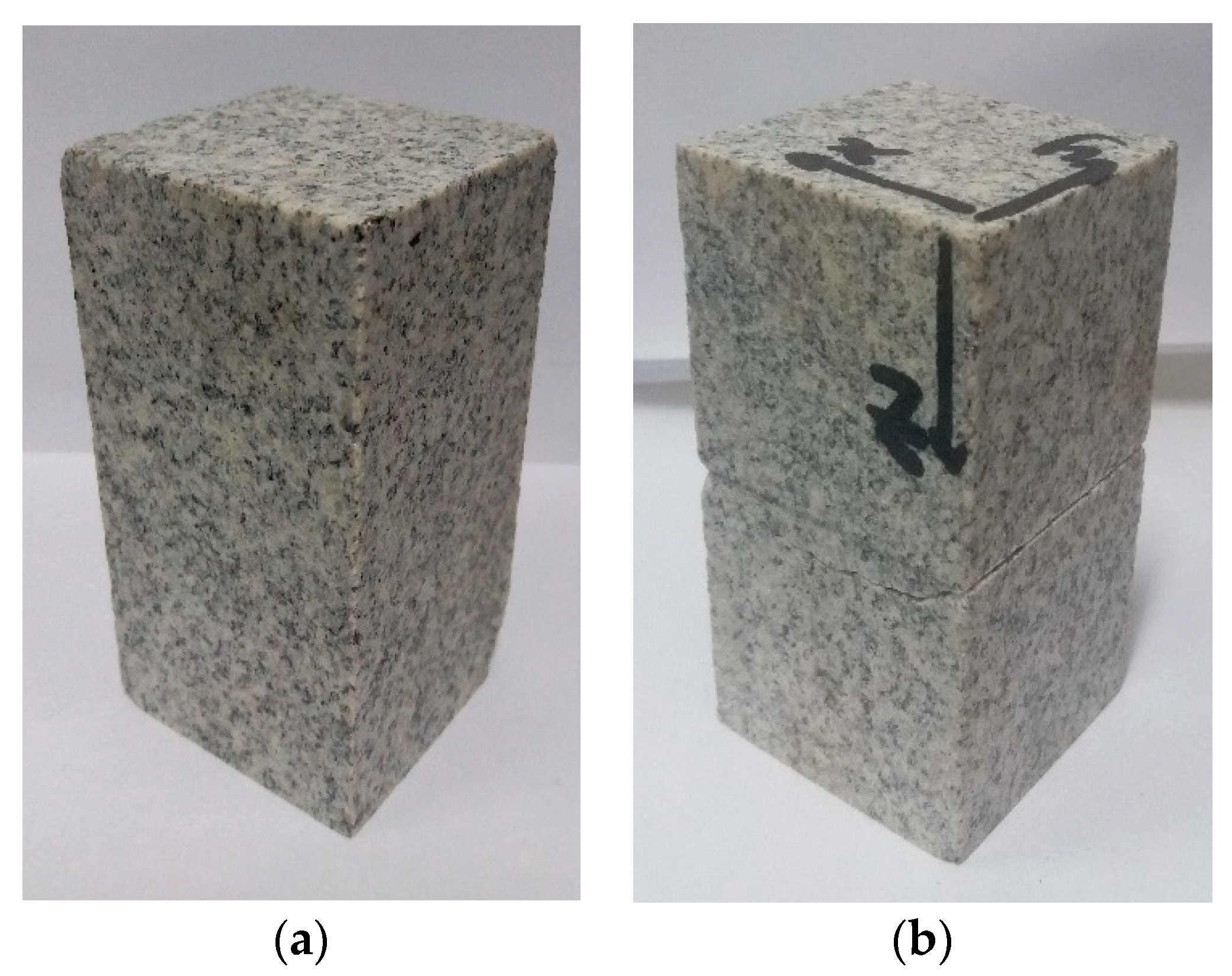
Figure 2.
Schematic diagram of hydrostatic compression and injection test of joint. (a) Diagram of test system; (b) Left view of tested sample; (c) Front view of tested sample.
Figure 2.
Schematic diagram of hydrostatic compression and injection test of joint. (a) Diagram of test system; (b) Left view of tested sample; (c) Front view of tested sample.
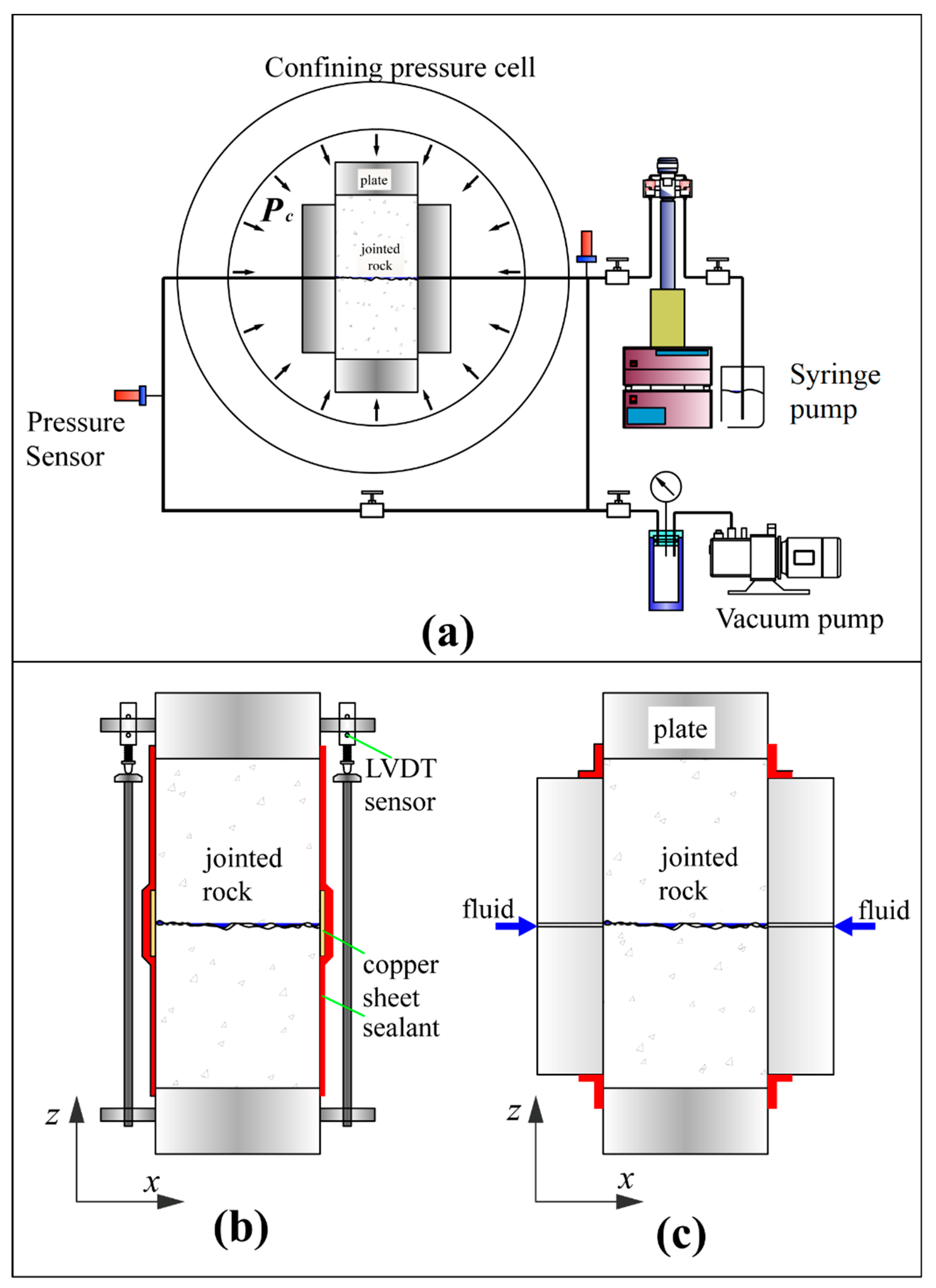
Figure 3.
The curve of normal stress-normal deformation of sample in intact state and in split sate, and joint. The normal deformation of the joint δn was calculated by the normal deformation of jointed sample minus that of intact sample.
Figure 3.
The curve of normal stress-normal deformation of sample in intact state and in split sate, and joint. The normal deformation of the joint δn was calculated by the normal deformation of jointed sample minus that of intact sample.
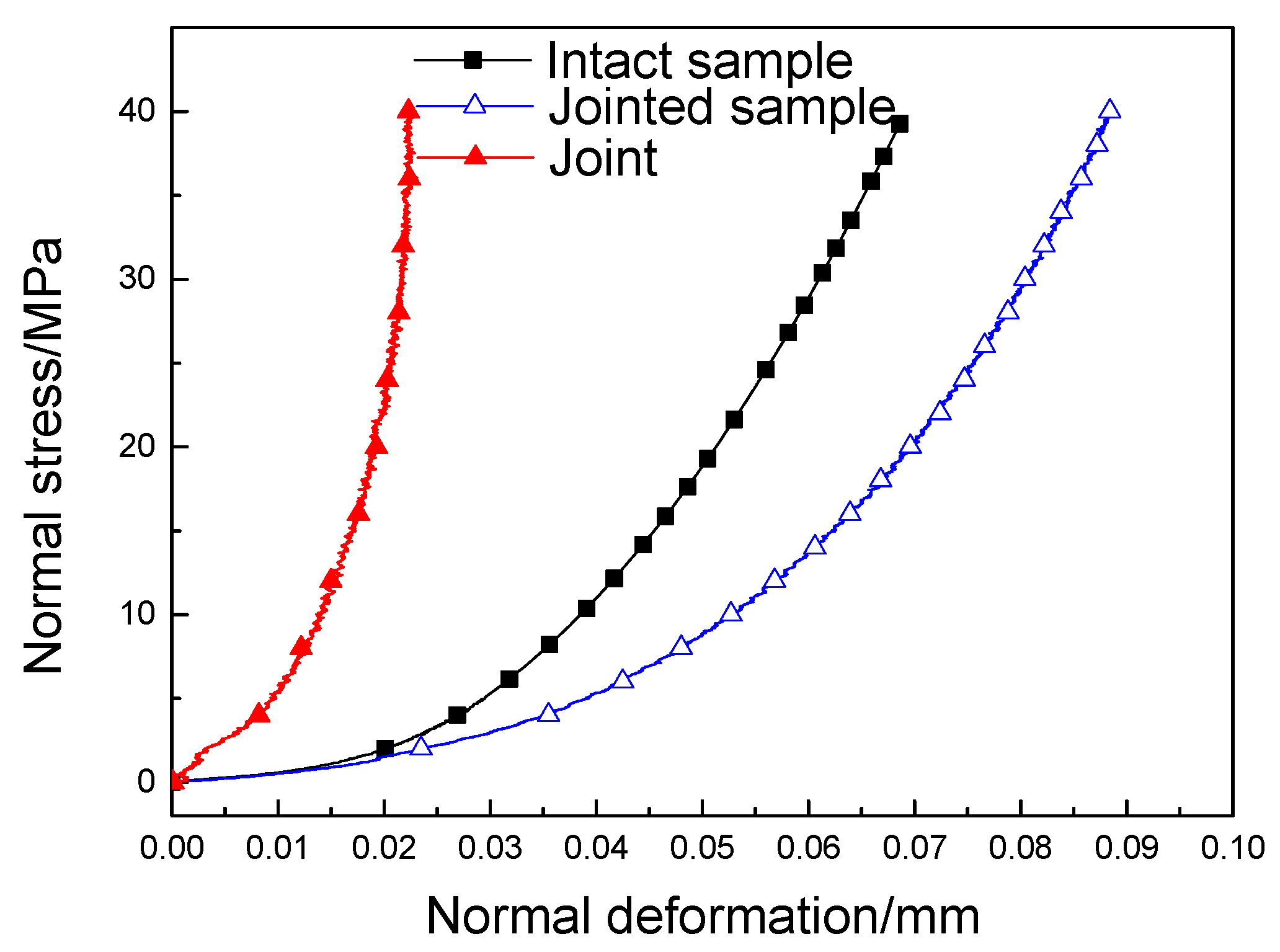
Figure 4.
The curve of normal stress-normal deformation of intact and jointed sample under stress-loading and -unloading.
Figure 4.
The curve of normal stress-normal deformation of intact and jointed sample under stress-loading and -unloading.
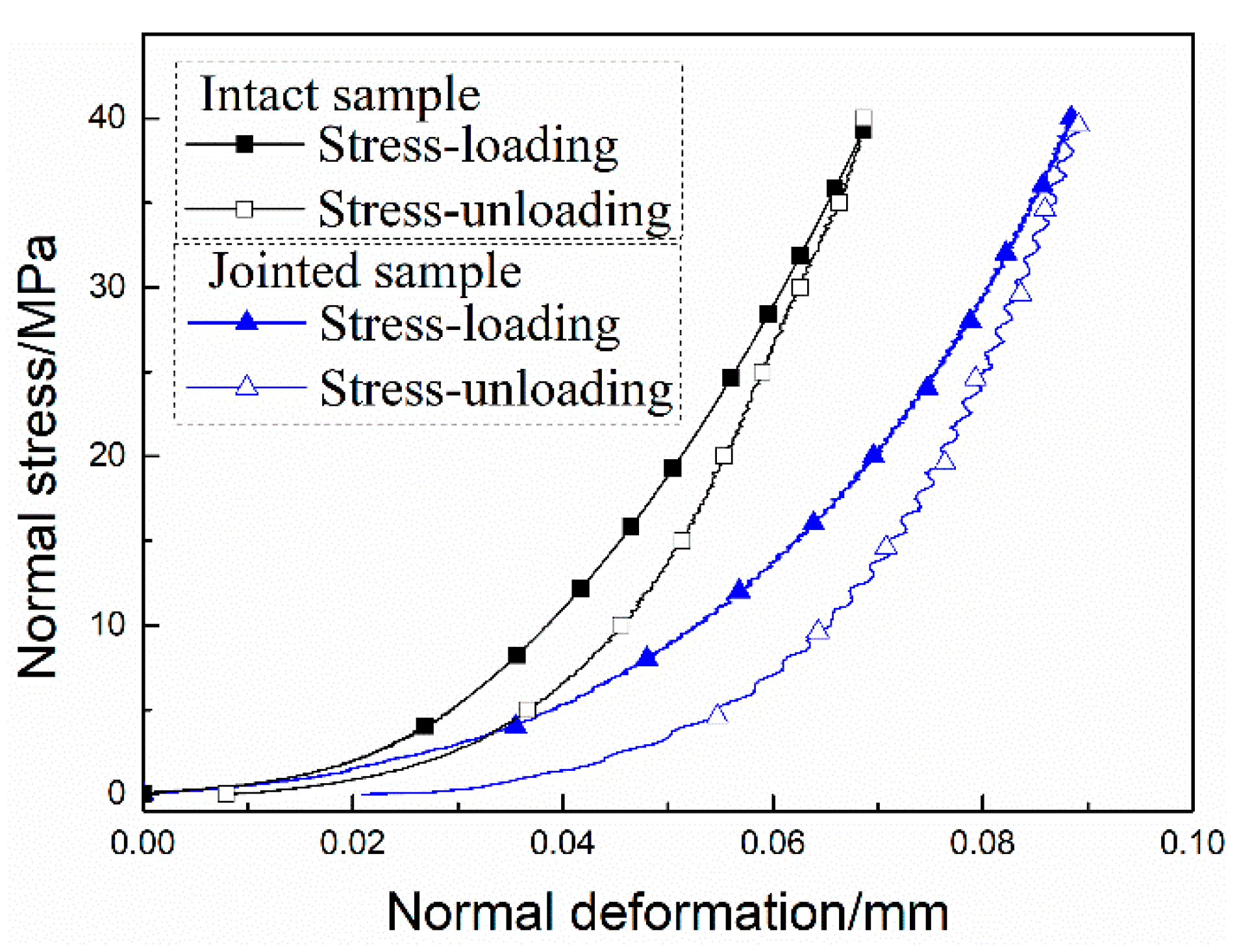
Figure 5.
The curve of normal stress-normal deformation of jointed sample multiple under multicycle stress-loading and -unloading condition.
Figure 5.
The curve of normal stress-normal deformation of jointed sample multiple under multicycle stress-loading and -unloading condition.

Figure 6.
The relative normal deformation of jointed sample during N2 injection and release.

Figure 7.
The relative normal deformation of jointed sample during the water injected in pressure balanced injection.
Figure 7.
The relative normal deformation of jointed sample during the water injected in pressure balanced injection.
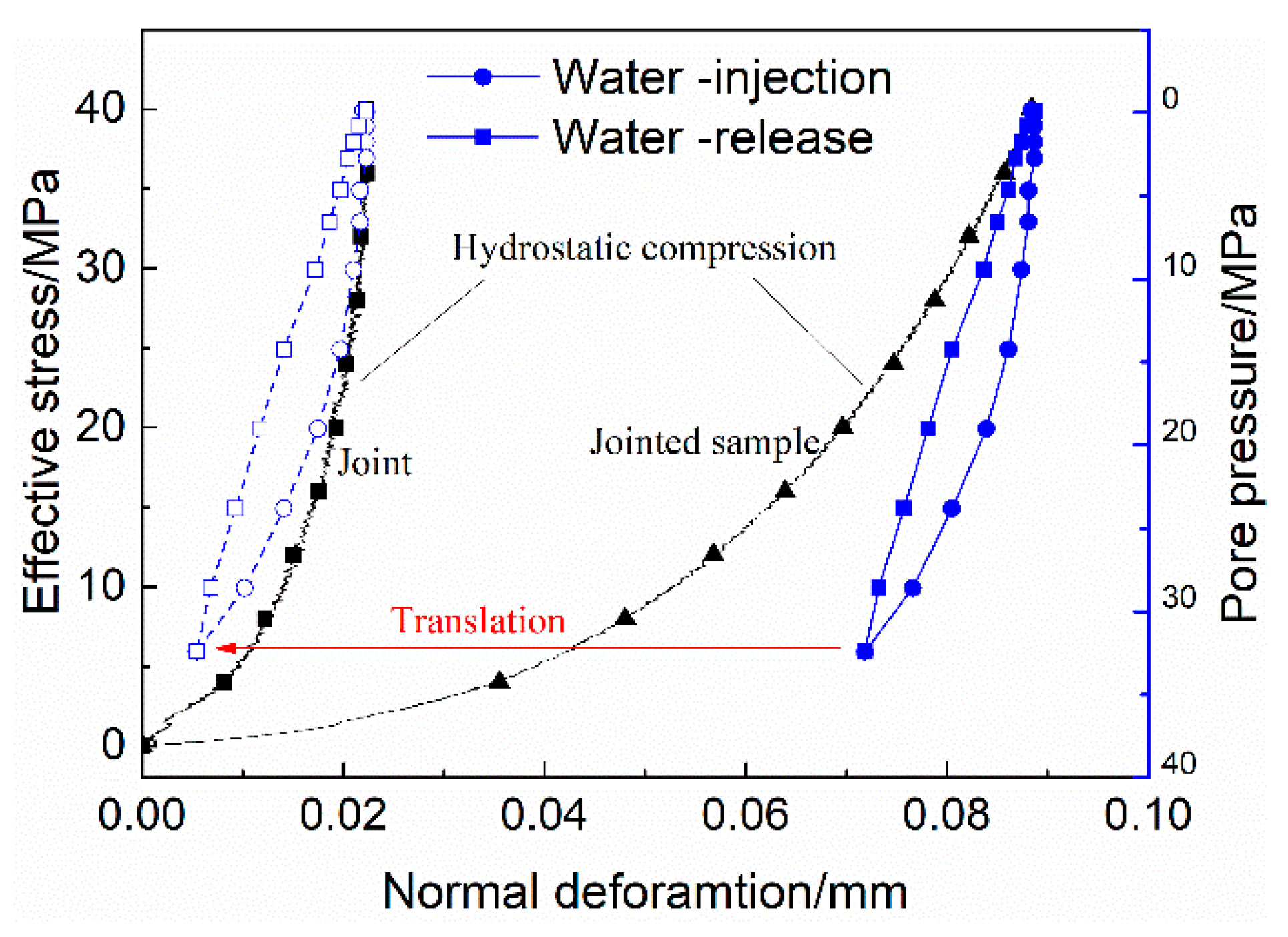
Figure 8.
The relative normal deformation of jointed sample during the water injected in constant pressure rate injection.
Figure 8.
The relative normal deformation of jointed sample during the water injected in constant pressure rate injection.

Figure 9.
Schematic diagram of the normal deformation of jointed sample affected by pore pressure.
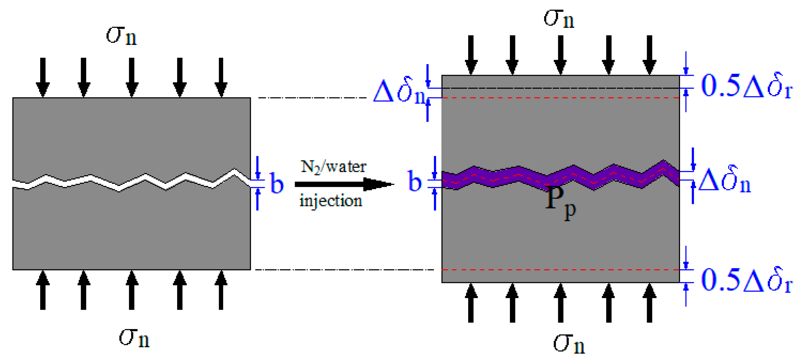
Figure 10.
Comparison between experimental data of the joint and previous models for normal deformation versus normal stress.
Figure 10.
Comparison between experimental data of the joint and previous models for normal deformation versus normal stress.
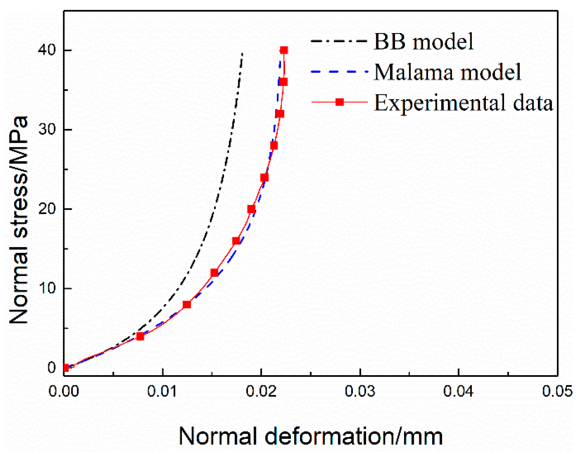
Figure 11.
Decomposition of normal deformation of jointed sample induced by pore N2 pressure: (a) component of host rock; (b) total normal deformation of jointed sample; and (c) component of the joint.
Figure 11.
Decomposition of normal deformation of jointed sample induced by pore N2 pressure: (a) component of host rock; (b) total normal deformation of jointed sample; and (c) component of the joint.

Figure 12.
Decomposition of normal deformation of jointed sample induced by pore water pressure: (a) component of host rock; (b) total deformation of jointed sample; and (c) component of the joint.
Figure 12.
Decomposition of normal deformation of jointed sample induced by pore water pressure: (a) component of host rock; (b) total deformation of jointed sample; and (c) component of the joint.

Table 1.
The composition of granite.
| Minerals | Quarts | Albite | Microcline | Muscovite | Orthoclase |
|---|---|---|---|---|---|
| wt % | 27.51 | 30.83 | 20.60 | 13.69 | 7.37 |
Table 2.
Mechanical parameter of intact granite.
| Size/mm | Uniaxial Strength/MPa | Tensile Strength/MPa | Elasticity Modulus/GPa | Poisson‘s Ratio | Lame Elastic Constant | Shear Modulus |
|---|---|---|---|---|---|---|
| 50 × 50 × 100 | 172.5 | 4.59 | 57.29 | 0.226 | 23.36 | 19.27 |
Table 3.
The parameters of the joint derived from experimental data.
| Maximum Normal Stress σmax/MPa | Half-Closure Stress σ1/2/MPa | Maximum Closure δmax/mm | Initial Normal Stiffness Kni/MPa·mm−1 | Parameter n |
|---|---|---|---|---|
| 40 | 6.76 | 0.0223 | 516.31 | 1 |
© 2018 by the authors. Licensee MDPI, Basel, Switzerland. This article is an open access article distributed under the terms and conditions of the Creative Commons Attribution (CC BY) license (http://creativecommons.org/licenses/by/4.0/).
Share and Cite
MDPI and ACS Style
Zhang, Q.; Li, X.; Bai, B.; Hu, S.; Shi, L. Effect of Pore Fluid Pressure on the Normal Deformation of a Matched Granite Joint. Processes 2018, 6, 107. https://doi.org/10.3390/pr6080107
AMA Style
Zhang Q, Li X, Bai B, Hu S, Shi L. Effect of Pore Fluid Pressure on the Normal Deformation of a Matched Granite Joint. Processes. 2018; 6(8):107. https://doi.org/10.3390/pr6080107
Chicago/Turabian StyleZhang, Qiang, Xiaochun Li, Bing Bai, Shaobin Hu, and Lu Shi. 2018. "Effect of Pore Fluid Pressure on the Normal Deformation of a Matched Granite Joint" Processes 6, no. 8: 107. https://doi.org/10.3390/pr6080107
Note that from the first issue of 2016, this journal uses article numbers instead of page numbers. See further details here.