Numerical Simulation of a New Porous Medium Burner with Two Sections and Double Decks


School of Resource, Environment and Safety Engineering, Hunan University of Science and Technology, Xiangtan 411201, China
*
Author to whom correspondence should be addressed.
Processes 2018, 6(10), 185; https://doi.org/10.3390/pr6100185
Submission received: 11 July 2018
/
Revised: 14 September 2018
/
Accepted: 26 September 2018
/
Published: 6 October 2018
(This article belongs to the Special Issue Transport of Fluids in Nanoporous Materials)
Abstract
:Porous medium burners are characterized by high efficiency and good stability. In this study, a new burner was proposed based on the combustion mechanism of the methane-air mixture in the porous medium and the preheating effect. The new burner is a two-section and double-deck porous medium with gas inlets at both ends. A mathematical model for the gas mixture combustion in the porous medium was established. The combustion performance of the burner was simulated under different equivalence ratios and inlet velocities of premixed gas. The methane combustion degree, as well as the temperature and pressure distribution, was estimated. In addition, the concentrations of emissions of NOx for different equivalence ratios were investigated. The results show that the new burner can not only realize sufficient combustion but also save energy. Furthermore, the emission concentration of NOx is very low. This study provides new insights into the industrial development and application of porous medium combustion devices.
1. Introduction
Nowadays, a lot of low-grade combustible gases are not effectively used. Direct emission of these gases will result in severe energy dissipation and environment pollution. Porous media have many advantages such as good storage, conduction and radiation of heat, and explosion suppression, etc. These features help the porous medium to achieve super-adiabatic combustion [1,2]. Porous medium combustion technology presents a new type of combustion. Compared with traditional combustion technology, it has a larger combustion limit, higher combustion efficiency, and lower pollutant emission [3,4,5,6]. Therefore, porous medium combustion technology is suitable for the utilization of low-calorific-value gases such as low-concentration gas, blast furnace gas, biomass gas, and landfill gas. Based on the chemical kinetic model of the Gibbs minimum free energy theory, Slimane et al. established a mathematical model to simulate the combustion of hydrogen sulphide in porous medium. The composition of combustion products and combustion limit were numerically determined [7]. The combustion of the propane-air mixture was comprehensively investigated by using the ceramic material of honeycomb foam as the porous medium [8]. The temperature of the gas was much higher than that of the adiabatic flame, which was attributed to the internal heat recirculation. Hayashi simulated gas mixture combustion in a porous medium using a three-dimensional mathematical model [9]. The results showed that the flame tended to spread to the combustion zone with lowest air proportion. Hayashi suggested that the pore size of the porous medium should be properly reduced to avoid tempering. Kotani et al. proposed a two-layer porous medium burner [10]. The results showed that the space structure mutation of the junction plane of two different porous media can stabilize the main body of the flame in the flame support layer. Pereira et al. studied the energy focus-ability of a gas mixture in a burner with two-layer porous media [11]. The results showed that the excess temperature is a function of the modified Lewis number, the porosity of the porous medium, and the gas thermal conductivity ratio of solid to gas. Mital et al. concluded that the radiant heat efficiency in the outlet of the burner can reach 30% [12]. According to the one-step chemical reaction of the methane-air mixture, the one-dimensional concentration and flame velocity field were calculated, and the temperature distribution of the flame under different optical thicknesses was obtained [13]. Based on the multistep reaction model, the gas-solid energy equation was established, and the combustion reaction was simulated [14]. Also, the thermal conductivity, volume heat transfer coefficient, and outlet boundary condition of the porous medium were studied.
The influences of the combustion equivalence ratio of the gas mixture and steady airflow velocity on the combustion efficiency were experimentally studied by Wang Enyu [15]. The results showed that the combustion and flow of gas can be improved by using a gradient structure. The characteristics of combustion, pollutant emission, heat diffusion, and resistance in gradually varied porous media (GVPM) were studied, and a GVPM gas-fired boiler was designed [16]. The results revealed that the GVPM burner has the merits of lower NOx and CO emission, higher heat diffusion, and lower resistance. A “volume mean transport equation” of premixed combustible gas flow in isotropic porous medium was proposed by Du [17,18]. Using this equation, he simulated the super-adiabatic combustion of the gas flow in a porous medium burner and found that the reciprocating flow of premixed combustible gas in porous medium has greater advantages than the single-direction flow. The effect of the characteristic parameters of the porous medium on the combustion temperature and pressure can be found in the literature [19,20,21]. The industrial applications and numerical simulation of premixed gas combustion in a porous medium were studied in the literature [22]. The results showed that a square burner can achieve a stable combustion of premixed gases, but it is more demanding in terms of working conditions, and there is a problem of uneven combustion. Circular burners are recommended for industrial applications. The excess enthalpy flames stabilized in a radial multichannel as a model of a cylindrical radial-flow porous medium burner were experimentally and theoretically studied [23]. The result showed that the multichannel flames had excess combustion velocities due to heat recirculation via the channel walls. The stabilization diagram of premixed methane-air flames in finite porous medium under a uniform ambient temperature was numerically studied [24]. The results showed that both stable and unstable solutions, for upper and lower flames, either exist on the surface or submerged in the porous matrix. The conversion of nitric oxide inside a porous medium was investigated in the literature [25]. The effects of equivalence ratio and flow velocity on the flame stabilization were investigated. At the same time, the NOx and TFN (total fixed nitrogen) conversion ratios and temperature profiles along the burner were obtained. The flame propagation and stationary mechanism in single/double-layer porous medium burners were studied by Zhao [26]. The results showed that the double-layer porous medium burner can realize stable standing in the vicinity of the material interface, which can effectively prevent tempering and stripping. It was also found that the burner with multiple sections or double layers would more easily achieve the above objectives than the burner with a single direction or single layer. The combustion characteristics of gaseous fuels with low calorific value in a two-layer porous burner were numerically simulated [27]. The results showed that OH and O radicals are most actively involved in combustion. OH-involved elementary reactions are significantly faster than O-involved elementary reactions. NO is the only NOx species which is significantly presented in the exhaust gases. The concentrations of NO2 and N2O never exceeded 1 mg/m3. The performance characteristics of premixed inert porous burners were numerically simulated [28]. The results indicated that the flow, temperature, and concentration fields of species appear to be approximately one-dimensional. Compared with the traditional burner, the chemical reaction zone is extended in the porous medium burner, while the gas temperature gradient near the flame zone is reduced. Premixed natural gas combustion in porous inert media was numerically studied [29]. The results showed that the radiation of the solid and the heat exchange between gas and solid are the two main factors impacting the combustion performance of porous inert media burners.
Based on the wide application of porous medium burners with a two-section structure (“i.e., ordinary burner”) at present and the advantages of the porous medium burner, the combination of porous media is optimized in this paper. Finally, a new two-section and double-deck porous medium burner with gas inlets at both ends (“i.e., new burner”) is proposed and designed, and the combustion effects of the two kinds of burners are numerically simulated. It is expected that it is simpler and more effective to realize regenerative heat from the combustion zone to the preheating zone, which can effectively solve the problem of low temperature in the vicinity of the burner inlet.
2. Mechanism of Gas Combustion in a Porous Medium
The physical-chemical reaction process of gas combustion is very complicated. Free radicals, ions, electrons molecules, and other transient/intermediate products will be produced during combustion. The flame features of the combustion reaction of CH4-air can be reflected by study of the oxidation reaction mechanism of CH4 [30]. Experimental study on the combustion reaction of N2 and CH4 showed that the oxidation process of CH4 includes a series of free radicals involved in the reaction. According to the element composition of the gas mixture, ions and molecules containing C, H, O, and N are the vast majority of the intermediate products and transient products. These products, especially free radicals, become the activation center in the reaction process, which greatly promotes the continuation, acceleration, and termination of the reaction. The conversion of methane to hydrogen in a porous medium reactor was investigated using fuel with equivalence ratios ranging from 1.5 to 5. The wave velocity, peak combustion temperature, flame structure, volumetric heat release, wave thickness, and hydrogen yield were obtained. The parameters affecting these characteristics included inlet velocity, equivalence ratio, and the thermal conductivity, and the specific heat of the porous medium [31,32,33,34,35].
Generally, when the temperature is high, the oxidation of CH4 can be simplified to CH4→CH3→CH2O→CO→CO2. A continuous combustion reaction increases the temperature, which in turn accelerates the combustion; as a result, the temperature rapidly rises. In this process, hot molecules, ions, and electrons are sharply generated. They carry a huge impulse, momentum, and kinetic energy, and collide with each other. So, the N2 molecules are bound to be impacted by these active particles, and then be decomposed and involved in the oxidation of CH4, which also explains why the pollutants produced by gas combustion in porous media are NOx mostly, in addition to CO2. The design of the new burner fully considers the material structure and the outstanding regenerative properties which can promote chain break and reduce the activation energy in gas combustion reactions. The combustion efficiency is increased, and the combustion of lean gas is promoted.
3. Methodology
3.1. Numerical Model
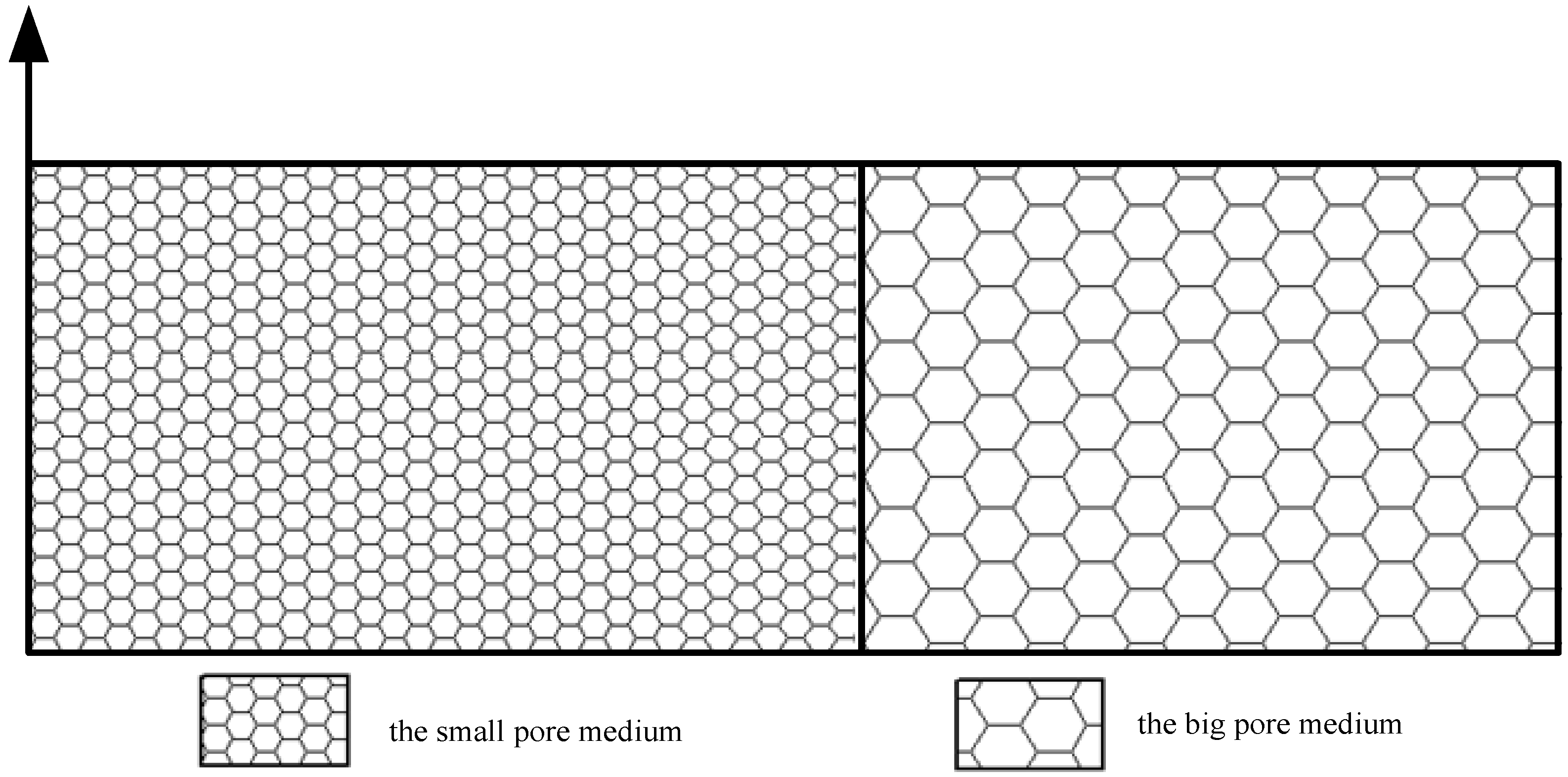
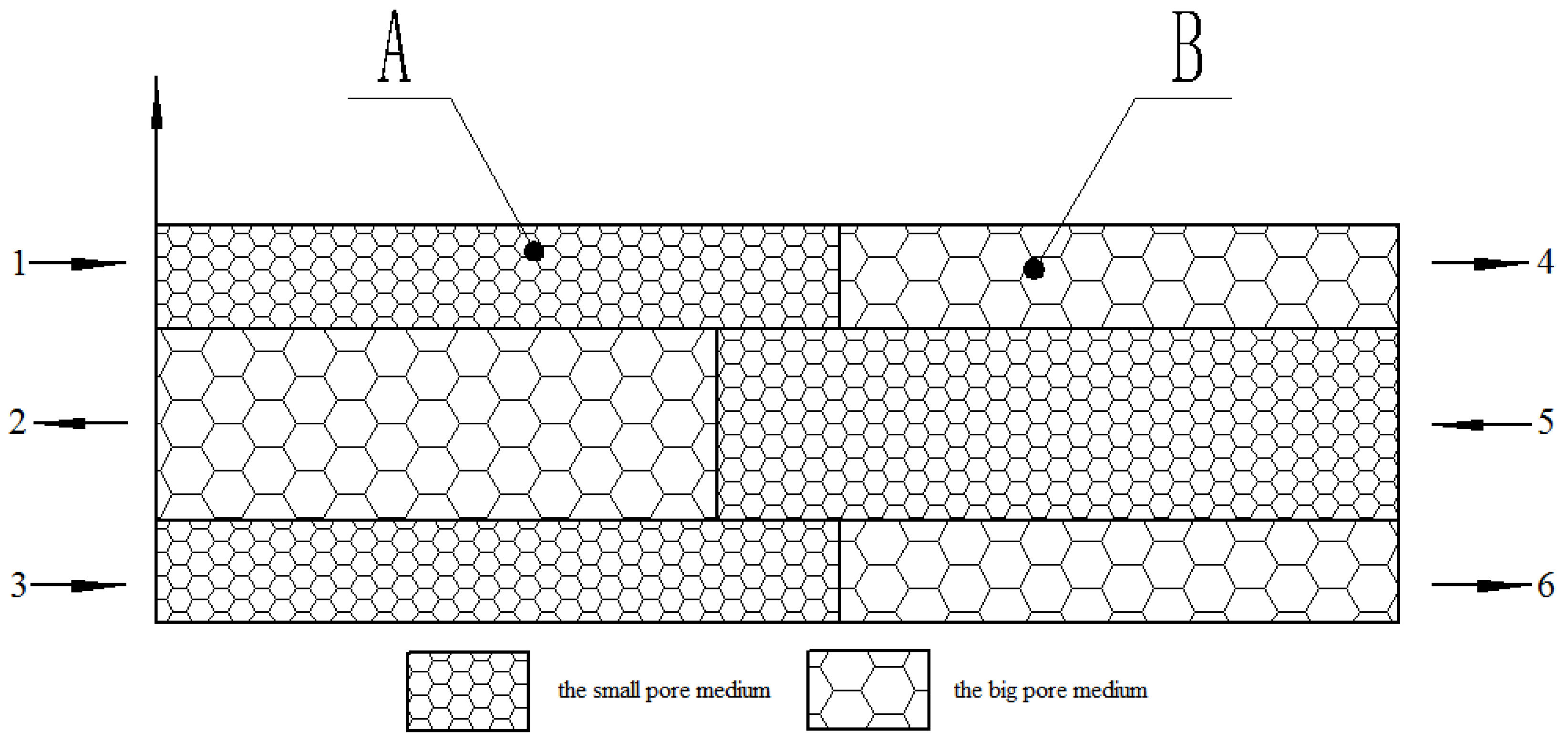
At present, burners with two-section structures have been widely used, as shown in Figure 1. This burner is composed of two porous media with different porosities. The smaller-pored medium is regarded as the preheating zone, and the other is the combustion zone. As illustrated in Figure 2, the new burner is divided into two sections: the preheating zone and the combustion zone. Our previous research suggested an optimal ratio of 1.2:1 for the burner. The exterior of the new burner is a cylinder with a 0.025 m radius and 0.22 m length. The lengths of the porous media of the preheating and combustion zones are 0.12 m and 0.1 m, respectively. The new burner consists of double decks, both of which are composed of two porous media with different porosities. The material is silicon carbide. The media with different pores of the inner and outer deck are staggered, and the small-pore medium is used as the preheating zone of the combustion; the other is the main combustion zone. The cross-sectional radius of the inner deck is 0.0125 m. The gases simultaneously enter into the preheating zone of the small-pore medium from two ends of the new burner. In addition to convection heating, the premixed gas can be heated by the solid heat conduction and heat radiation from the surrounding combustion zone with the big-pore medium. The heat reflux will further enhance the heat storage effect, and the combustion stability is thus improved. The contact area between the small-pore preheating zone and the big-pore combustion zone of the new burner is larger. Therefore, the fully premixed gas will be burned in a flow process, which completes the chemical reaction and releases energy. The equivalence ratio of premixed gas in the burner inlet was set to 0.65, the corresponding volume ratio of methane/air was 6%, the inlet flow velocity was 0.85 m/s, and the temperature of premixed gas was 300 K.
Meshing enables the discretization of the geometry into small units of simple shapes, referred to as mesh elements. Because the new burner has double decks of a nested type, the unstructured mesh can adapt to the structural requirements. The partition method was the T mesh and the element form was the regular tetrahedral element. Due to the obvious symmetry of the model, the axisymmetric model was adopted in the mesh. To ensure the accuracy of the calculation, the mesh spacing was 0.1 mm; finally, the mesh with 16,028 nodes was selected. According to the research theory [36], the reaction mechanism has little effect on the temperature distribution of porous medium burners. Therefore, a simple one-step reaction mechanism was adopted in the numerical model, namely,
CH4 + 2(O2 + 3.76N2) = CO2 + 2H2O + 7.52N2
3.2. Fundamentals
Because the structure of the porous medium burner is simple, the pores of the porous material are small, and the vortex is also small, it is assumed that the turbulence effect increases the flame front thickness and heat transfer and that the flame propagation is one-dimensional. The chemical source can be calculated by the Arrhenius formula. To simplify the calculation, the following assumptions were made:
①The gravity effect is ignored, and the gradient of each physical quantity is zero in the cross section of the circular cylinder.
②The porous medium is considered a homogeneous optical material and dispersion structure.
③The outer wall of the burner is adiabatic and nonslip, whereas the inner wall is set to have grey body radiation. The heat process between different parts is an unsteady-state process.
④Gas phase radiation is neglected.
⑤The potential high-temperature solid catalysis effect is ignored.
⑥The flame surface is at the coordinate origin of the X axis during steady combustion; the flame front is located near the interface of the two-deck porous medium.
⑦The premixed methane-air gas is regarded as an ideal gas.
Based on the above assumptions, the balance equations are as follows:
(1) Continuity equation:
where is the density of the premixed gas, is the porosity of the porous medium, and is the velocity vector.
(2) Momentum conservation equation:
where is the viscous resistance coefficient, is the inertia resistance coefficient, and is the permeability of the porous medium.
(3) Component conservation equation:
where is the mass fraction of the component, is the diffusion velocity, is the velocity with respect to a stationary coordinate system, is the molecular weight of the component, and is the molar formation rate of the component.
(4) Gas energy equation:
where is the heat efficiency of the chemical reaction, is the thermal conductivity of the premixed gas, is the volumetric convective heat transfer coefficient, is the molar enthalpy of formation of the component, is the specific heat capacity of the mixed gas at constant pressure, and is the gas phase temperature.
Because the gas content is low, the one-step chemical reaction mechanism of methane/air is used. The gas viscosity is significantly related to the temperature but is almost independent of the pressure. When the temperature is less than 2000 K, the gas viscosity can be calculated by the Sutherland formula.
(5) Solid state energy equation:
where is the effective heat transfer coefficient of the solid porous medium, is the effective thermal conductivity of the porous medium, and is the heat transfer coefficient; is the radiation attenuation coefficient of the porous medium, , and the coefficient m reduces with the increase in the average pore size of the porous medium, but increases with the increase in porosity. According to the porosity of the porous medium and the results of the experiment, m is 4, is the density of the porous medium, is the porous medium temperature, and is the heat capacity at constant pressure.
(6) State equation of ideal gas:
where W is the average molecular weight of the mixed gas, and R is the gas constant. Without consideration of the rich combustion condition, the single-step chemical reaction mechanism of methane/air is used.
(7) Determination of solid radiation parameters:
The radiation absorption coefficient of the foam ceramic material is 0.4 in the literature [34]. Based on the literature data, the radiation scattering rate of foam ceramics is defined as a function of porosity:
The radiation scattering rate can be calculated by the following formula [35]:
After conversion, it can be concluded that the calculation formulae of the scattering coefficient and absorption coefficient of the foam ceramic are as follows:
The mechanism of methane oxidation (GRI1.2) is used in the chemical reaction, which consists of 32 components and 177 basic elements; the mechanism has been verified by many scholars. The thermal physical properties of the porous media are assumed to be constant [37].
3.3. Boundary Condition
The energy and component conservation equations are boundary value problems, and the relevant boundary conditions are required for the solution. The inlet of the gas mixture was set as the velocity inlet, and the inlet temperature and ambient temperature of the premixed mixture were 300 K. The external wall heat loss includes two parts: heat transfer to the environment and thermal radiation. The specific settings are as follows:
At the burner outlet, there are large radiation heat losses; the outlet boundary condition for a given solid temperature is as follows:
where is the surface radiation coefficient of the porous medium.
3.4. Numerical Scheme
The equations were discretized and solved using Fluent software. When the energy equation of the porous medium is solved, only the single-temperature model can be used in the software. However, the high-temperature heat in the flame zone of a porous medium burner will be transferred to a solid medium. At the same time, the solid medium can accept the energy of convection, heat conduction, and heat radiation. Therefore, two energy equations need to be used. To ensure good convergence of the calculation results, sub-relaxation iteration was adopted. The residual error of the energy equation was set to 1.0 × 10⁻⁶, and the residual error of all other variables was set to 1.0 × 10⁻⁵. When the initialization was finished, the initial velocity of the whole flow field was set to the flow velocity of the premixed gas in the inlet, and steady-state iteration was carried out. When chemical reactions were calculated, to ensure the stability of the calculation results and accelerate the convergence, a high-temperature heat source for the ignition needed to be set up, so the temperature in the calculation area was initially set to 1600 K. The same setting also was found in the literature [28]. Eight turbulence models were set up in Fluent software according to the different situations of turbulent fluid flow. The standard k–ε model was used to simulate the combustion in this study. To obtain the characteristics of premixed gas combustion in a porous medium with different equivalence ratios, the equivalence ratios simulated were 0.85, 0.75, 0.45, and 0.35, with inlet flow velocities of 1.15 m/s, 1 m/s, 0.7 m/s and 0.55 m/s, respectively. Parameters of the porous medium burner are listed in Table 1.
4. Results and Discussion
4.1. Analysis of the Effect of the Premixed Gas Combustion
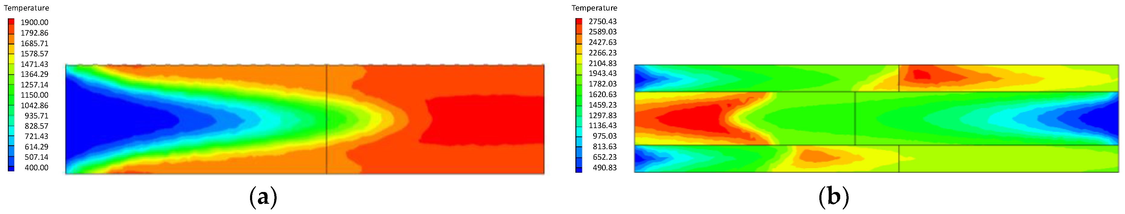
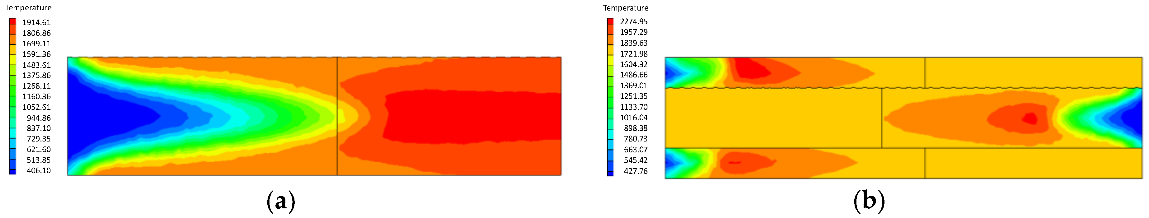
Figure 3 shows the stable temperature of the premixed gas combustion in the ordinary burner and the new burner when the equivalence ratio is 0.65 and inlet flow velocity is 0.85 m/s. In Figure 3a, the temperature change is not obvious in the small-pore-medium zone, indicating that the combustion has not been fully developed. A lot of the premixed gas is burned at the interface of the porous medium, and the stationary flame front is formed in the big-pore-medium zone. When the equivalence ratio is 0.65 and the flow velocity in the inlet is 0.85 m/s, the temperature peak value in the ordinary burner reaches about 1900 K, and the temperature in the outlet is about 1850 K; this result is consistent with previous work in the literature [19,20,21]. There is a difference between the results in this simulation and the literature; the reason for this difference is that a three-dimensional reaction model is used in this study, which is different from the two-dimensional model [21]. In addition, the simulation results are sensitive to the model.
Under the same conditions, the temperature peak of the new burner is up to approximately 2600 K, and the temperature in the outlet zone is higher than 2400 K. The temperature peak is higher than the corresponding maximum temperature of the ordinary burner, which indicates that premixed gas combustion in the new burner is carried out more thoroughly, and the heat storage and heat transfer capacity of the porous medium in the new burner can be better realized. In the ordinary burner, the temperature in the outlet zone is slightly lower than that in the inner zone. The porous medium with high temperature in the outlet transfers a part of heat upstream; therefore, the temperature in the outlet will decrease. Among the released heat from premixed gas combustion in the porous medium, a considerable part is from high-temperature radiation of the porous medium; the radiation heat can directly heat materials, and has high heat transfer efficiency.
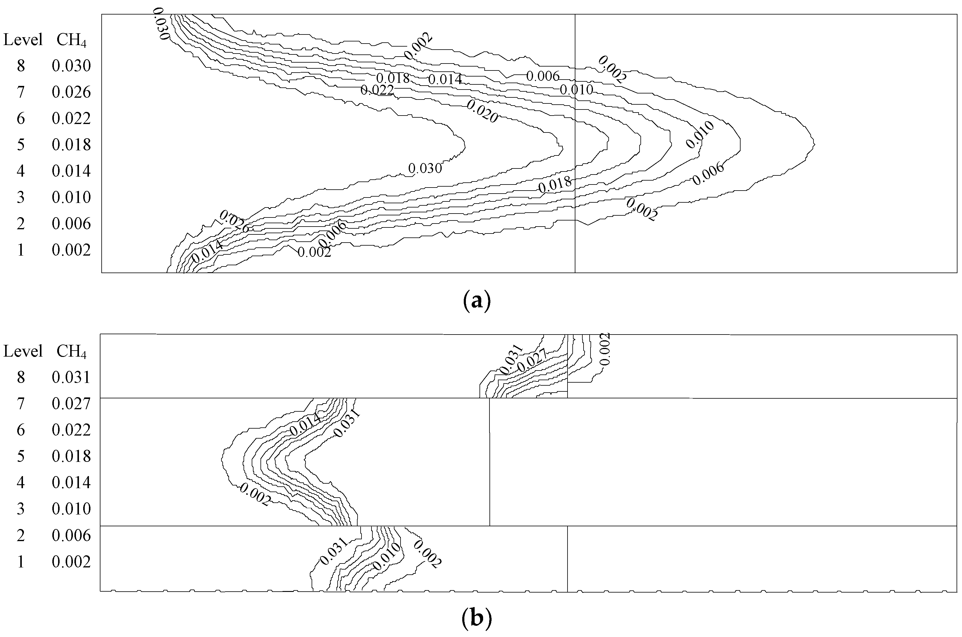
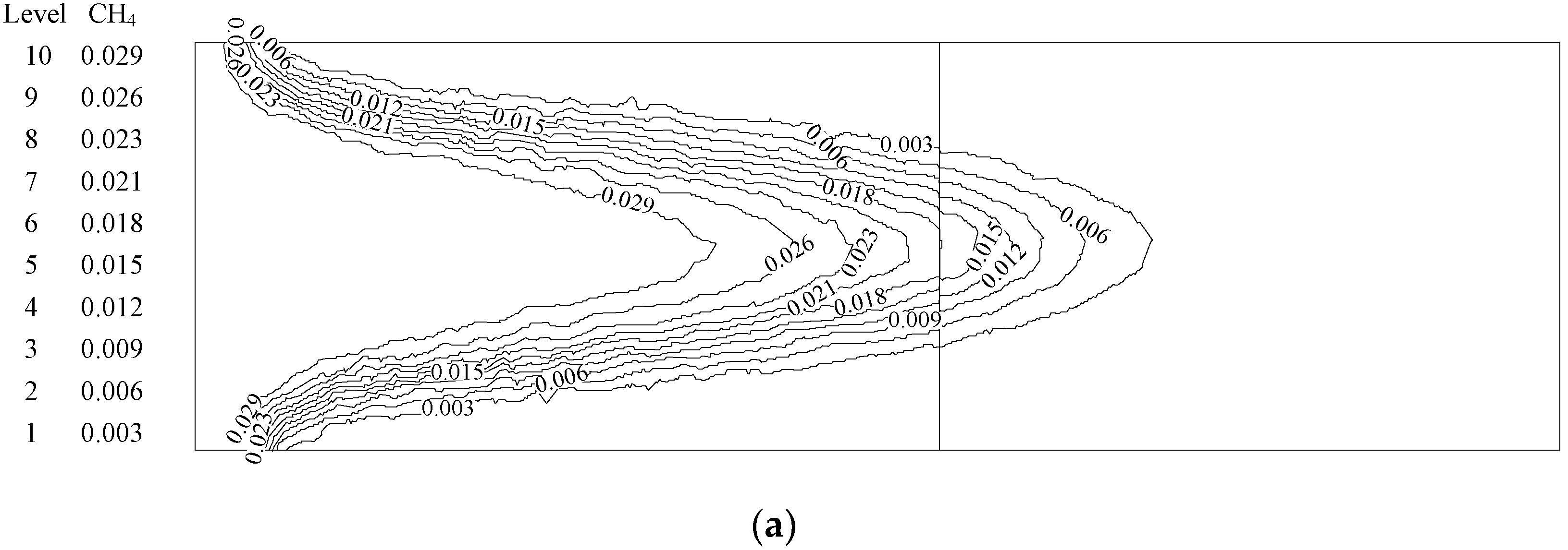
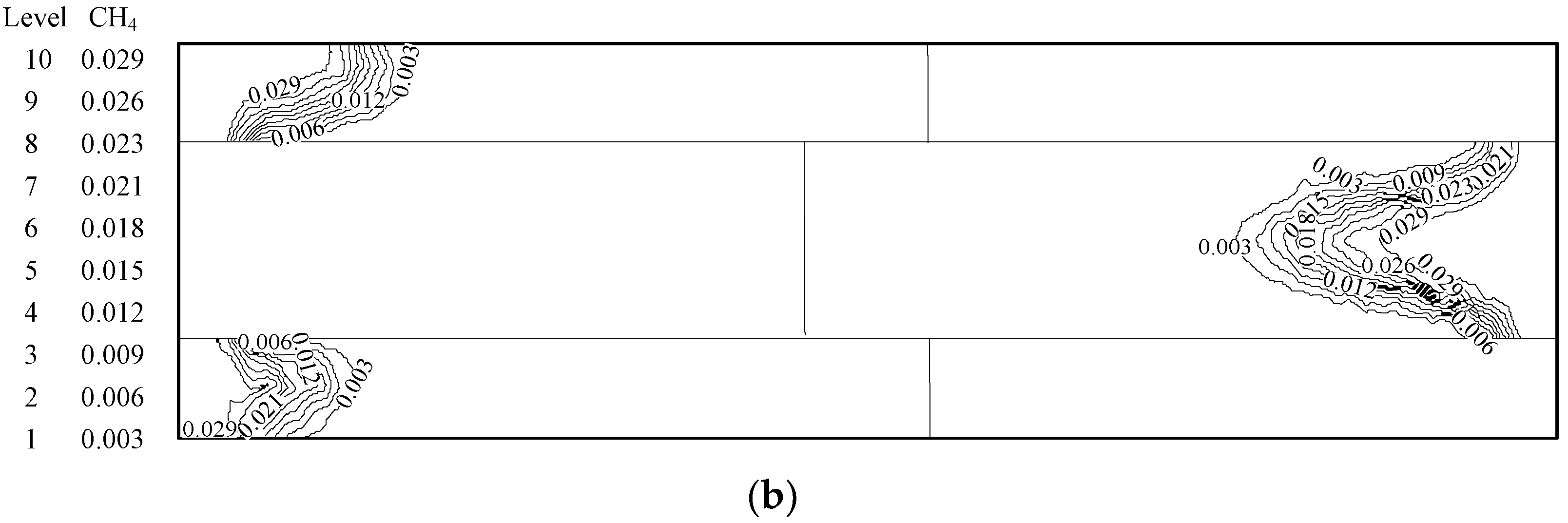
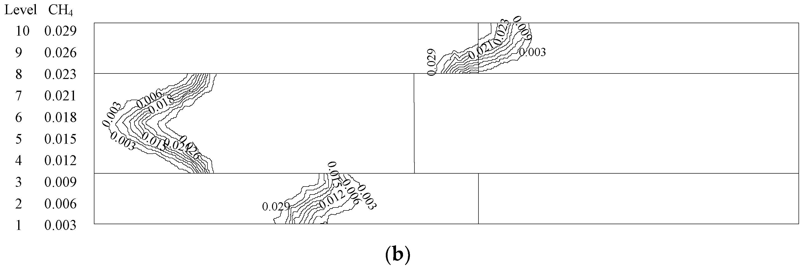
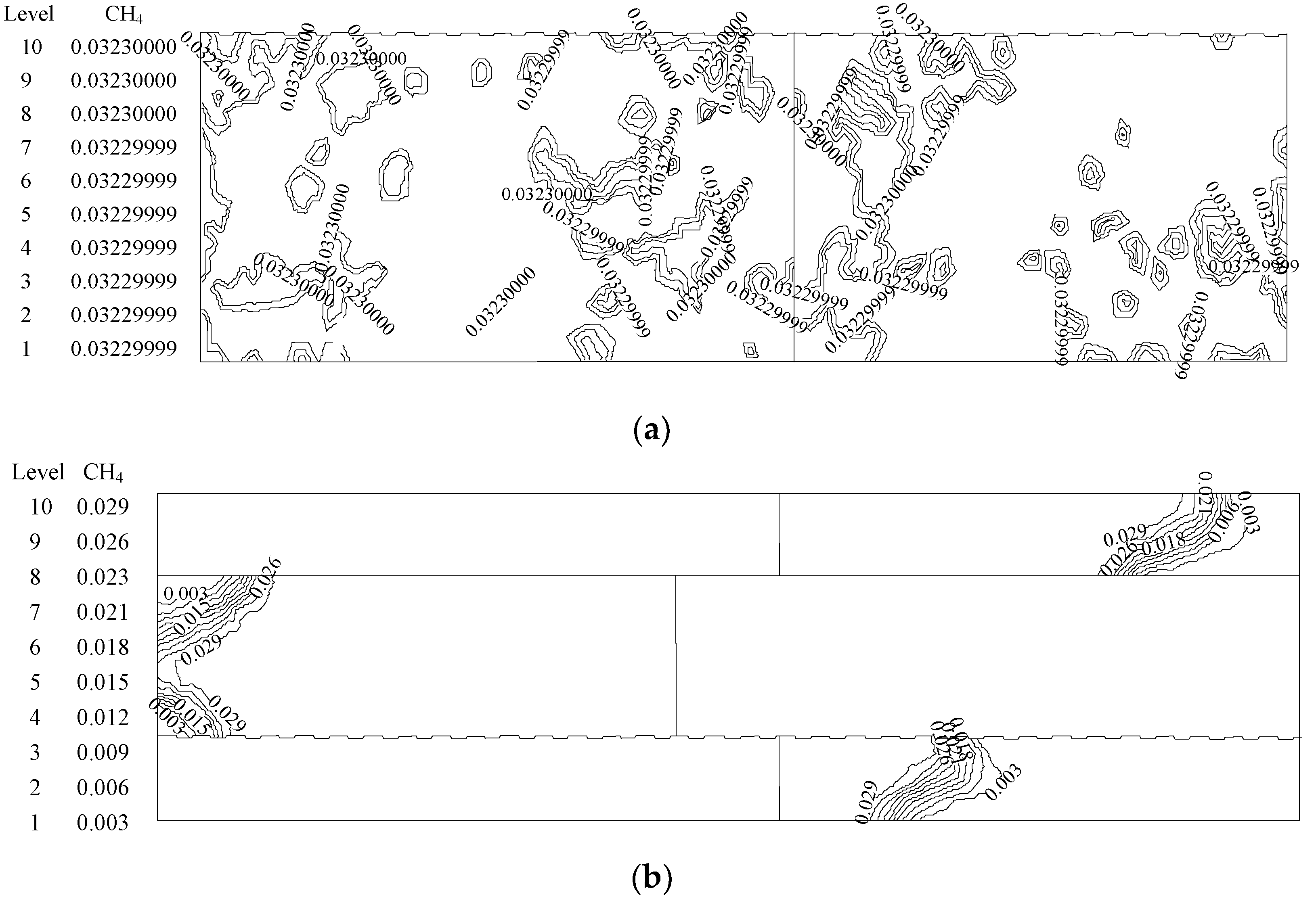
Figure 4 illustrates the gas concentration contours in the two kinds of burners after steady combustion. The gas mass fractions of the axis outlets in the two kinds of burners stabilize at 0.002. The advantages of premixed combustion in a porous medium are fully reflected; in consequence, the efficient use of gaseous fuels can be achieved using the new burner.
At a certain flow velocity, the new burner can obtain a higher combustion temperature and higher combustion efficiency, because the contact area between the preheating zone and the combustion zone is larger in the new burner. Thus, the heat transfer effect of the reverse heat reflux, heat conduction, and radiation heat in the combustion zone is more significant, and the reaction proceeds more fully.
4.1.1. Influence of the Equivalence Ratio of Premixed Gas on Combustion Degree
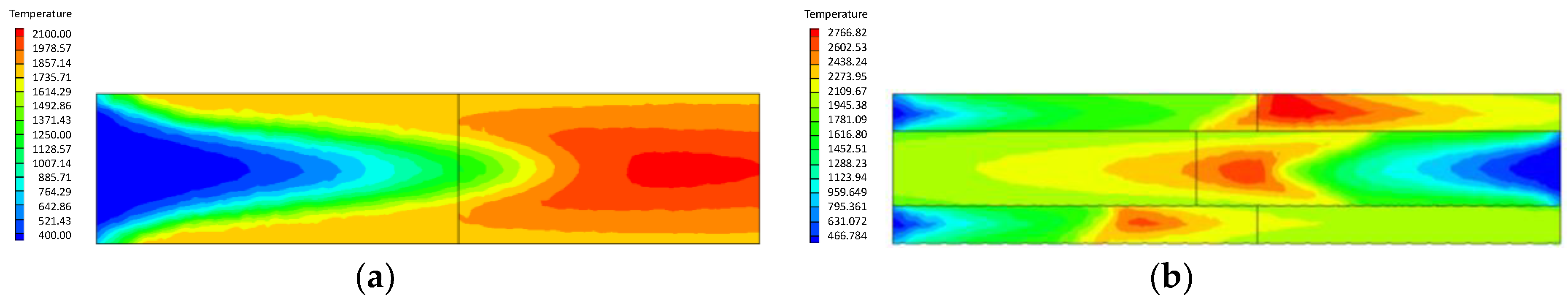
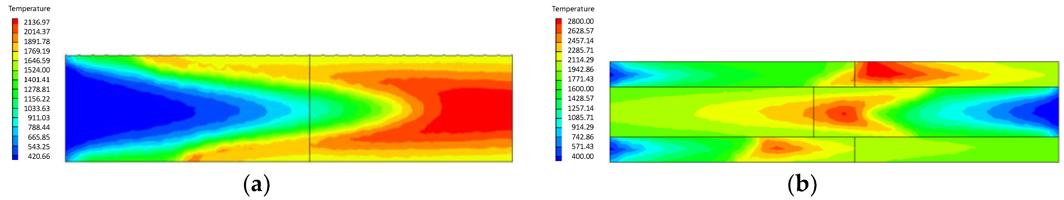
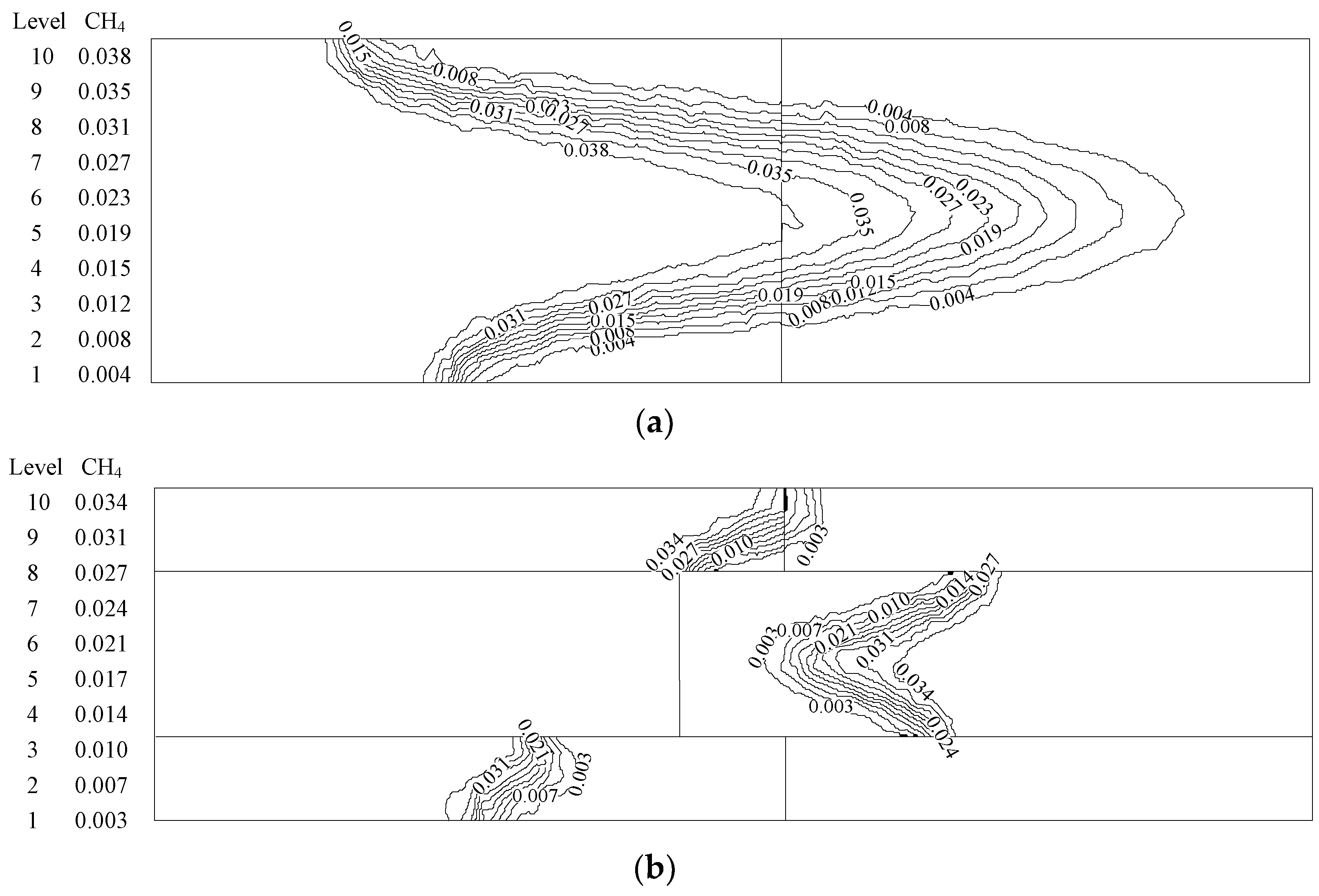
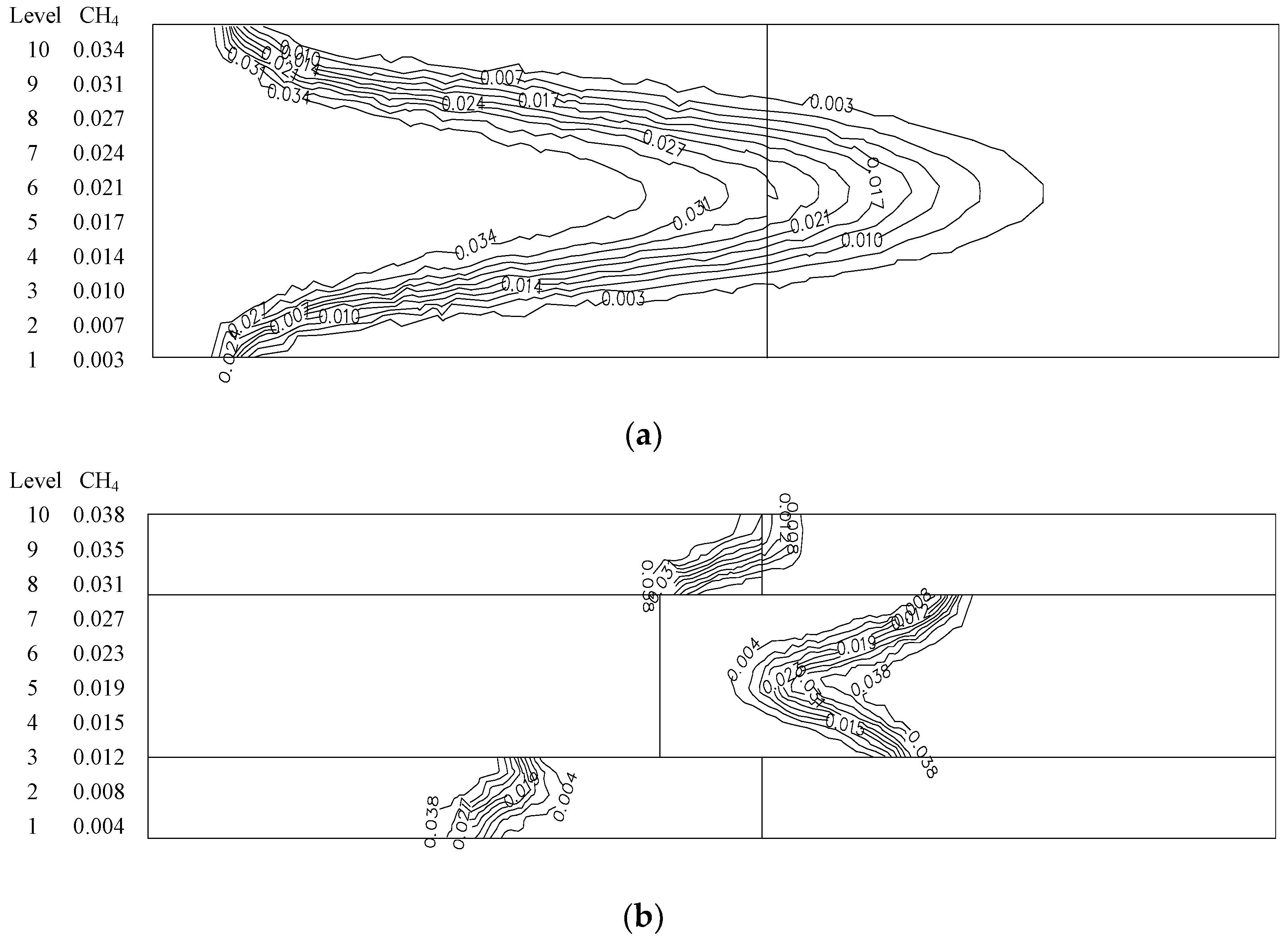
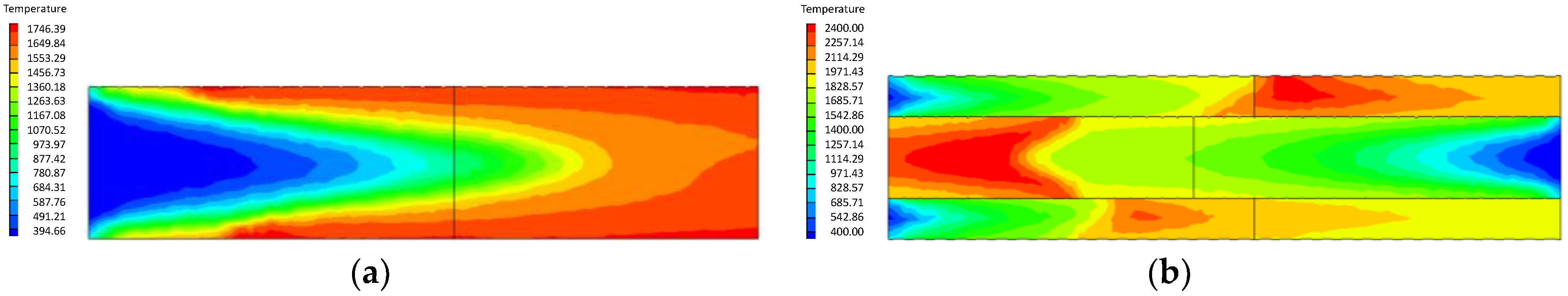
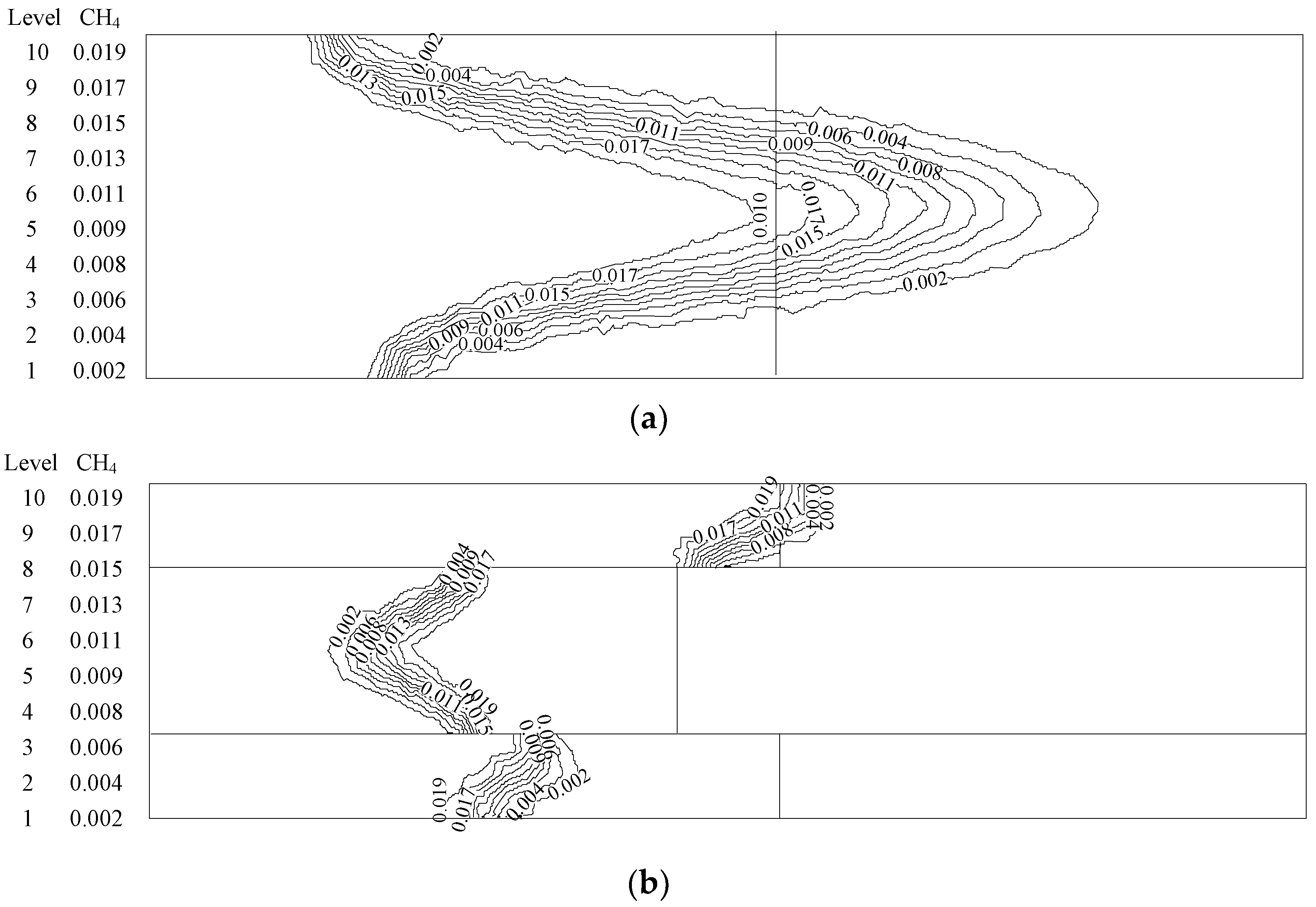
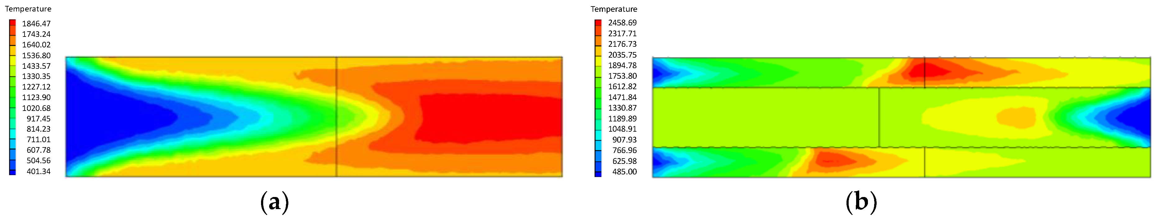
Gas concentration is often described using the concentration equivalence ratio. The greater the ratio, the higher the proportion of methane in the mixture. Figure 5 and Figure 6 show the temperature contours of gas mixtures with equivalence ratios of 0.75 and 0.85, respectively, during combustion in the ordinary and new burners. Figure 7 and Figure 8 illustrate the gas concentration contours correspondingly.
When the equivalence ratio is high and the excess air coefficient is small, it is hard to complete the combustion. Under these two equivalence ratios, the location of the flame surface and the gas mixture combustion consumption are similar. When the equivalence ratio is 0.85, the inner temperature of the new burner can reach 2700 K. However, the outlet temperature is not less than 2000 K, which is higher than the temperature peak in the ordinary burner under the same conditions. This shows that the combustion degree and the temperature in the new burner are higher, and the new burner’s advantage of saving energy is very obvious.
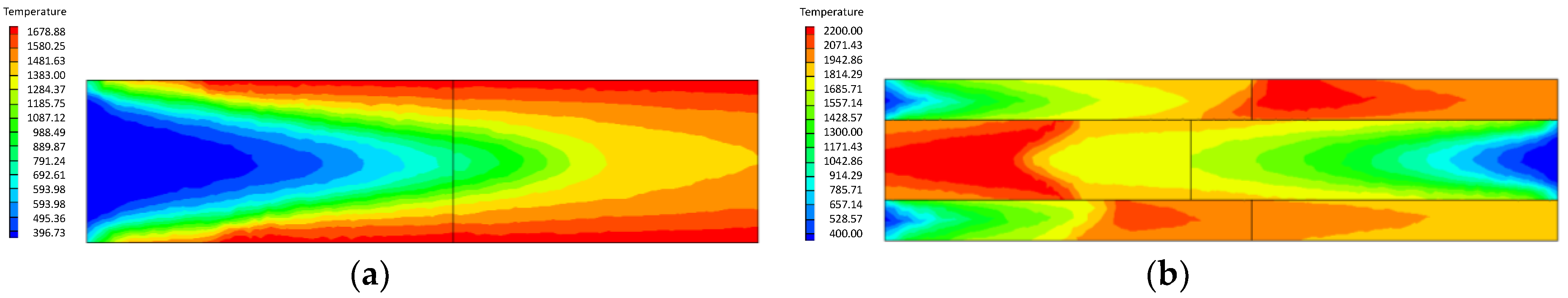
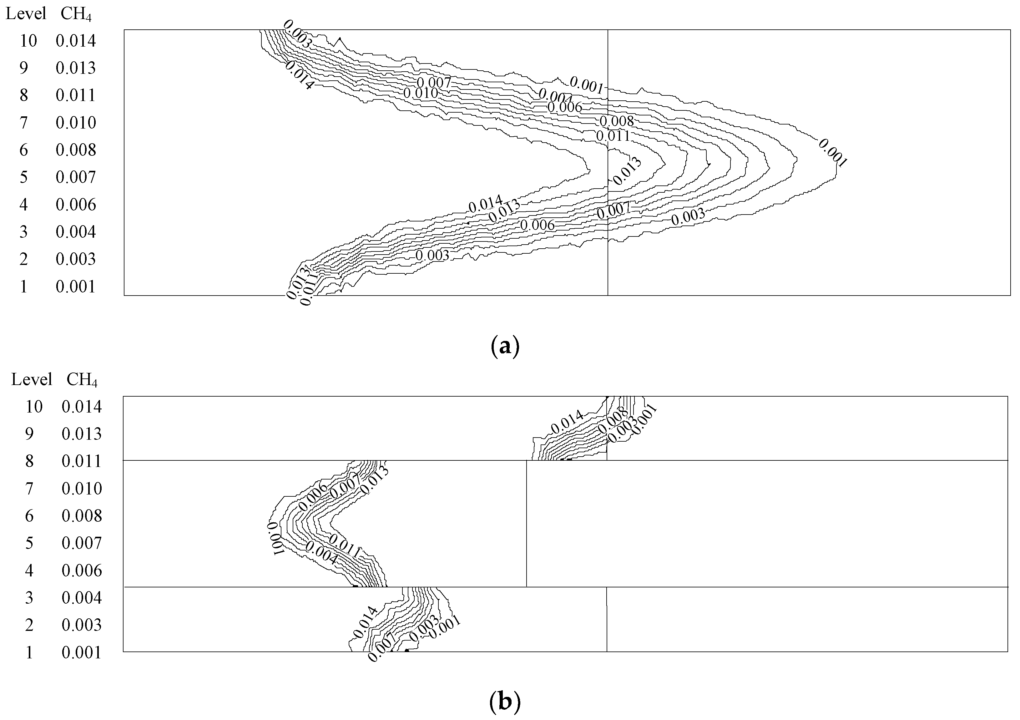
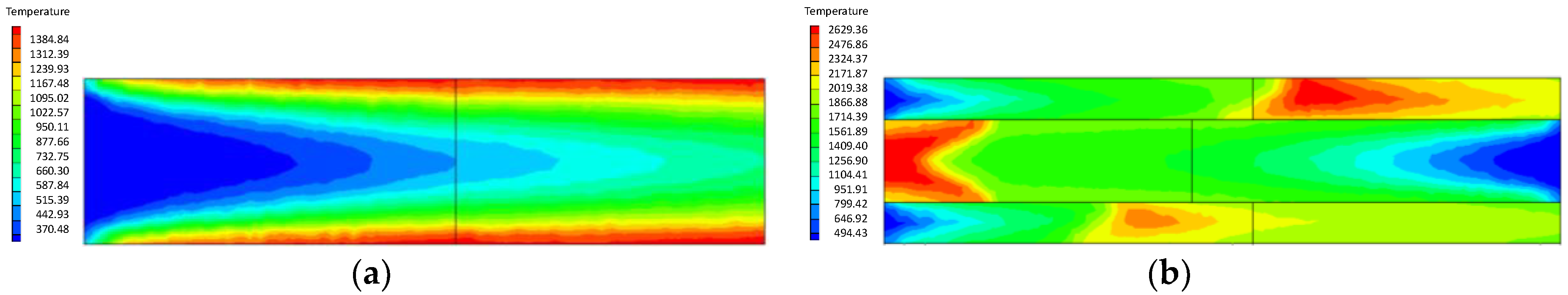
Figure 9 and Figure 10 show the temperature contours of gas mixture combustion in the two kinds of burners with equivalence ratios of 0.45 and 0.35. Figure 11 and Figure 12 are the gas concentration contours of gas mixture combustion in the two kinds of burners.
With the reduction of the equivalence ratio, the combustion flame is oriented towards the rear and becomes closer to the outlet position; this is reflected in both kinds of burners and is consistent with the laws from the literature [19,20,21,30]. The reliability of the simulation results is also proved. By making this comparison, it can be concluded that when low-concentration gas combustion is carried out in the ordinary burner, the combustion flame is oriented towards the rear and dispersed. At a low equivalence ratio, the outlet temperature of the new burner is not lower than 2000 K, and the temperature peak of the new burner is up to 2400 K (equivalence ratio 0.45) or 2200 K (equivalence ratio 0.35); the new burner not only has a higher temperature, but also has better stability of the flame surface.
4.1.2. Influence of the Inlet Flow Velocity of Premixed Gas on Combustion Intensity
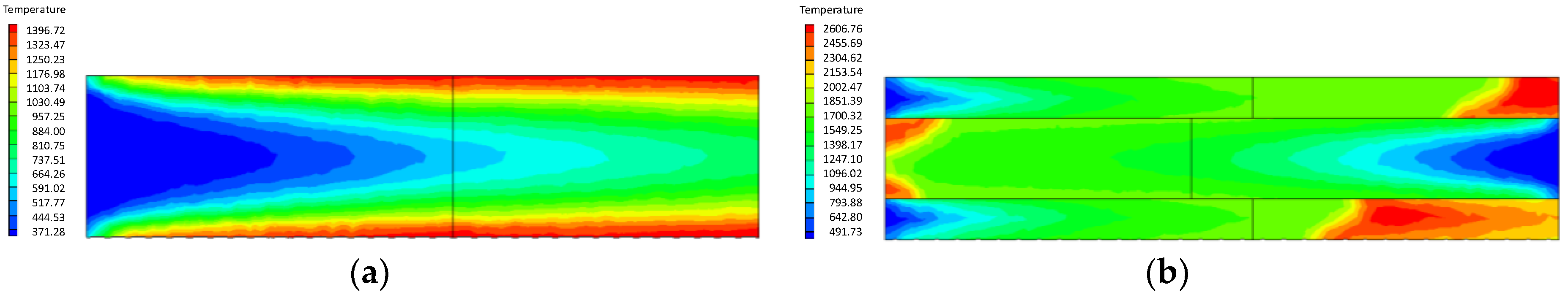
To analyze the inner temperature distribution of the burner and the gas temperature of the outlet at different mass flow velocities, the same equivalence ratio was set up to investigate the influence of the inlet flow velocity of premixed gas on the combustion state. Although the porous medium has the characteristics of high temperature resistance and corrosion resistance, the excessive temperature of the material may cause damage to the bearing capacity, affecting the working ability of the burner and threatening production. On the contrary, if the premixed gas temperature is too low, it is difficult to achieve effective heating for the material. Numerical simulation can predict the adjustment range of the inlet flow velocity of the new burner. According to the related literature [22], the combustion intensity should not be higher than 1500 kw/m2 (namely, when the equivalence ratio is 0.65, the corresponding inlet flow velocity is about 0.85 m/s), so the four flow velocities near to the flow velocity in the literature were calculated and compared. Figure 13, Figure 14, Figure 15 and Figure 16 are the inner temperature distributions of the two kinds of burners when the equivalence ratio is 0.65 and the inlet flow velocity is 0.65 m/s, 0.7 m/s, 0.95 m/s, or 1.15 m/s, respectively. Figure 17, Figure 18, Figure 19 and Figure 20 show the gas concentration contours of the two kinds of burners regarding these four flow velocities, respectively.
As can be seen from Figure 13, Figure 14, Figure 15 and Figure 16, the temperature in the vicinity of the burner inlet at low flow velocity is higher than that at high flow velocity. The combustion reaction begins earlier when the flow velocity is low. The main reason for this is that due to the low flow velocity, the contact time between the gas and the porous medium is prolonged, and the preheating effect is more durable. The temperature near the outlet of the burner is higher. The reason for this is that due to the complete reaction in the porous medium burner, the mass flow velocity of the premixed gas increases with the increase of the inlet flow velocity, i.e., the reaction amount of gas in unit time increases, which produces more heat. Figure 13, Figure 14, Figure 15 and Figure 16 show that the outlet temperature is 1800–2000 K, according to the high temperature resistance of the porous medium. This temperature range is acceptable for practical industrial applications. At the same time, at the velocity of 0.65~1.15 m/s, the temperature peak of the new burner is always higher than that of the ordinary burner.
When the inlet flow velocity of the premixed gas is less than the minimum flame propagation velocity, the flame will move toward the inlet and produce tempering, but premixed gas can be burned in the porous medium. If the inlet flow velocity of the premixed gas is more than the maximum flame propagation velocity, the flame will move toward the outlet and produce combustion extinguishment. In the flame stabilization zone, each equivalence ratio corresponds to a velocity range that can stabilize flame in the support layer. With the increase of the equivalence ratio, the flame stability zone increases. As the premixed gas has been effectively preheated, the flame propagation velocity is significantly improved. With the increase of the equivalence ratio, the flame stability zone becomes wider.
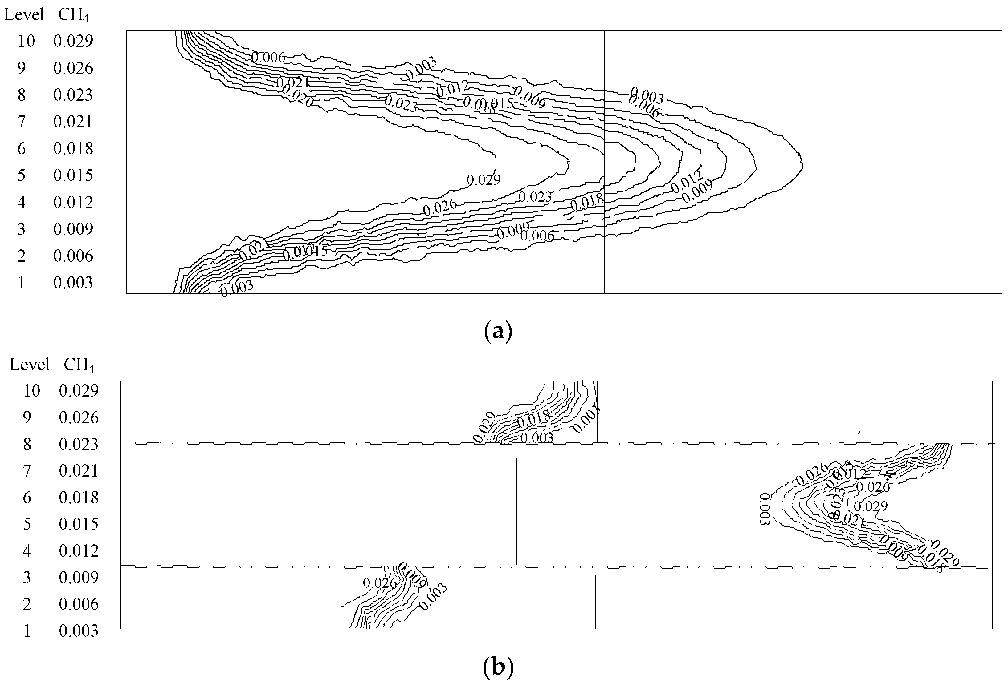
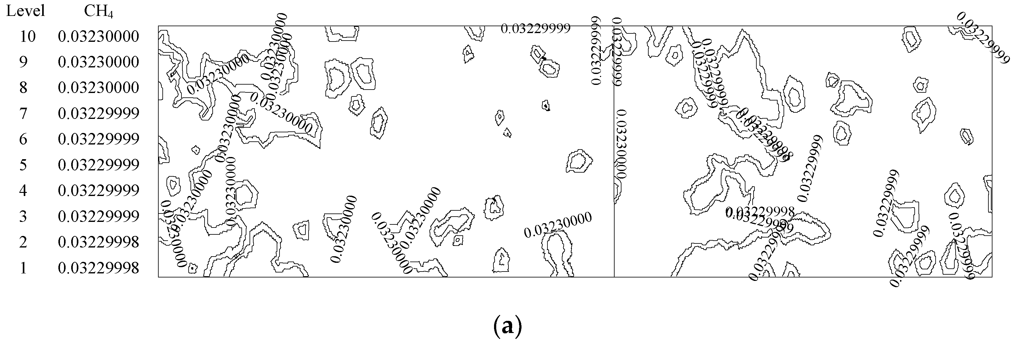
As can be seen from the Figure 17, Figure 18, Figure 19 and Figure 20, at the lower inlet flow velocity of the premixed gas, the premixed gas with the equivalence ratio of 0.65 can realize effective combustion in the two kinds of burners, and the combustion consumption degree is similar. When the inlet flow velocity reaches 0.95 m/s and 1.15 m/s, the temperature cloud figure and gas concentration contour show that gas combustion is not effective in the ordinary burner (the concentration experiences almost no change); however, in the new burner, the high-temperature flame moves toward the rear with the increase in premixed gas mass flow, the temperature peak is maintained over 2500 K, the attenuation of the gas concentration gradient is normal, and the combustion state is good.
4.2. NOXEmission Characteristics of Different Equivalence Ratios in the New Burner
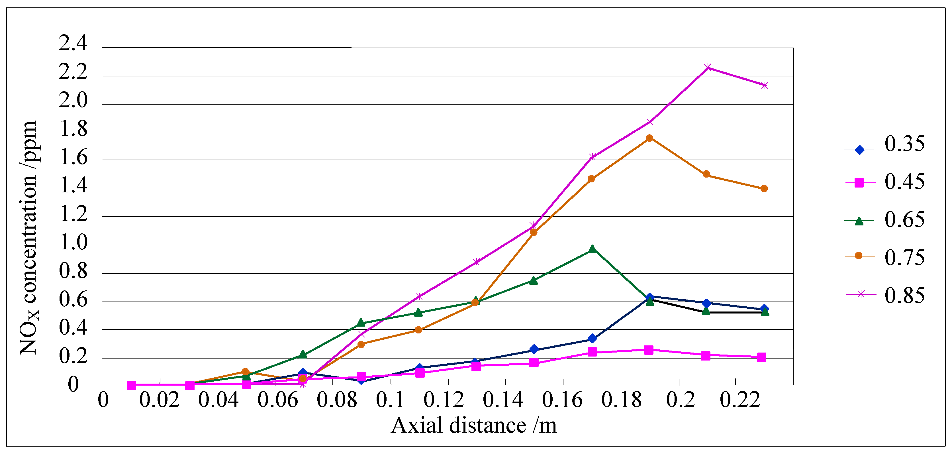
When the combustion reaction occurs, the nitrogen in the air/fuel is heated and decomposed under the oxidizing conditions of combustion, and toxic nitrogen oxides are then produced. Its compositions are mainly NO and NO2, which are collectively called NOx. The harm from emission of NOx cannot be ignored, and many countries have strict regulations concerning their emissions [38]. For this portion of the study, the flow velocity of the premixed gas in the new burner was fixed at 0.65m/s. Figure 21 is the schematic diagram of NOx emission, which depicts the NOx emission states under equivalence ratios of 0.35, 0.45, 0.65, 0.75, and 0.85, respectively.
As can be seen from Figure 21, in the porous medium combustion, the emission of pollutant NOx is very low. When the equivalence ratio of premixed gas is 0.65 and inlet flow velocity is 0.85 m/s, the NOx concentration in the new burner outlet is only 1 ppm approximately. When the equivalence ratio is 0.85, the highest concentration of NOx in the ordinary burner is about 2.3 ppm. Because NOx has a strong dependence on temperature, with the increase of mass flow velocity of the premixed gas, the combustion temperature becomes higher and higher, and the NOx emission consequently shows a trend of increase.
The NOx emission for an equivalence ratio of 0.45 is lower than that for an equivalence ratio of 0.35, which shows that NOx emission will decrease with the increase in the complete reaction degree(the emission concentration is lower than the minimum standard (100 ppm) in Beijing, China). However, the total emission amount of NOx will show an upward trend with the increase in the equivalence ratio. The reason for this is that with the increase in the equivalence ratio, the mass flow velocity of the combustible gas increases, the incomplete reaction degree increases, the combustion temperature is higher, and the NOx relatively increases. However, the emission is still lower than that from free combustion.
5. Conclusions
Based on the combustion mechanism of methane-air premixed gas in a porous medium, a new burner was proposed. A mathematical model for the premixed gas combustion in porous medium was established. The combustion performance for different equivalence ratios and premixed gas velocities in inlets was simulated. The methane combustion degree and distribution of temperature and pressure in the porous medium were analyzed. In addition, the concentrations of NOx emission for different equivalence ratios were studied. The following results were obtained:
- (1)
- Compared with the ordinary porous medium burner, the new burner can gather heat more effectively, thereby promoting gas combustion. As a result, the gas temperature in the new burner is much higher than that in the ordinary one.
- (2)
- At higher flow velocity, the short preheating time results in poor reaction of the premixed gas in the porous medium of the ordinary burner. On the contrary, under the condition of high flow velocity, the gas concentration contour gradually fades along the gas flow direction in the new burner. The combustion state is good, and the combustion heat is large.
- (3)
- The change of flow velocity of the premixed gas in the inlet exerts an important influence on the combustion in the porous medium. In the case of low flow velocity, the temperature in the inlet increases significantly. In contrast, the temperature in the outlet increases dramatically in the case of high flow velocity. The inlet flow velocity should be set within a reasonable range to ensure the safety and normal operation of the burner.
- (4)
- The emission concentration of major pollutants (NOX) from the new burner is much lower than the minimum standard ((100 ppm) in Beijing, China).
- (5)
- The radiation attenuation coefficient of the small-pore medium in the new burner increases, but the radiation attenuation coefficient of the big-pore medium in the new burner remains unchanged, which increases the stable operating range of the burner.
- (6)
- The thermal conductivity coefficient of the small-pore medium in the new burner increases, but the thermal conductivity coefficient of the big-pore medium in the new burner remains unchanged or reduces slightly, which increases the temperature peak and the stable operating range. The aperture of the porous medium should not be too large. A reasonable range of aperture size can maintain the stability of flame front and obtain the ideal temperature.
- (7)
- Compared with the traditional burner, the new porous medium burner has advantages in improving combustion efficiency, expanding flammability limits, and improving environmental friendliness. Therefore, the application prospects of the new porous medium burner are very broad. The influences of various factors on the combustion process of the new porous medium burner were simulated by CFD (computational fluid dynamics) and the basic characteristics were mastered. The numerical results can provide a theoretical basis and data support for the design of the new porous medium burner. If the design and manufacturing process of the new porous medium burner can be further strengthened, better application value will surely be attained.
Author Contributions
All the authors designed research, performed research, analyzed data, wrote and revised the paper, all authors contributed equally.
Funding
This research was funded by the National Natural Science Foundation Project of China, grant number (51704111, 51374003, 51774135 and 51604110).
Conflicts of Interest
The authors declare no conflicts of interest.
References
- Zhang, Y.; Lu, C.; Li, T. A Practical Countercurrent Fluid Catalytic Cracking Regenerator Model for in Situ Operation Optimization. AICHE J. 2012, 58, 2810–2819. [Google Scholar] [CrossRef]
- Jia, Z.; Feng, T. Gas Explosion Characteristics and Its Control Measures in Closed Fire Zone. Comput. Modell. New Technol. 2014, 18, 21–25. [Google Scholar]
- Kamal, M.M.; Mohamad, A.A. Combustion in Porous Media. Proc. Inst. Mech. Eng. Part A J. Power Energy 2006, 220, 487–508. [Google Scholar] [CrossRef]
- Valerio, G.; Rajnish, N.S.; Robert, R.R. Premixed Combustion of Methane-Air Mixture Stabilized over Porous Medium: A 2-D Numerical Study. Chem. Eng. Sci 2016, 152, 591–605. [Google Scholar]
- Mujeebu, M.A.; Abdullah, M.Z.; Bakar, M.A.; Mohamad, A.A.; Abdullah, M.K. Applications of Porous Media Combustion Technology Review. Appl. Energy 2009, 86, 1365–1375. [Google Scholar] [CrossRef]
- Wood, S.; Harris, A.T. Porous Burners for Lean-Burn Applications. Prog. Energy Combust. Sci. 2008, 34, 667–684. [Google Scholar] [CrossRef]
- Slimane, R.B.; Lau, F.S.; Khinkis, M.; Bingue, J.P.; Saveliev, A.V.; Kennedy, L.A. Conversion of Hydrogen Sulphide to Hydrogen by Super Adiabatic Partial Oxidation: Thermodynamic Consideration. Int. J. Hydrogen Energy 2004, 29, 1471–1477. [Google Scholar] [CrossRef]
- Min, D.K.; Shin, E.D. Laminar Premixed Flame Stabilized inside a Honeycomb Ceramic. Int. J. Heat Mass Transf. 1991, 34, 341–356. [Google Scholar]
- Hayashi, T.C.; Malico, I.; Pereira, J.C.F. Three-dimensional Modeling of Two-Layer Porous Burner for Household Application. Comput. Struct. 2004, 82, 1543–1550. [Google Scholar] [CrossRef]
- Kotani, Y.; Takeno, T. An Experimental Study of Stability and Combustion Characteristics of an Excess Enthalpy Flame. Symp. (Int.) Combust. 1982, 19, 1503–1509. [Google Scholar] [CrossRef]
- Pereira, F.M.; Oliveira, A.A.M. Analysis of the Combustion with Excess Enthalpy in Porous Media. In Proceeding of the European Combustion Meeting, Orléans, France, 2003; pp. 388–392. [Google Scholar]
- Mital, R.; Gore, J.P.; Viskanta, R. A Study of the Structure of Submerged Reaction Zones in Porous Ceramics Radiant Burners. Combust. Flame 1997, 111, 175–184. [Google Scholar] [CrossRef]
- Sathe, S.B.; Kulkarni, M.R.; Peck, R.E.; Tong, T.W. An Experimental and Theoretical Study of Porous Radiant Burner Performance. Symp. (Int.) Combust. 1990, 23, 1011–1018. [Google Scholar] [CrossRef]
- Chen, Y.K.; Matthews, R.D.; Howell, J.R. The Effect of Radiation on the Structure of Premixed Flame within a Highly Porous Inert Medium; American Society of Mechanical Engineers, Heat Transfer Division, (Publication) HTD: Boston, MA, USA, 1987; pp. 35–41. [Google Scholar]
- Wang, E.; Chen, L.; Wu, J. Application and Existing Problems of Porous Ceramics in the Combustion Field. Foshan Ceram. 2005, 100, 35–39. [Google Scholar]
- Chu, J. Study and Development of a Gradually-varied Porous Media Burner. Master’s Thesis, Zhejiang University, Hangzhou, China, 2005. [Google Scholar]
- Du, L.; Xie, M. Numerical Investigation on Effects of Porous Media in Premixed Combustion. J. Dalian Univ. Technol. 2004, 1, 70–75. [Google Scholar]
- Du, L. Investigation on Super-adiabatic Combustion of Lean Premixed Gases in Porous Media. Ph.D. Thesis, Dalian University of Technology, Dalian, China, 2003. [Google Scholar]
- Liu, H. Experimental Study and Numerical Simulation of Premixed Gas Combustion in Porous Media. Ph.D. Thesis, Northeastern University, Shengyang, China, 2010. [Google Scholar]
- Liu, H.; Dong, S.; Xing, N.; Li, B. Numerical Simulation of the Influence of Porous Medium Characteristics on Combustion Temperature and Pressure. Appl. Energy Technol. 2009, 10, 31–37. [Google Scholar]
- Barra, A.J.; Diepvens, G.; Ellzey, J.L.; Henneke, M.R. Numerical Study of the Effects of Material Properties on Flame Stabilization in a Porous Burner. Combust. Flame 2003, 134, 369–379. [Google Scholar] [CrossRef]
- Wang, H. Industrial Application and Numerical Simulation of Premixed Gas Combustion in Porous Media. Master’s Thesis, Northeastern University, Shengyang, China, 2009. [Google Scholar]
- Lee, D.K.; Noh, D.S. Experimental and Theoretical Study of Excess Enthalpy Flames Stabilized in a Radial Multi-Channel as a Model Cylindrical Porous Medium Burner. Combust. Flame 2016, 170, 79–90. [Google Scholar] [CrossRef]
- Mendes, M.A.A.; Pereira, J.M.C.; Pereira, J.C.F. A Numerical Study of the Stability of One-Dimensional Laminar Premixed Flame in Inert Porous Media. Combust. Flame 2008, 153, 525–539. [Google Scholar] [CrossRef]
- Afsharvahid, S.; Ashman, P.J.; Dally, B.B. Investigation of NOx Conversion Characteristics in a Porous Medium. Combust. Flame 2008, 152, 604–615. [Google Scholar] [CrossRef]
- Zhao, P. Study on Premixed Combustion in Inert Porous Media. Ph.D. Thesis, University of Science and Technology of China, Hefei, China, 2007. [Google Scholar]
- Huang, R. Combustion Characteristics of Multi-Species Low Calorific Gaseous Fuels in a Two-Layer Porous Burner. Master’s Thesis, Zhejiang University, Hangzhou, China, 2016. [Google Scholar]
- Dong, S. Preliminary Experimental and Numerical Study of Premixed Combustion in Porous Inert Media. Master’s Thesis, Northeastern University, Shengyang, China, 2008. [Google Scholar]
- Zheng, Z. Numerical Study of Natural Gas Premixed Combustion in Porous Inert Media. Master’s Thesis, Shanghai Jiaotong University, Shanghai, China, 2007. [Google Scholar]
- Jia, Z.; Lin, B.; Ye, Q. Analysis of Influencing Factors and Flame Acceleration Mechanism of Gas Explosion Propagation in Tube. Min. Eng. Res. 2009, 24, 57–62. [Google Scholar]
- Gao, Z.; Cui, G.; Zuo, D. Discussion on the Reaction Mechanism of Carbon Combustion. J. Shandong Polytech. Univ. 2002, 16, 39–42. [Google Scholar]
- Yang, S.; Tao, W. Heat Transfer, 3rd ed.; Higher Education Press: Beijing, China, 1998. [Google Scholar]
- Han, Z. Fuel and Combustion; Metallurgical Industry Press: Beijing, China, 2007. [Google Scholar]
- Wang, P. Theoretical and Experimental Study on Gas Thermal Counter Current Oxidation of Low Concentration Methane in Coal Mine. Ph.D. Thesis, Central South University, Changsha, China, 2012. [Google Scholar]
- Dhamrat, R.S.; Ellzey, J.L. Numerical and Experimental Study of the Conversion of Methane to Hydrogen in a Porous Media Reactor. Combust. Flame 2006, 144, 698–709. [Google Scholar] [CrossRef]
- Mohammadi, I.; Hossainpour, S. The Effects of Chemical Kinetics and Wall Temperature Performance of Porous Media Burners. Heat Mass Transf. 2013, 49, 869–877. [Google Scholar] [CrossRef]
- Younis, L.B.; Viskanta, R. Experimental Determination of the Volumetric Heat Transfer Coefficient between Stream of Air and Ceramic Foam. Int. J. Heat Mass Transf. 1993, 36, 1425–1434. [Google Scholar] [CrossRef]
- Li, Z.; Cheng, Y. Fire Engineering; China University of Mining and Technology Press: Xuzhou, China, 2002. [Google Scholar]
Figure 1.
The ordinary burner.

Figure 2.
Sectional view of the physical model of the new burner. 1, premixed gas inlet; 2, exhaust gas outlet; 3, premixed gas inlet; 4, exhaust gas outlet; 5, premixed gas inlet; 6, exhaust gas outlet.
Figure 2.
Sectional view of the physical model of the new burner. 1, premixed gas inlet; 2, exhaust gas outlet; 3, premixed gas inlet; 4, exhaust gas outlet; 5, premixed gas inlet; 6, exhaust gas outlet.

Figure 3.
Temperature contours in the ordinary burner and the new burner when the equivalence ratio is 0.65 and the inlet flow velocity is 0.85 m/s. (a) Temperature contours in the ordinary burner; (b) Temperature contours in the new burner.
Figure 3.
Temperature contours in the ordinary burner and the new burner when the equivalence ratio is 0.65 and the inlet flow velocity is 0.85 m/s. (a) Temperature contours in the ordinary burner; (b) Temperature contours in the new burner.

Figure 4.
CH4 concentration contours in the ordinary burner and the new burner when the equivalence ratio is 0.65 and the inlet flow velocity is 0.85m/s. (a) CH4 concentration contours in the ordinary burner; (b) CH4 concentration contours in the new burner.
Figure 4.
CH4 concentration contours in the ordinary burner and the new burner when the equivalence ratio is 0.65 and the inlet flow velocity is 0.85m/s. (a) CH4 concentration contours in the ordinary burner; (b) CH4 concentration contours in the new burner.

Figure 5.
Temperature contours in the ordinary burner and the new burner when the equivalence ratio is 0.75 and the inlet flow velocity is 0.85 m/s. (a) Temperature contours in the ordinary burner; (b) Temperature contours in the new burner.
Figure 5.
Temperature contours in the ordinary burner and the new burner when the equivalence ratio is 0.75 and the inlet flow velocity is 0.85 m/s. (a) Temperature contours in the ordinary burner; (b) Temperature contours in the new burner.

Figure 6.
Temperature contours in the ordinary burner and the new burner when the equivalence ratio is 0.85 and the inlet flow velocity is 0.85 m/s. (a) Temperature contours in the ordinary burner; (b) Temperature contours in the new burner.
Figure 6.
Temperature contours in the ordinary burner and the new burner when the equivalence ratio is 0.85 and the inlet flow velocity is 0.85 m/s. (a) Temperature contours in the ordinary burner; (b) Temperature contours in the new burner.

Figure 7.
CH4 concentration contours in the ordinary burner and the new burner when the equivalence ratio is 0.75 and the inlet flow velocity is 0.85 m/s. (a) CH4 concentration contours in the ordinary burner; (b) CH4 concentration contours in the new burner.
Figure 7.
CH4 concentration contours in the ordinary burner and the new burner when the equivalence ratio is 0.75 and the inlet flow velocity is 0.85 m/s. (a) CH4 concentration contours in the ordinary burner; (b) CH4 concentration contours in the new burner.

Figure 8.
CH4 concentration contours in the ordinary burner and the new burner when the equivalence ratio is 0.85 and the inlet flow velocity is 0.85 m/s. (a) CH4 concentration contours in the ordinary burner; (b) CH4 concentration contours in the new burner.
Figure 8.
CH4 concentration contours in the ordinary burner and the new burner when the equivalence ratio is 0.85 and the inlet flow velocity is 0.85 m/s. (a) CH4 concentration contours in the ordinary burner; (b) CH4 concentration contours in the new burner.

Figure 9.
Temperature contours in the ordinary burner and the new burner when the equivalence ratio is 0.45 and the inlet flow velocity is 0.85 m/s. (a) Temperature contours in the ordinary burner; (b) Temperature contours in the new burner.
Figure 9.
Temperature contours in the ordinary burner and the new burner when the equivalence ratio is 0.45 and the inlet flow velocity is 0.85 m/s. (a) Temperature contours in the ordinary burner; (b) Temperature contours in the new burner.

Figure 10.
Temperature contours in the ordinary burner and the new burner when the equivalence ratio is 0.35 and the inlet flow velocity is 0.85 m/s. (a) Temperature contours in the ordinary burner; (b) Temperature contours in the new burner.
Figure 10.
Temperature contours in the ordinary burner and the new burner when the equivalence ratio is 0.35 and the inlet flow velocity is 0.85 m/s. (a) Temperature contours in the ordinary burner; (b) Temperature contours in the new burner.

Figure 11.
CH4 concentration contours in the ordinary burner and the new burner when the equivalence ratio is 0.45 and the inlet flow velocity is 0.85 m/s. (a) CH4 concentration contours in the ordinary burner; (b) CH4 concentration contours in the new burner.
Figure 11.
CH4 concentration contours in the ordinary burner and the new burner when the equivalence ratio is 0.45 and the inlet flow velocity is 0.85 m/s. (a) CH4 concentration contours in the ordinary burner; (b) CH4 concentration contours in the new burner.

Figure 12.
CH4 concentration contours in the ordinary burner and the new burner when the equivalence ratio is 0.35 and the inlet flow velocity is 0.85 m/s. (a) CH4 concentration contours in the ordinary burner; (b) CH4 concentration contours in the new burner.
Figure 12.
CH4 concentration contours in the ordinary burner and the new burner when the equivalence ratio is 0.35 and the inlet flow velocity is 0.85 m/s. (a) CH4 concentration contours in the ordinary burner; (b) CH4 concentration contours in the new burner.

Figure 13.
Temperature contours in the ordinary burner and the new burner when the equivalence ratio is 0.65 and the inlet flow velocity is 0.65 m/s. (a) Temperature contours in the ordinary burner; (b) Temperature contours within the new burner.
Figure 13.
Temperature contours in the ordinary burner and the new burner when the equivalence ratio is 0.65 and the inlet flow velocity is 0.65 m/s. (a) Temperature contours in the ordinary burner; (b) Temperature contours within the new burner.

Figure 14.
Temperature contours in the ordinary burner and the new burner when the equivalence ratio is 0.65 and the inlet flow velocity is 0.7 m/s. (a) Temperature contours in the ordinary burner; (b) Temperature contours in the new burner.
Figure 14.
Temperature contours in the ordinary burner and the new burner when the equivalence ratio is 0.65 and the inlet flow velocity is 0.7 m/s. (a) Temperature contours in the ordinary burner; (b) Temperature contours in the new burner.

Figure 15.
Temperature contours in the ordinary burner and the new burner when the equivalence ratio is 0.65 and the inlet flow velocity is 0.95 m/s. (a) Temperature contours in the ordinary burner; (b) Temperature contours in the new burner.
Figure 15.
Temperature contours in the ordinary burner and the new burner when the equivalence ratio is 0.65 and the inlet flow velocity is 0.95 m/s. (a) Temperature contours in the ordinary burner; (b) Temperature contours in the new burner.

Figure 16.
Temperature contours in the ordinary burner and the new burner when the equivalence ratio is 0.65 and the inlet flow velocity is 1.15 m/s. (a) Temperature contours in the ordinary burner; (b) Temperature contours in the new burner.
Figure 16.
Temperature contours in the ordinary burner and the new burner when the equivalence ratio is 0.65 and the inlet flow velocity is 1.15 m/s. (a) Temperature contours in the ordinary burner; (b) Temperature contours in the new burner.

Figure 17.
CH4 concentration contours in the ordinary burner and the new burner when the equivalence ratio is 0.65 and the inlet flow velocity is 0.65 m/s. (a) CH4 concentration contours in the ordinary burner; (b) CH4 concentration contours in the new burner.
Figure 17.
CH4 concentration contours in the ordinary burner and the new burner when the equivalence ratio is 0.65 and the inlet flow velocity is 0.65 m/s. (a) CH4 concentration contours in the ordinary burner; (b) CH4 concentration contours in the new burner.


Figure 18.
CH4 concentration contours in the ordinary burner and the new burner when the equivalence ratio is 0.65 and the inlet flow velocity is 0.75 m/s. (a) CH4 concentration contours in the ordinary burner; (b) CH4 concentration contours in the new burner.
Figure 18.
CH4 concentration contours in the ordinary burner and the new burner when the equivalence ratio is 0.65 and the inlet flow velocity is 0.75 m/s. (a) CH4 concentration contours in the ordinary burner; (b) CH4 concentration contours in the new burner.

Figure 19.
CH4 concentration contours in the ordinary burner and the new burner when the equivalence ratio is 0.65 and the inlet flow velocity is 0.95 m/s. (a) CH4 concentration contours in the ordinary burner; (b) CH4 concentration contours in the new burner.
Figure 19.
CH4 concentration contours in the ordinary burner and the new burner when the equivalence ratio is 0.65 and the inlet flow velocity is 0.95 m/s. (a) CH4 concentration contours in the ordinary burner; (b) CH4 concentration contours in the new burner.


Figure 20.
CH4 concentration contours in the ordinary burner and the new burner when the equivalence ratio is 0.65 and the inlet flow velocity is 1.15 m/s. (a) CH4 concentration contours in the ordinary burner; (b) CH4 concentration contours in the new burner.
Figure 20.
CH4 concentration contours in the ordinary burner and the new burner when the equivalence ratio is 0.65 and the inlet flow velocity is 1.15 m/s. (a) CH4 concentration contours in the ordinary burner; (b) CH4 concentration contours in the new burner.

Figure 21.
NOx emissions schematic diagram for the new burner at different equivalence ratios.


Table 1.
Physical parameters of the porous media.
| Medium with Small Pores (Upstream) | Medium with Big Pores (Downstream) | |
|---|---|---|
| Length (m) | 0.12 | 0.1 |
| Pore diameter (PPcm) | 25.6 | 3.9 |
| Porosity | 0.835 | 0.87 |
| Thermal conductivity (W/m·k) | 0.2 | 0.1 |
| Radiation attenuation coefficient (m−1) | 1707 | 257 |
| Scattering albedo | 0.8 | 0.8 |
© 2018 by the authors. Licensee MDPI, Basel, Switzerland. This article is an open access article distributed under the terms and conditions of the Creative Commons Attribution (CC BY) license (http://creativecommons.org/licenses/by/4.0/).
Share and Cite
MDPI and ACS Style
Jia, Z.; Ye, Q.; Wang, H.; Li, H.; Shi, S. Numerical Simulation of a New Porous Medium Burner with Two Sections and Double Decks. Processes 2018, 6, 185. https://doi.org/10.3390/pr6100185
AMA Style
Jia Z, Ye Q, Wang H, Li H, Shi S. Numerical Simulation of a New Porous Medium Burner with Two Sections and Double Decks. Processes. 2018; 6(10):185. https://doi.org/10.3390/pr6100185
Chicago/Turabian StyleJia, Zhenzhen, Qing Ye, Haizhen Wang, He Li, and Shiliang Shi. 2018. "Numerical Simulation of a New Porous Medium Burner with Two Sections and Double Decks" Processes 6, no. 10: 185. https://doi.org/10.3390/pr6100185
Note that from the first issue of 2016, this journal uses article numbers instead of page numbers. See further details here.