
A Review on the Dissection of Quenched Blast Furnaces—Spanning from the Early 1950s to the 1970s

1
Mine Management Division, Department of Mining & Mineral Resources, Chinalco China Copper Corporation Limited, Beijing 100082, China
2
Department of Mining and Materials Engineering, McGill University, Montreal, QC H3A 0C5, Canada
Processes 2016, 4(4), 36; https://doi.org/10.3390/pr4040036
Submission received: 24 August 2016
/
Revised: 19 September 2016
/
Accepted: 20 September 2016
/
Published: 10 October 2016
Abstract
:Since its invention until the 1950s, the iron blast furnace was viewed as a strange ‘black box’. Its operation was largely empirical and much of the information needed for monitoring and control of the process was yet to be known. More complete information was needed concerning the process such as the reduction of iron-bearing raw materials, the distribution of materials throughout the stack, the size, location, and structure of the fusion zone, and the transfer of silicon, sulfur, and carbon to the slag and metal. Hence, to obtain a better understanding of the blast furnace process, some iron-makers came up with the idea of quenching the contents of the furnace following normal operations. This was done in a neutral nitrogen atmosphere. The quenched contents were then sampled for analysis. Thus, this paper was written to discuss such works, spanning from the early 1950s to the 1970s. Care has been taken to include most of their findings and readers who have a fair amount of iron-making knowledge should be able to see and understand the in-furnace phenomena as the ‘black box’ unfolds itself. Most of the text will be focused on two important studies into the matter, the first being the U.S. Bureau of Mines case in 1959 and the next being the Iron and Steel Institute of Japan (ISIJ) studies in the 1970s. The contribution of these works to modern day blast furnace operation is also discussed in the paper.
1. The Dissection of Quenched Blast Furnaces
Until the beginning of the 1950s, because of the relative lack of iron-making process knowledge, the iron blast furnace was viewed as a ‘black box’. After that, intensive iron-making-related research was promoted. Among this research, two important studies including the U.S. Bureau of Mines case in 1959 and the Iron and Steel Institute of Japan (ISIJ) studies in the 1970s, which had a significant impact on modern blast furnace operation, are mainly focused on in this paper.
One of the first studies made on quenched blast furnaces was conducted in 1951 by the Reserve Mining Co. in cooperation with the Mines Experiment Station at the University of Minnesota [1]. In this study by McCutcheon and his colleagues, an experimental blast furnace was cast dry, the wind stopped, and nitrogen was introduced through the top of the furnace, cooling the stock as it diffused down. Although the work provided some new observations, there were no insights into the metal and slag in the hearth since the furnace was cast dry.
By 1957, Bosley et al. from the U.S. Steel Corp, together with Norwood B. Melcher from the U.S. Bureau of Mines, decided to come together and conduct a study on the quenching of the Bureau’s experimental blast furnace at Pittsburgh [2]. The Bureau had earlier decided to dismantle the furnace and rebuild it in its new facility at Bruceton, Pennsylvania. This time, the experimental furnace was quenched with its hearth full of slag and metal. This was done by replacing the blast of air with nitrogen until the furnace contents were cooled. The contents were then sampled.
2. U.S. Bureau of Mines Case (1959)
2.1. Background Information
To understand the findings of this work, it is important to know the background of the operating conditions and the procedure used to quench the blast furnace contents. The blast furnace plant trial operation was done to simulate the operation at U.S. Steel’s Fairless Works during the record production months of 1957 [3,4,5]. For this reason, the burdens used in the experimental blast furnace were those of Venezuelan coarse (−3 in, +0.25 in) ore and Venezuelan ore sinter at a coke rate of 1300 lb per ton of hot metal (thm). Scrap was charged in the same proportion as on the Fairless furnaces. Because of the low gangue content of the ore and sinter, gravel was added to the burden to raise the slag volume to 600 lb per thm.
2.2. Quenching Procedure
About 2 h and 10 min after the last cast and 18 min after the last flush, the quench was started [6]. Nitrogen was blasted into the cold-blast lines of the furnace, replacing the same amount of cold-blast air. The nitrogen then flowed through the stoves into the bustle pipe. When only nitrogen was flowing through the stoves, the cold air flow was stopped. This changeover from the cold air blast to nitrogen took less than 4 min. A few other measures were also taken to ensure an accurate representation of the real operating conditions through this quenching. Steam was injected into the nitrogen stream at the rate of 9 lb per minute for 40 min to help in the freezing of the bosh and also to avoid excessive heating of the stack in the upper region of the blast furnace. To help with the cooling of the stack, water was sprayed over the outer shell of the furnace throughout the quench. It took 32 h for the blast furnace content to achieve an evenly distributed temperature of under 200 °F (about 93.3 °C). An amount of 2,700,000 standard cu feet (76,455 m3) of nitrogen was consumed in the process.
Once cooled to room temperature, the top portion of the blast furnace was removed by cutting the shell and refractory lining a few feet at a time. Then 2200 samples were dug out from the area above the tuyeres in 6 in cubes. In the lower bosh region, 6 in cubes and 2 in of thickness were dug out. The quench also yielded a 2-ft-thick frozen mass of slag, coke, and metal in the hearth. Samples were core-drilled from this cylindrical mass for visual inspection and analysis.
2.3. Details of the Findings
The findings of the work could be divided into several sections, namely discoveries in the stack region, the bosh, and the hearth [7,8,9]. Bosley and his colleagues found that the burden in the furnace had decrepitated [2]. This was based on the fact that there was 18% of—4 mesh material in the quenched burden while the charged burden only contained 14.5% material of the same size. This might be due to the abrading among the coke particles when they descend the shaft. Also, it was found that the ore and coke layers descended down the shaft in a stratified motion or, in other words, in a layered arrangement. Through petrographic observations of the quenched samples, it was found that the degree of the mineralization of the ore and sinter particles varied inversely with the size of the particles [10]. Further down in the lower stack region, almost all the sulfur in the furnace gas was picked up by the partially reduced iron ore particles. Such a conclusion was reached based on the fact that there was no sulfur in the furnace top gas and in the quenched upper portion of the stack.
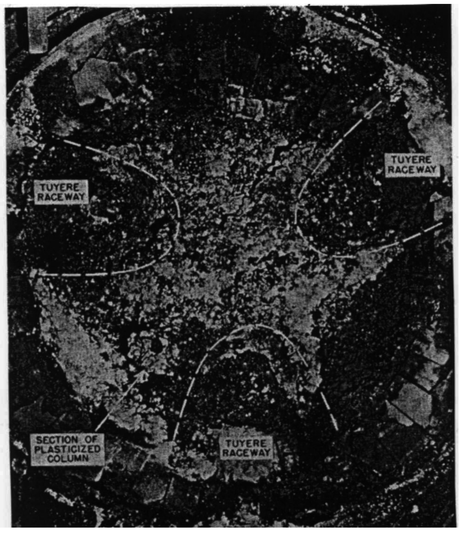
In the bosh, they found an abundance of frozen droplets or beads of molten metal, molten gangue, and glazed lime [11,12]. These beads were probably trickling down towards the hearth at the bottom. Also, just above the tuyeres, there were three large masses of material with loose material on the side. These masses together with the tuyere raceways probably formed the active coke zone where significant melting took place (Figure 1). Droplets of frozen metal began to appear about one-third of the way down the bosh. While the metal beads had decreasing sulfur content down the furnace, the slag beads had an increasing content. Hence, this suggests that sulfur was probably removed by slag-metal contact, particularly in the lower bosh zone where significant changes in the sulfur content were observed.
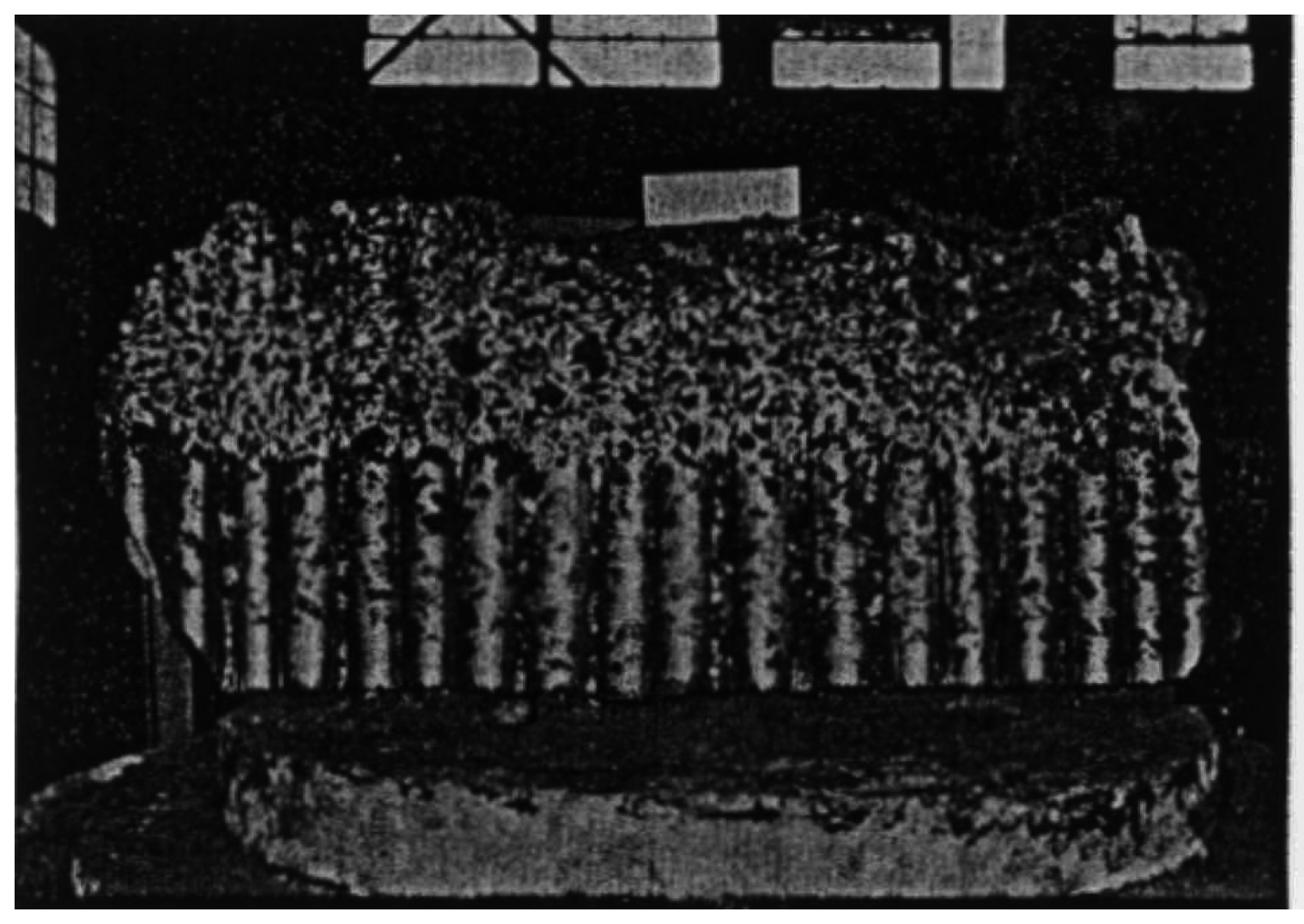
At the bottom of the blast furnace, which is also known as the hearth, a huge mass of frozen material was found [13]. This mass consisted of a slag layer on top of a frozen molten metal layer with coke mixed throughout (Figure 2). Also, beads of metal were found throughout the slag layer. They were probably trickling down towards the molten iron at the bottom. Metal beads in the slag layer had only half the sulfur content of beads above the slag layer. The high basicity of the slag probably aided in the reduction of sulfur from the metal beads into the slag. Also, the average silicon content of the frozen hearth metal was considerably less than the silicon contained in the beads above the metal layer [14]. This drop in the silicon of the hearth metal might be explained by the reoxidation of silicon at the slag-metal interface by the metallic oxides in the slag.
In short, Bosley et al.’s work had clarified certain aspects of blast furnace operation which had been widely assumed earlier before the study [2]. Such was the case of the discovery of the frozen outlines of the raceway (Figure 1). Furthermore, they showed new findings to the iron-making community at that time [2]. Their work offered a detailed insight into the variation of sulfur content down the furnace and the corresponding causal analysis. They also showed that the flux and the gangue do not combine into a common slag until just above the active tuyere zone [2]. In 1970, there was a similar study done by Murarev et al. in the former Soviet Union [3]. These American and Russian findings paved the way for subsequent blast furnace quenching by the Japanese in the 1970s.
3. The Iron and Steel Institute of Japan (ISIJ) Studies (1970)
3.1. Background Information
Towards the 1970s the Japanese had developed the technology to produce steel to compete with North American production [15]. Japan’s blast furnace operation was known for their stabilization techniques and production in low-Si operation [16]. Much of this could be attributed to their continuous effort in the research and development of blast furnace operation. In a period of 10 years (presumably in the 1970s), as many as four experimental and nine operational furnaces were closed down and submitted to scientific research. The methods of quenching used were similar to the U.S. Bureau of Mines case (1959) [17]. The experimental furnaces were all cooled with nitrogen. The operational furnaces were quenched with water except for the Nagoya 1 BF which was quenched with nitrogen. The nine operational furnaces that will be frequently mentioned in the paper include: Hirohata 1 BF, Kukioka 4 BF, Kawasaki 2, 3, and 4 BF, Tsurumi 1 BF, Chiba 1 BF, Kokura 2 BF, and Amagasaki 1 BF.
3.2. Details of the Findings
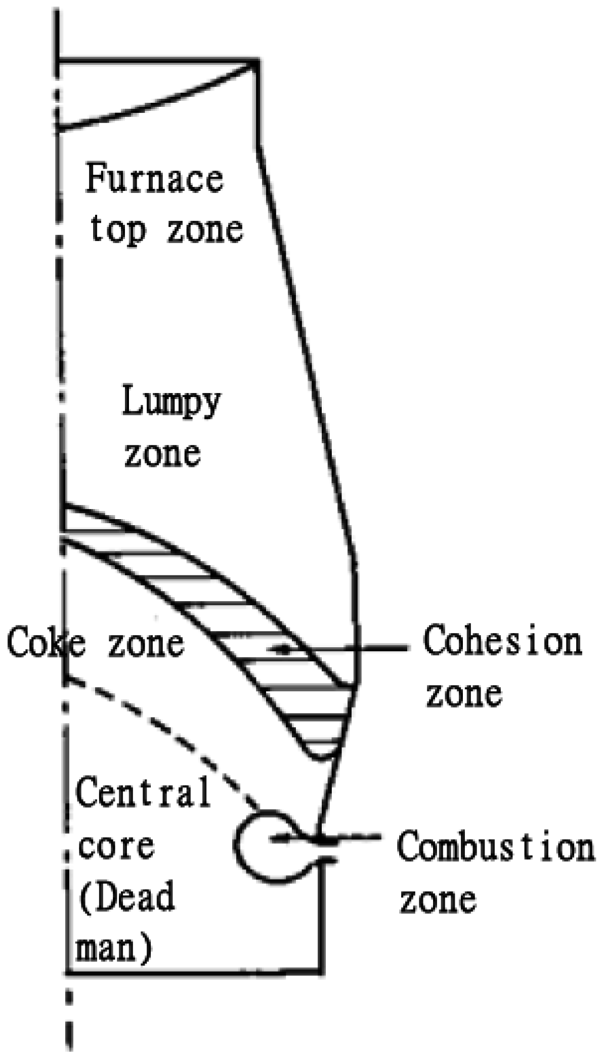
Perhaps the most significant discovery of the Japanese studies was their classification of different zones within the furnace (Figure 3, Figure 4 and Figure 5):
- The top part with the layered ore and coke as charged.
- The lumpy zone (stack zone) where coke and ore particles make a stratified descent down the furnace.
- The cohesion zone where ore is softened, fused, and melted in accordance with the state of gas flow from the tuyeres.
- The active coke zone which is situated below the cohesion zone where droplets of iron ore and slag interact with the coke as they percolate down to the hearth.
- The stagnant coke zone (dead man) is right below the active coke zone between the tuyeres where the reaction does not occur. This conical mass acts to support the burden of the furnace and as a path for the droplets of metal and slag to trickle down to the hearth. The Japanese refer to this zone as the core.
- The combustion zone which is a zone where hot blasts from the tuyeres react with coke to generate the heat needed to melt the iron. The air blasts form cavities as a result of the swirling motion of the coke particles, producing raceways.
- The hearth which is composed of the slag layer on top of the metal layer, both filled with coke, which is coagulated near the bottom.
In terms of burden behavior, several common features were found among all the furnaces. In the top part of the furnace, ore layers and coke layers descended down in their layered arrangement. This pattern continued until the ore layers were melted down. The same descent behavior was observed in the U.S. Bureau of Mines case (1959) [18]. Also, as the burden descended, the angle of inclination and the layer thickness decreased. The decrease of the angle of inclination was largely due to the shaft angle, contraction and melting of the ore layers, and their collapse into the raceway further down the furnace.
It is important here to note several peculiar phenomena occurring in a few of the furnaces. In the Kukioka 4 BF and Chiba 1 BF furnaces, the coke and ore layers formed a mixed layer of burden at the furnace wall instead of retaining the stratification. The Japanese named this phenomenon the wall trouble, which is a variation of the basic pattern [4]. In the Tsurumi 1 BF furnace, the radial distribution of the ore layer was significantly different between the top five to six layers and the layers beneath them. O. Tajima in his report, submitted to the 54th Committee of Ironmaking of the Japan Society for the Promotion of Science (JSPS) in 1978, suggested that this difference is due to the fluidization of the middle portion of the coke layer following a change in the top gas flow distribution when an ore layer of lesser gas permeability was charged [4].
Another observation of the stack was the asymmetrical descent of the burden [7]. This is largely due to the non-uniform combustion rate of coke at each tuyere and the uneven flow resistance of the burden. All these affect the formation of the cohesion zone. It was also observed in the Kokura 2 BF furnace that the location of the disappeared cohesion zone and the higher degree of the decrease in the layer inclination corresponded to a higher blast volume (larger tuyeres). The Kokura 2 BF furnace had tuyeres of larger diameter on the east and west sides compared to the north and south sides. A higher blast volume also meant a higher rate of melting and a higher descending rate of the burden.
All furnaces showed that the cohesion zone was characterized by a number of annular layers of fused ore and they disappeared by dripping away along the core slope [12]. Depending on the operating conditions, the shape of the cohesion zone can be V, W or inverse V. It was concluded that the factors affecting the shape of this region were the distribution of charged materials, the descent behavior of materials in the lumpy zone and cohesion zone, the conditions in the combustion zone and the state of coke inflow at the combustion zone.
In the Kokura 2 BF furnace, the use of smaller tuyeres in the north-south direction caused the cohesion zone to descend to the tuyere level. This observation suggested that the blast volume plays a major role in the position of the cohesion zone. As mentioned earlier in the study of the burden, a higher blast volume will result in a higher melting rate. In this case, smaller tuyeres meant lower blast volumes which led to lower melting rates. Only the area which is closer to the tuyeres was melted. This thus resulted in a cohesion zone close to the tuyeres.
Examining the combustion zone, further ahead before the raceway extends towards the core, there exists a shell consisting of small-size coke, metal, and slag. It was suggested based on the Japanese studies that the formation of the shell started with the densification of coke particles closing together, then with the viscous slag clogging the gaps between the particles [6]. Studying the lower part of the raceway, the Japanese found that traces of shell were found frequently in a layered order (stratified) and that many dark coke particles existed with numerous depressions on the surface (pockmarked) between the shell and the wall of the raceway lower part [8]. The metal and slag that drips down through this path would have a different composition than if they were to drip down through the core. Also, the movement of the coke here would be very sluggish.
Furthermore, the shape of the raceway is affected by the permeability distribution of the burden [8]. It was observed in the Kawasaki 3 BF furnace, when the burden at the center has a higher proportion of ore, the central gas flow would be weakened and the raceway region would extend less towards the core, also causing a lesser flow of gas towards the core.
Elements such as Na, K, Zn, S, Si, Al, and Mg that circulate in the furnace can cause operational problems such as the formation of ansatz, overheating of the tuyere front, changes in coke properties, and changes in the composition of the hot metal [10]. One of the major problems in analyzing these elements during the study of the quenched samples was the influence of water quenching [10]. Only compounds that were in forms which are relatively stable to water could be observed in the quenched samples. This might not be a true representation of the contents of the furnace. Also, the analysis of circulating elements was possible only with solid samples. The quenching did not allow examination of their gaseous counterparts. Furthermore, there were some changes in the microscopic state during cooling. For these few reasons, the behavior of sulfur in coke was inconsistent and the alkalis in the lower core had unusually high concentrations. The maximum content of alkalis was found in the lower part of the cohesion zone and the distribution reflected the shape of the zone. Hence, it was concluded that ascending gaseous alkalis originate from the combustion or dripping zone. Distribution for the S also reflected the cohesion zone. The circulating region of the alkalis spanned from the 1000 °C zone down to the tuyere level. The circulating region of the Zn element spanned from the middle part of the lumpy zone of 900–1250 °C to the cohesion zone. Since quantitative analysis for this region was difficult, it was assumed for the Si that SiO2 will vaporize and reduce as SiO, which ascends through the furnace and flows out of the combustion zone.
Although there was a great anticipation as to what will be discovered in the hearth to help refine the composition of the pig iron, no conclusive evidence was obtained as to how the droplets of metal and slag had been interacting quantitatively during active operation [6]. The Japanese did, however, suggest some basic notions regarding the formation of slag [5]. Several major factors contributing to the formation of slag were the reduction of silicon dioxide, the generation of silicon oxide and the separation and scattering of coke ash. Also, in the test blast furnaces, a tendency of the Si, Mn, and Ti contents in metal droplets to rise to an extremely high value near the tuyere level, dropping again in the hearth, was seen. However, operational furnaces did not show such a clear trend [13]. It was concluded that the gas flowing out of the combustion zone to the melting zone had a strong influence on the Si distribution in the lower part of the furnace. The S distribution, on the other hand, was probably influenced by the shape of the cohesion zone and its gas flow distribution. The P element was largely affected by the distribution of charged material while the Mn and C distributions had a direct correlation with the Si content.
4. Conclusions
All in all, the Japanese studies managed to clarify basic notions regarding the burden behavior of the stack zone, the factors that affect the shape of the cohesion zone, the behavior of the circulating elements except for SiO2, the slag formation phenomena, and the relation between the raceway shape and permeability distribution of the burden. Topics that still had to be researched included the movement of material within the center core of the furnace, the locations, paths and quantity of absorption of SiO2, the force that supports the steady descent of the cohesion zone, and the quantitative interaction of slag and metal droplets during active operation. There were no contradicting results compared with the U.S. Bureau of Mines study conducted by Bosley et al. in 1959 [2]. Both findings agreed on numerous topics including the descent behavior of burdens, the variation of circulating contents, particularly the sulfur content, and the movement of metal and slag trickling down the furnace.
The results from the Japanese studies were subsequently utilized in improving furnace operation. The dissection of blast furnaces had clarified to a large extent the burden behavior and descent through the furnace. It had also shown how much this affected furnace operation. This and other discoveries led to the clarification of numerous control points in the furnace. Sensors were used to measure furnace variables at such points. Using the information obtained through these sensors, an estimation model was used, making furnace operations more predictable. This thus enables the stable operation of the furnace. Also, the dissection works had signified the importance of the cohesive zone. Iron-makers were more aware of the shape and position of the cohesive zone and their effect on blast furnace operation. By predicting the shape and position of the zone, they were able to improve the control of the process.
Conflicts of Interest
The author declares no conflict of interest.
References
- McCutcheon, K.C.; Marshall, W.E. Barnes: Procedure Used in Quenching and Digging Out a Blast Furnace and Some Results. In Proceedings of the AIME Blast Furnace, Coke Oven and Raw Materials Conference, Pittsburgh, PA, USA, 2–4 April 1951; pp. 217–221.
- Bosley, J.J.; Melcher, N.B.; Harris, M.M. Method for producing high-temperature cement in the blast furnace. J. Met. 1959, 11, 610–615. [Google Scholar]
- Muravev, V.M.; Mischenko, M.I. Physical chemistry of steelmaking. Stal. Eng. 1970, 7, 591. [Google Scholar]
- Omori, K. Blast Furnace Phenomena and Modeling; Elsevier Applied Science: London, UK, 1987; pp. 3–63. [Google Scholar]
- Sasaki, M.; Lino, K.; Suzuki, A.; Okuno, Y.; Oshizawa, K.Y. Formation and Melt-Down of Softening-Melting Zone in Blast Furnace: Report on the Dissection of Blast Furnaces 3. Tetsu Hagane 1976, 62, 559–569. [Google Scholar]
- Kuwabara, M.; Ma, Z. Further Insights into Blast Furnace Phenomena and Modeling for Researchers and Operators. In Proceedings of the Advances in Theory of Ironmaking and Steeimaking, Banga, India, 9–11 December 2009; pp. 184–191.
- Shimomura, Y.; Nishikawa, K.; Arino, S.; Katayama, T.; Hida, Y. On the Inside State of the Lumpy Zone of Blast Furnace: Report on the Dissection of Blast Furnaces 2. Tetsu Hagane 1976, 62, 547–558. [Google Scholar]
- Burgess, J.M. Fuel Combustion in the Blast Furnace Raceway Zone. Prog. Energy Combust. Sci. 1998, 11, 61–82. [Google Scholar] [CrossRef]
- Ondrey, G.; Parkinson, G.; Moore, S. Blast Furnaces Make Way for New Steel Technology. Chem. Eng. 1995, 102, 37–41. [Google Scholar]
- Patankar, S. Numerical Heat Transfer and Fluid Flow; McGREW-Hill: New York, NY, USA, 1980; pp. 27–51. [Google Scholar]
- Yagi, J. Mathematical Modeling of the Flow of Four Fluids in a Packed Bed. ISIJ Int. 1993, 33, 619–639. [Google Scholar] [CrossRef]
- Hattori, M.; lino, B.; Shimomura, A.; Tsukiji, H.; Ariyama, T. Development of Burden Distribution Simulation Model for Bell-jess Top in a Large Blast Furnace and Its Application. ISIJ Int. 1993, 33, 1070–1077. [Google Scholar] [CrossRef]
- Childs, K. A Comparison of Operational and Economic Factors of Arc and Induction Furnaces. In Proceedings of the BCIRA Conference on Electric Melting and Holding Furnaces in the Ironfounding Industry, Loughborough, UK, 20–22 September 1967; p. 463.
- Orechkin, L.M. On the Design of the Blast-furnace Well (Contribution to the Discussion on the Design and Durability of the Hearth and Well of the Blast-furnace). Metallurgist 1963, 7, 526. [Google Scholar] [CrossRef]
- Chirikhin, V.F.; Gal’perin, G.S.; Milyuts, V.G.; Bocharnikov, A.F.; Vostrikov, V.G. Treatment of low-alloy steel with argon outside the furnace. Metallurgist 1987, 31, 245–247. [Google Scholar] [CrossRef]
- Tsimbal, V.P.; Kustov, B.A.; Aizatulov, R.S.; Mochalov, S.P.; Shapirov, K.M. A new continuous metallurgical process based on principles of self-organization. Metallurgist 1995, 39, 212. [Google Scholar] [CrossRef]
- Ovcharenko, N.L. On the Durability of the Hearth and Well of the Blast-furnace (Contribution to the Discussion on the Construction and Durability of the Hearth and Well of the Blast-furnace). Metallurgist 1962, 6, 466–467. [Google Scholar] [CrossRef]
- Arzamastsev, E.I.; Baryshnikov, V.G.; Baryshnikov, G.I.; Vdovin, S.V.; Rempel, A.N.; Gudov, V.I. Treatment of Ball-bearing Steel Outside the Furnace with Synthetic Slag after Removal of the Furnace Slag. Metallurgist 1981, 25, 14–16. [Google Scholar] [CrossRef]
Figure 1.
Photograph of the frozen tuyere zone. Reproduced with permission from [4], Springer, 1987.
Figure 1.
Photograph of the frozen tuyere zone. Reproduced with permission from [4], Springer, 1987.

Figure 2.
Cross-section of the frozen hearth. Reproduced with permission from [4], Springer, 1987.
Figure 2.
Cross-section of the frozen hearth. Reproduced with permission from [4], Springer, 1987.

Figure 3.
Zones within the blast furnace. Reproduced with permission from [4], Springer, 1987.
Figure 3.
Zones within the blast furnace. Reproduced with permission from [4], Springer, 1987.

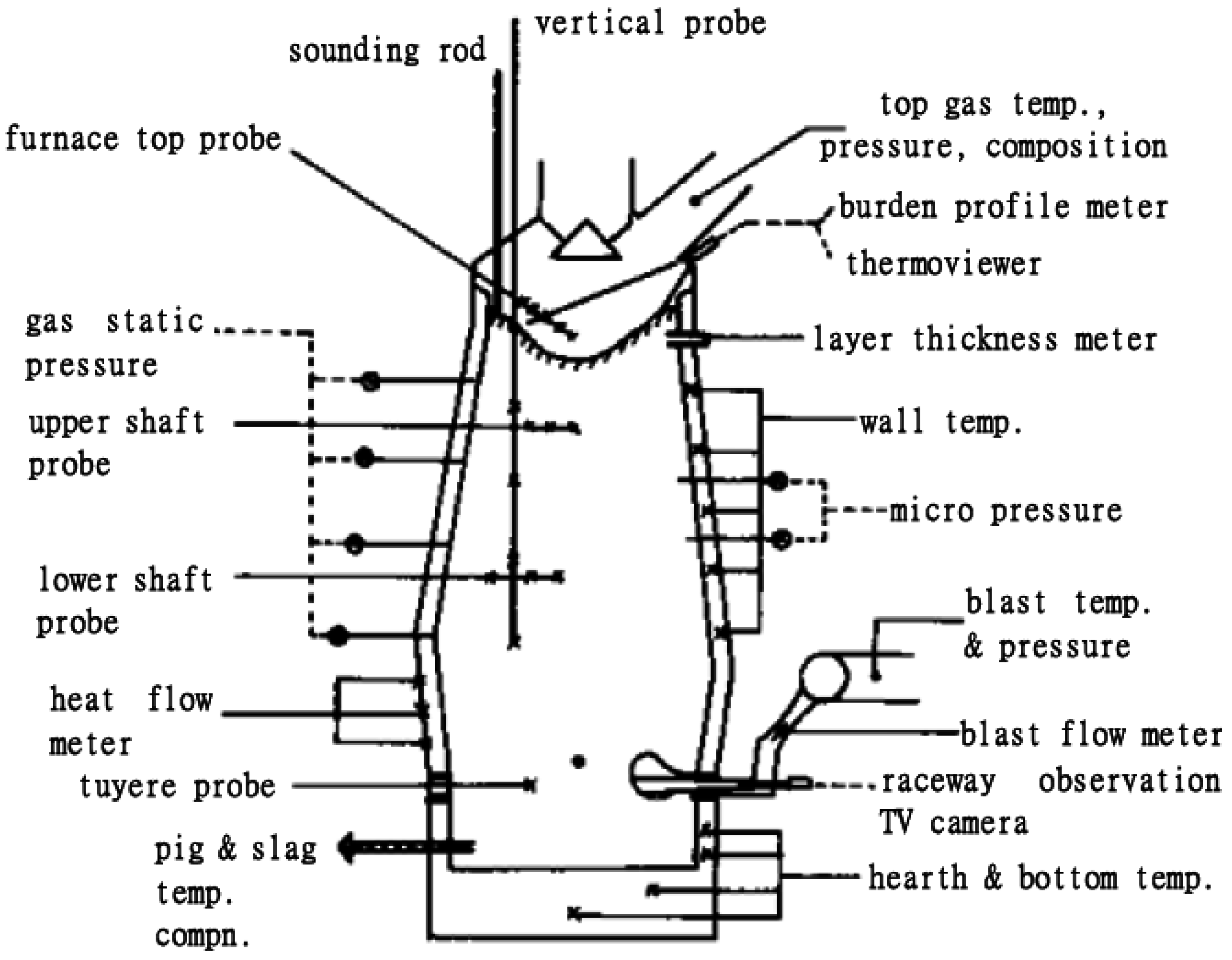
Figure 4.
Instrumentation of blast furnace before the dissection works (pre-1970). Reproduced with permission from [4], Springer, 1987.
Figure 4.
Instrumentation of blast furnace before the dissection works (pre-1970). Reproduced with permission from [4], Springer, 1987.
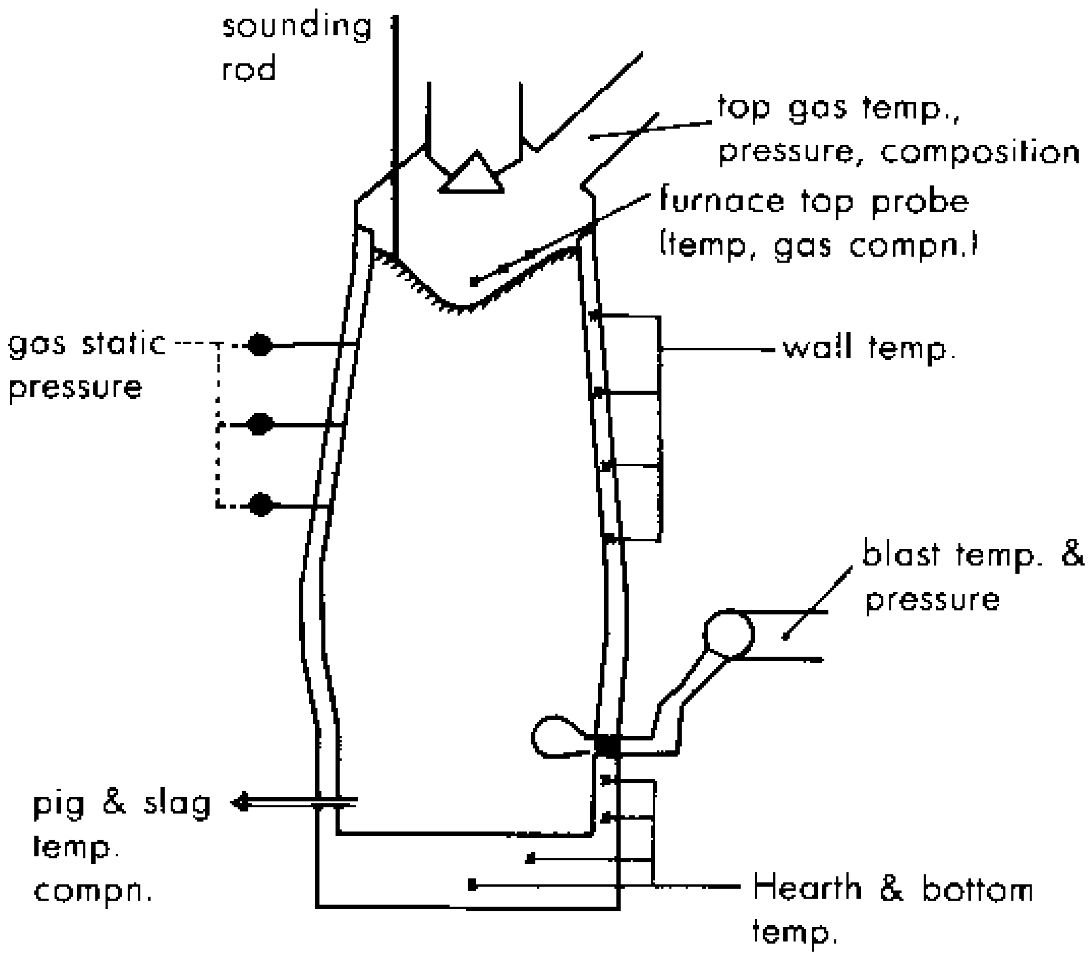
Figure 5.
Instrumentation of blast furnaces built after the dissection works Reproduced with permission from [4], Springer, 1987.
Figure 5.
Instrumentation of blast furnaces built after the dissection works Reproduced with permission from [4], Springer, 1987.

© 2016 by the author; licensee MDPI, Basel, Switzerland. This article is an open access article distributed under the terms and conditions of the Creative Commons Attribution (CC-BY) license (http://creativecommons.org/licenses/by/4.0/).
Share and Cite
MDPI and ACS Style
Zhang, W. A Review on the Dissection of Quenched Blast Furnaces—Spanning from the Early 1950s to the 1970s. Processes 2016, 4, 36. https://doi.org/10.3390/pr4040036
AMA Style
Zhang W. A Review on the Dissection of Quenched Blast Furnaces—Spanning from the Early 1950s to the 1970s. Processes. 2016; 4(4):36. https://doi.org/10.3390/pr4040036
Chicago/Turabian StyleZhang, Wei. 2016. "A Review on the Dissection of Quenched Blast Furnaces—Spanning from the Early 1950s to the 1970s" Processes 4, no. 4: 36. https://doi.org/10.3390/pr4040036
Note that from the first issue of 2016, this journal uses article numbers instead of page numbers. See further details here.