The Optimization Design of a Novel Slotted Microstrip Patch Antenna with Multi-Bands Using Adaptive Network-Based Fuzzy Inference System


Abstract
:1. Introduction
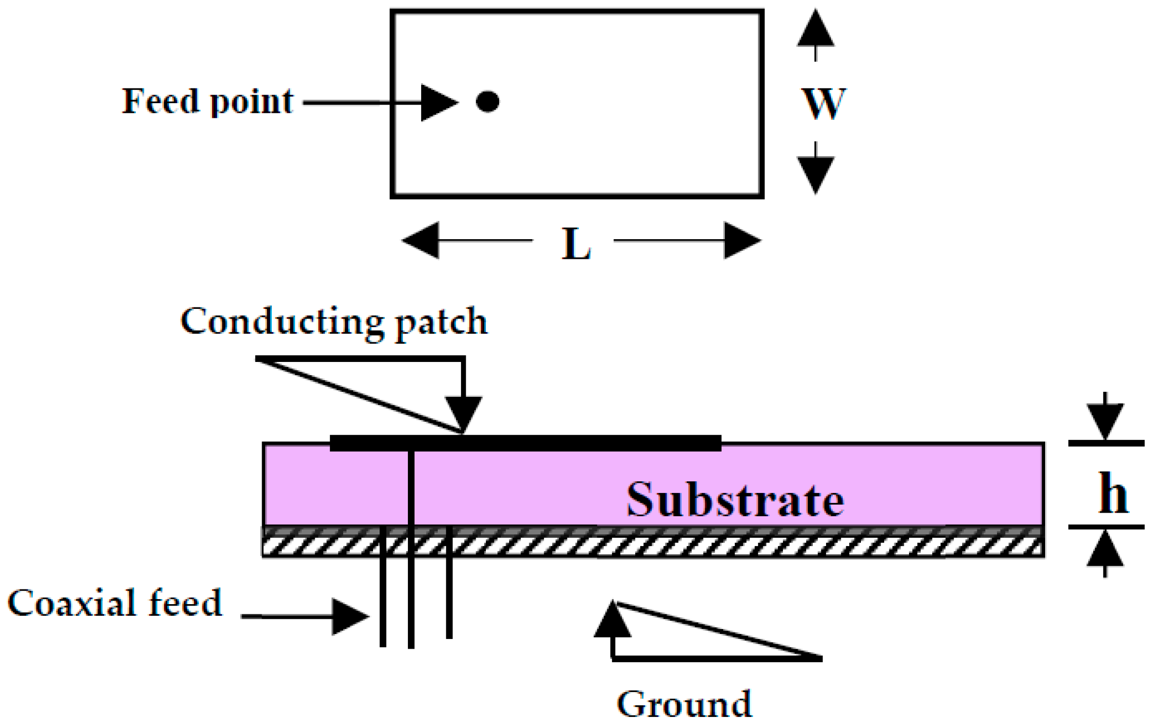
2. Resonant Frequency of Rectangular Microstrip Antenna with Slots Parallel to Resonance Edges
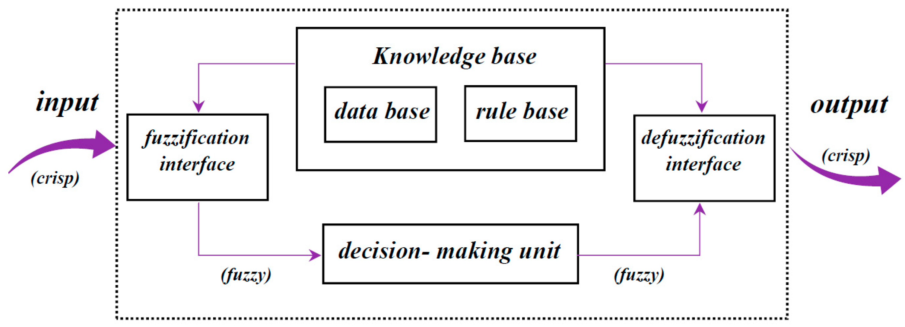
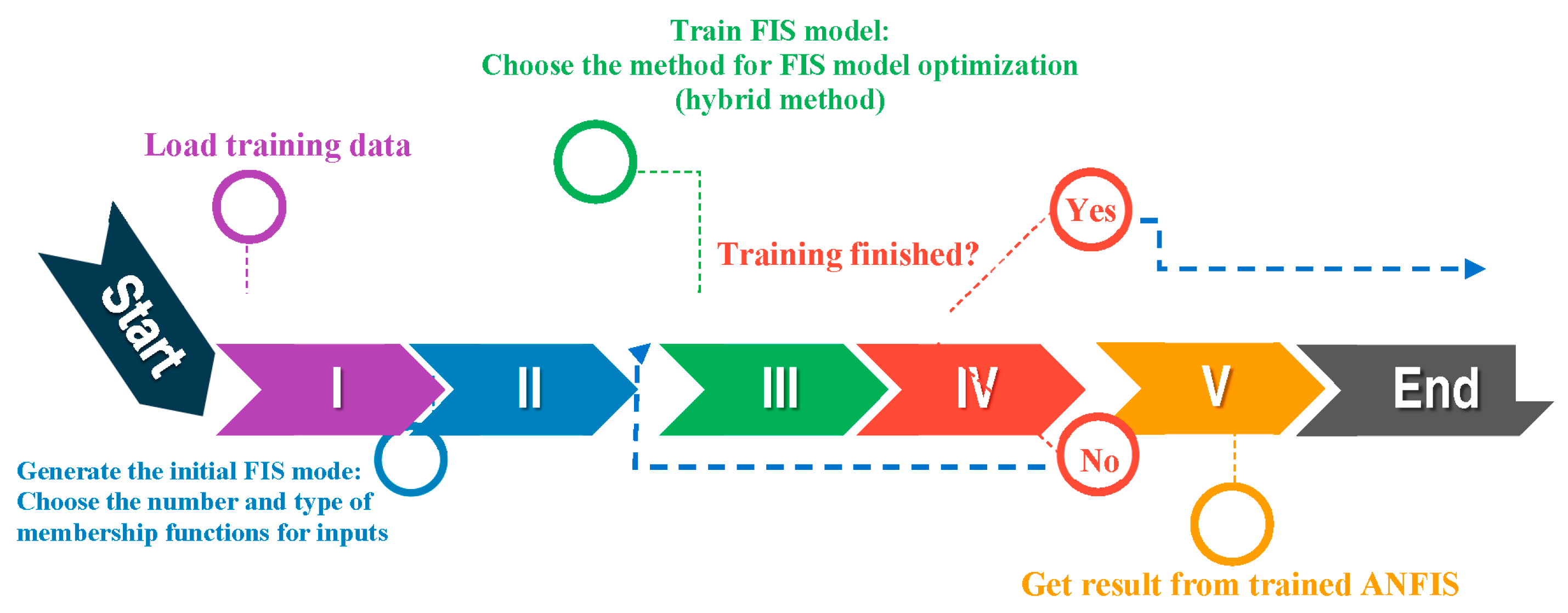
3. Adaptive Neuro-Fuzzy Inference System (ANFIS)
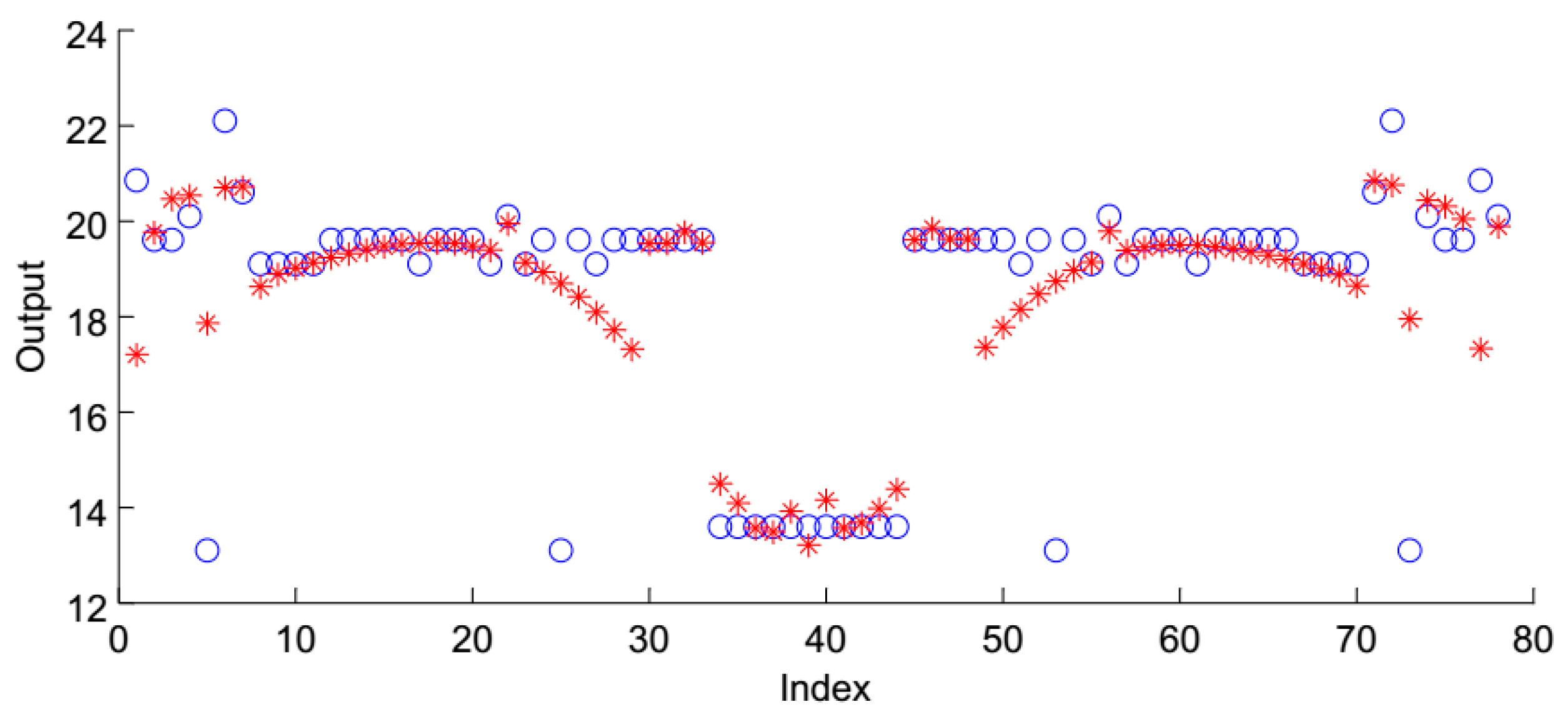
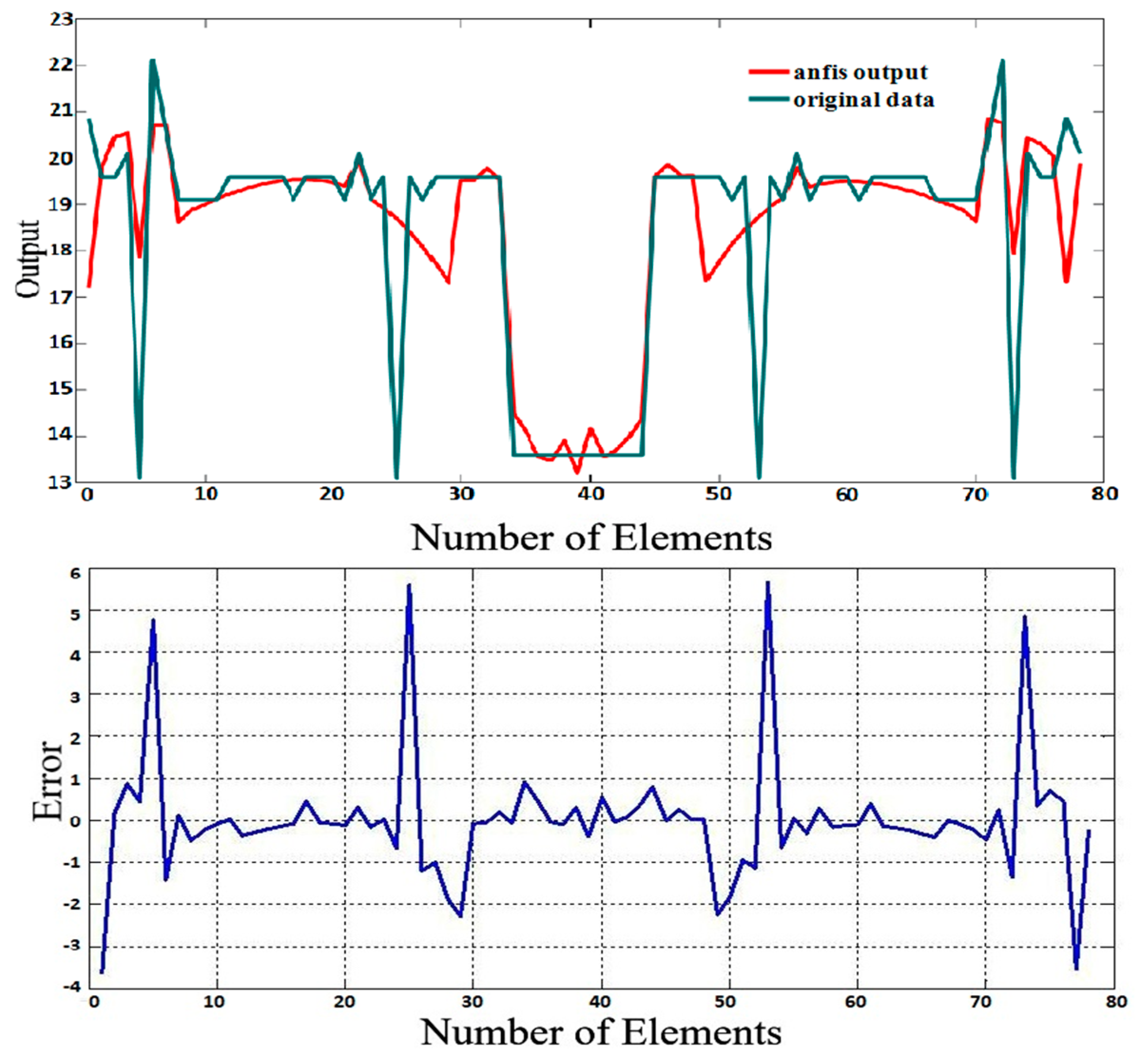
4. How to Take Advantage of the ANFIS in Calculating the Resonant Frequency of Rectangular Antennas Operating at Multi Bands
5. Conclusions
Author Contributions
Conflicts of Interest
References
- Garg, R.; Bhartia, P.; Bahl, I.; Ittipiboon, A. Microstrip Antenna Design Handbook; Artech House: Norwood, MA, USA, 2001. [Google Scholar]
- Wong, K.L. Compact and Broadband Microstrip Antennas; J. Wiley and Sons: New York, NY, USA, 2002. [Google Scholar]
- Chen, W.S. A novel broadband design of a printed rectangular slot antenna for wireless applications. Microw. J. 2006, 49, 122. [Google Scholar] [CrossRef]
- Azadegan, R.; Sarabandi, K. Bandwidth Enhancement of Miniaturized Slot Antennas Using Folded, Complementary, and Self-Complementary Realizations. IEEE Trans. Antennas Propag. 2007, 55, 2435–2444. [Google Scholar] [CrossRef]
- Zhang, L.; Jiao, Y.C.; Zhao, G.; Song, Y.; Wang, X.M.; Zhang, F.-S. A novel CPW-FED monopole antenna for multiband operation. J. Electromagn. Waves Appl. 2008, 22, 741–747. [Google Scholar] [CrossRef]
- Sze, J.Y.; Wong, K.L. Bandwidth enhancement of a microstrip line-fed printed wide-slot antenna. IEEE Trans. Antennas Propag. 2001, 49, 1020–1024. [Google Scholar] [CrossRef]
- Guney, K.; Gultekin, S.S. Artificial Neural Networks for Resonant Frequency Calculation of Rectangular Microstrip Antennas with Thin and Thick Substrates. Int. J. Infrared Millim. Waves 2004, 25, 1383. [Google Scholar] [CrossRef]
- Gultekin, S.S.; Guney, K.; Sagiroglu, S. Neural networks for the calculation of bandwidth of rectangular microstrip antennas. Appl. Comput. Electromagn. Soc. (ACES) J. 2003, 18, 46–56. [Google Scholar]
- Karaboga, D.; Guney, K.; Sagiroglu, S.; Erler, M. Neural computation of resonant frequency of electrically thin and thick rectangular microstrip antennas. IEE Proc. Microw. Antennas Propagat. 1999, 146, 155–159. [Google Scholar] [CrossRef]
- Guney, K.; Erler, M.; Sagiroglu, S. Artificial neural networks for the resonant resistance calculation of electrically thin and thick rectangular microstrip antennas. Electromagnetics 2000, 20, 387–400. [Google Scholar] [CrossRef]
- Guney, K.; Sagiroglu, S.; Erler, M. Comparison of neural networks for resonant frequency computation of electrically thin and thick rectangular microstrip antennas. J. Electromagn. Waves Appl. 2012, 15, 1121–1145. [Google Scholar] [CrossRef]
- Amanpreet, K.; Gurmohan, S.; Manjit, K. Miniaturized Multiband Slotted Microstrip Antenna for Wireless Applications. Wirel. Pers. Commun. 2017. [Google Scholar] [CrossRef]
- Jiachen, Y.; Huanling, W.; Zhihan, L.; Huihui, W. Design of Miniaturized Dual-Band Microstrip Antenna for WLAN Application. Sensors 2016, 16, 983. [Google Scholar] [CrossRef]
- Naresh, K.; Darimireddy, R.; RamanReddy, A.; Mallikarjuna, P. Design of triple-layer double U-slot patch antenna for wireless applications. J. Appl. Res. Technol. 2015, 13, 526–534. [Google Scholar]
- Liu, S.; Qi, S.S.; Wu, W.; Fang, D.G. Single-Layer Single-Patch Four-Band Asymmetrical U-Slot Patch Antenna. IEEE Trans. Antennas Propag. 2014, 62, 4895–4899. [Google Scholar] [CrossRef]
- Jang, J.S.R. Anfis: Adaptive-network-based fuzzy inference system. IEEE Trans. Syst. Man Cyber. 1993, 23, 665–685. [Google Scholar] [CrossRef]
- Jang, J.S.R.; Sun, C.T.; Mizutani, E. Neuro-Fuzzy and Soft Computing: A Computational Approach to Learning and Machine Intelligence; Prentice-Hall: Upper Saddle River, NJ, USA, 1997. [Google Scholar]
- Bassam, A.; May Tzuc, O.; Escalante Soberanis, M. Temperature Estimation for Photovoltaic Array Using an Adaptive Neuro Fuzzy Inference System. Sustainability 2017, 9, 1399. [Google Scholar] [CrossRef]
- Mashaly, A.F.; Alazba, A.A. Application of adaptive neuro-fuzzy inference system (ANFIS) for modeling solar still productivity. J. Water Supply Res. Technol. AQUA 2017, 66, 367–380. [Google Scholar] [CrossRef]


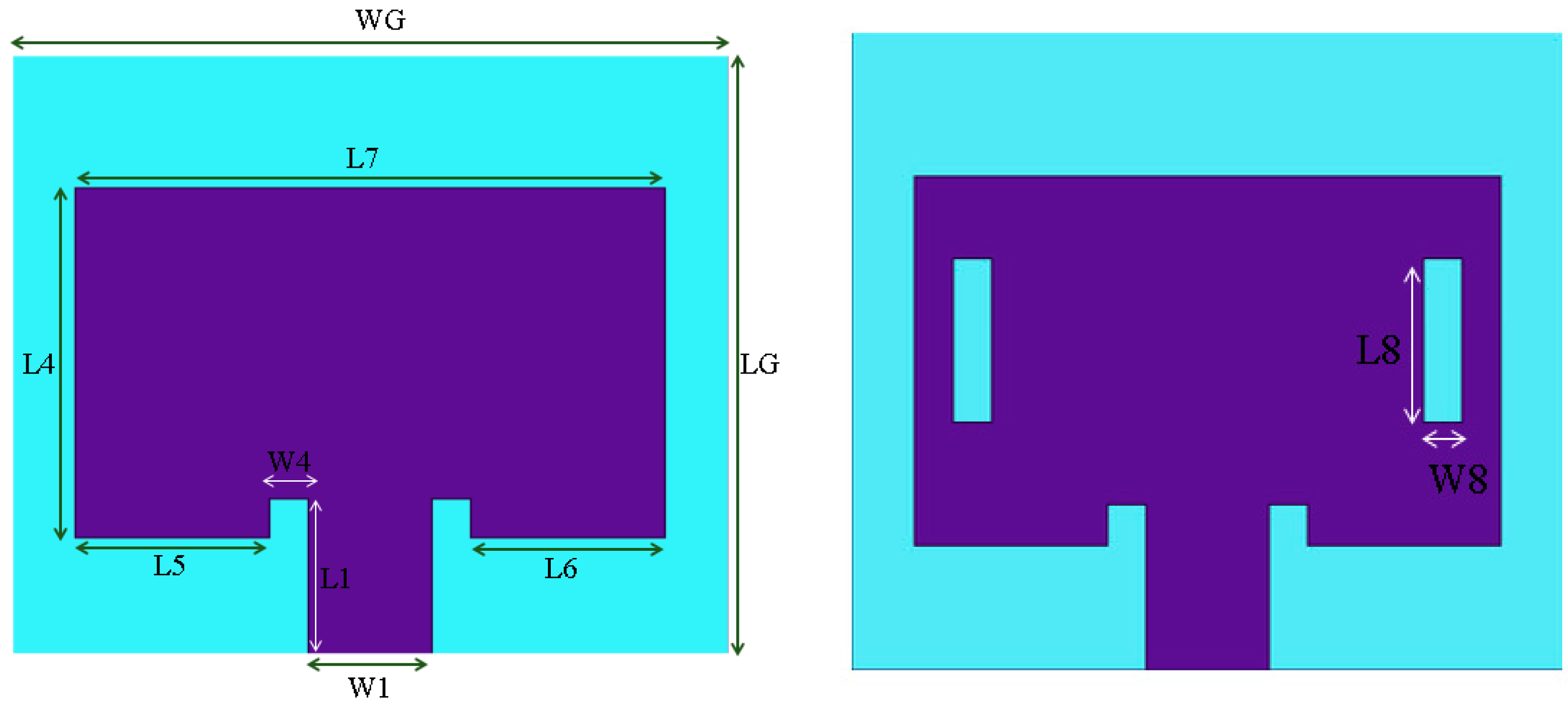
| Parameter | mm | Parameter | mm |
|---|---|---|---|
| L1 = L feed | 3 | LG | 15.528 |
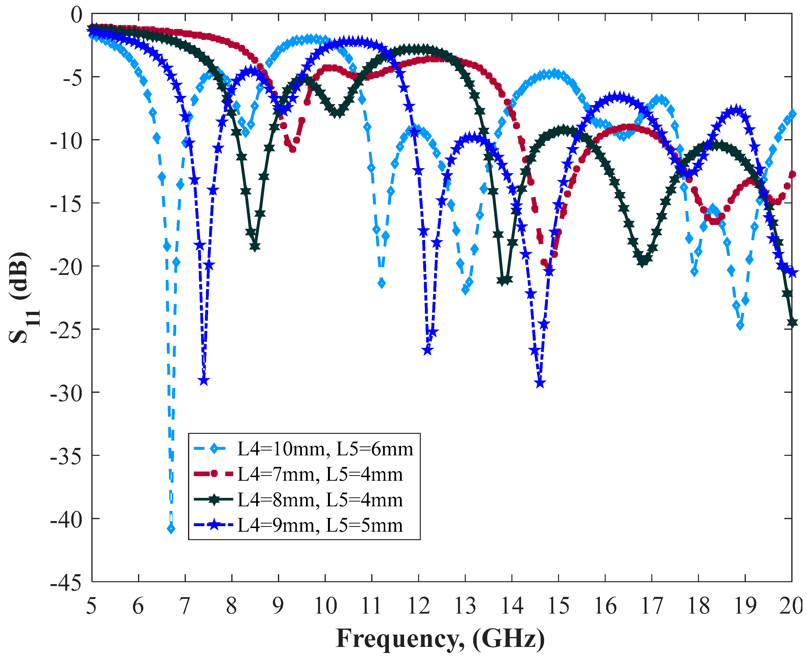
| L4 | 9 | WG | 18.44 |
| L5 | 5 | W4 | 1 |
| L6 | 5 | W1 | 3.2 |
| L7 | 15.2 | - |
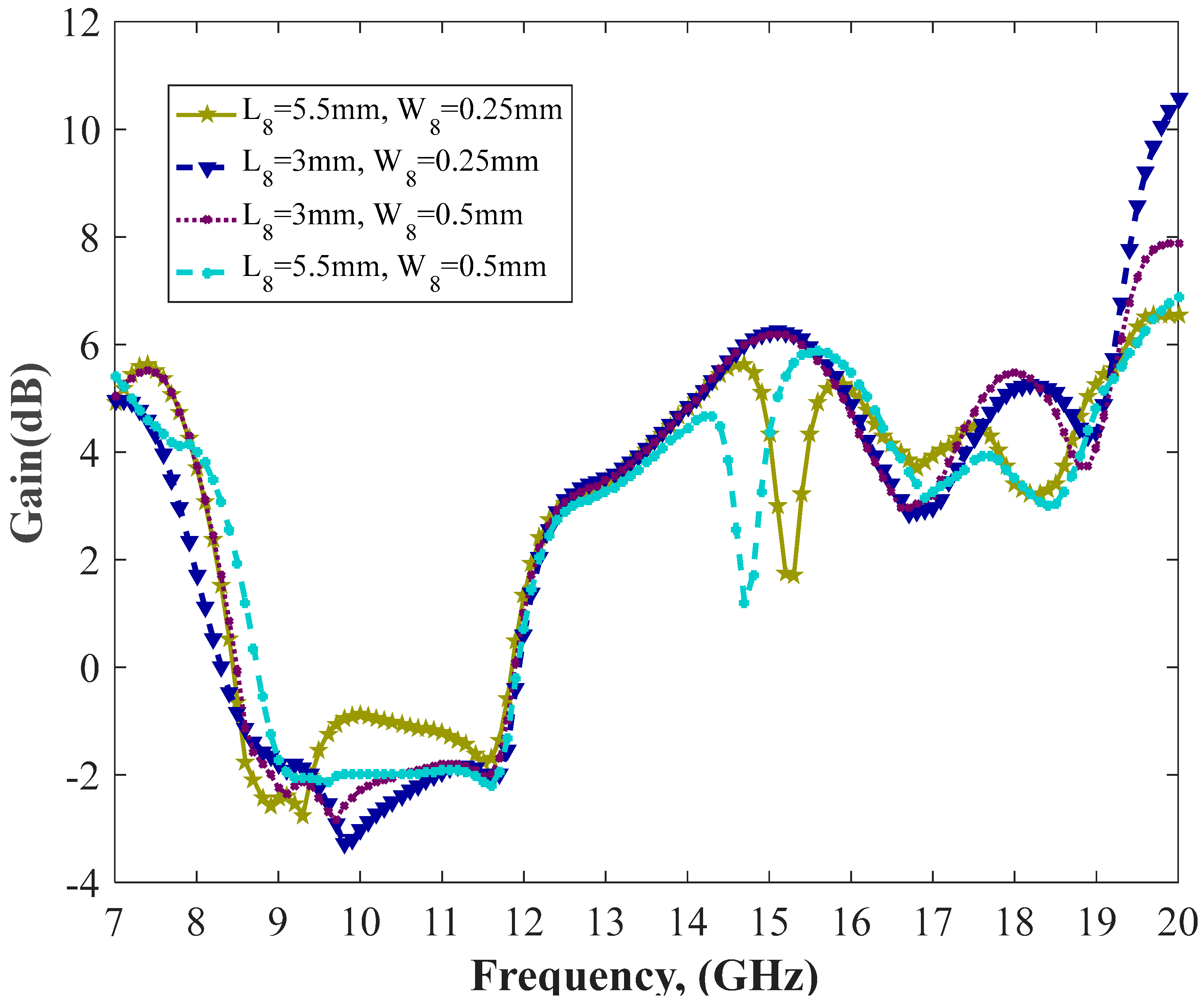
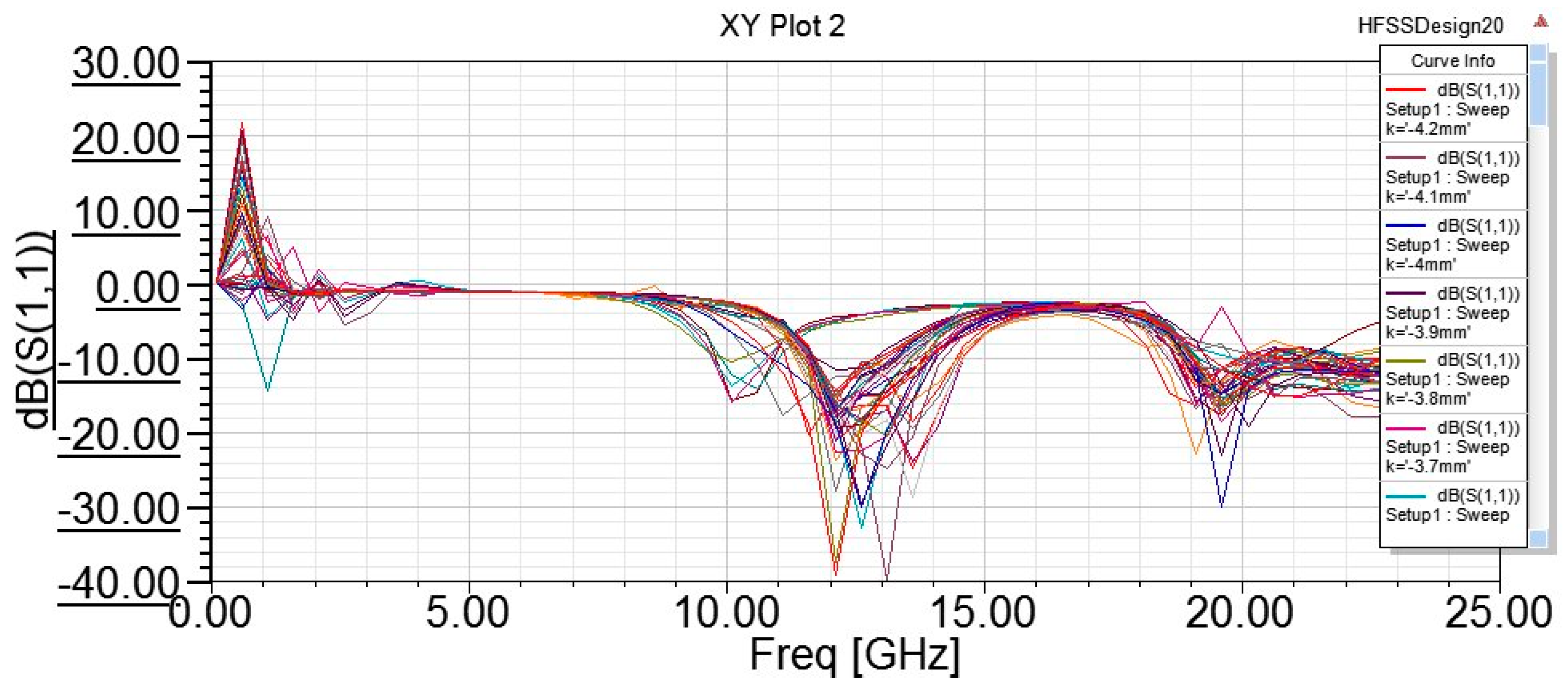
| Microstrip Patch Antenna with Slots (L8 = 7.5 mm, W8 = 0.25 mm) | |||||
|---|---|---|---|---|---|
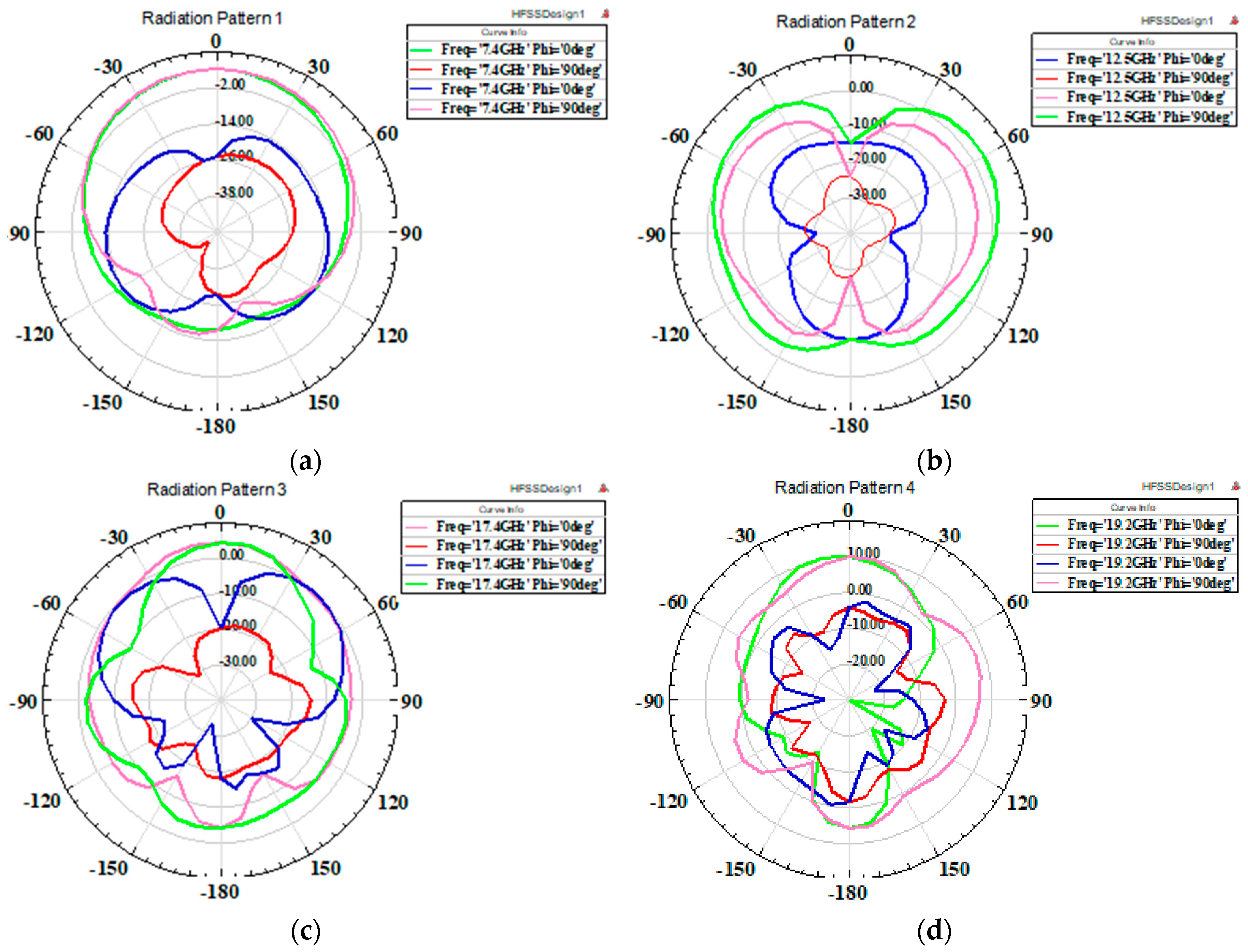
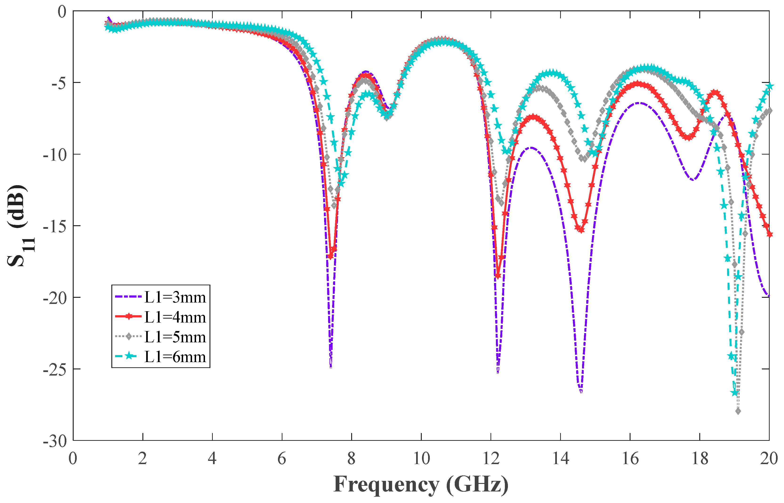
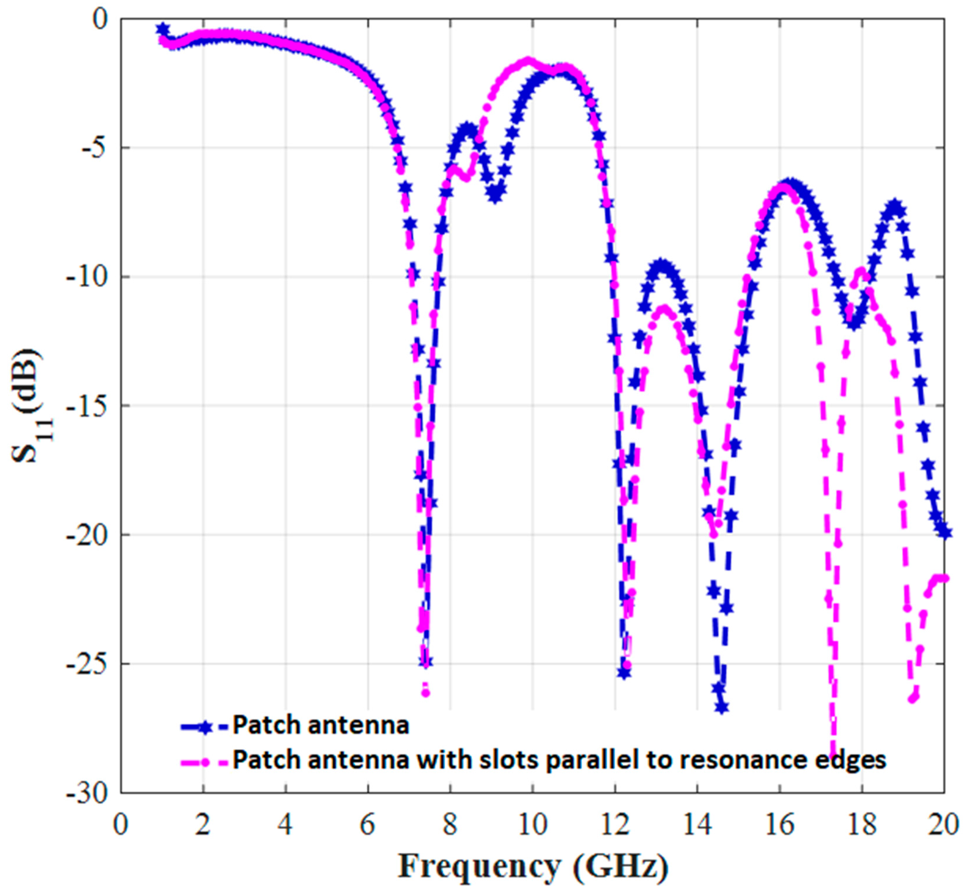
| Resonant Frequency (GHz) | 7.4 | 12.2 | 14.6 | 17.5 | 19.3 |
| Bandwidth | 7–7.8 | 11.9–13.2 & 13.2–15.5 | 16.9–18 | 18–18.9 | 18.9–20 |
| Return loss (dB) | −26 | −33 & −20 | −28 | −18 | −28 |
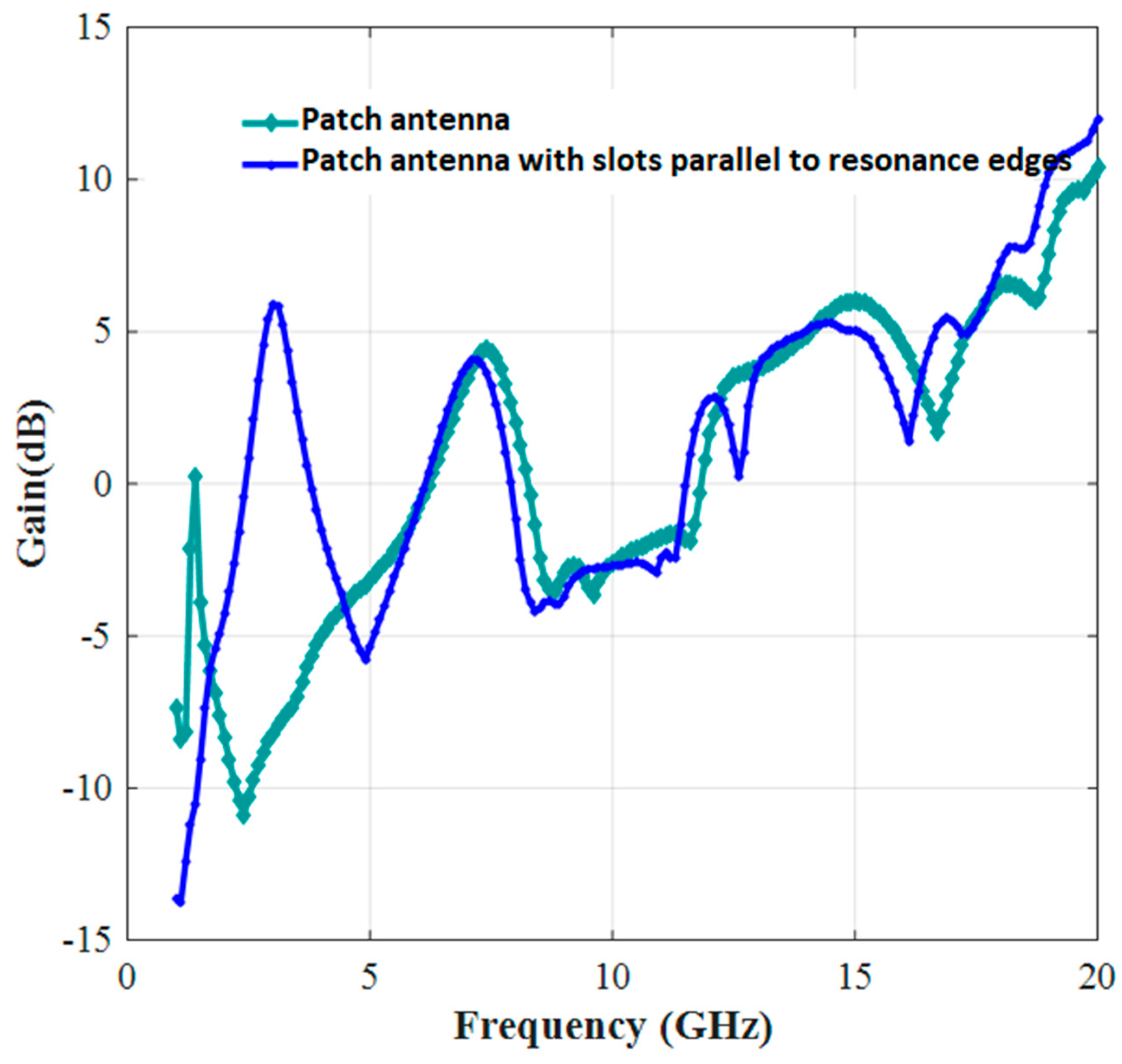
| Gain (dB) | 4 | 2.8 & 5.3 | 5 | 7.75 | 10.8 |
| Reference | Resonant Freq | Max Gain dBi | Size (mm3) |
|---|---|---|---|
| [12] | 3.39/4.29/5.46/5.77 | 8 | 25 × 25 × 1.6 |
| [13] | 2.6/5.45/0.08 | 5 | 29 × 16 × 1.6 |
| [14] | 1.6/1.9/3.8 | 6.58 | 52 × 71 × 1.6 |
| [15] | 3.35/3.70/5.20/5.80 | 9 | 50 × 50 × 5 |
| The Proposed Antenna | 7.4/12.2/14.6/17.5/19.3 | 10.8 | 15.528 × 18.44 × 1.6 |
| MFs | |||||||||
|---|---|---|---|---|---|---|---|---|---|
| Stage | Trapmf | Trimf | Dsigmf | Psigmf | Pimf | Gbellmf | Gaussmf | Gauss2mf | |
| training | MAE | 1.5722 | 1.536 | 1.5386 | 1.5385 | 1.5317 | 1.483 | 1.4653 | 1.5012 |
| RMSE | 2.6385 | 2.6797 | 2.6823 | 2.616 | 2.6066 | 2.3713 | 2.515 | 2.341 | |
| CC | 0.7982 | 0.8213 | 0.8511 | 0.8552 | 0.8695 | 0.8997 | 0.9187 | 0.9234 | |
© 2017 by the authors. Licensee MDPI, Basel, Switzerland. This article is an open access article distributed under the terms and conditions of the Creative Commons Attribution (CC BY) license (http://creativecommons.org/licenses/by/4.0/).
Share and Cite
Abbasi Layegh, M.; Ghobadi, C.; Nourinia, J. The Optimization Design of a Novel Slotted Microstrip Patch Antenna with Multi-Bands Using Adaptive Network-Based Fuzzy Inference System. Technologies 2017, 5, 75. https://doi.org/10.3390/technologies5040075
Abbasi Layegh M, Ghobadi C, Nourinia J. The Optimization Design of a Novel Slotted Microstrip Patch Antenna with Multi-Bands Using Adaptive Network-Based Fuzzy Inference System. Technologies. 2017; 5(4):75. https://doi.org/10.3390/technologies5040075
Chicago/Turabian StyleAbbasi Layegh, Mahmood, Changiz Ghobadi, and Javad Nourinia. 2017. "The Optimization Design of a Novel Slotted Microstrip Patch Antenna with Multi-Bands Using Adaptive Network-Based Fuzzy Inference System" Technologies 5, no. 4: 75. https://doi.org/10.3390/technologies5040075