MUXER—A New Equipment for Energy Saving in Ethernet


1
Faculty of Computer Engineering, Inje University, Gimhae 50834, Korea
2
Team lead and Android Developer, True Corporation, Bangkok 10310, Thailand
*
Author to whom correspondence should be addressed.
Technologies 2017, 5(4), 74; https://doi.org/10.3390/technologies5040074
Submission received: 15 September 2017
/
Revised: 27 October 2017
/
Accepted: 20 November 2017
/
Published: 23 November 2017
Abstract
:Nowadays, the rapidly increasing energy consumption of communication equipment is an economic and environmental problem that needs to be addressed. Small Local Area Networks (LAN) switches in the US alone consume about 8 TWh per year that corresponds to hundreds of millions of US dollars in electricity. A main reason is communication equipment, due to the fact that, Ethernet switches have to active all days even in low-traffic time. There are many approaches to make the switches sensitive with the different traffic load environment, but they have to put some changes to current Ethernet that cause the incompatibility issues. This paper proposes a new device called Modified Multiplexer (MUXER), which can control the power functions of switches without modifying the current Ethernet protocol. The MUXER devices are put before the switches in the network, which provide some functions to transfer incoming Media Access Control (MAC) data frames to the corresponding switches managed by MUXERs. By using the proposed device, the wasted energies in the network can be reduced, especially in the specified low-traffic time. We describe the result of numerical analysis and compare detail power consumption data between a normal and a network where MUXERs are installed. In this work, the explained result shows that if a network administrator can estimate the number of MUXER needed for a particular network and install accordingly, our device can provides a significant energy saving.
1. Introduction
The Internet is rapidly becoming the major consumer of using electricity with measurable impacts. The hubs, switches and routers comprise the core of the Internet in order to guarantee stable and real-time properties at any time. Hence, it causes a large consumption of energy when these devices must be fully activated even if they are in low-traffic conditions for a long time. A report said that the energy consumption of these devices is approximate around 150.4 kilowatt-hour per year (kWh/year) in 2010 [1]. That is the consumption is one Terawatt hours (TWh) per year equivalent to $85 million at $0.085 per kilowatt-hour (kWh) [2] and about 0.75 million tons of CO2 [3]. Also in 2010, it was estimated that 11 percent of the commercial sector electricity consumption was due to electronic office and telecommunication equipment [1]. In addition to that, all of the network equipment that are connected to the Internet via Ethernet links have link speed range from 100 Mbps to 1 Gbps, eventually up to 10 Gbps and 90 percent of the Internet traffics come in and out on Ethernet ports [4]. The energy consumption of each device in Ethernet is small, but since Ethernet is growing up rapidly, and the overall number of Ethernet-connected devices are also increasing. That is, the total of energy consumption increases in huge amount, as we can see in Table 1 [1]. It is estimated that the energy consumption of the Ethernet network devices in the US was approximately 29.7 kWh/year in 2010 [5]. Besides of it, other measurements have shown that, 1 Gbps Ethernet links consume about 4 W more, than 100 Mbps links and 10 Gbps consume even more that is, from 10 to 20 W [6]. Hence, link utilization is the main factor of Ethernet power consumption.
A study reported that energy consumption for network switches is 30% [7], among them rack switches are taking 15%, aggregation switches by 10% finally core switches taking 5%. Since devices like processor and drivers are continuously improving their energy saving techniques, but network equipment’s energy consumption rate are increasing. There is still opportunity to reduce network energy consumption through energy proportionality. Connected links consume up 65% of the total network power [8] just because they use full power, even if the links are idle [9]. The reduction of CO2 emissions by up to 2.85 million metric tons per year can be saved only in U.S if we can reduce the energy consumption of the network equipment significantly [10]. The Energy Efficient Ethernet (EEE) standard, approved by Institute of Electrical and Electronics Engineers (IEEE) in 2010, improves Ethernet energy proportionality by defining a link sleep mode known as Low Power Idle (LPI). Due to some performance issues some vendors still advise their user to stay away from it until its effect on real application is improving [11,12,13].
According to an online source, just to keep network connection stable some devices uses up to 80% of its energy [14]. It also stated that more than 600 TWh of electricity was consumed by such devices in 2013. Some article stated that bandwidth and the number of connections are mostly responsible for energy consumption of Ethernet switch in the usage phase [15].
Currently, there are some approaches that are proposed to overcome Ethernet power consumption. They tried to reduce the use of Ethernet energy by decreasing the link utilization in low traffic conditions or increasing the delay time of MAC frame transactions. Adaptive Link Rate (ALR) [16] or Autonegotiation [17] as a method that switches automatically the data rate of Ethernet full-duplex link to match link utilization. In these approaches, energy savings are achieved by operating at a low link data rate, so that, the network performance, especially packet delay must be in trade-off versus reducing energy consumption. Another approach is IEEE 802.3az Energy Efficient Ethernet (EEE). The main goal of EEE is to stop transaction when there is no data to send and to resume it quickly when new packets arrive. Energy saving is reached when the devices spends a significant fraction in the low power mode. Other alternatives, like Rapid physical layer device (PHY) Selection (RPS) [18], have been also proposed to accelerate the speed change. However, these approaches required the large changes in the Ethernet infrastructure, which are impossible with wide deployment and implementation of Ethernet in the Internet.
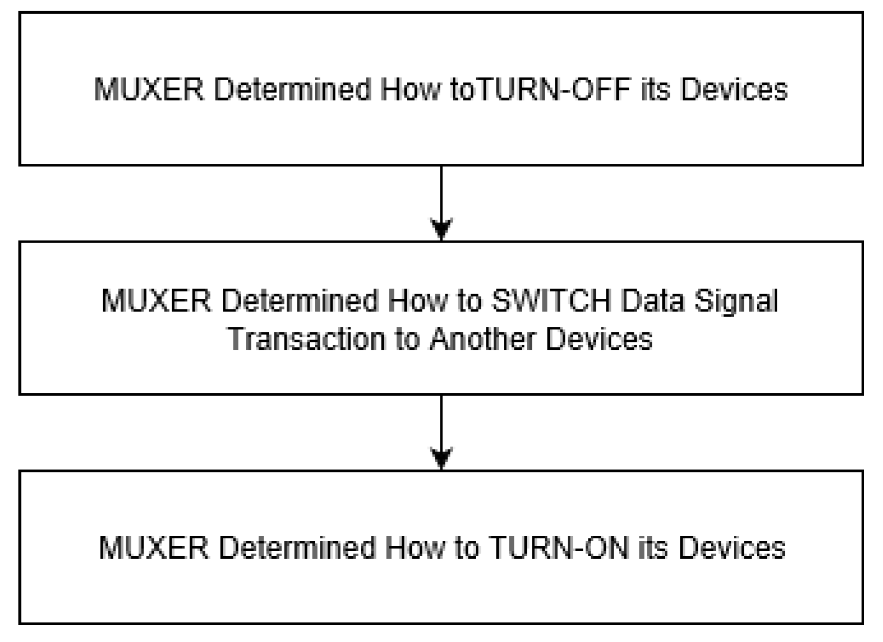
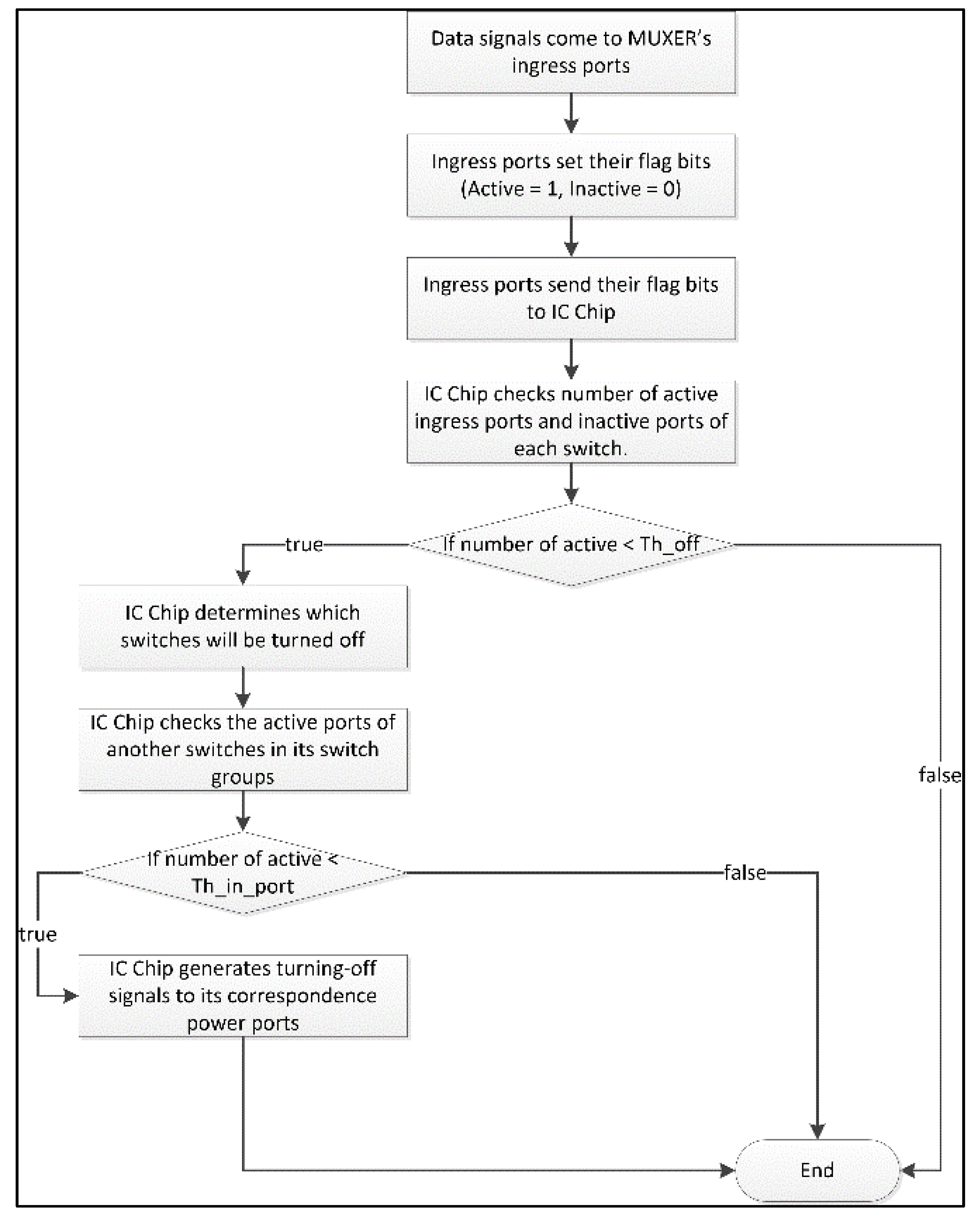
To overcome the disadvantages of current approaches, this paper proposes a different method to reduce the wasted power consumption in low-traffic conditions of Ethernet. The method doesn’t change any feature of the current Ethernet infrastructure. It proposes a new device named MUXER (a set of modified multiplexer) that is put behind end-terminals and before network devices, switches in this paper, to control the power (ON/OFF) of network devices, or to switch data packet transaction to other devices. MUXER must be guaranteed the simplicity, plug-and-play property, and cheap price. The overall process model of this device can be summarized in threefold, as shown in Figure 1. First, it tries to determine the satisfied conditions to generate controlling signals to turn off its network devices. During this process, MUXER has to answer these questions:
- What conditions does it consider to generate a controlling signal to turn off its network devices?
- Which devices of its neighbor MUXERs can contain the more data traffic transferred from its network devices?
- Which actions does MUXER determine to do at the end of this process?
Second, MUXER makes decisions to send turn-off signals to its devices, and switches the data signals to other devices which are determined in the previous process. Final, MUXER tries to contact with its devices and its neighbor MUXERs if it can turn on its devices to increase the performance of networks.
2. Related Work
Different kind of use for network equipment, life cycle of energy along with their impact on environment pollution was explained in some work [19]. From a device manufacturer’s point of view that, network equipment consumes energy proportional to their usage, their main idea was that devices like routers and switches are power proportional [20].
Relationship between network parameters and their effect on power consumption during deployment time of network equipment was discussed in another work where some fuzzy logic based approach was used [21]. Local Area Network (LAN) Power management system feasibility was discussed in Gupta [22], in their work they tested various elements on LAN switches to sleep in a certain time to reduce power consumption. Similar study about energy management of network switches were performed [23]. Another study in this sector presented two forms of power management schemes to reduce the energy consumption of network. They have shown that simple schemes for sleeping or rate adaptation have significant energy savings without noticeably increased packet loss and latency [24]. Some articles have considered isolated switch are in [25,26,27,28], they have mainly modeled the performance of EEE interfaces.
In most of current solutions does not consider, describe or modeled the statistical properties of the traffic. Due to this no predictive information is there which could lead us to suitably controlled (activated/deactivated) link state. The examples in this direction are the self–similar features of some Internet traffic [29], and periodic industrial traffic [30]. EEE strategy performance and best way to use EEE approach was also presented in [31].
There are two manners for energy efficiency in Ethernet: one is to reduce the speed of Ethernet link when there is a little traffic, and another one implements the power-modes to put a network device to sleep and wake it up quickly without a speed change.
The first one has been first proposed by Gunaratne et al. in 2005 as Adaptive Link Rate [16] and was put in the IEEE 802.3 Ethernet standard. It can be achieved through Autonegotiation, which is used to determine the link speed when the Ethernet link is established. This mechanism can reduce the link speed by restarting the Autonegotiation process, and advertising the lower speed to the link [6,32,33,34]. However, the main issue with this approach is that its process takes a long time from a few hundred milliseconds to a few seconds. Rapid physical layer device selection (RPS) is another alternative [18]. It is proposed to accelerate the speed change which is also based on the Autonegotiation process, but does not need to restart this process when agrees a speed change on the links to make a decision on a speed change in a shorter time than previous approach. Although the speed-change mechanisms can decrease the power consumption of the network, but network devices still run continuously that caused the effects of energy efficiency in these mechanisms is not clear when put them into large networks.
The second manner is the option chosen by the IEEE 802.3az [35], which has analyzed the mechanisms to support low-power modes for the different Ethernet speeds, such as 100 Mb/s, 1 Gb/s, and 10 Gb/s. This mechanism ensures the receiver of the device in the low-power mode by periodically sending a short period of activity to refresh the receiver’s state. It is useful when is applied in asymmetric traffic mechanism, as the link direction which has traffic can be active, while another direction is in low-power mode. However, this standard does not define when to enter or exit the lower power idle mode. This approach also need to change the current protocols in Ethernet.
3. Materials and Methods
3.1. MUXER Design Principles
The MUXER design principles focus on MUXER’s design and MUXER’s functions. Our main goal when design a new kind of device as a plug-in for network topology is that we don’t change anything in the current Ethernet infrastructure. First, MUXER must be a simple designed device. It means the functions of MUXER have not to complicate, and MUXER does not need to be a smart device. Second, plug-and-play property is the most important factor of MUXER to guarantee that MUXER can be used anytime, anywhere without configuration. Third, MUXER should become the cheap price device. This price helps MUXER can be bought and deployed easily and fast into the current Internet infrastructure.
To guarantee these goals of MUXER’s design, the functions of MUXER must also be simplicity. In this paper, MUXER included three groups of functions: Turning-off MUXER’s devices, transferring data signals from them to other devices of its neighbor MUXERs, and turning-on MUXER’s devices again. Each group has a sequence of actions. These groups of functions are designed that don’t cause any change in the current network infrastructure and network topology. Hence, their actions are performed easily, and they can transfer data signals without checking the data header of those signals.
In next sections, this paper considers about the position of MUXER in network topology, especially in LAN environment. After that, we describe the detail of the above groups of functions and the communications between MUXER and devices in network topology.
3.2. MUXER in Network Topology
As mentioned above, MUXER has to know when data signals come to it, where these signals need to forward, and how these signals should be transferred. In network topology, there are three positions that could be put MUXER: before the end-terminal, behind end-terminal and before network devices, behind network devices. In here, we proof which position is the best one to put MUXER in network topology. Obviously, MUXER could not be put before the end-terminals, because of the scalability and the deployment capability. In the case of the third position, when MUXERs are put in there, they cannot recognize the traffic coming from end-terminals to network devices, so that they don’t know how to make decisions to turn off or turn on network devices. Hence, with the second position, when MUXER(s) are between end-terminals and network devices, all defined designed and functioned principles are satisfied. MUXER can receive the data signals from end-terminals, and determine which actions will be performed later (turn on devices, turn off devices, or transfer data signals). Figure 2 shows the position of MUXER in a sample network topology.
In above figure, one MUXER (MUX 1, MUX 2) can receive data signals from many end-terminals (E1, E2, E3, E4 for MUX 1, and E5, E6, E7, E8 for MUX 2). Beside it, each MUXER controls a group of network devices (MUX 1 controls switch SW1 and SW2, MUX 2 controls switch SW3, SW4, SW5). To communicate between MUX 1 and MUX 2, they use a control line (red line), and a data line (black line). The roles of the lines are described in the next section.
In the case of hierarchical network topology, where the data signals can leave from child network devices, and come to upper network devices, the position of MUXER(s) can be difference. Normally, MUXER(s) also can be put in the same position described in the previous sample. Beside it, MUXER(s) can be put behind the children nodes and before their parent nodes. In this case, we consider the role of children nodes looks like end-terminals in the previous sample, and parent nodes are network devices. Hence, the components of MUXER should need to be simple, so that it can be applied for all network topologies. The next section describe details about MUXER’s components.
3.3. MUXER Components
A MUXER includes five components: ingress ports, egress ports, data signal and control signal ports, power control ports, Integrated Circuit (IC) chip, as in Figure 3.
3.3.1. Ingress Ports
Ingress ports are used to connect MUXER(s) with the end-terminals or the child network devices (for general, we call end-terminals) in the hierarchical topologies. These ports are used not only to receive the data signals from end-terminals, but also to know if there are data signals going along them to send electrical signals to IC chip, which are described in Section 3.5. In Figure 3, I1, I2, I3, and I4 are the ingress ports.
To do that, each port in MUXER’s ingress ports is RJ-45 port to guarantee the compatibility with current network topologies. Besides, there is a receiver control point on these ports to communicate with IC chip of MUXER, so that MUXER can be known the total of active ports (active port is the port that has data signals come to it).
Because a MUXER can handle one or several devices in networks, the number of the ingress ports in MUXER has to be equal with the number of ports of the devices that it is controlling. For example, with network topology in Figure 2, if SW1 has 8 Ethernet ports and SW2 has 16 ports, MUX 1 must have at least 24 ingress ports. So that, MUX 1 can handle all signals transmitted from 24 end-terminals to SW1 and SW2.
3.3.2. Egress Ports
MUXER uses egress ports to connect with network equipment or parent network equipment in the hierarchical topologies (for general, we call network devices). Egress ports are used for transfer data signals, so they should be in RJ-45 form. The role of these ports is used to transmit signals that come to MUXER(s) to right network devices. Egress ports’ role can be different in different conditions: normal traffic, full traffic, and low traffic. In Figure 3, E1, E2, E3, and E4 are the egress ports and correspondence with I1, I2, I3, and I4.
In normal and high traffic conditions, each egress port is correspondence with an ingress port, so that when there are some data signals from end-terminals to ingress ports, these ingress ports forward these signals directly to their matching egress ports. This role helps to guarantee activities in network topology in normal and high traffic loads.
In low traffic case, there were a few connections at that time, some ports do not receive any data signal, and their switches could be turned off. Hence, MUXER has to include a function to switch data signal to other switches which are also in the group of devices handled by MUXER. Hence, data signals from ingress ports can be forwarded to other egress ports that are not correspondence with them.
3.3.3. Data Signals and Control Signal Ports
Data signal ports are used to transmit data signals from MUXER to MUXER(s), while control signal ports transfer control signals between them. In this paper, the data signals are considered as the Ethernet MAC frames that are begun from end-terminal, come to MUXER, and transferred to another MUXER. The control signals are known as the signals used to communicate between two MUXERs in low traffic conditions. They are generated from a MUXER and transferred to neighbor MUXER(s) later to check some conditions of neighbor MUXER(s).
So we have to distinct two types of signal for network topologies in which could implement MUXER(s) to guarantee the simple property of MUXER(s). For easily understanding, we can build them on logical implementation with two types of RJ-45 port. One type is used to transfer data signals, and another type is used to exchange control signals. But, in hardware implementation, we can combine two types in one RJ-45 port, because, the structure of Ethernet cable is built to transmit not only Ethernet MAC frames but also control signals. Each MUXER has some data control signal ports to communicate it neighbor MUXER(s). In Figure 3, we have D1 and D2 are data signal ports, and C1 and C2 are control signal ports.
3.3.4. Power Control Ports
The power control signal is also a type of control signal. It is used to control power states (turning on and turning off) of switches that are handled by MUXER(s). This paper separates power control signal from other control signals for guaranteeing the simplicity of MUXER and existing infrastructure of network devices and network topologies. When MUXER(s) determine to turn off or turn on its network devices, they generate power control signals and send to power control ports. Each MUXER has multiple ports corresponding to the network devices that MUXERs are controlling. Figure 3 shows P1 is the power control ports of MUXER.
3.3.5. IC Chip
IC Chip is the most important component in MUXER. Its role is as the center of MUXER, which determines and generates all control signals and sends them to correspondence components. IC Chip is also simplicity with electronic mechanisms that are used to communicate between components in MUXER, MUXER and network devices, MUXER and its neighbor MUXER(s), and MUXER and end-terminals. These communications are described detail in the next section.
3.4. MUXER’s Communication
As mentioned, there are three types of communication in MUXER: MUXER and end-terminals, MUXER and MUXER, MUXER and its network devices. These communications put MUXER in the center of network topologies when they are in low traffic conditions. First, this paper considers about the relation between MUXER and end-terminals.
3.4.1. MUXER and End-Terminals
The communications between MUXER and end-terminals are very simple with two functions: MUXERs receive Ethernet MAC Frames from end-terminals and notify to IC chip when they receive data signals from end-terminals.
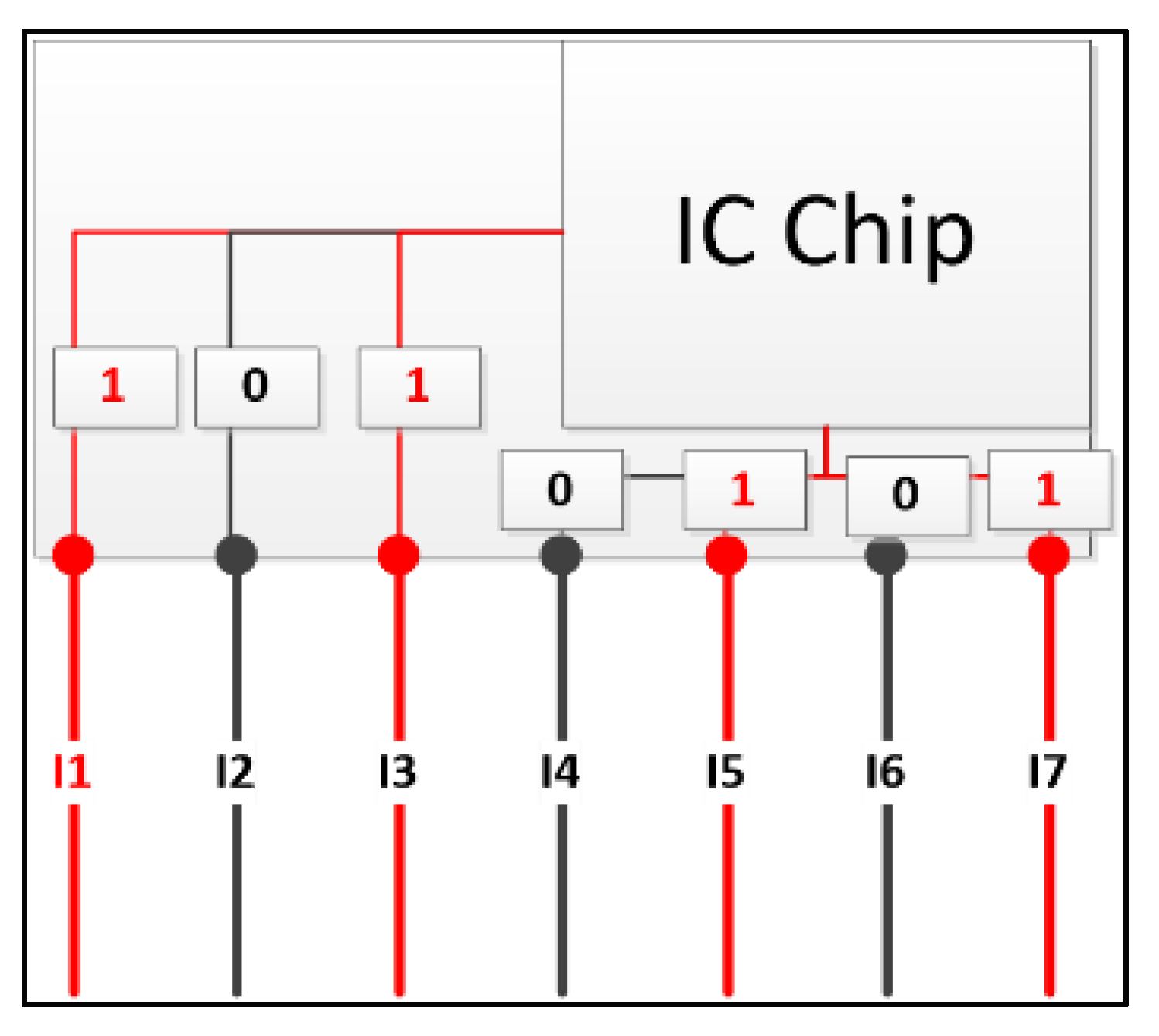
To receive MAC Frames from end-terminals, MUXERs use their ingress ports with RJ-45 form to guarantee them can receive data signals fully from end-terminals. When MUXERs are receiving data signals from end-terminals, their ingress ports also recognize if there are signals coming them, and they send a flag bit to IC Chip to notify that there are data signals on these ports.
Figure 4 shows the way that MUXER receives the data signals at ingress ports from end-terminals and notify to IC Chip. This process is simple. When end-terminals send data signals to ingress ports of MUXER, each ingress port which is received the data signals set its flag bit is one, and the other ports set their flag bits to zero, and send these bits to IC chip. So, IC chip can calculate how many ports are active (it means these ports are receiving data signals from end-terminals) to use for next actions.
3.4.2. MUXER and Switches
A MUXER can handle one switch or a group of switches. Communications between MUXER and switches are the main functions of MUXERs. In here, we divide them in four flows: Transferring data signals to switches in normal conditions (4.B1), turning off switches (4.B2), switching data signals from a switch to other switches in the group that are handled by MUXER (4.B3), and turning on switches (4.B4).
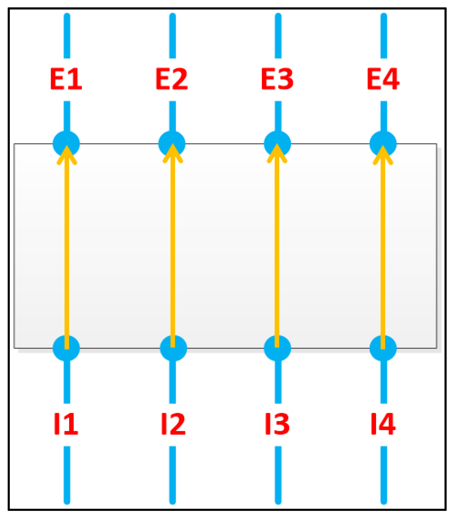
In case of 4.B1, data signals are sent to ingress ports of MUXER and are transmitted directly to correspondence egress ports. As described in Figure 5, egress port E1 is correspondence with ingress port I1, and (I2, E2), (I3, E3), (I4, E4) are similar. When MAC frames come to I1, I2, I3, I4, they are forwarded to E1, E2, E3, and E4.
In case of 4.B2, turning off switches actions must be satisfied with some conditions to guarantee the stability of network topologies, and the minimum probability of loss frames. The first condition is that MUXER must check if there are some data signals come to its ingress ports. As described in Section 4, when data signals come into MUXER’s ingress ports, ingress ports Ii set their flag bits Fi is one and send these bits to IC Chip. IC Chip receives these bits and uses its counter to count the total data signals for each switch that come to MUXER. After defined several times, with these flag bits, IC chip recognizes which switches don’t receive data signals or they receive a number of data signals that are smaller than a defined threshold to satisfy the first condition for generating turning off switches.
After MUXER can determine which switches are turned off, it has to check other switches in the group that it is handling if these switches can receive more data signals from others. To guarantee the simplicity of MUXER, in this paper, we base on the number of inactive ingress ports. If the number of inactive ingress ports of other switches that are handled by MUXER is larger than a defined threshold, it means MUXER can switch data signals to these switches. This process is also performed at IC Chip. IC chip checks the flag bits of its ingress ports that are correspondence with each switches.
When MUXER recognizes that two above conditions are satisfied, MUXER starts its counter to count down the time for generating turning off signal to switches. At this time, if there are no data signals that come to ingress ports of switches or the time is counted to zero, IC chip of MUXER generates a turn-off signal to its correspondence power port with a switch that is turned off. Power port propagates these signals to the power functions of switches and interrupt the power lines that are supplied for switches. The action flow is described detail in Figure 6 and Figure 7.
In case of 4.B3, IC chip of MUXER must have a mechanism to switch data signals from a switch to other switches. A requirement for this mechanism is simplicity.
Our approach is based on the electrical mechanism to switch physical circuits. In Figure 8a, in normal conditions, there are the physical circuits between I1 and E1, I2 and E2, I3 and E3, I4 and E4, but when in low traffic conditions, as Figure 8b, switch 1 is turned off, and the physical circuits between I1 and E1, I2 and E2 are dropped, and I1 is connected to E3, I2 is connected to E4.
To do that, our research proposes a simple mechanism. Each ingress port has a main circuit to its correspondence egress port. Otherwise, each ingress port also has its additional circuits to other egress ports, so that when an IC chip of MUXER want to switch data signals to any egress port of other switches, IC chip generates control signal to interrupt the main circuit or current circuit of that ingress port, and it generates the control signals to close the circuit of that ingress port and the egress port that MUXER want to transmit data signals of the ingress port to it.
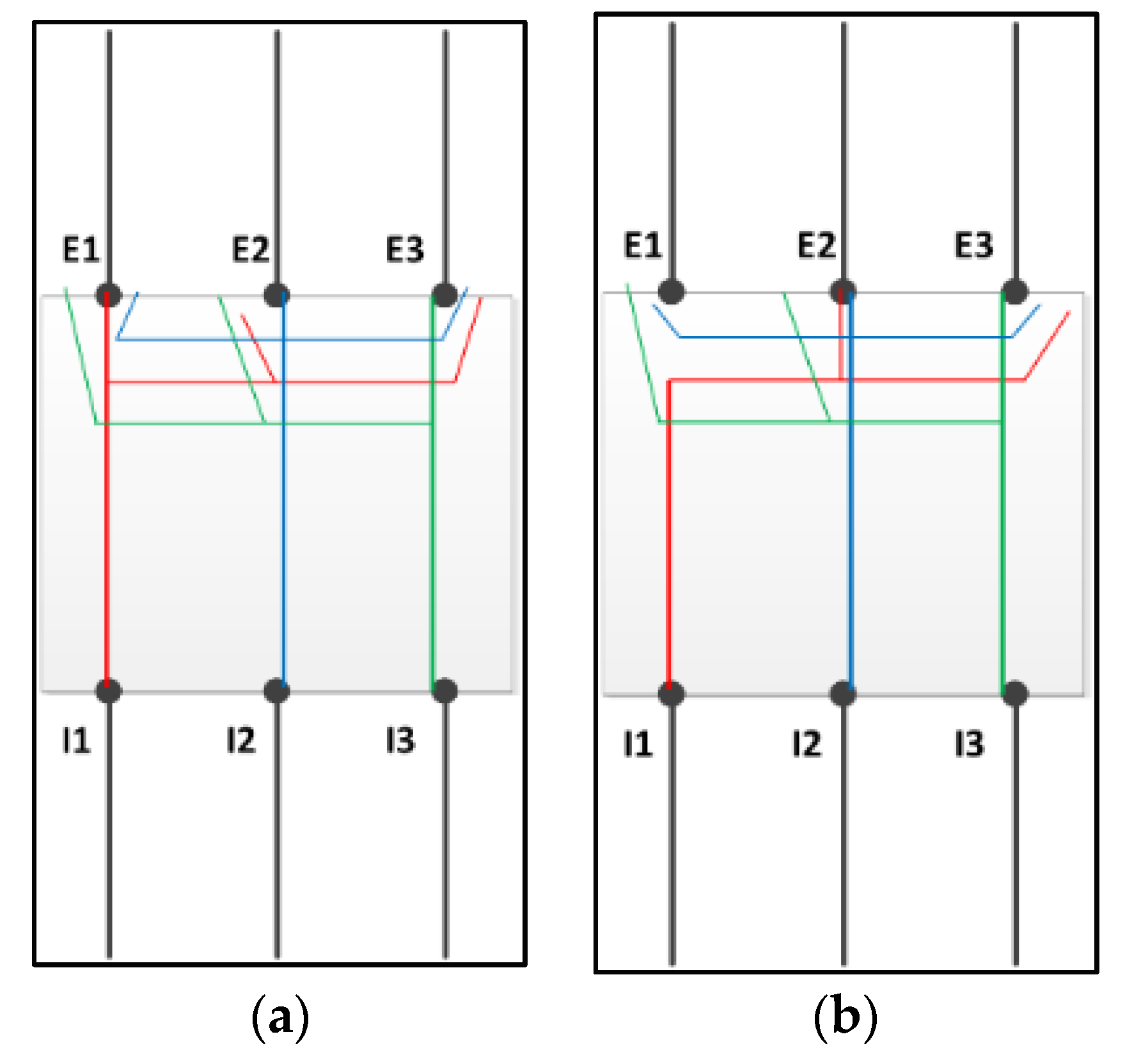
Figure 9 provides an example of this mechanism, (I1, E1) is the ports that is connected to switch S1, and (I2, E2), (I3, E3) are also belong to another switch S2. In Figure 9a, I1 is connected with E1, I2 is connected with E2, and I3 is connected with E3. After that, if MUXER turned off switch S1, it interrupted the main circuit of I1 to E1, and it opens the connected of another circuit from I1 to E2, which is described in Figure 9b. In case of I2, I3, if MUXER wants to change their connections to S1, its actions which are performed on I2, I3 are also same with I1.
In case of 4.B4, MUXER controls the power functions of the switches in a group that it is handling, hence MUXER must have a function to turn on the turned-off switch when the network environment return to normal status or high loading traffic.
There is one condition to turn on the switches that MUXER is controlling. That is the number of data signals that come to MUXER must be larger than a defined threshold. In here, it means the number of ingress ports are receiving data signals.
After MUXER recognizes that the above condition is satisfied, MUXER generates turn-on control signals to its correspondence power ports. In the similar way with the flow that turns off switches, power control port transmits power control signals to power functions of switches, and wakes up them.
3.4.3. MUXER and MUXER
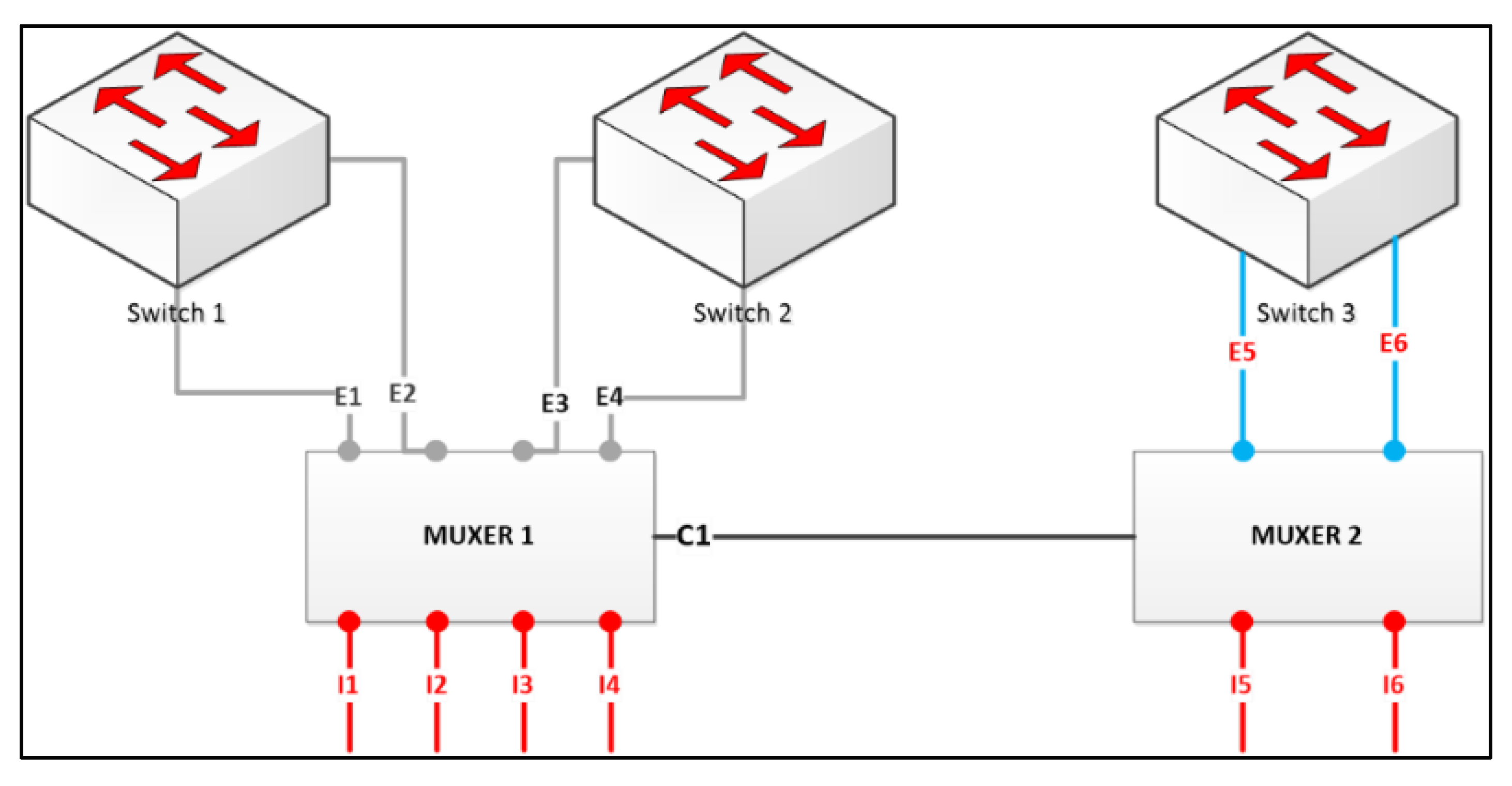
The purpose of communication among MUXERs in network topology helps MUXERs can transfer data signals to another group that is handled by another MUXER in case all switches in the group don’t receive any data signal, MUXER determines to turn off those switches, and want to find one of its neighbor MUXERs to transfer data signals whenever there are data signals coming the ingress ports of MUXER. In this relationship, there are two activities: checking status of MUXER’s neighbors periodically and checking the capacity of switches of neighbor MUXERs. These actions guarantee MUXER can transfer data signals continuously although all its switches are turned off. To do this, this paper uses control signal ports to communicate among MUXERs. In Figure 10, the control signal port is C1.
3.5. MUXER in a Nutshell
A MUXER includes five components: ingress ports, egress ports, data signal and control signal ports, power control ports, IC chip. Ingress ports are used to connect MUXER(s) with the end-terminals or the child network devices. Egress ports are used for transfer data signals, so they should be in RJ-45 form. The role of these ports is used to transmit signals that come to MUXER(s) to right network devices. Data signal ports are used to transmit data signals from MUXER to MUXER(s), while control signal ports transfer control signals between them. For easy understanding, we can build them on logical implementation with two types of RJ-45 port. One type is used to transfer data signals, and another type is used to exchange control signals. IC Chip is the most important component in MUXER. Its role is as the center of MUXER, which determines and generates all control signals and sends them to correspondence components. MUXER can receive the data signals from end-terminals, and determine which actions will be performed later. It can turn on the devices or turn off the devices, it can also just transfer data signals. More than one of this device can also be added. Ultimate goal of this device is to reduce the power consumption of network equipment.
4. Results
In this section, the paper makes a comparison about the power consumption in low-traffic condition between a normal LAN without MUXER (model 1) and another LAN within some MUXERs (model 2). Each model includes k routers, n switches and p end-terminals. The model 2 which contains MUXERs has q MUXERs (q ≤ n) with k ingress ports in each MUXER, and each MUXERs controls some switches and end-terminals which connected to these switches in normal LAN. To visualize the result, this paper uses a network of a university campus with 10 buildings. Each building has several floors. In here, we assume the number of floor of the campus is 73 floors, and the average number of 8-port switch in each floor are 8 switches. It means this paper analyzes the power consumption of 584 switches.
Each switch has four components which consume the powers: chassis, switching fabric, line-cards and ports. The chassis includes the cooling equipment, among other things, and its power consumption is denoted as Ps-fixed. The switching fabric is responsible for learning and maintaining the switching tables, and its power consumption is denoted as Pfabric. The line-cards maintain buffers for storing packets. Each switch has the finite buffer, and is denoted as Kbuffer. The power consumption of line-cards are denoted by Pline-card. Every port also consumes the power, each of them is denoted by Pport. We uses the values for Ps-fixed, Pfabric, Pline-card, and Pport from Cisco Power Calculator [18], and assume that the power consumed by this switch is indicative and typical of similar product (Table 2).
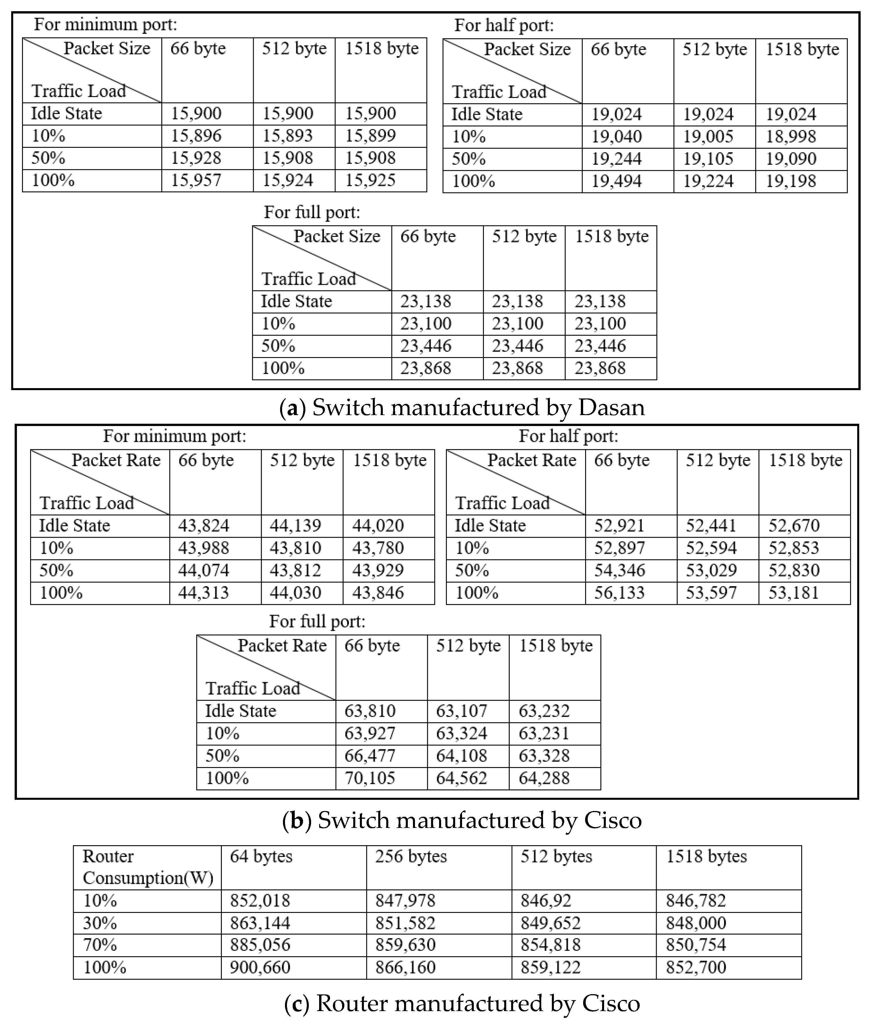
We experimented the power consumption rate with the switch and Router from different manufacturer for deciding our load model. Dasan (V2624G-PoEK, DASAN Networks, Inc., Seongnam-si, Gyeonggi-do, Korea) (56 Gbps/30 W) switch was tested with Wattman power meter (HPM-300A, AD POWER Co., Ltd., Bucheon-si, Gyeonggi-do, Korea) and Yokogawa WT210 (760401 model, Yokogawa Co., Ltd., Japan) measurement equipment, result is in Figure 11a.Cisco (WS-C3560G-24TS-S, Cisco Systems, Inc., San Jose, CA, USA) (32 Gbps/74 W) switch was tested with Yokogawa WT210 (760401 model, Yokogawa Co., Ltd., Tokyo, Japan) equipment and result given in Figure 11b. In both cases User Datagram Protocol (UDP) packets were collected for this experiment. CISCO 7609 router (OSR-7609, Cisco Systems, Inc., San Jose, CA, USA) (720 Gbps) with got 1 router processor, 1 switch fabric, 1 power supply and 2 line cards was used and tested with HPM-300A device (HPM-300A, AD POWER Co., Ltd., Bucheon-si, Gyeonggi-do, Korea) and result given in Figure 11c. In this router, Agilent Technologies N2X (Agilent N2X, Agilent Technologies, Inc., Santa Clara, CA, USA), IxN2X 7.40 GA Release with static routing protocol was used. Detail result of this router’s power consumption are given in Figure 11c. A portion of the complete result is stated here and we also collected data with other devices and packet type. At the same time, we experimented removing line card, all those data leading us that power consumption of tested equipment are linear.
Each MUXER has some components which consume the powers: IC Chip, ports, switching fabric. They are as denoted in Table 2 as Pic-chip, Pm-fixed.
Because each port of the switch has only one Kbuffer to store and to process ordered MAC Frames, this paper uses the M/M/1/K*FCFS queue (Kendall’s notation for queuing models) to model the rate of MAC Frame generated and came to the ports of switches or MUXERs. In this model, the request arrives according to a Poisson process with arrival rate λ and number of services with rate µ. The request will be blocked if the switch’s buffer has been reached to Kbuffer.
In this paper, we assume each port of switch has the same buffer capacity Kbuffer (bytes), each MAC frame that comes to its switch has the same size Sframe (bytes). With the M/M/1/K*FCFS [36], the probability when there are m MAC frames in the queue of each port is denoted as:
where, K = Kbuffer, S = Sframe, m ∈ [0, …, K/S], = λ/μ.
The probability of overload buffer is happened when N = K/S. We have:
This paper analyzes two models in case of night time, which has low load traffic. In this case, MUXERs turn on IC Chips, and they act as the controllers to receive and to delivery MAC frame to the switches on which they are controlling. In these two cases, this paper brings a comparison between two models about the power consumption, where each model consumes in a time range t.
In other side, this paper uses some parameter values to run simulations to compare the difference between two models, with K = 512 KB, S = 850 bytes, each switch has 8 Fast Ethernet ports (100 Mbps).
Therefore, we have and .
In each switch, there are three power model types: power consumption of active ports Pport-active-s, power consumption of idle ports Pport-idle, and power consumption of switch utilization Pfixed-s. They are calculated as:
In each MUXER, there are also three power model types: power consumption of active ports Pport-active-m, power consumption of idle ports Pport-idle, and power consumption of MUXER utilization Pfixed-m. We have:
Equations (4) and (6) gives us the Total power consumption due to utilization of SWITCH (Pfixed-s) and Total power consumption due to utilization of MUXER (Pfixed-m) respectively, on the other hand Total power consumption of active port of SWITCH (Pport-active-s) and Total power consumption of active port of MUXER (Pport-active-m) is in Equations (3) and (5) respectively. The calculative values of these are given in the next paragraph.
By calculating all the values from Table 2 and equation, which we got from test environment, we have the value of Pport-active-s = 5 W, Pfixed-s = 424 W, Pport-active-m = 8 W, Pfixed-m = 130 W. In the low-traffic load environment, we assume that network utilization is about 30% [37,38], so these values are: Pport-active-s = 1.5 W, Pfixed-s = 127.2 W, Pport-active-m = 2.4 W, Pfixed-m = 39 W.
In low traffic condition, some ports of switches are in idle status while the other ports are activated to receive a small amount of arrival MAC frames. Model 2 shows a LAN network in which each MUXER can control one or some switches. In this case, using MUXER devices can turn off switches, transfer MAC frames between switches in same levels.
The total throughput at each port of switch in time t can be calculated as:
In model 1, there is no turned off switch, the ratio of total active ports and total ports in network is α, so total power consumption of this model in time t is:
where .
In model 2, this paper assumes that network only has θ*n number of turn-on switches, the arrival rate of MAC frames to a port of MUXER in time t is equal with model 1, and we have:
where
5. Discussion
From the data shown in Figure 11, we can observe the power consumption rate of network devices (minimum port, half port and full port) with states changing from idle state to three different percentage of traffic load like 10%, 50% and 100% directed us to follow linear model. For this work, along with our experimental device’s behavior, we followed the linear model, but since design architecture of network equipment are always changing, our model can mismatch with other work [40]. Still we inspired from few more recent relevant work (considered perfectly linear behavior with respect to load), [15,41,42,43] to have a conclusion that power consumption of network devices can considered as linear with respect to load, and decided to use that for the rest of our experimental calculations. Hopefully in future we will try our device MUXER in consideration with power load as non-linear.
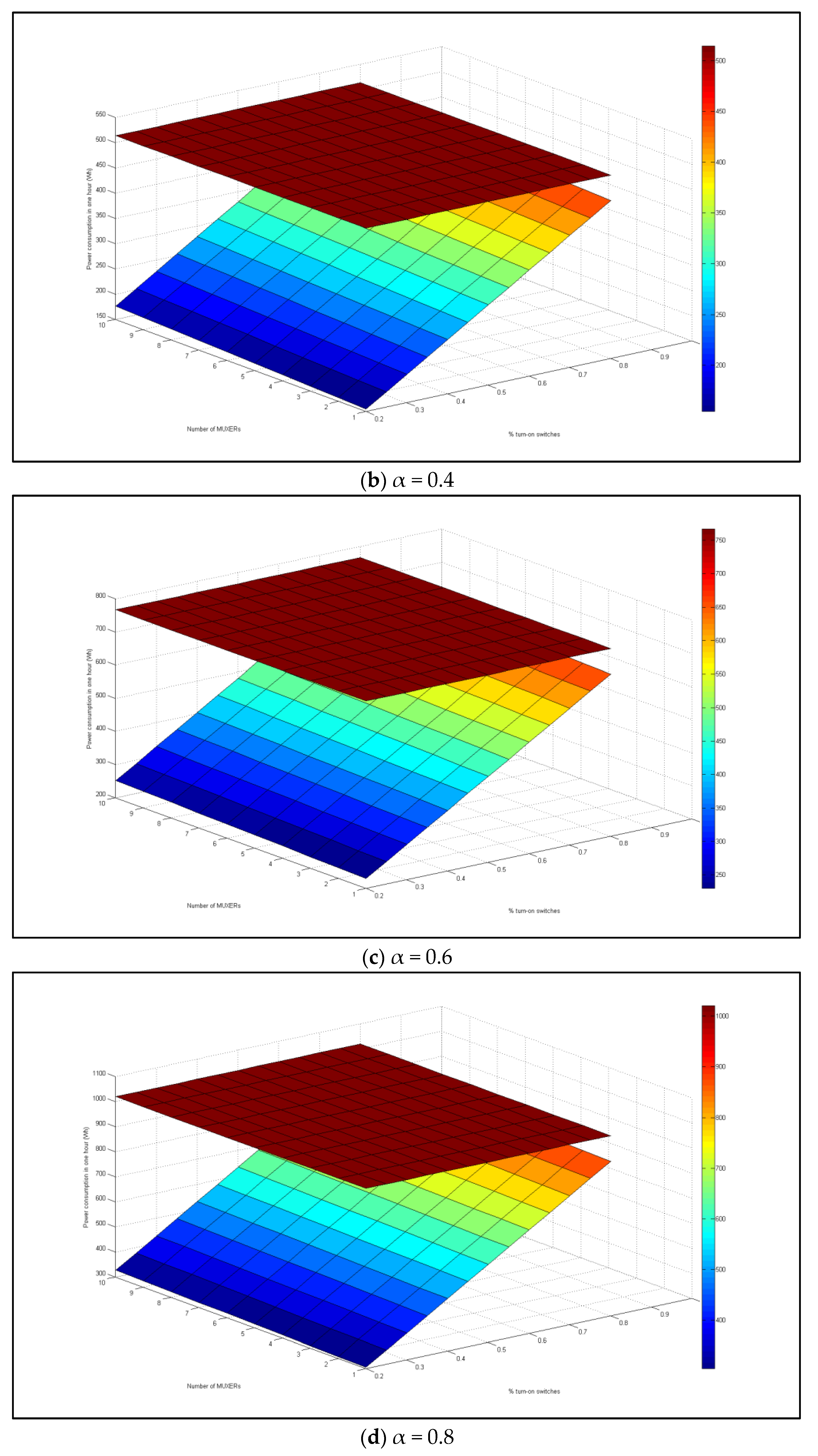
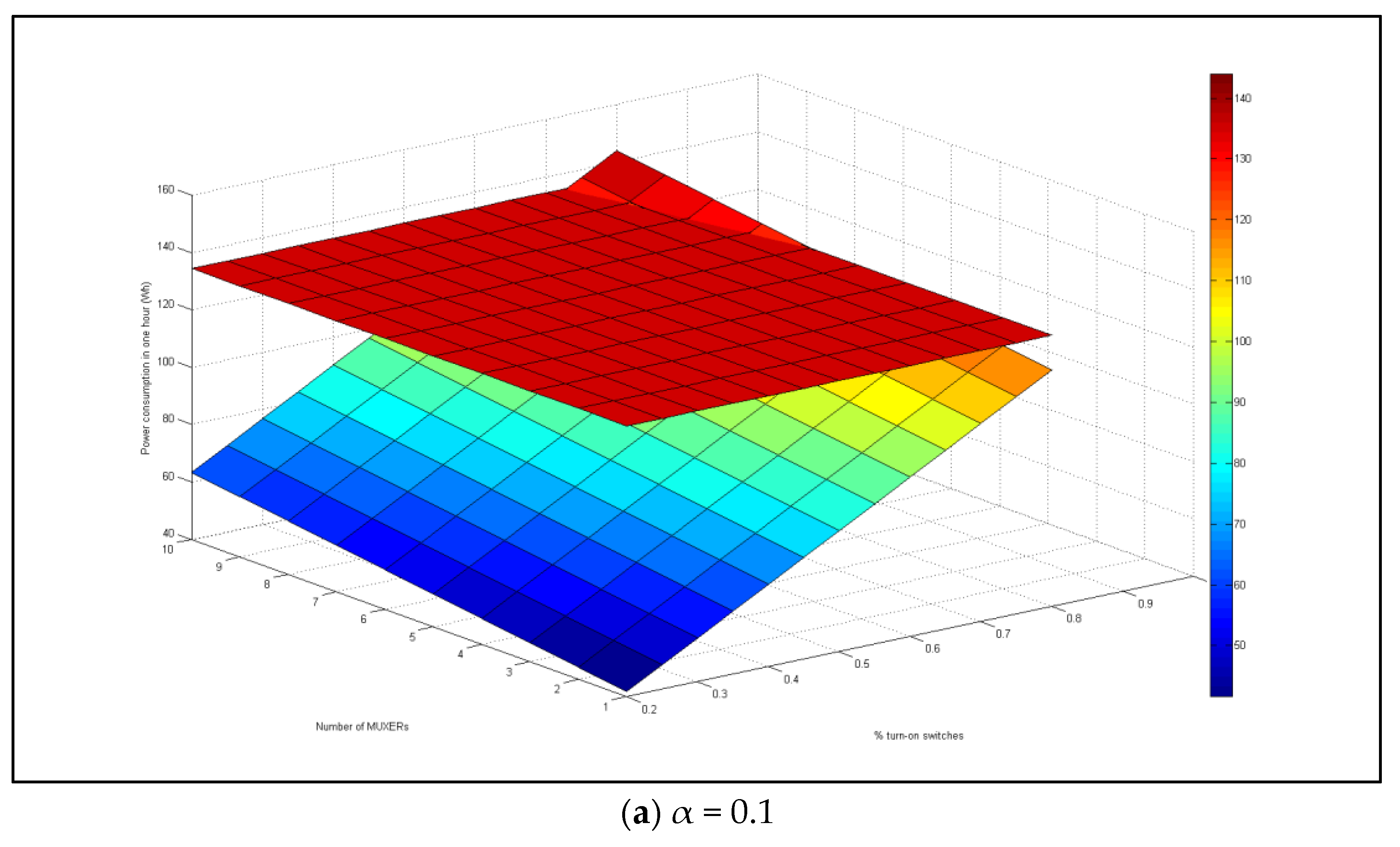
To have a conclusion about the effectiveness of model 2 when it is compared with model 1 in low-load traffic conditions, this paper considers on two cases: first, there are 584 switches in the network, and the percentage of the turn-on switches is increased from 20% to 80%; second, this paper considers a network with 10 switches in the network, and the percentage of the turn-on switches also is increased from 20% to 80%. In two cases, the ratio of the number of active switch’s ports are respectively 10%, 40%, 60%, and 80%.
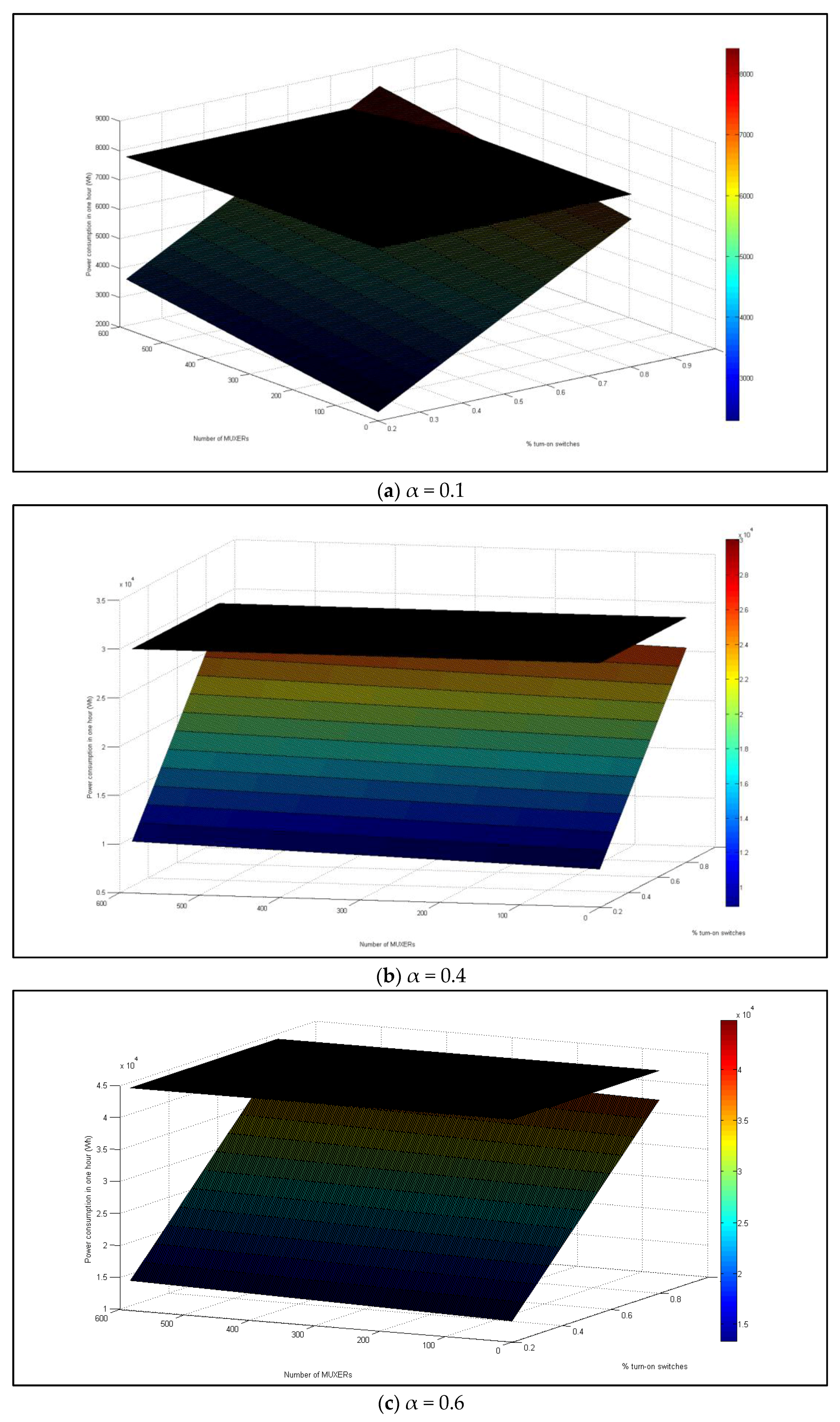
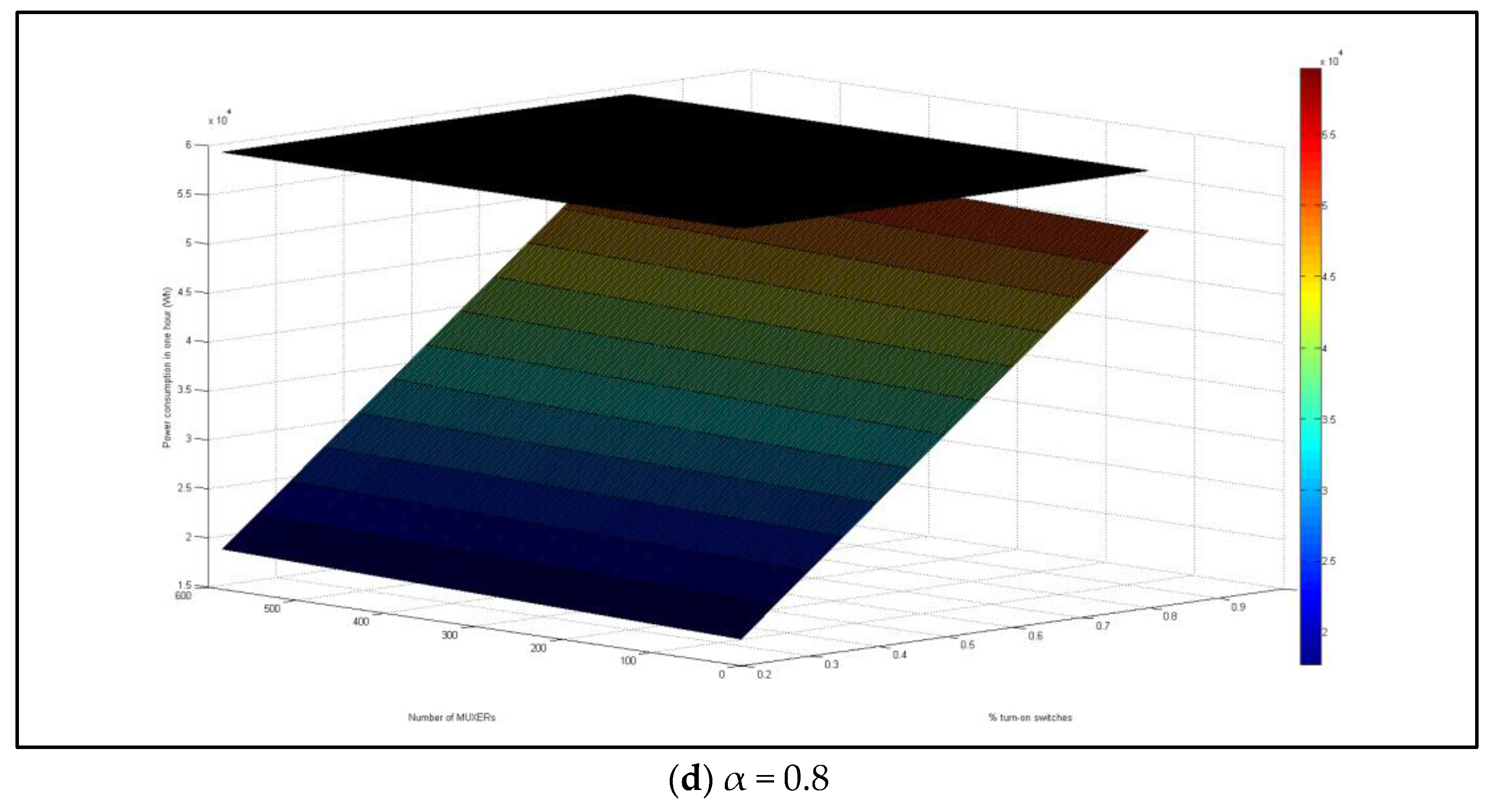
In the first case, Figure 12 shows the power consumption’s results of the two models. It shows the power consumption of model 1 is constant (black surface), while the values of model 2 are increased based on the number of turn-on switches and the number of MUXERs.
As the result of Figure 12, model 2 is only really more effective than model 1 when we use the suitable number of MUXERs in network which are correspondence with the current number of active switches’ ports in network. Otherwise, model 2 consumes more energy than model 1, especially when there is a few active switches’ ports in network, as shown in Figure 12a when the number of active switches’ ports in network are just 10%.
Figure 13 shows the results of the second case. In this case, for the small number of switches in network, if a network administrator puts an unreasonable number of MUXERs, the power consumption of model 2 also consumes more power than model 1 (Figure 13a). In both two cases, when we put the corresponding number of MUXERs with the number of turn-on switches in the network, the power consumption results in model 2 show more effectively than model 1. It means that network administrators must know clearly the statuses of their networks: when their network is in high traffic, normal traffic, and low traffic load conditions to decide the reasonable number of MUXERs need to be put in the networks.
6. Conclusions
An important challenge for modern and powerful network equipment is to reduce energy consumption. The Energy Efficient Ethernet (EEE) standard, approved by IEEE in 2010, implements low-level mechanisms to improve Ethernet energy efficiency. Such standards, however, will not adopt in practice until their effects on workload performance are well understood. Energy consumption by network equipment and network infrastructure has a vast negative impact on sustainability of energy resources, which should be controlled by improving their power management efficiency. Currently, different manufacturer has their own equipment for controlling energy uses, but they have many limitations. Still, the fact that they are not yet ready for extensive deployment are discussed in all these articles [44,45,46,47]. Therefore, MUXER has good future prospects. We will make our device more robust and efficient by considering heterogeneous property of network with its damage and replace issues in future. We must consider response time or latency of MUXER in our future work for different behavior of network and bandwidth.
In this paper, a new network equipment named MUXER for reducing power consumption of the network is proposed. MUXER is a simple device which is put before the switches in the network that can receive the traffic from end-terminal or other devices and forward them to correspondence switches. This proposed device can control one or more switches in the same level of network to perform the turn-on or turn-off power function of switches when network traffic is in high-load or low-load conditions. The effectiveness of our proposed device has been proved in the analysis and experiment results. When network administrator can measure and put the compatible amount of MUXERs in network, they can be a power efficient solution for network. Otherwise, they increase the total power consumption of network many times. In this paper, our proposed approach has just included some prototype components and some prototype functions. Future work focuses on how to define some real thresholds which are installed in MUXER, how to build some prototypes of MUXER, and to apply them to a real LAN network to have some improvements that can be made finished products. In the future, this approach can be applied to the bigger network architecture and big enterprise which has the potential to save a large amount of energy usage.
Acknowledgments
Authors thank Computer and Communication lab (C&C) members of Inje University for providing technical and financial support respectively. The authors especially thank Joe Jaehoon for helping us during the whole process of this work. This work was supported from the yearly research fund from Inje University, South Korea; Fund id: 0001200801000. Finally, the authors thank anonymous reviewers for their valuable review.
Author Contributions
Chul-Soo Kim conceived the idea. Md Mehedi Hassan Onik and Hung Phan Hoo performed the experiment and analyzed data. Md Mehedi Hassan Onik, Hung Phan Hoo, and Nasr-Al Zaben wrote the paper. Finally, revised and edited by Chul-Soo Kim and Md Mehedi Hassan Onik. All authors have read and approved the final manuscript.
Conflicts of Interest
The authors declare no conflict of interest.
References
- Urban, B.; Tiefenbeck, V.; Roth, K. Energy Consumption of Consumer Electronics in U.S. Homes in 2010; Final Report to the Consumer Electronics Association (CEA); Fraunhofer Center for Systainable Energy Systems: Boston, MA, USA, 2011. [Google Scholar]
- United States Energy Information Administration, Electric Power Monthly, Table 5.3, 2007. Available online: http://www.eia.doe.gov/cneaf/electricity/epm/epm_sum.html (accessed on 12 July 2017).
- US Department of Energy; the Environmental Protection Agency. Carbon Dioxide Emissions from the Generation of Electric Power in the United States, 2000. Available online: http://www.eia.doe.gov/cneaf/electricity/page/co2_report/co2report.html (accessed on 12 July 2017).
- Santitoro, R. Metro Ethernet Services—A Technical Overview; Metro Ethernet Forum: Los Angeles, CA, USA, 2003. [Google Scholar]
- Nordman, B.; Christensen, K. Reducing the Energy Consumption of Network Devices. IEEE Trans. Comput. 2008, 57, 448–461. [Google Scholar]
- Gunaratne, C.; Christensen, K.; Nordman, B. Managing Energy Consumption Costs in Desktop PCs and LAN Switches with Proxying, Split TCP Connections, and Scaling of Link Speed. Int. J. Netw. Manag. 2005, 15, 297–310. [Google Scholar] [CrossRef]
- Kliazovich, D.; Bouvry, P.; Khan, S.U. GreenCloud: A packetlevel simulator of energy-aware cloud computing data centers. J. Supercomput. 2012, 62, 1263–1283. [Google Scholar] [CrossRef]
- Mahadevan, P.; Sharma, P.; Banerjee, S.; Ranganathan, P. Energy aware network operations. In Proceedings of the IEEE INFOCOM Workshops, Rio de Janeiro, Brazil, 19–25 April 2009; pp. 1–6. [Google Scholar]
- Christensen, K.; Reviriego, P.; Nordman, B.; Bennett, M.; Mostowfi, M.; Maestro, J.A. IEEE 802.3az: The road to energy efficient Ethernet. IEEE Commun. Mag. 2010, 48, 50–56. [Google Scholar] [CrossRef]
- Broadcom at Interop: Energy Efficient Ethernet is Good for the Planet. Available online: http://www.broadcom.com/blog/network-infrastructure/broadcom-at-interopenergy efficient-ethernet-is-good-for-the-planet/ (accessed on 12 October 2017).
- Cisco Systems; Intel Corporation. IEEE 802.3az Energy Efficient Ethernet: Build Greener Networks; Cisco Systems: San Jose, CA, USA, 2011. [Google Scholar]
- Yamaha. Disabling Energy Efficient Ethernet (EEE). Available online: http://www.yamahaproaudio.com/global/en/training_support/selftraining/dante_guide/chapter2/02_ee/ (accessed on 12 October 2017).
- Dell. Resolving Issues with Energy Efficient Ethernet (EEE) or Green Ethernet. Available online: http://www.dell.com/support/Article/us/en/19/421774/EN (accessed on 12 October 2017).
- Publication: More Data, Less Energy, Iea.org, 2017. Available online: http://www.iea.org/publications/freepublications/publication/more-data-less-energy.html (accessed on 12 October 2017).
- Hossain, M.M.; Rondeau, E.; Georges, J.P.; Bastogne, T. Modeling the power consumption of Ethernet switch. In Proceedings of the International SEEDS Conference 2015: Sustainable Ecological Engineering Design for Society, Leeds, UK, 17–18 September 2015. [Google Scholar]
- Spurgeon, C.E. Ethernet: The Definitive Guide; O’Reilly: Sebastopol, CA, USA, 2000. [Google Scholar]
- Decotignie, J.-D. Ethernet-based real-time and industrial communications. Proc. IEEE 2005, 93, 1102–1117. [Google Scholar] [CrossRef]
- Cisco, Cisco Power Calculator. Available online: http://tools.cisco.com/cpc/launch.jsp (accessed on 30 May 2017).
- Christensen, K.; Nordman, B.; Brown, R. Power management in networked devices. Computer 2004, 37, 91–93. [Google Scholar] [CrossRef]
- Rivoire, S.; Shah, M.; Ranganathan, P.; Kozyrakis, C.; Meza, J. Modeling and Metrology Challenges for Enterprise Power Management. IEEE Comput. 2007, 40, 39–48. [Google Scholar] [CrossRef]
- Fithritama, A.; Rondeau, E.; Bombardier, V.; Georges, J.P. Modeling fuzzy rules for managing power consumption of ethernet switch. In Proceedings of the IEEE 23rd International Conference on Software, Telecommunications and Computer Networks (SoftCOM), Split, Croatia, 16–18 September 2015; pp. 42–47. [Google Scholar]
- Gupta, M.; Grover, S.; Singh, S. A feasibility study for power management in LAN switches. In Proceedings of the 12th IEEE International Conference on Network Protocols, Berlin, Germany, 8 October 2004; pp. 361–371. [Google Scholar]
- Mahadevan, P.; Shah, A.; Bash, C. Reducing lifecycle energy use of network switches. In Proceedings of the IEEE International Symposium on Sustainable Systems and Technology (ISSST), Arlington, VA, USA, 17–19 May 2010; pp. 1–6. [Google Scholar]
- Nedevschi, S.; Popa, L.; Iannaccone, G.; Ratnasamy, S.; Wetherall, D. Reducing Network Energy Consumption via Sleeping and Rate-Adaptation. In Proceedings of the 5th USENIX Symposium on Networked Systems Design and Implementation, San Francisco, CA, USA, 16–18 April 2008; Volume 8, pp. 323–336. [Google Scholar]
- Reviriego, P.; Christensen, K.; Rabanillo, J.; Maestro, J.A. An Initial Evaluation of Energy Efficient Ethernet. IEEE Commun. Lett. 2011, 15, 578–580. [Google Scholar] [CrossRef]
- Herreria-Alonso, S.; Rodriguez-Perez, M.; Fernandez-Veiga, M.; Lopez-Garcia, C. A GI/G/1 Model for 10 Gb/s Energy Efficient Ethernet Links. IEEE Trans. Commun. 2012, 60, 3386–3395. [Google Scholar] [CrossRef]
- Larrabeiti, D.; Reviriego, P.; Hernandez, J.; Maestro, J.; Uruena, M. Towards an energy efficient 10 Gb/s optical ethernet: Performance analysis and viability. Opt. Switch. Netw. 2011, 8, 131–138. [Google Scholar] [CrossRef] [Green Version]
- Cenedese, A.; Tramarin, F.; Vitturi, S. An Energy Efficient Ethernet Strategy Based on Traffic Prediction and Shaping. IEEE Trans. Commun. 2017, 65, 270–282. [Google Scholar] [CrossRef]
- Chakraborty, D.; Ashir, A.; Suganuma, T.; Keeni, G.M.; Roy, T.K.; Shiratori, N. Self-similar and fractal nature of Internet traffic. Int. J. Netw. Manag. 2004, 14, 119–129. [Google Scholar] [CrossRef]
- Vitturi, S.; Tramarin, F. Energy efficient Ethernet for real-time industrial networks. IEEE Trans. Autom. Sci. Eng. 2015, 12, 228–237. [Google Scholar] [CrossRef]
- Cenedese, A.; Michielan, M.; Tramarin, F.; Vitturi, S. An energy efficient traffic shaping algorithm for Ethernet-based multimedia industrial traffic. In Proceedings of the IEEE Emerging Technology Factory Autom (ETFA), Barcelona, Spain, 16–19 September 2014; pp. 1–4. [Google Scholar]
- Zhang, B.; Sabhanatarajan, K.; Gordon-Ross, A.; George, A. Realtime performance analysis of adaptive link rate. In Proceedings of the 33rd IEEE Conference on Local Computer Networks (LCN), Montreal, QC, Canada, 14–17 October 2008; pp. 282–288. [Google Scholar]
- Gunaratne, C.; Christensen, K.; Suen, S.W. Ethernet adaptive link rate (ALR): Analysis of a buffer threshold policy. In Proceedings of the IEEE Globecom, San Francisco, CA, USA, 27 November–1 December 2006; pp. 1–6. [Google Scholar]
- Gunaratne, C.; Christensen, K.; Suen, S.W.; Nordman, B. Reducing energy consumption of Ethernet with an adaptive link rate (ALR). IEEE Trans. Comput. 2008, 57, 448–461. [Google Scholar] [CrossRef]
- IEEE Std. 802.3az. IEEE Standard for Information Technology—Local and Metropolitan Area Networks; IEEE: Washington, DC, USA, 2010. [Google Scholar]
- Kleinrock, L. Queueing Systems, Volume 2: Computer Applications; Wiley: New York, NY, USA, 1976; Volume 66. [Google Scholar]
- Odlyzko, A. The Internet and Other Networks: Utilization Rates and Their Implications (1 September 1998). Inf. Econ. Policy 2000, 12, 341–365. [Google Scholar] [CrossRef]
- Odlyzko, A. Data networks are lightly utilized, and will stay that way. Rev. Netw. Econ. 2003, 2. [Google Scholar] [CrossRef]
- Kendall, D.G. Stochastic processes occurring in the theory of queues and their analysis by the method of the imbedded Markov chain. Ann. Math. Stat. 1953, 24, 338–354. [Google Scholar] [CrossRef]
- Barroso, L.; Holzle, U. The case of energy proportional computing. ACM Comput. J. 2007, 40. [Google Scholar] [CrossRef]
- Mahadevan, P.; Sharma, P.; Banerjee, S.; Ranganathan, P. A Power Benchmarking Framework for Network Devices. In Proceedings of the 8th International IFIP-TC 6 Networking Conference, Aachen, Germany, 11–15 May 2009; pp. 795–808. [Google Scholar]
- Ye, T.T.; Benini, L.; De Micheli, G. Analysis of power consumption on switch fabrics in network routers. In Proceedings of the 39th annual Design Automation Conference (IEEE Cat. No. 02CH37324), New Orleans, LA, USA, 10–14 June 2002; pp. 524–529. [Google Scholar]
- Restrepo, C.; Gruber, C.G.; Machuca, C.M. Energy Profile Aware Routing; IEEE: Munich, Germany, 2009. [Google Scholar]
- Disabling Energy Efficient Ethernet (EEE), Setting up Cisco SG300, Dante Network Design Guide, Self Training, Training & Support, Yamaha, Yamahaproaudio.com. 2017. Available online: http://www.yamahaproaudio.com/global/en/training_support/selftraining/dante_guide/chapter3/02_eee/ (accessed on 14 October 2017).
- Energy Efficient Ethernet (EEE)/Green Ethernet, Support.crestron.com. 2017. Available online: https://support.crestron.com/app/answers/detail/a_id/5764/~/energy-efficient-ethernet-%28eee%29-%2F-green-ethernet (accessed on 14 October 2017).
- What is IEEE 802.3az Energy Efficient Ethernet? Answer, NETGEAR Support, Kb.netgear.com. 2017. Available online: https://kb.netgear.com/31291/What-is-IEEE-802-3az-Energy-Efficient-Ethernet (accessed on 14 October 2017).
- Any Issues with EEE (Energy Efficient Ethernet) on a Arris 6190 Modem • r/Eero, Reddit. 2017. Available online: https://www.reddit.com/r/eero/comments/519qgo/any_issues_with_eee_energy_efficient_ethernet_on/ (accessed on 14 October 2017).
Figure 1.
Main processes of MUXER.

Figure 2.
Position of MUXER in network topology.

Figure 3.
Component of MUXER.
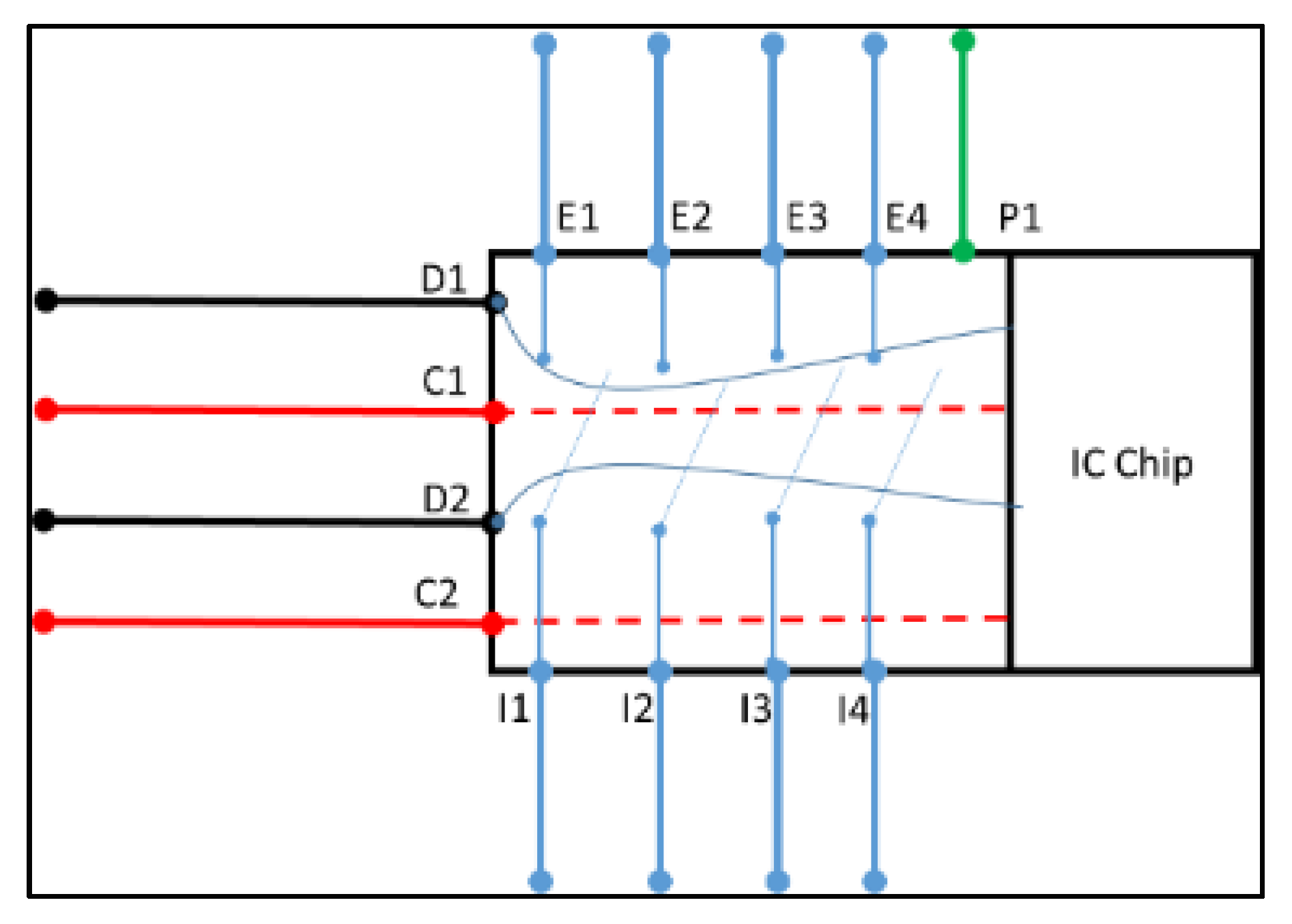
Figure 4.
Flow of data signals when they come to ingress ports of MUXER.

Figure 5.
MUXER in normal conditions.

Figure 6.
Mechanism of MUXER to turn off and turn on switch.
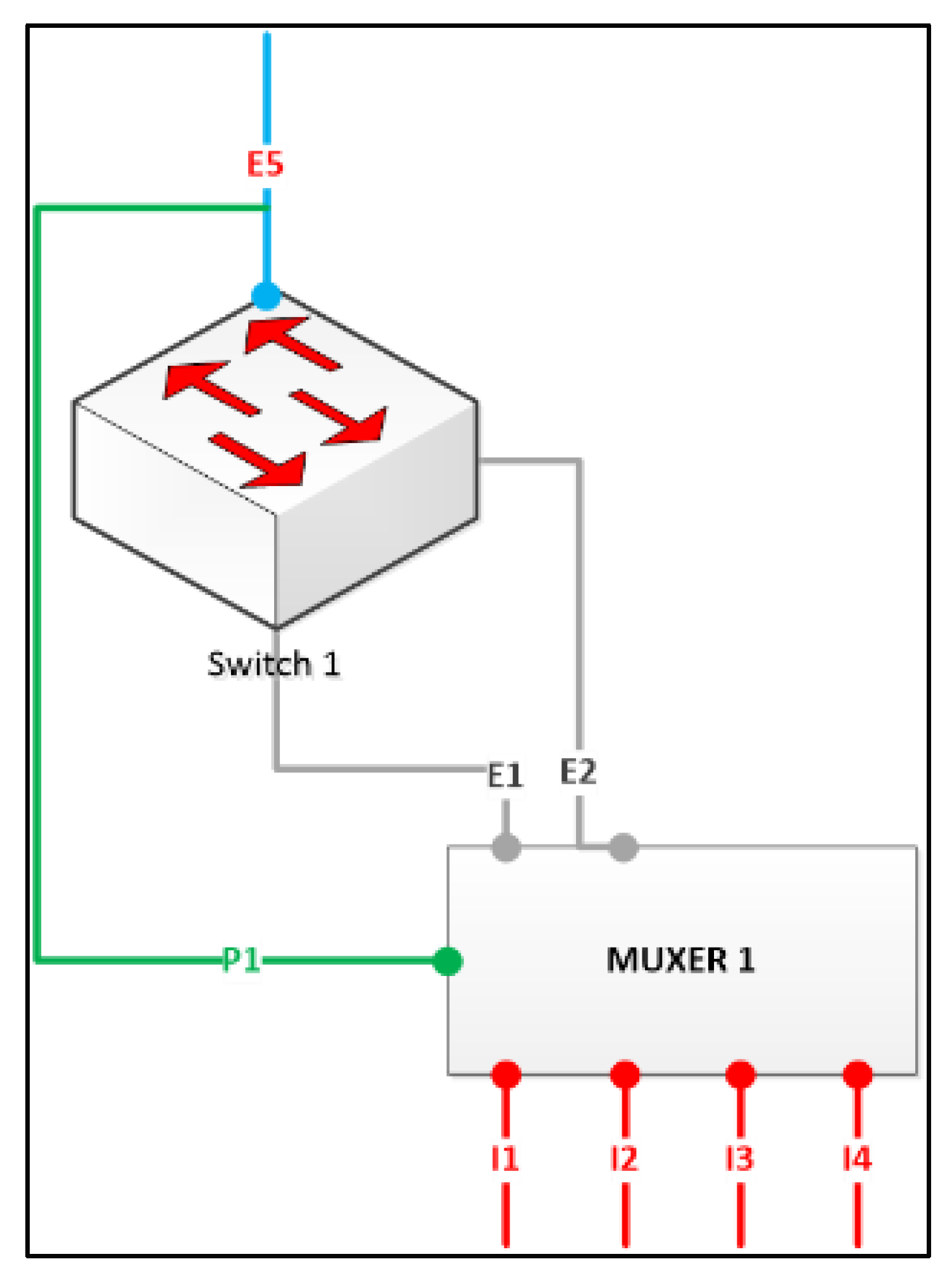
Figure 7.
Flow of MUXER to turn off switches.

Figure 8.
How MUXER can switch data signal from switch 1 to switch 2. (a) Before MUXER switches some circuits; (b) After MUXER switches some circuits.
Figure 8.
How MUXER can switch data signal from switch 1 to switch 2. (a) Before MUXER switches some circuits; (b) After MUXER switches some circuits.

Figure 9.
Structure of electricity circuits to switch data signals from an egress port to another egress port. (a) Switch S1 (I1 and E1) is in ON state; (b) MUXER turn of switch S1 (I1 and E1) and S1 goes in OFF state to open the connection of another circuit from I1 to E2 (no use of E1 now).
Figure 9.
Structure of electricity circuits to switch data signals from an egress port to another egress port. (a) Switch S1 (I1 and E1) is in ON state; (b) MUXER turn of switch S1 (I1 and E1) and S1 goes in OFF state to open the connection of another circuit from I1 to E2 (no use of E1 now).

Figure 10.
Communication among MUXERs.

Figure 11.
Power consumption results of network devices. (a) Switch of DASAN; (b) Switch of Cisco; (c) Router of Cisco.
Figure 11.
Power consumption results of network devices. (a) Switch of DASAN; (b) Switch of Cisco; (c) Router of Cisco.

Figure 12.
Power consumption results of model 1 and model 2 with n = 584 switches, and α = (0.1, 0.4, 0.6, 0.8). (a) α = 0.1; (b) α = 0.4; (c) α = 0.6; (d) α = 0.8.
Figure 12.
Power consumption results of model 1 and model 2 with n = 584 switches, and α = (0.1, 0.4, 0.6, 0.8). (a) α = 0.1; (b) α = 0.4; (c) α = 0.6; (d) α = 0.8.


Figure 13.
Power consumption of model 1 and model 2 with n = 10 switches, and α = (0.1, 0.4, 0.6, 0.8.) (a) α = 0.1; (b) α = 0.4; (c) α = 0.6; (d) α = 0.8.
Figure 13.
Power consumption of model 1 and model 2 with n = 10 switches, and α = (0.1, 0.4, 0.6, 0.8.) (a) α = 0.1; (b) α = 0.4; (c) α = 0.6; (d) α = 0.8.


Table 1.
Breakdown of energy draw of various networking devices (kWh refers to kilo-Watt hours and AEC refers to Annual Electricity Consumption).
Table 1.
Breakdown of energy draw of various networking devices (kWh refers to kilo-Watt hours and AEC refers to Annual Electricity Consumption).
| Device | Approximate Number Deployed (millions) | Total AEC (kWh/year) |
|---|---|---|
| Hubs/Switch | 0.6 | 29.7 |
| Wireless router | 46.2 | 42.4 |
| Wired-only router | 1.7 | 78.3 |
| Total/Avg | 48.5 | 43.5 |
Table 2.
Parameters are used in the models (Calculated with Cisco Power Calculator [18]).
Table 2.
Parameters are used in the models (Calculated with Cisco Power Calculator [18]).
| Parameter | Value (100%) | Value (30%) | Description |
|---|---|---|---|
| Ps-fixed | 60 W | 18 W | Power consumption of chassis of a switch |
| Pfabric | 315 W | 94.5 W | Power consumption of switching fabric of switch |
| Pline-card | 49 W | 14.7 W | Power consumption of line-cards of switch |
| Pport | 3 W | 0.9 W | Power consumption of different states of ports |
| Pport-idle | 0.1 W | 0.03 W | |
| Pport-transition | 2 W | 0.6 W | |
| Pport-transition (port-transition—Time) | 1 ms to 10 ms | 1 ms to 10 ms | |
| Pic-chip | 100 W | 30 W | Power consumption of IC Chip of MUXER |
| Pm-fixed | 30 W | 9 W | Power consumption of Ports of a MUXER |
© 2017 by the authors. Licensee MDPI, Basel, Switzerland. This article is an open access article distributed under the terms and conditions of the Creative Commons Attribution (CC BY) license (http://creativecommons.org/licenses/by/4.0/).
Share and Cite
MDPI and ACS Style
Onik, M.M.H.; Al-Zaben, N.; Phan Hoo, H.; Kim, C.-S. MUXER—A New Equipment for Energy Saving in Ethernet. Technologies 2017, 5, 74. https://doi.org/10.3390/technologies5040074
AMA Style
Onik MMH, Al-Zaben N, Phan Hoo H, Kim C-S. MUXER—A New Equipment for Energy Saving in Ethernet. Technologies. 2017; 5(4):74. https://doi.org/10.3390/technologies5040074
Chicago/Turabian StyleOnik, Md Mehedi Hassan, Nasr Al-Zaben, Hung Phan Hoo, and Chul-Soo Kim. 2017. "MUXER—A New Equipment for Energy Saving in Ethernet" Technologies 5, no. 4: 74. https://doi.org/10.3390/technologies5040074
Note that from the first issue of 2016, this journal uses article numbers instead of page numbers. See further details here.