
Railway Continuous Prestressed Concrete Bridge Design in Ballastless Track Turnout Zones


1
Southern Region Engineering Office, Railway Reconstruction Bureau, Ministry of Transportation and Communications, Kaohsiung 81354, Taiwan
2
Central Region Engineering Office, Railway Reconstruction Bureau, Ministry of Transportation and Communications, Taichung 40143, Taiwan
3
Department of Civil Engineering, Chung Hua University, Hsinchu 30012, Taiwan
*
Author to whom correspondence should be addressed.
Technologies 2017, 5(2), 11; https://doi.org/10.3390/technologies5020011
Submission received: 31 December 2016
/
Revised: 17 March 2017
/
Accepted: 23 March 2017
/
Published: 30 March 2017
(This article belongs to the Special Issue Construction Materials Technologies)
Abstract
:Laying ballastless track on railway bridges has the advantages of reducing the train noise problem, improving passenger comfort, and reducing track maintenance costs. Therefore, railway bridges with ballastless track have gradually turned into a major trend in railway systems all over the world. In Taiwan, railway bridges with ballastless track have been in use for many years, with ballastless track turnouts also starting to be constructed in recent years. Where railway bridges with ballastless track turnouts are located in urban areas, special consideration must be given to the road crossings and the use of continuous bridges in the turnout zones. Accordingly, there arise a number of difficulties related to the bridge configurations or the continuous length of bridges being excessively long. Often, such situations necessitate the use of extremely large-sized bridge piers in the bridge design, or create the risk of serious damage to the pier structure should insufficient attention be given to any of the factors. This article will take a continuous prestressed concrete bridge as an example. The prestressed concrete bridge must be absolutely continuous, be able to include ballastless track turnout zones, and meet the needs of crossing roads. For this example, the length of the continuous prestressed concrete bridge is over 300 m. This article will also discuss the configuration of a continuous prestressed concrete bridge of railway, and—through the analysis of track–bridge interaction and temperature detection—provides suggestions on the optimal configuration model of the continuous prestressed concrete bridges, which should allow improper configuration and possible structural damage to be avoided.
1. Introduction
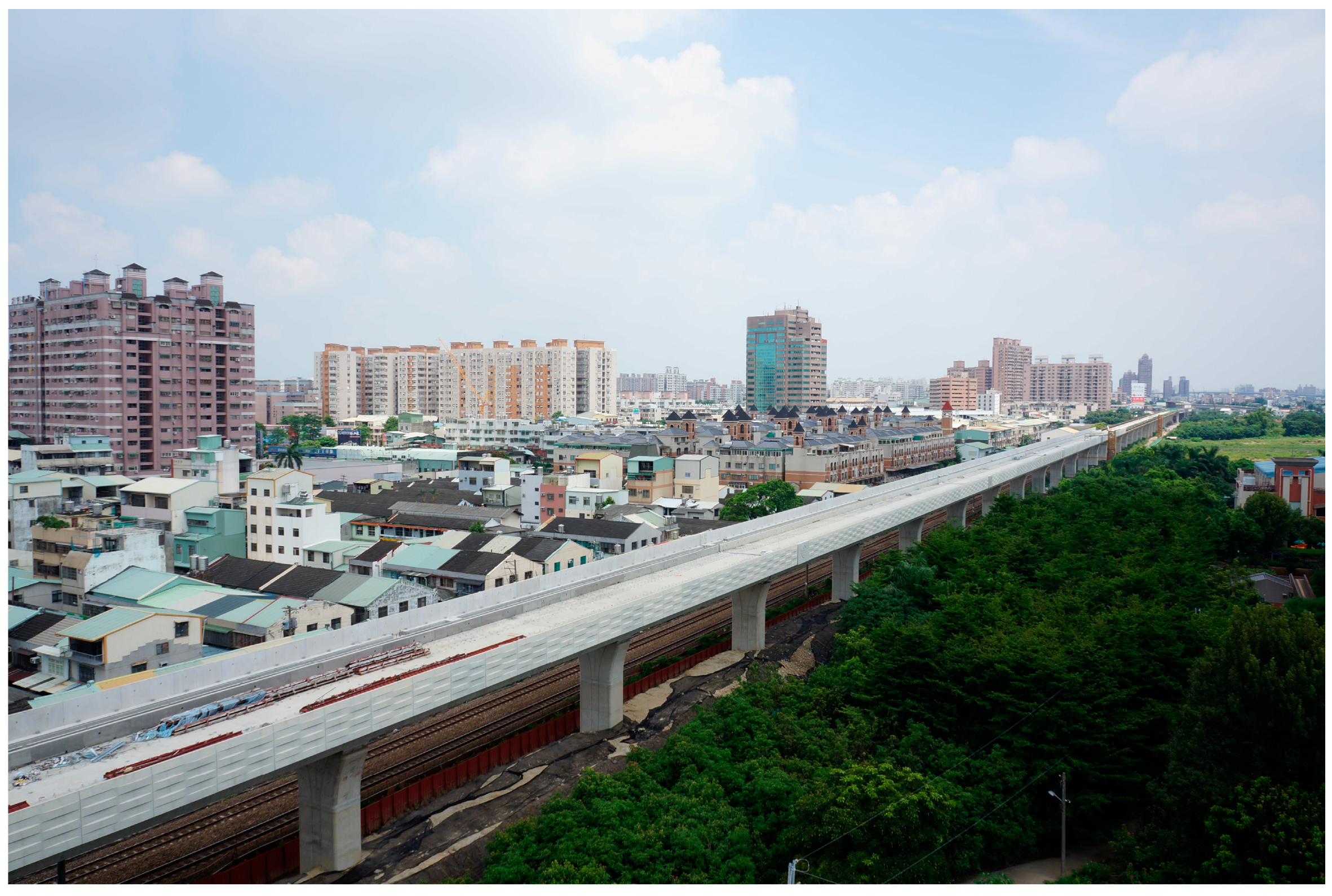
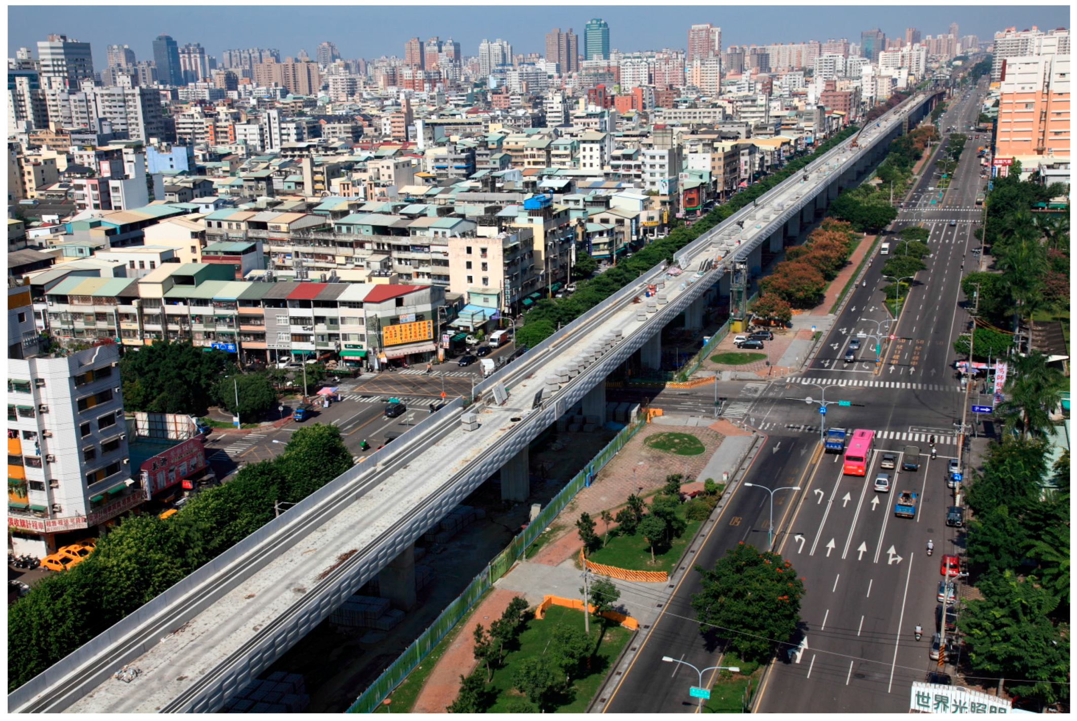
To effectively use urban land and address various urban transport problems, in recent years the government of Taiwan has been promoting the use of elevated railway systems in urban areas, as shown in Figure 1. Since most urban railways are located adjacent to densely-populated residential and commercial areas, noise and vibration reduction becomes an important issue after the commencement of railway viaduct operation. Laying ballastless track has become a basic need in railway viaduct projects due to the importance of train noise reduction, improvement of passenger comfort, and the need to minimize the track maintenance costs.
An elevated urban railway system usually contains general railway bridges, elevated railway stations, and turnout zone bridges at both ends of the elevated railway station. As previously mentioned, when configuring continuous prestressed concrete bridges, we must consider crossing roads and adopting continuous bridge in the turnout zone. This often leads to bridge span configuration issues and problems related to the bridge length being too long. These situations necessitate the use of very large-sized bridge piers in the railway bridge design, and create the risk of structural damage.
This article will therefore recommend solutions for continuous prestressed concrete bridge design in turnout zones, and continuous length over 300 m. It will suggest the configuration essentials of continuous prestressed concrete bridge design in turnout zones through an analysis of temperature changes and various types of bridge load. The article will also discuss the structural characteristics of continuous bridges, the effects of various loading types on continuous bridges, and will consider some important points on continuous bridge design which allow structure damage problems to be minimized.
2. Ballastless Track Turnout Layout Theory
2.1. Turnouts and Bridge Configuration
As the train speed increases, the viaduct railway with a ballastless track becomes an increasingly important factor in the safety and stability of railway operation, and the deformation requirements of ballastless track turnout structure become more and more stringent. Therefore, there are a number of strict rules and restrictions when it comes to the configuration of ballastless track turnouts on the railway viaduct.
2.1.1. Avoid the Bridge Expansion Joint on Ballastless Track Turnout Zone
Bridge expansion joints should not be installed in the railway viaduct’s ballastless track turnout zone, and continuous bridge configuration in the ballastless track turnout zone must conducted. If the configuration cannot be performed for the continuous bridge, design of the bridge expansion plate should contain a hinge at the bridge expansion joints in order to meet the requirement that the turnout zone must not be set up at the bridge expansion joints.
In addition, the relative displacement of a bridge expansion joint can cause track displacement or turnout damage, so the bridge expansion joint with turnout switch blades must be kept at a certain distance (denoted as “d” in Table 1 below). The d values are recommended in Table 1, in which L indicates the expansion length of the bridge [1].
For the bridge expansion length (L), the following larger values are required:
- (1)
- Bridge fixed point and movable support of simple span or multi-span bridge.
- (2)
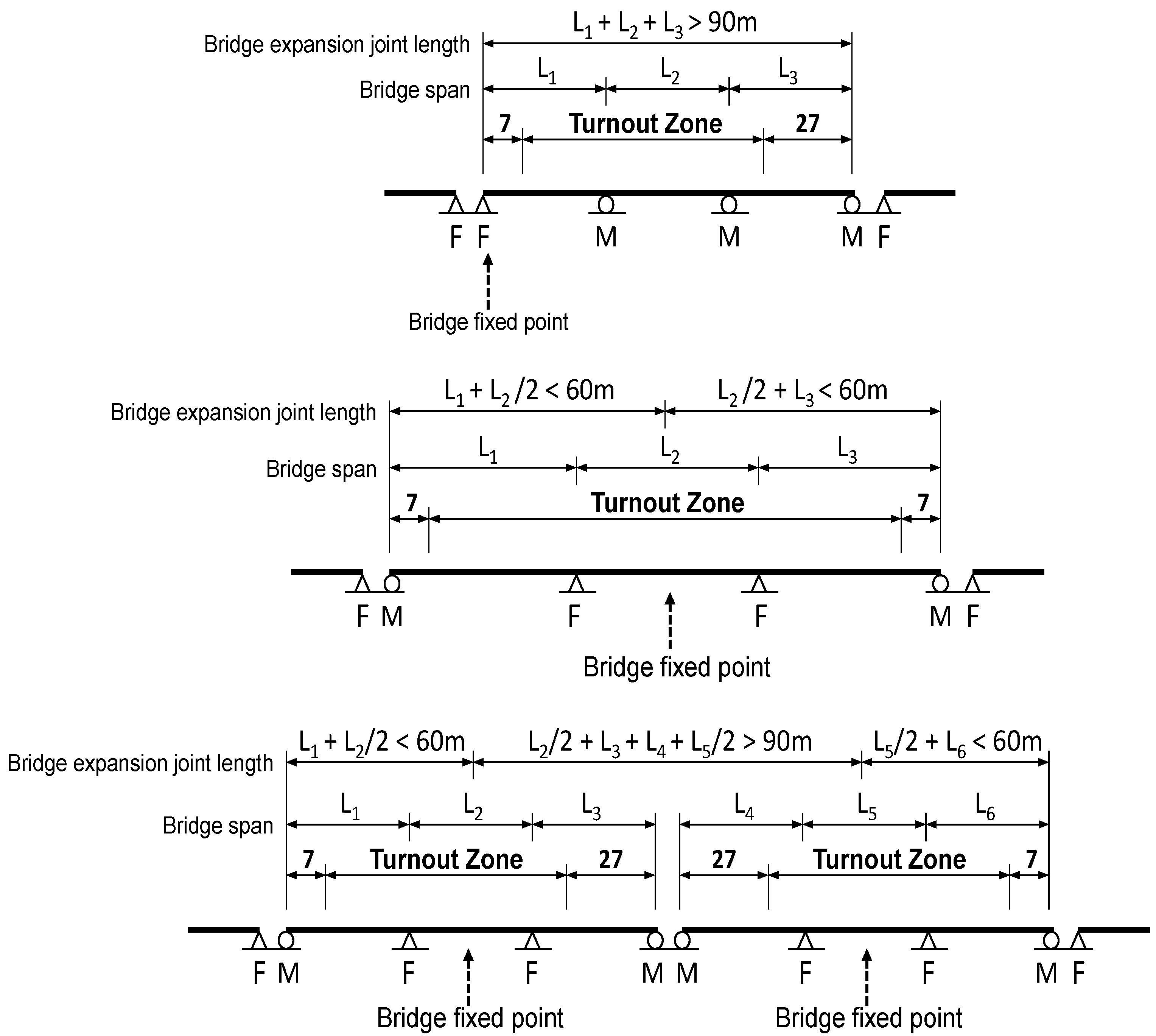
- The distance between two adjacent bridges of bridge fixed points. In short, a complex bridge type can be simplified to a simple beam model to determine the bridge expansion length L. The decision of a simple beam model depends on the main bridge structure subjected to axial deformation of temperature change. According to bridge axial deformation restraints, decide the fixed bearing positions and movable bearing positions, shown in Figure 2.
2.1.2. Avoid Configuring Continuous Long-Span Bridges
Usually, laying ballastless track is accompanied by the adoption of continuous welded rail. For continuous long-span bridges, it is easy to cause resistance to rail longitudinal accumulation force and exceed the allowable limits of the rail. So, configured continuous long-span bridges should be avoided in ballastless track turnout zone. If these cannot be avoided, the rails under high temperature axial force or the fractured openings at low temperature should be reviewed, and rail expansion joints must be set if necessary [2,3].
2.2. Effect of Temperature Difference between Bridge and Track System
For ballastless track turnout on a continuous prestressed concrete bridge, it should be remembered that changes of temperature, rails, and bridges may be restricted by boundary conditions. Due to the difference in the coefficients of thermal expansion of rails and bridges, track longitudinal forces are created between rails and bridges. For ballastless track, the strength of longitudinal force between rails and bridges is determined by the rail fastening clip. In addition, bridges produce contraction by temperature variation and the restraint of bridge supports. The interaction behavior between rails and bridges becomes complicated. It is important that tracks and bridge structures must be carefully configured in order to properly control rail axis forces along the track’s longitudinal direction to avoid rail buckling problems [4].
Accordingly, when laying ballastless track on railway bridges, the influence of track–bridge interaction must be carefully evaluated and reviewed, including the following aspects [5]:
- (1)
- Proper configuration of bridge supports and bridge spans.
- (2)
- Inspection of fixed support of bridge while continuous welded rails produce maximum longitudinal force.
- (3)
- Inspection of track buckling stability at maximum temperature.
- (4)
- Inspection of track fractured opening at minimum temperature.
- (5)
- The setting up requirements of rail expansion joints or protective device.
3. Continuous Prestressed Concrete Bridge Design in Ballastless Track Turnout Zone
3.1. Configuration of the Continuous Prestressed Concrete Bridges
The article takes a continuous prestressed concrete bridge as an example. The bridge configuration satisfies both the requirements of having street-level road crossings and of adopting an absolutely continuous bridge in the turnout zone conditions. Figure 3 represents a common case of railway viaduct on both ends of the railway viaduct station.
The plan of Figure 3 shows the turnout group installed continuously, the space is too close to appropriately set bridge expansion joints. In addition, the profile diagram shows that the bridge must step over the intersection road and configure a large-span bridge by demand. The above factors make this section of prestressed concrete continuous bridge longer than 300 m, and it has an irregular configuration of bridge structures. For this configuration type of continuous prestressed concrete bridge, the following situations should be considered:
3.1.1. Bridge Expansion Joint Setting, the Turnout Layout Requirements
Because the train load is larger, the depth-to-span ratio of continuous prestressed concrete bridges is about 1/12. Compared with the same long-span highway bridge, the depth of the railway bridge beam is twice as large. Because the railway viaduct goes through downtown areas, to avoid the bridge volume causing too much pressure, in addition to the considerations of crossing intersection roads, general bridge spans should be configured in 25–35 m. In addition to the reason that the bridge superstructure size is large and the bridge section stiffness is relatively large. For the bridge configurations, special attention needs to be paid to the following issues. (1) The length of continuous bridges should not be too long, as it creates prestress losses and is difficult to design. (2) With the influence of temperature (which causes great force to be applied to the pier), the pier design becomes especially difficult. Therefore, when the continuous length of the railway bridge is too long, it must be divided into different bridge units; these bridge decks must be connected at the bridge’s expansion joints. Our suggestions for the support of the continuous bridge configuration are shown in Figure 2; the suggestions are provided in order to match the requirements that turnout does not set up a bridge expansion joint.
3.1.2. Multi-Span Continuous Bridge Structural Design
This section will discuss the bridge configuration in Figure 3 as an example. The bridge structure is analyzed through a variety of bridge loads. The discussion of the mechanical characteristics of a continuous prestressed concrete bridge and a description of bridge design includes: (1) hinged plate design of continuous prestressed concrete bridge; (2) supporting configuration of continuous prestressed concrete bridges in turnout zone; (3) design of continuous prestressed concrete bridge piers.
(1) Hinged plate design of continuous prestressed concrete bridge
To design the hinged plate of continuous prestressed concrete bridges, the bridge structure of Figure 2 must be analyzed first, and the requested load specification must be applied. Then, the maximum internal forces of the hinged plates must be calculated.
For hinged plates, temperature change on a hinged slab has the most significant axial force effects, followed by creep and shrinkage (maximum axial forces caused in about 3000 days after the bridge construction was completed). The influences of temperature, creep, and shrinkage on the overall bridge structure are indicated in Figure 4. Figure 4 shows that the range of maximum axial force is close to pier stiffness center or the bridge fixed point position. Hinged plate A is located in the range of maximum axial force. It should be designed to adopt the maximum axial force. According to analysis results, the axial forces of hinged plate B are significantly smaller.
For hinged plate A, structural analysis results of axial force are shown in Table 2. The total maximum axial force is 622.66 t. A detailed design drawing of hinged plate A is shown in Figure 5. According to the structure size and reinforcement quantity in the detailed design drawing, the calculation and evaluation of resistance axial force safety factor is as follows:
- Hinged plate A size: 690 cm × 20 cm
- Steel reinforcement configuration: [email protected] cm
- Steel reinforcement quantity: 216 bars
- Steel reinforcement allowed tension stress = As * 0.4 * Fv = 216 * 2.87 * 0.4 * 4.2 = 1041.46 t
- Neglect concrete cracking tension.
- Hinged plate A resistance axis force safety factor (SF) = 1041.47/622.66 = 1.67
(2) Supporting configuration of continuous prestressed concrete bridges in turnout zone
As shown in Figure 3, for the continuous prestressed concrete bridge to satisfy the condition of not setting up bridge expansion joint in the turnout zone, as shown in Figure 6, it is recommended that support configurations be such as indicated in Figure 2. Piers P2–P10 are configured with fixed support, and piers P1 and P10 are configured with movable support. At both ends of the continuous prestressed concrete bridges of the adjacent bridge of the first support need to configure a fixed support. In this configuration, the pier P1 in Figure 3, the bridge expansion length (L) formula is as follows:
L = 25 m + 25 m + 25 m + 30 m + 30 m + 30 m/2 = 150 m > 90 m
Thus, it is suggested that the turnout switch blade distance from bridge pier P1 expansion joints need to keep a distance of 27 m or more. The allowable bearing capacity of the support design is recommended as the above configuration in order to execute the overall bridge structure analysis and calculate the bearing capacity of each support. Finally, the bridge supports are designed by the analysis results.
(3) Design of continuous prestressed concrete bridge piers
Generally, in the structural design of the bridge, the pier design is controlled by the seismic force of load combinations. When the length of a prestressed concrete continuous bridge is longer, the structural stiffness of the bridge superstructure is greater than the pier. Both ends of the continuous bridge piers may be controlled by the temperature of load combinations, and make a larger lateral force at both ends of the bridge piers. Therefore, in pier design, to achieve visual consistency of the adjacent piers, it is suggested that there can be configured prestressed tendons inside the piers, as shown in Figure 7 and Figure 8.
4. Conclusions
To reduce train noise, improve passenger comfort, and reduce track maintenance costs, laying ballastless track railway bridges and ballastless track turnout has become popular in Taiwan in recent years. Setting the bridge expansion joints in turnout zones is strictly prohibited in the design of railway bridges, which inevitably necessitates the configuration of multi-span continuous bridges. Multi-span prestressed concrete bridge design applies to railway viaducts. Problems such as bridge length being too long and bridge prestressed loss being too large are often encountered, and piers suffer tremendous force from temperature changes.
This article proposes several design considerations to ensure that the arrangement of bridge expansion joints meets the turnout installment requirements, and suggests design guidelines for multi-span continuous bridge structure, including: (1) hinged plate design for continuous prestressed concrete bridges, (2) supporting configuration of continuous prestressed concrete bridges in the turnout zone, (3) design of continuous prestressed concrete bridge piers. To avoid designing improper bridges and producing structural damage, this article provides its design philosophy and considerations for the relevant construction projects.
Acknowledgments
The authors have been responsible for the Taiwan Railway Viaduct Construction Projects and have many years of experience in the design and construction of ballastless track railway viaducts. The purpose of this article is to provide design recommendations related to continuous prestressed concrete bridge laying with ballastless track turnout. This article is part of the outcome of the Taiwan Railway Viaduct Construction Projects and we are particularly grateful to other members of the design team for their contributions.
Author Contributions
The ballastless track turnout is used in Taiwan railway system first time by the Taichung and Yunlin Elevated Railway Project. W.K. Hsu and N.H. Shih joined the analysis during the plane and design stages. Both of them are also the supervisors during construction. Y.L. Lee is the consultant of bridge structure and data analysis.
Conflicts of Interest
The authors declare no conflict of interest.
References
- The Taipei Rapid Transit System. Metro Rail Engineering Practice; The Taipei Rapid Transit System: Taipei, Taiwan, 2006. [Google Scholar]
- Huang, M.-R. Railway Engineering in the New Century; Wen Sheng Bookstore: Taipei, Taiwan, 2005. [Google Scholar]
- Huang, M.-R. Basics of Railway Engineering in the New Century; Wen Sheng Bookstore: Taipei, Taiwan, 2007. [Google Scholar]
- The Ministry of Communications. 1067 mm Gauge Railway Laying and Maintenance of Continuous Welded Rail Specifications; The Ministry of Communications: Taipei, Taiwan, 2006.
- The Ministry of Communications. Maintenance Standard 1067 mm Gauge Railway Bridges and Tunnel; The Ministry of Communications: Taipei, Taiwan, 2002.
Figure 1.
Urban elevated railway project in Taiwan.

Figure 2.
Expansion lengths Calculation of different bridge configurations.

Figure 3.
The span configurations of continuous prestressed concrete bridges consider with the turnout group and crossing the road.
Figure 3.
The span configurations of continuous prestressed concrete bridges consider with the turnout group and crossing the road.
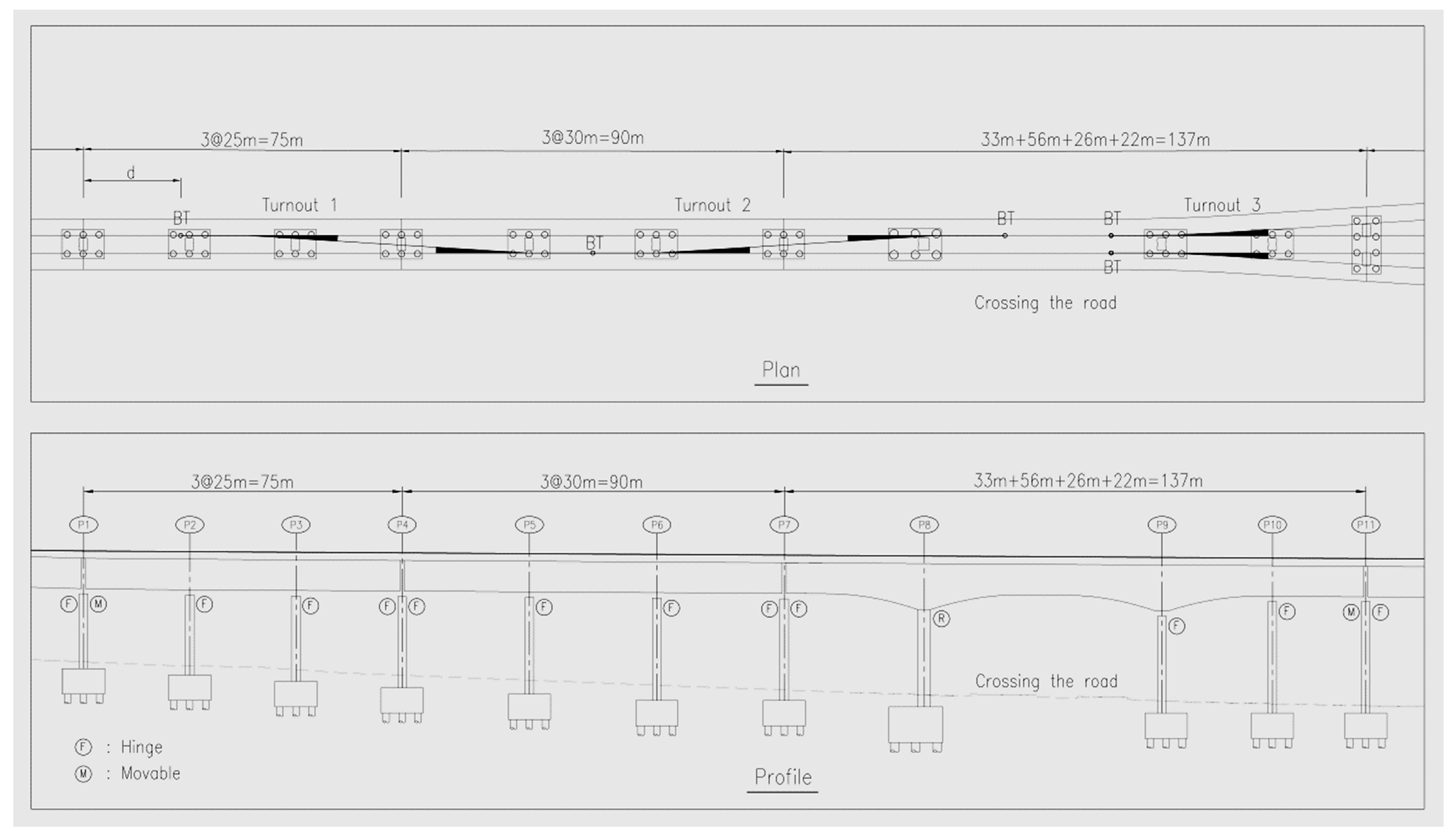
Figure 4.
Temperature, creep, and shrinkage effects on the overall bridge structure.

Figure 5.
Hinged plate A detailed design.
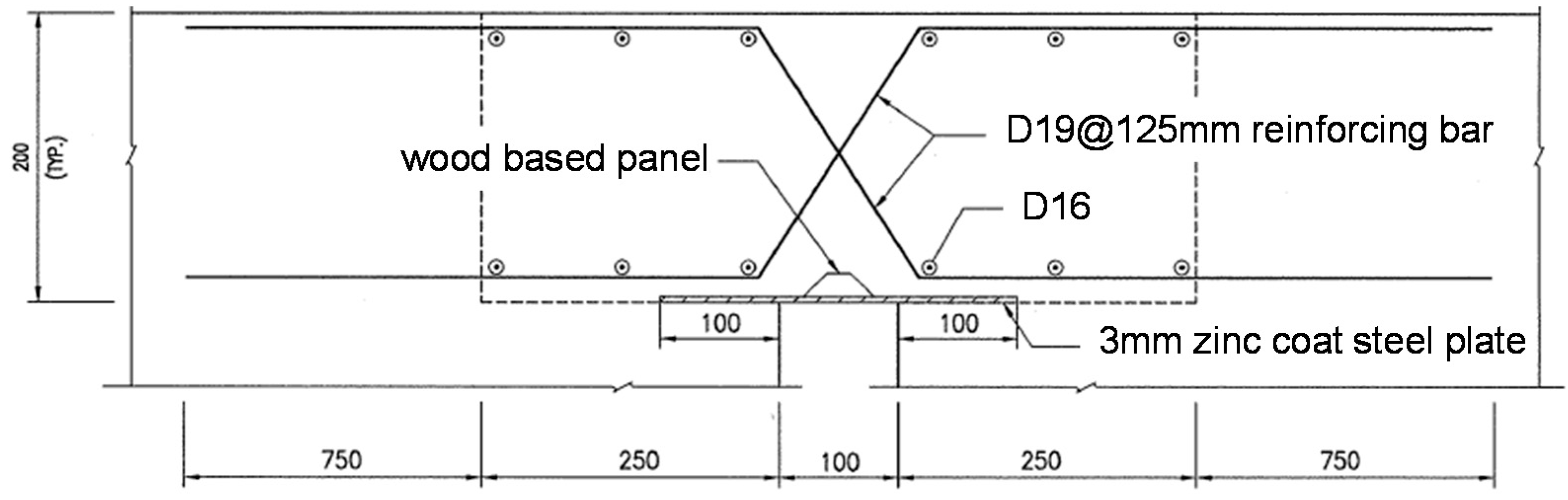
Figure 6.
Cannot set up bridge expansion joint in the turnout zone.
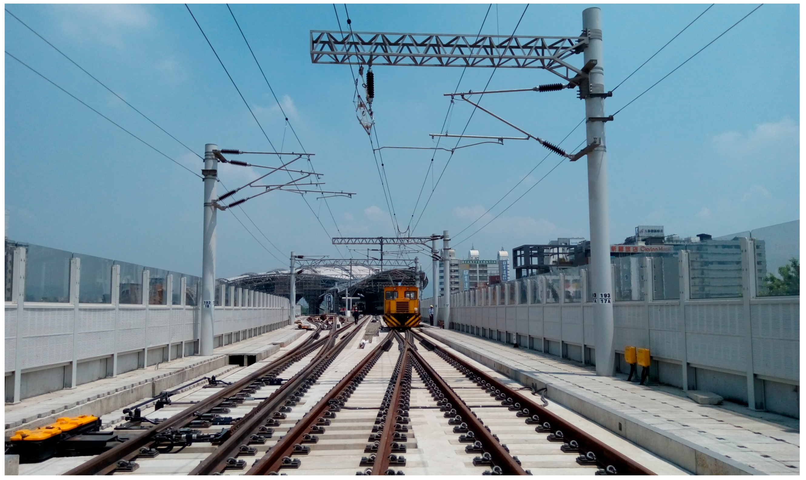
Figure 7.
Considering visual consistency, the adjacent piers adopt prestressed tendons.
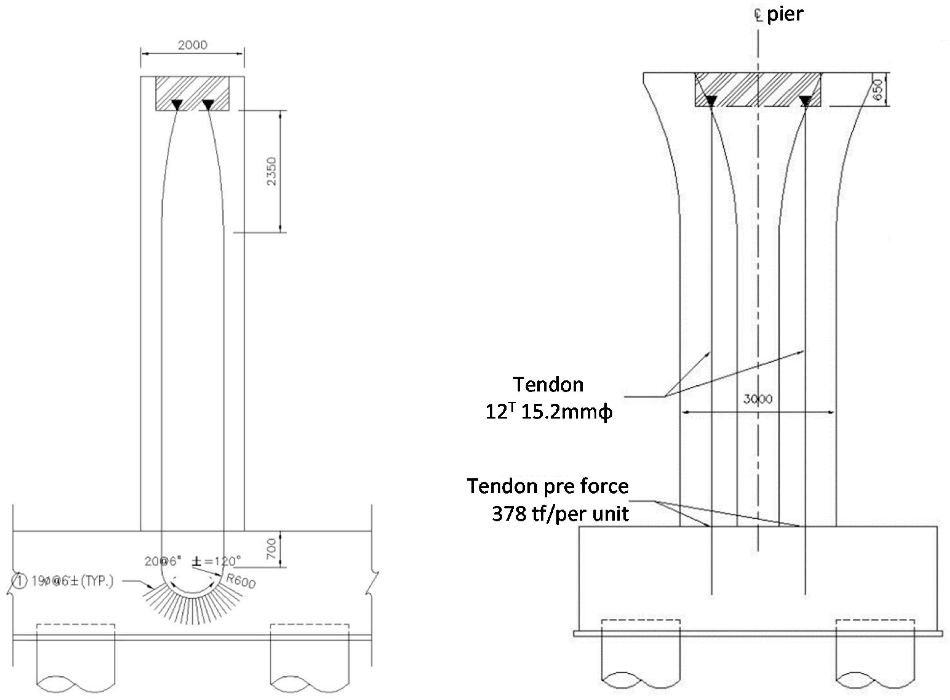
Figure 8.
Visual consistency of the adjacent piers.

Table 1.
Relationship of bridge expansion length L and d values.
| L ≤ 60 m | d ≥ 7 m |
| 60 m < L ≤ 90 m | d ≥ 17 m |
| 90 m < L | d ≥ 27 m |
Table 2.
The axial force analysis of hinged plates by major bridges loading.
| Factors Affecting the Hinge Plate Main Load | 365 Days | 3000 Days | Accumulated |
|---|---|---|---|
| Axial Force (t) | Axial Force (t) | Axial Force (t) | |
| Temperature | 0.00 | 315.78 | 315.78 |
| Creep | 0.00 | 174.75 | 174.75 |
| Shrinkage | 0.00 | 132.13 | 132.13 |
| Summation | 622.66 |
© 2017 by the authors. Licensee MDPI, Basel, Switzerland. This article is an open access article distributed under the terms and conditions of the Creative Commons Attribution (CC BY) license (http://creativecommons.org/licenses/by/4.0/).
Share and Cite
MDPI and ACS Style
Hsu, W.-K.; Shih, N.-H.; Lee, Y.-L. Railway Continuous Prestressed Concrete Bridge Design in Ballastless Track Turnout Zones. Technologies 2017, 5, 11. https://doi.org/10.3390/technologies5020011
AMA Style
Hsu W-K, Shih N-H, Lee Y-L. Railway Continuous Prestressed Concrete Bridge Design in Ballastless Track Turnout Zones. Technologies. 2017; 5(2):11. https://doi.org/10.3390/technologies5020011
Chicago/Turabian StyleHsu, Wen-Kuei, Neng-Hao Shih, and Yu-Lin Lee. 2017. "Railway Continuous Prestressed Concrete Bridge Design in Ballastless Track Turnout Zones" Technologies 5, no. 2: 11. https://doi.org/10.3390/technologies5020011
Note that from the first issue of 2016, this journal uses article numbers instead of page numbers. See further details here.