1. Introduction
Agustin de Betancourt y Molina was a renowned Spanish engineer, who was born in the town of Puerto de la Cruz (Tenerife, Canary Islands) in 1758 and died in the Russian city of San Petersburg in 1824. He made numerous contributions to different areas of Engineering, particularly those related to Civil Engineering. Many publications on the figure of Agustin de Betancourt y Molina span his biography and varied aspects of his life [
1,
2,
3,
4], including his scientific and technical work [
5]. Therefore, given the importance of this work, the Orotava Canary Foundation of the History of Science (Fundación Canaria Orotava de Historia de la Ciencia) has dedicated many years to compiling information on the engineer’s life and works, a digital project entitled “Betancourt” of the Fundación Canaria Orotava de Historia de la Ciencia and offered with free access [
6].
This original and unedited research, which forms part of a doctoral thesis, continues efforts undertaken previously [
7,
8], in which a three-dimensional model with computer-aided design (CAD) techniques of the plunger lock and of the mill for grinding flint was used; both were of the design of Agustin de Betancourt y Molina, notable examples of the historic heritage that makes up part of the legacy of the Spanish engineer. Only one previous graphic-engineering study is available on the historic invention examined here. It was made with the parametric design software Solid Edge ST7 [
9] and therefore a different modeling technique with educational and professional software was used here, i.e., Autodesk Inventor Professional 2016, in order to allow comparisons.
The aim of the present research is to provide a three-dimensional model and geometric documentation of the wind machine for draining marshy ground, using CAD techniques. This will serve in future studies for the static analysis by computer-aided engineering (CAE) techniques with the software Autodesk Inventor Professional.
2. Materials and Methods
The only materials used in the research on the historical invention were those that appear in the website of the digital project “Betancourt” [
10], consisting of two drawings of the machine. Agustin de Betancourt travelled to England during the second year of his stay in Paris (1788) in order to interview James Watt and Matthew Boulton concerning the steam engine recently invented and patented by the two Englishmen. The stay lasted some two weeks and Betancourt had the opportunity to see firsthand the industrial advances being made in the British Isles. The trip, although with some incidents, had the desired result and Betancourt was able, weeks later, to reproduce the double-acting steam engine which he had seen in London. However Betancourt also brought back from London a positive impression of the development of the hydraulic engineering of England. As a result of these reflections, in 1789, he designed a machine for draining marshy ground, which he had taken to Spain to add to the set of machines of the Royal Cabinet of the Buen Retiro (Real Gabinete del Buen Retiro), and for which he later published the specifications [
11].
The above shows that the invention dates to 1789, and, as reflected in the web of the Betancourt digital project [
10], it appears in manuscript 1487, the digitalization of which was provided by the National School of Bridges and Roads of the ParisTech (Paris Institute of Technology). In this report, only two drawings (plans) appear. On the first sheet, appears two dihedral projections of the invention (elevation and lateral view), together with an oblique perspective; and, in the second one, an upper projection (top view) of the rotation system and an oblique perspective of the regulator system for filling the troughs.
As can be seen by the absence of detailed information, both graphic as well as descriptive, it was necessary to formulate certain geometric and dimensional hypotheses for movement so that the ensemble would function properly. Firstly a 3D model was made using the digital restitution method and the computer-aided design (CAD) parametric software, Autodesk Inventor Professional 2016 [
12].
Then the process followed three-dimensional modeling and its geometric documentation is shown in detail, explaining the restrictions applied and the hypotheses formulated so that the design of the historical invention would be consistent.
3. Results and Discussion
The three-dimensional modeling process was quite complex due to the absence of detailed information, both graphic and descriptive, as mentioned above. The two sheets of the invention were not drawn to scale, and, therefore, in the process, the proportions in the drawings were followed in the CAD 3D copy.
For this, different graphic scales were adopted for consistency of design so that the dimensions of the elements of the ensemble were the same as in the drawings, enabling a credible final model. Thus the drawings were not like current technical drafting, in which information is added concerning the manufacturing and assembly processes, as they were not submitted to a standardization process. Rather the designs were conceptual, lacking technical information and consistency in the dimensions of certain elements, which in some cases were never constructed.
Nevertheless it was necessary to formulate certain dimensional and geometric hypotheses, as well as movement restrictions (degrees of freedom) between the different elements of the ensemble, especially in the elements comprising the regulator system for filling the troughs. The joints between parts were both fixed and mobile (permitting turning). In the 3D model, no standardized material was used, since in that period all the metal parts were manufactured by hand. Therefore no calculations were made, either, of the tolerances between the parts assembled.
As opposed to other parametric software used, the process of modeling with Autodesk Inventor Professional allows the components to be individually created in a parametric way (.ipt). These can be modified in 2D with tools of the Autodesk family, such as AutoCAD, and previous designs can be imported for the subsequent assembly of the machine (.iam), based on restrictions of contact and of movement in the individual components, i.e., limiting their degrees of freedom.
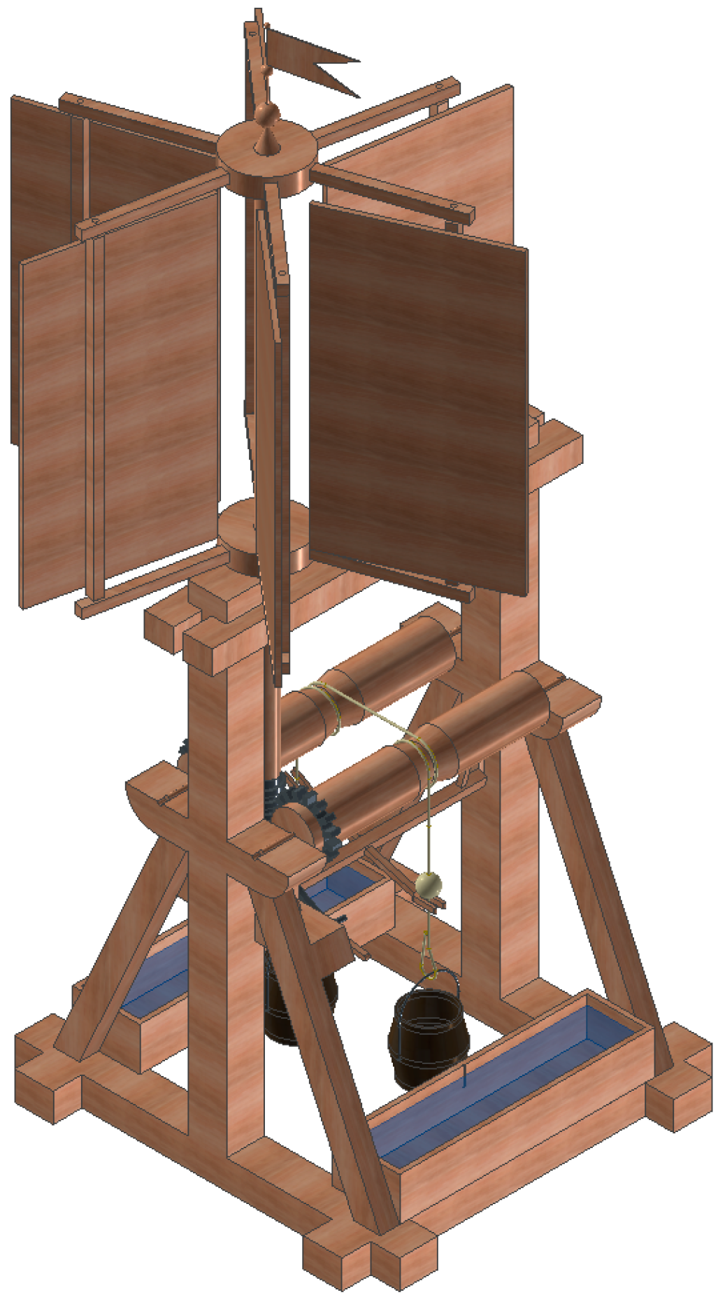
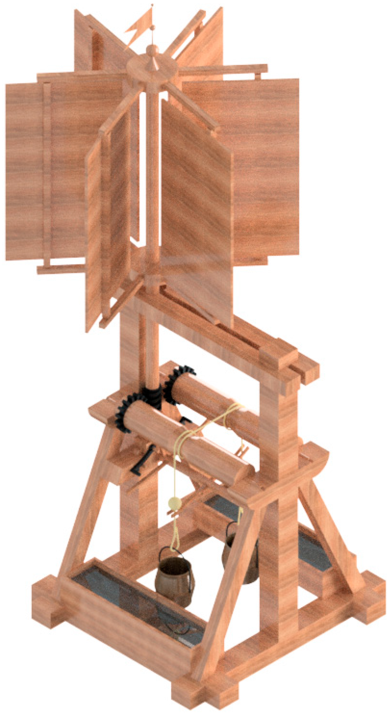
Figure 1 shows an isometric perspective of the 3D model made with CAD techniques of the wind machine for draining marshy ground.
As can be appreciated, the invention consists of a main structure that serves as a support for a vertical-rotation system of vanes that catch the wind and a regulating system for filling the troughs with the drained water.
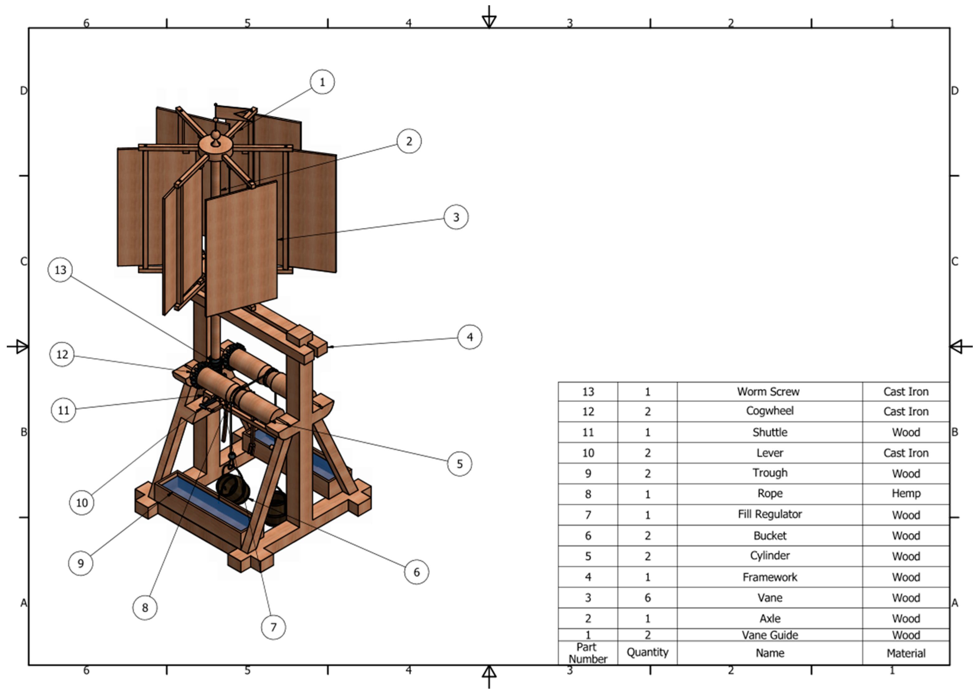
Figure 2 also shows a plan of the ensemble with an indicative list of different elements, while
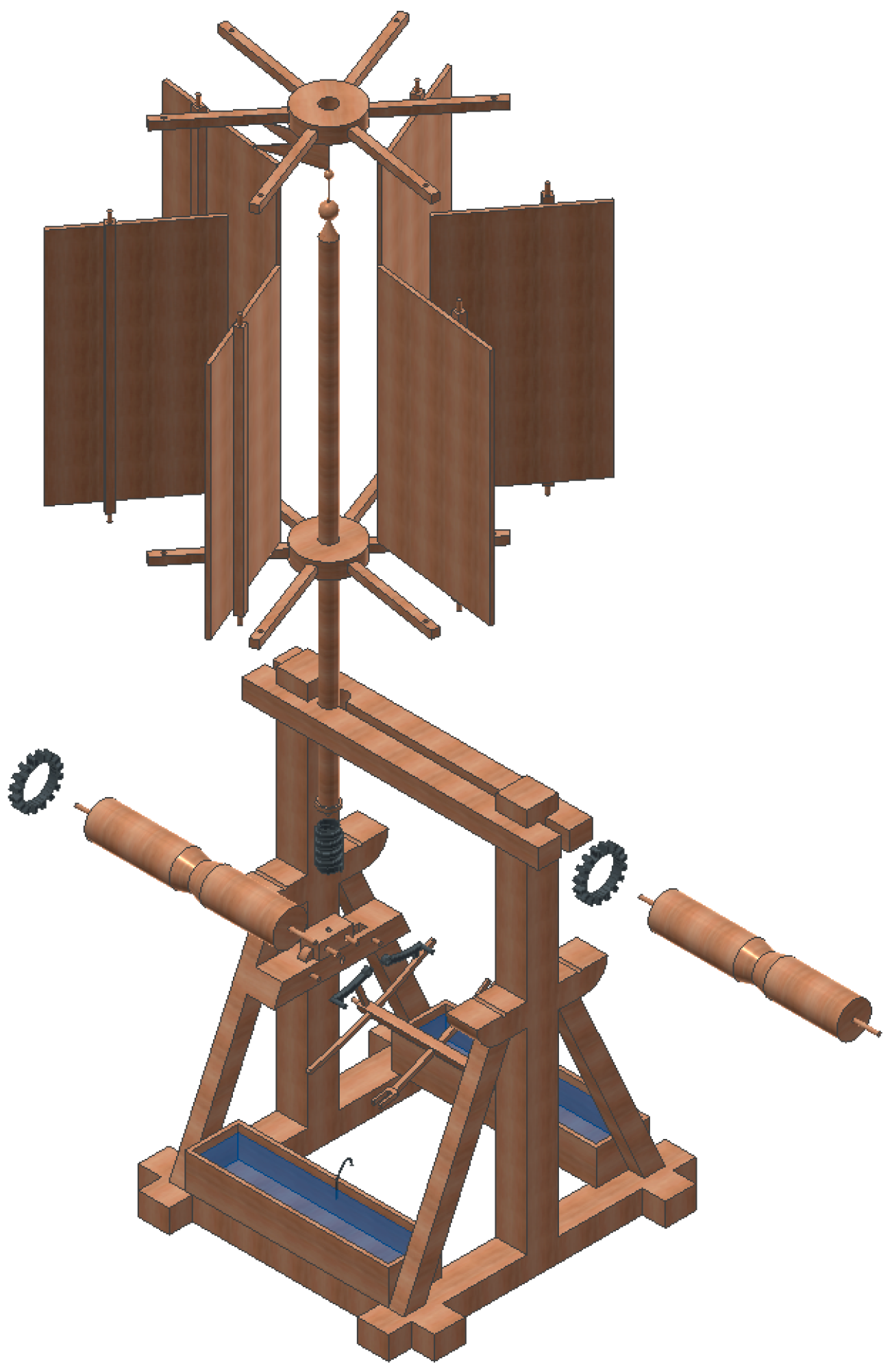
Figure 3 presents an exploded view of the different elements that make up the device, as well as the direction and order of assembly.
3.1. Functioning
The functioning of the machine was divided into two parts; the rotor mechanism and the elevating mechanism. The rotor mechanism was composed of the vanes, the vane guide, and the main axle ending in a worm screw in its lower part. Thus when the wind strikes the vanes (panels of wood), these do not follow a joint reaction with the main axle, as they can turn on an eccentric axis with respect to the main one because of their guides. This allows the vanes to oppose the wind direction only on one side of the mechanism, encouraging the turning, as reflected in
Figure 4.
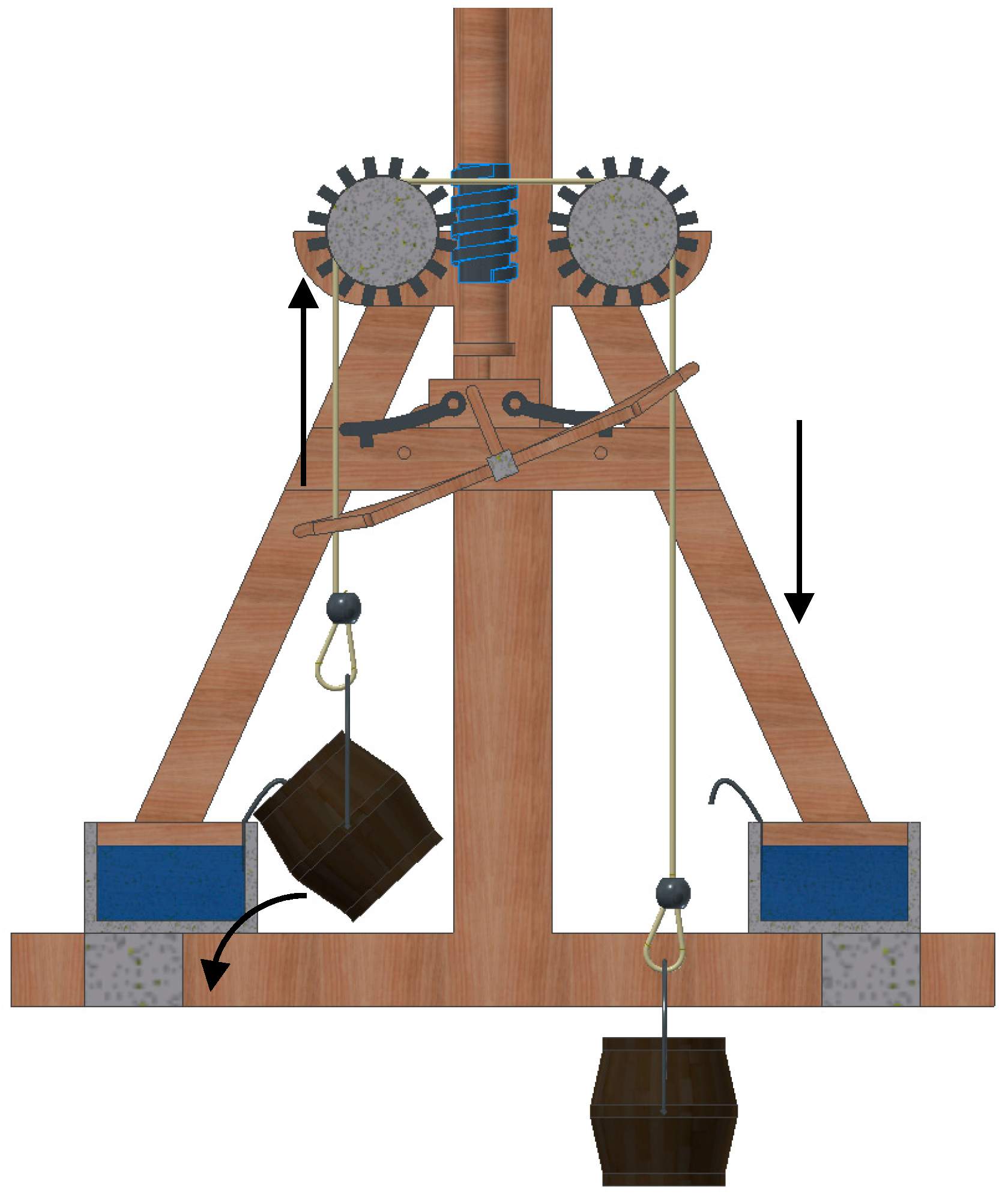
For the elevating mechanism, the turning of the axle and its worm screw activates two cogwheels connected to horizontal cylinders with a channel in the middle. By turning, with a rope looped around each of them in the channel, the cylinders raise one end of the rope and lower the other end, thereby raising and lowering two buckets tied to either end of the rope in order to collect water (
Figure 5).
The full bucket pours its contents into its respective trough and continues rising until the stop (a metal ball fixed to the rope) strikes the fill regulator, causing it to rock upwards. This movement causes it to shift to the other side, moving the lever that displaces the shuttle on which the main axle is supported, thereby shifting this axle. At this, the worm screw separates from the cogwheel raising the rope and shifts towards the other cogwheel. On meshing, this cogwheel begins to turn, causing the inverse movement of the axle, lowering the bucket that was raised, and simultaneously raising the bucket that was lowered and filled with water.
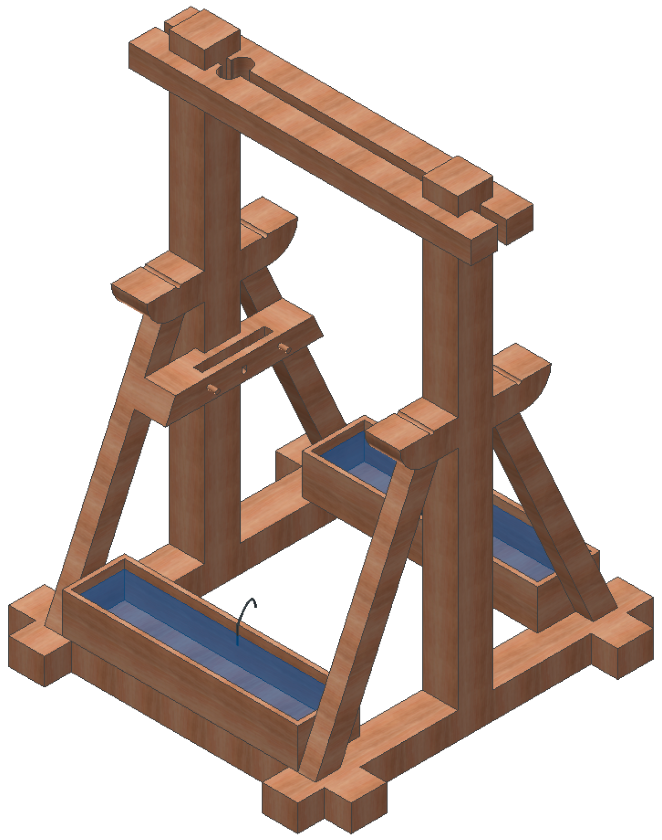
3.2. Modeling of the Framework
The wind machine is supported by a wooden frame which is square in section, as reflected in
Figure 6. This vertical frame rests on a horizontal frame that receives all the stresses of the upper structures and over which there are two posts braced by two diagonal struts, both connected on top by two horizontal cross members slightly separated and drilled on one end to allow insertion of the vertical axle.
Also modeled independently of the framework are two troughs that collect water poured from the buckets; these troughs have a thick hooked metal wire that catches the rim of the full bucket, causing it to tip and pour its water into the trough. However, despite the fact that these two elements rest on the framework, they have no structural function and therefore receive no tension from the rest of the elements.
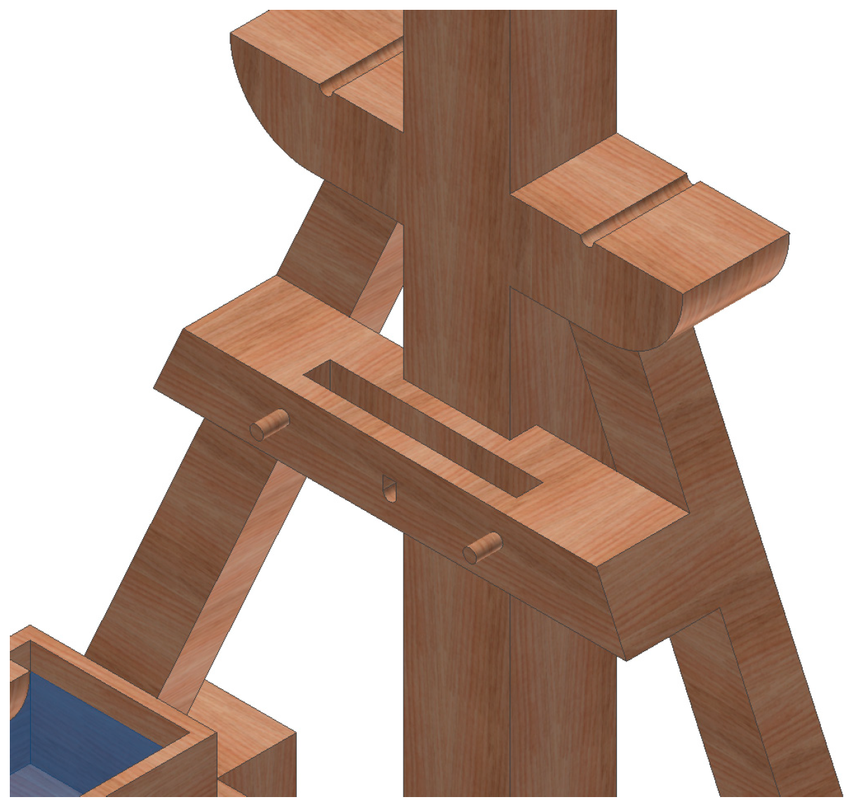
Figure 7 presents the detail of another element of the framework, which is the cross member coupled to the post closest to the vertical axle with a slot cut in its upper part. This member is the guide for the wooden shuttle, which will be mentioned below and which enables the horizontal movement of the vertical axle. Finally, in the part where the struts come together at an angle with the posts, appear two wooden supports for the two cylinders that end in the two cogwheels that convert the horizontal movement into vertical movement. These elements were modeled together with the frame that supports the entire structure, since they do receive stresses from different elements, including those from the upper structure as well as those generated in the process of loading the water in the buckets.
3.3. Modeling of the Rotor Mechanism
The rotor mechanism is the element that drives the entire wind machine, and its design reflects the originality and pragmatism of the designer. Wind machines with a vertical axis are uncommon in Europe, although they were certainly known early on. The vertical-rotation mechanism designed by Betancourt results from a vertical axle connected towards the bottom to a simple worm gear.
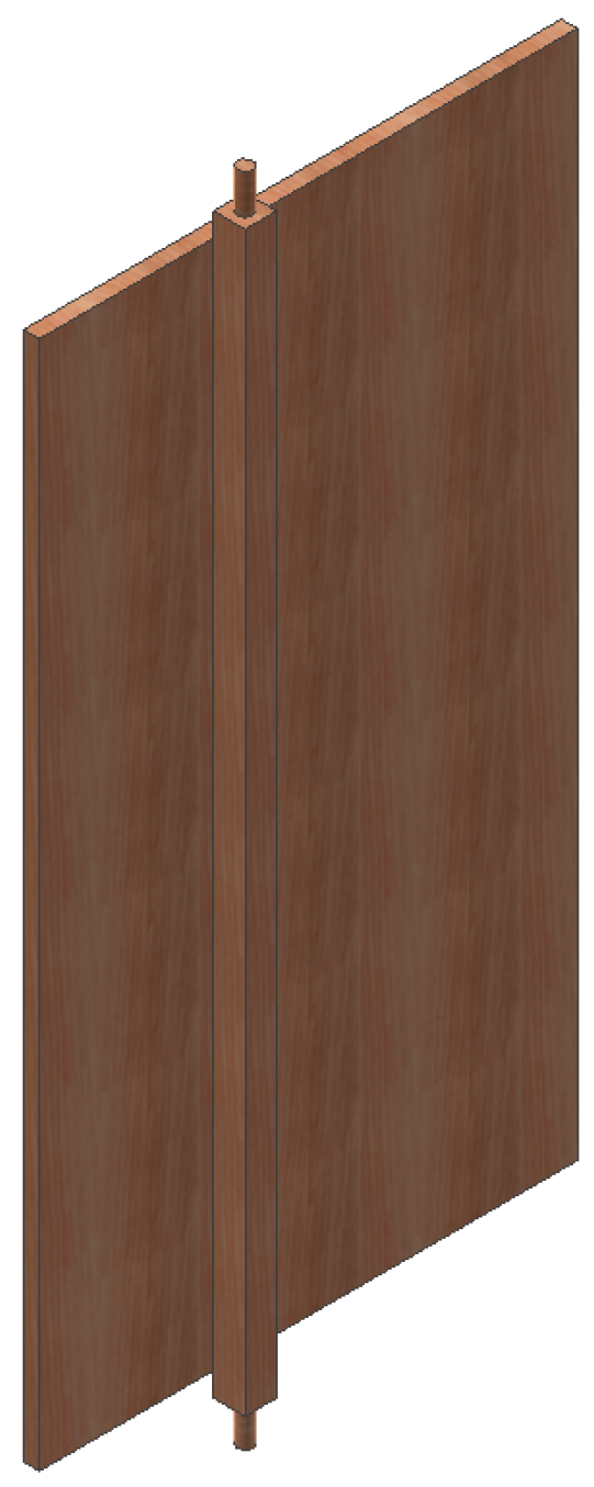
The axle is coupled to two guides; an upper one and a lower one designed to house six rectangular vanes (
Figure 8). The vanes are connected to the guides by dowels fitted through the holes in the guides (
Figure 9), these elements being modeled independently of one another. The vertical axle moves with the guides, as these are inserted into a square hole and fixed. Meanwhile the vanes are free to revolve over the dowels regardless of the position of the vertical axis.
As can be seen, the upper part of the machine has a number of wooden decorative details, including a weathervane to indicate wind direction. The worm screw fixed to the axle is made of cast iron; this element meshes with the cogwheel of the cast-iron fixed to the wooden cylinders so as to minimize wear.
For the choice of the wood type for the different parts of the vertical-rotation mechanism, it was taken into account that it should be flexible, as the main deformations of this part of the structure are due to buckling. However, with respect to the model presented by Betancourt, there is a minor difference. That is, while the engineer proposed a rod as a stop to limit the rotation of the vane, the recreated model presents small stops of barely a few centimeters long in the same guide. These present less opposition to the wind and therefore provide a better use of the energy, fulfilling the same function as the rod hanging from the upper to the lower guide. The function of these stops is to prevent the vane from completely rotating; without them the vane would not resist the wind in any position and therefore there would be no rotation of the vertical axle (
Figure 4).
3.4. Modeling of the System Regulating the Bucket Filling
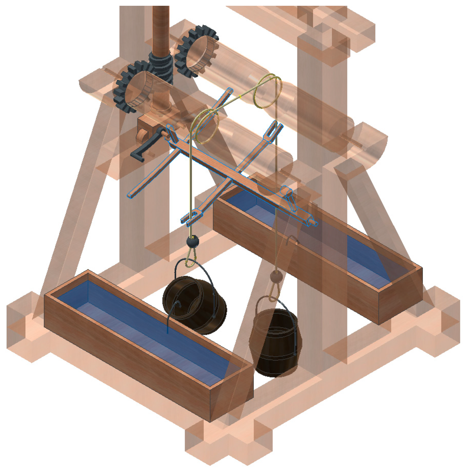
The system for filling the buckets also indicates the originality of the engineer. A general view of the system (
Figure 10) shows its main components.
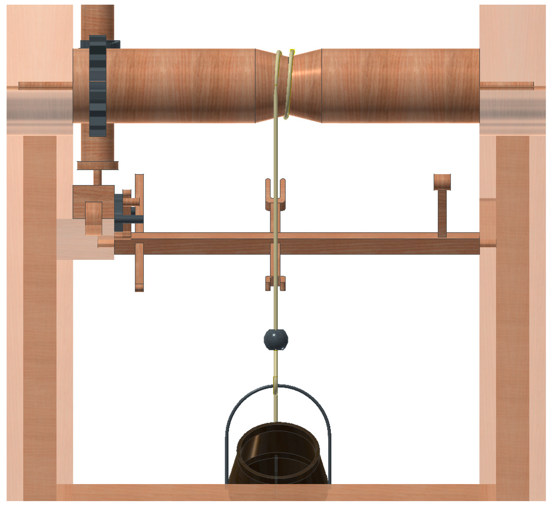
First two wooden cylinders serve to coil and uncoil the rope that raises and lowers the buckets.
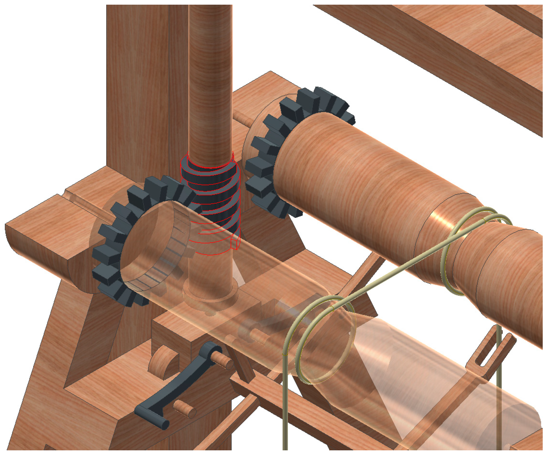
Figure 11 highlights the perpendicular position of the cylinders with respect to the vertical axle of the rotation system, transmitting this movement from the worm screw to the cogwheel fitted to each cylinder (
Figure 12).
For the modeling of the metal cogwheel of the cylinders, the thread pitch of the worm screw was taken into account. The data provided by the original drawings did not give detailed dimensions of the worm screw but it was modeled to be compatible with the characteristics and diameter of the cylinders.
For an easy gear ration between the vertical axle and the horizontal cylinders, a relation was established of 1:16, thereby allowing the vertical movement of raising the buckets to be less abrupt and cause less wear on the rotational elements. The rope looped around the two cylinders is not only a lifting element but also transmits the movement of one bucket to the other (
Figure 12). So that this transmission functions correctly, the rope must be completely encircle each cylinder and the buckets must have sufficient weight to maintain the rope taut. When these circumstances are fulfilled, the clockwise turning of one of the cylinders causes the other also to turn.
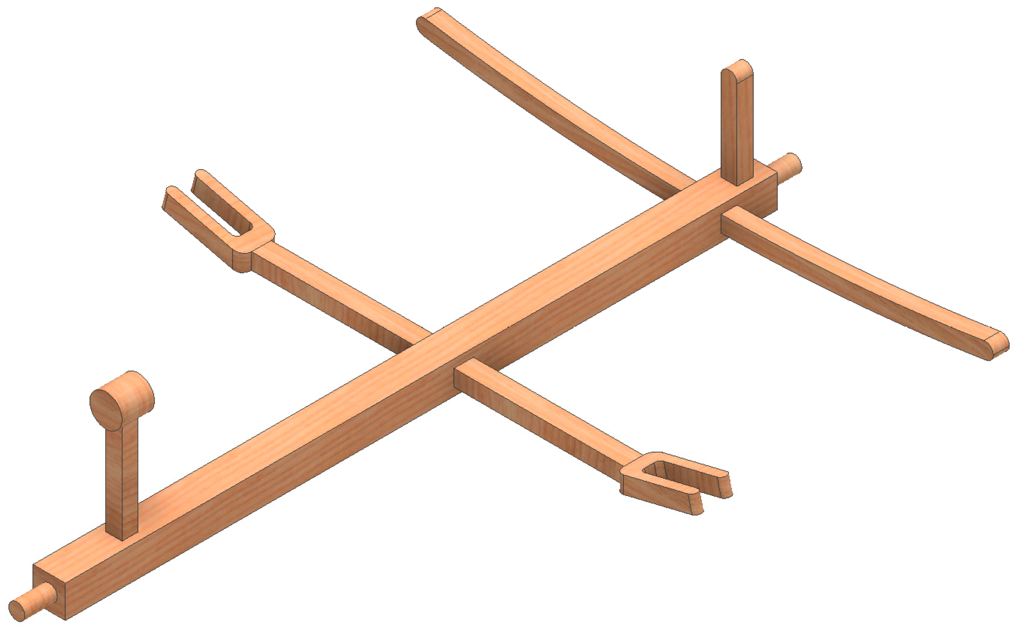
Figure 10 shows an unusual, ingenious part that has a crucial function for the operation of the mechanism, i.e., the regulating axle (
Figure 13). This axle has a square section and is supported horizontally by a dowel in each end for rotation and has several elements with functions that act in concert. First, on the left end, an inverted pendulum facilitates the rocking movement in one direction or the other. Second two forked clips extend from the central area, on the right end are two curved bars, and a small hammer is placed in the axle. In addition, the ensemble of the regulating axle was modeled in a single piece of wood although it would have to be manufactured in several pieces or some of the elements would need to be replaced.
The function of this element is to stop the ascent of one the buckets and to begin the ascent of the other one. The rope passes through the forked clips and when the stop (metal ball) strikes the clip, the axle begins to rock towards a position of equilibrium. Once this position is reached, the inertia of the inverted pendulum causes the axle to rotate in the opposite direction. The curved bars under the hammer raise the lever that has caught the stop, freeing the movement of the shuttle. Afterwards the hammer strikes the contrary lever, moving the shuttle from one end to the other until it becomes caught in the opposite stop. Over the shuttle, stands the end of the vertical axle and therefore the worm screw, which, on moving to the other end, meshes with the other cogwheel, thereby turning the cylinders and beginning the ascent of the bucket full of water.
Although the shuttle where the levers are situated is made of wood, the levers should be made of metal (
Figure 12) due to the wear of constant striking and the necessity of maintaining their freedom to rotate. In addition, although this component supports the weight of the vertical axle, it is the rotational movement of the vertical axle that facilitates the movement of the shuttle in one direction or another.
3.5. Final Assembly
Figure 14 shows the final assembly. This is a more photorealistic image achieved using the rendering provided by Autodesk Inventor Studio, which incorporates Autodesk Inventor Professional.
After the modeling of the all the parts of the machine, only assembly remained. First the structure of the frame was fixed to serve as the support for all the mechanisms of the device, the troughs and wire hooks were added over the frame. The troughs had restricted movements in the three planes on which they are snugly fit to the frame (
Figure 6).
Next, to assemble the vertical-rotation system, the shuttle was placed on the horizontal member of the intersection of the post and the diagonal struts. The shuttle was restricted to move in two directions, given that the third direction is free in order to move it longitudinally over the horizontal surface. On top of the shuttle, stands the axle of vertical-rotation with the worm screw in its lower end, both presenting the same restriction with respect to the hole in the shuttle where the axle is supported. The upper and lower guides are inserted into the top part of the axle and are solidly joined to the axis. The outer ends of the guides have holes that align with the dowels of the rectangular panels (
Figure 9). To arrange them in this way and permit rotation, two restrictions of coincidence and plane are established. Finally the contact between the panel and the guide is activated, so that the stop of the guide restricts the complete revolution of the panel over its guides.
In addition, for the assembly of the filling mechanism, the process begins by aligning the regulator axle. The frame has holes with respect to those that establish a restriction of coincidence per hole. In addition to this restriction of coincidence, one of the planes of movement must be restricted so that it can turn without moving from its position (
Figure 10).
The next step consists of fixing the position of the cylinders in their guides. For this, the same restriction is used as in the foregoing case, but, furthermore, the contacts that it may have with the worm screw must be activated. This is determinant for the correct transmission of the movement (
Figure 12). Next the levers are inserted into the shuttle with one restriction of coincidence with the dowels of the shuttle and another with respect to the plane of the shuttle that the lever supports, permitting the lever to swivel freely on its dowel. After the lever is positioned, the contacts between it and the regulating axle are activated, since, if this is not done, the hammer will not be able to push the shuttle.
The last phase of the assembly, which is quite difficult, is the placement of the looped rope over the cylinders and the hanging of the buckets. Each bucket has a swivel handle that makes it able to tip over, and the ends of the handle are adjusted to permit their turning in the holes bored in the bucket for this purpose. The contacts of the bucket must also be activated in order to be caught by the hooked wire so that the water spills. On the other hand, the handle is solidly fixed to the rope, which has only one degree of freedom of movement (up and down), and finally, the metal ball should have its contacts activated so that on striking the forked clip of the regulating axle, it rotates towards the opposite side (
Figure 10).
4. Conclusions
The present study shows the process followed in building a three-dimensional model and compiling the geometric documentation of the wind machine for draining marshy ground designed by Agustin de Betancourt y Molina. For this, the parametric software Autodesk Inventor Professional was used.
In this three-dimensional modeling process, it was necessary to formulate hypotheses concerning the dimensions and functioning as well restrictions of movement (degrees of freedom) between different elements, as this information did not appear in the drawings made by the engineer. The aim was to design the elements that reflected the proportions of the original drawings and that provided consistent functioning of all the parts. In this way, a virtual recreation of its assembly and functioning was achieved, to be used for educational purposes. In addition, in the near future, a prototype will be printed of this invention in a high-quality 3D printer, ensuring the functioning of the machine, so it is necessary for the 3D model to be accurate and permit an STL format (STereo Lithography) for optimal results of the printing.
In addition, the assembly of the mechanism is not excessively complex, and the elements comprising it have simple shapes. However the only dimensional hypothesis that might need some correction would be the gear ratio between the worm screw and the cogwheel on the cylinders, since it is possible that the speed of the buckets’ emptying might increase at gear ratios of lower than 1:8 or 1:4. Therefore, in future research, a static analysis will be made of the machine using CAE techniques, observing the von Mises stresses, the displacements, and the coefficient of safety of the invention, as well as using classical engineering for verification.


