Article

Experimental Tests on Steel Plate-to-Plate Splices Bonded by C-FRPS Laminas with and without Wrapping

by
Mario D’Aniello
*,
Francesco Portioli
and
Raffaele Landolfo
Department of Structures for Engineering and Architecture, University of Naples “Federico II”, Naples 80134, Italy
*
Author to whom correspondence should be addressed.
Technologies 2016, 4(1), 5; https://doi.org/10.3390/technologies4010005
Submission received: 5 December 2015 / Revised: 30 January 2016 / Accepted: 2 February 2016 / Published: 15 February 2016
(This article belongs to the Special Issue Bolted and Bonded Joints in Fibre Reinforced Polymer Structures)

Abstract

:
The results of an experimental investigation carried out on steel splices bonded by (Carbon-Fiber–Reinforced Polymers) C-FRPs are presented in this paper. The main aim of the study is to examine the influence of different parameters on the type of failure and on the ductility of splices. Different configurations of the specimens were considered, including butt and lapped joints using different arrangements for end anchorage of the bonded C-FRP laminas, such as (i) external bonding; and (ii) anchored jacketing with C-FRP sheets transversally wrapped to the longitudinal axis of the joints. The results in terms of failure modes and response curves are described and discussed, highlighting the potentiality of these types of bonded connections for metal structures. In particular, experimental results showed that (i) the failure modes exhibited by both butt and lapped wrapped splices were substantially similar; (ii) the wrapped anchoring is beneficial in order to achieve large deformations prior to failure, thus allowing a satisfactory ductility, even though a more timely installation process is necessary.

1. Introduction

Historic metallic structures represent a significant portion of the architectural and cultural heritage in most European countries. The majority of these constructions is still in service and is exposed to service actions that are larger than was expected [1]. The reliability and the structural performance of this category of constructions are also affected by age-related and environmentally-induced deterioration and the low mechanical performance of the constituting materials. Outcomes from the European research project “Sustainable Bridges” [2] showed that aged steels do not usually fulfill the requirements of EN 10025 [3] for standardized materials. Thus, there is an urgent need to verify the compliance of historic steel structures with current standards and to assess their residual lifetime.
The traditional strengthening method for steel structures is to cut and replace steel plates or to attach additional plates to existing members. However, these techniques do not preserve the structure from deterioration, since steel plates are prone to corrosion and fatigue [4].
The use of composite materials is a very promising and increasingly economic method for strengthening steel structures [4,5,6,7,8]. In particular, the application of externally bonded Carbon-Fiber–Reinforced Polymer (C-FRP) plates [4,5,6,9]. This technique allows the increase of both the strength and buckling capacity of steel members and also the fatigue-life extension [5,6,10] and crack-patching [11,12].
The effectiveness and reliability of this strengthening/repairing method is mainly guaranteed by the anchorage of the fibers, which typically fails before the plates achieve their tensile capacity. Therefore, the debonding of FRP from the steel elements must first be addressed in order to obtain a fully composite action. The first critical aspect is to clarify the bond-slip characteristics of FRP-plated steel members, which are mainly influenced by the bonding length and the adhesive layer behavior.
In particular, the adhesive is the weakest link in C-FRP-to-steel bonded joints [4,11,12]. To analyze the adhesive characteristics and to investigate the type of failure of CFRP-bonded joints, many authors have performed a series of experimental tests.
Zhao et al. [4] discussed the main research activity on FRP-strengthened steel structures, and illustrated the progress on the bond between the steel and FRP, the strengthening of steel hollow section members, and the fatigue crack propagation in the FRP-steel system.
Xia et al. [13] studied the behavior of the epoxy layer by performing some pull-out tests in which the FRP-to-steel interface is subjected to direct shear. A bond-slip model was also performed, and the main adhesive characteristics were discussed.
Yong-xin et al. [14] performed some bonding tests on CFRP-strengthened steel elements varying the type of adhesive, and then they studied the durability of the chosen type of adhesive. An aging model of the bond behavior of C-FRP-to-steel in a man-made seawater environment has been also proposed.
Nowadays, existing standard [15,16] and purely empirical procedures [4,5,6,7,8,9,10,11,12,13,14,17] mislead the derivation of the bond-slip characteristics because of the difficulty in measuring the strain distributions and capacities in the small region where debonding occurs.
The present paper describes the results of an experimental study aimed at investigating the influence of different bonding lengths on both the type of failure mode of the joint and the ductility of the failure process.
This work is part of an extensive experimental activity devoted to determining the main characteristics of CFRP-strengthened steel elements, in order to design and test C-FRP strengthening on riveted connections, which represent the main typology of joint for historic metal structures [1].
The paper is organized as follows: in Section 2 the experimental program is illustrated, in Section 3 the main experimental results are described, and in Section 4 the main conclusions are drafted.

2. Experimental Program

2.1. Investigated Parameters and Experimental Program

A total of 30 bonding tests were prepared, as summarized in the program matrix reported in Table 1. The investigated parameters are explained as follows:
(1)
Bonding length: This parameter may noticeably affect the failure load [18]. Therefore, different strip lengths were examined in order to verify the effectiveness of the strengthening in accordance with Italian code provisions [15], in particular 150 mm, 200 mm (value recommended by the Italian code [15]) and 250 mm.
(2)
Wrapping sheet: The effects of the anchored jacketing by wrapping composite sheets were analysed considering, alternatively, 100 mm and 150 mm widths of wrapping sheets.
(3)
Load eccentricity: Both butt and lapped plates were considered in order to analyse the effects of secondary bending moments induced by load eccentricity on adhesive deformation and strength.
The geometries of the investigated connections are shown in Table 2. Specimens were labeled as C-B-W, where:
  • C is the splice configuration (e.g., B: Butt; U: Unsymmetrical lapped);
  • B is the bonding length (e.g., 150, 200, 250 mm);
  • W is the wrapping depth (e.g., 100, 150 mm);
Three nominally identical samples were built up for every type of specimen.
Table 1. Experimental program matrix.
Specimen TagButtUnsymmetricalB (mm)W (mm)Test No.
Unwrapped
B150 150 3 (a, b, c)
B200 200 3 (a, b, c)
B250 250 3 (a, b, c)
U-B150 150 3 (a, b, c)
U-B200 200 3 (a, b, c)
U-B250 250 3 (a, b, c)
Wrapped
B150W100 1501003 (a, b, c)
B150W150 1501503 (a, b, c)
U-B150W100 1501003 (a, b, c)
U-B150W150 1501503 (a, b, c)
Total test 30
Note: B: bonding length; W: wrapping depth.
Table 2. Geometry of specimens.
ButtLapped
Unwrapped Technologies 04 00005 i001 Technologies 04 00005 i002
Wrapped Technologies 04 00005 i003 Technologies 04 00005 i004

2.2. Experimental Set-Up and Monitored Parameters

The experimental setup is shown in Figure 1a. In particular, a universal electro-mechanical Zwick/Roell testing machine (see Figure 1b) was used to carry out tests. The specimens were loaded in tension under displacement control until failure, i.e., after the load decreased.
The maximum load reached and the types of failure modes were observed for each test. The relative in-plane displacement of tested specimens was measured by means of a couple of LVDTs (Linear Variable Differential Transformer), which were characterized by a displacement range of ±150 mm and positioned on both ends of the C-FRP lamina (Figure 1c,d). The displacement rate was fixed at 0.1 mm/s and an acquisition frequency of 10 Hz was assumed [1].
Figure 1. Test setup (a); the testing machine (b); the layout of LVDTs (c,d).
Technologies 04 00005 g001
The parameters that have been monitored and post-processed for the tests are illustrated in Figure 2a for C-FRP-bonded splice joints without wrapping and in Figure 2b for the wrapped specimens, where the symbols are explained as follows:
-
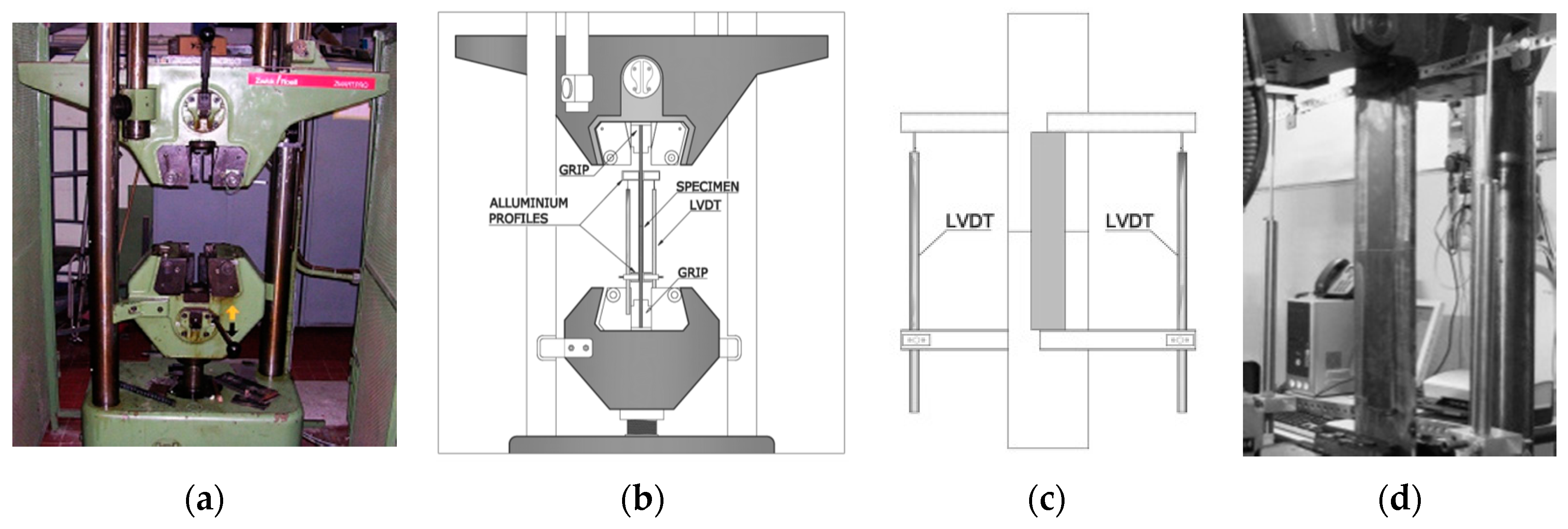
δ = (δLVDT1 + δLVDT2)/2: Average displacement (being δLVDTi the displacement recorded by the ith LVDT);
-
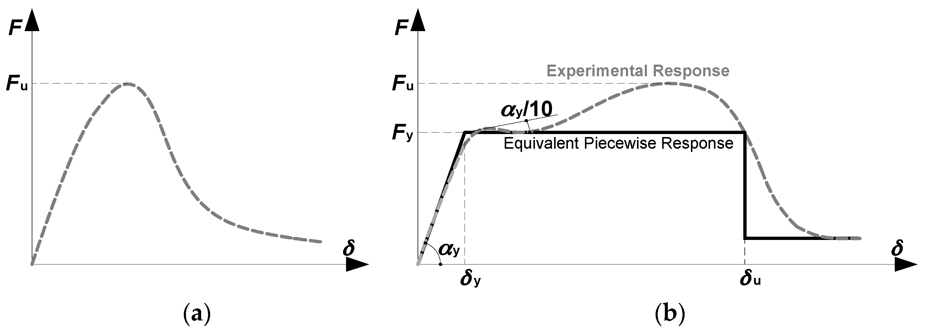
Fy: Conventional elastic strength determined according to European recommendations for testing steel elements developed by European Convention for Constructional Steelwork (ECCS), i.e., ECCS-45 [19]. In particular, this approach requires the following steps: (1) evaluating the tangent line at the origin of the force-displacement, it gives a slope equal to αy (see Figure 2b); (2) locating a tangent line tilt of αy/10 on the experimental response (see Figure 2b); (3) the intersection of the two tangents defines the level of Fy;
-
Fu: Ultimate strength, which is the maximum recorded average load;
-
δy: Slip corresponding to Fy;
-
δu: Displacement corresponding to a load equal to Fy on the post-peak branch of the response curve
-
μ = δu/δy: Displacement capacity.
Figure 2. Monitored mechanical parameters [20]: without wrapping (a); with wrapping (b).
Technologies 04 00005 g002
In particular, it should be noted that the displacement δy corresponding to Fy and the displacement capacity μ were monitored to provide an estimate of the equivalent ductility of the splices. These parameters were solely extracted for specimens with wrapping because these splices were able to provide a large displacement capacity. Conversely, as shown hereinafter, the specimens without wrapping showed a very brittle behavior.

3. Experimental Results

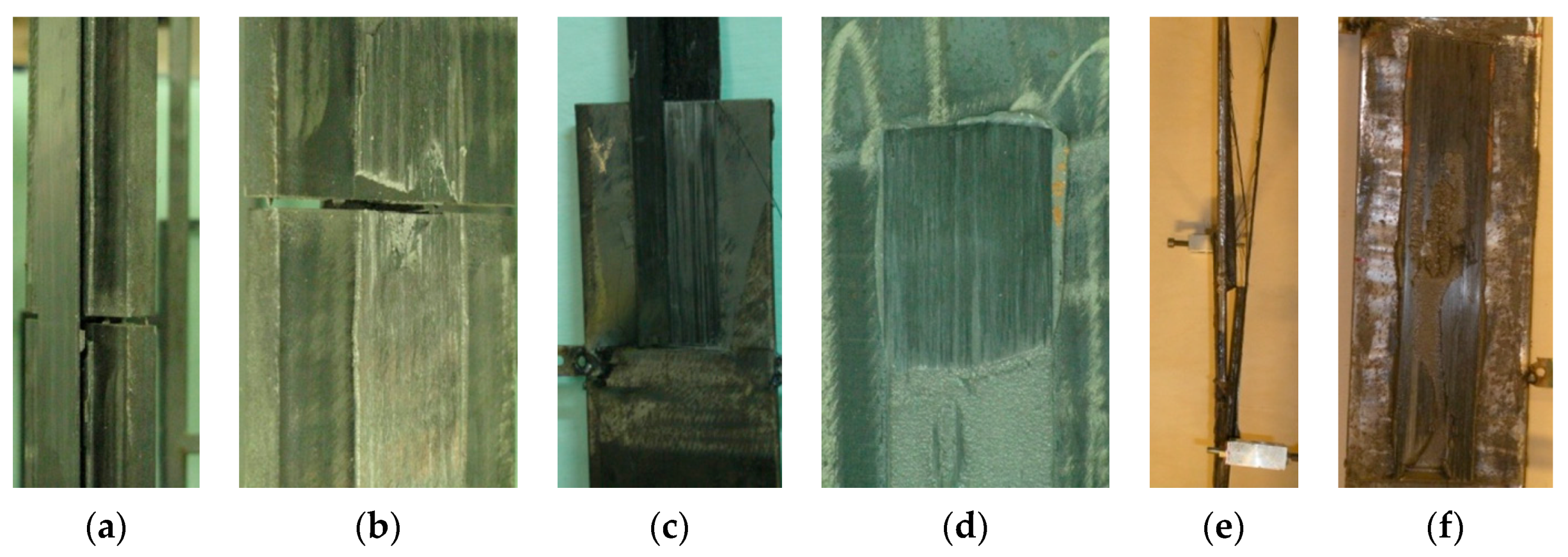
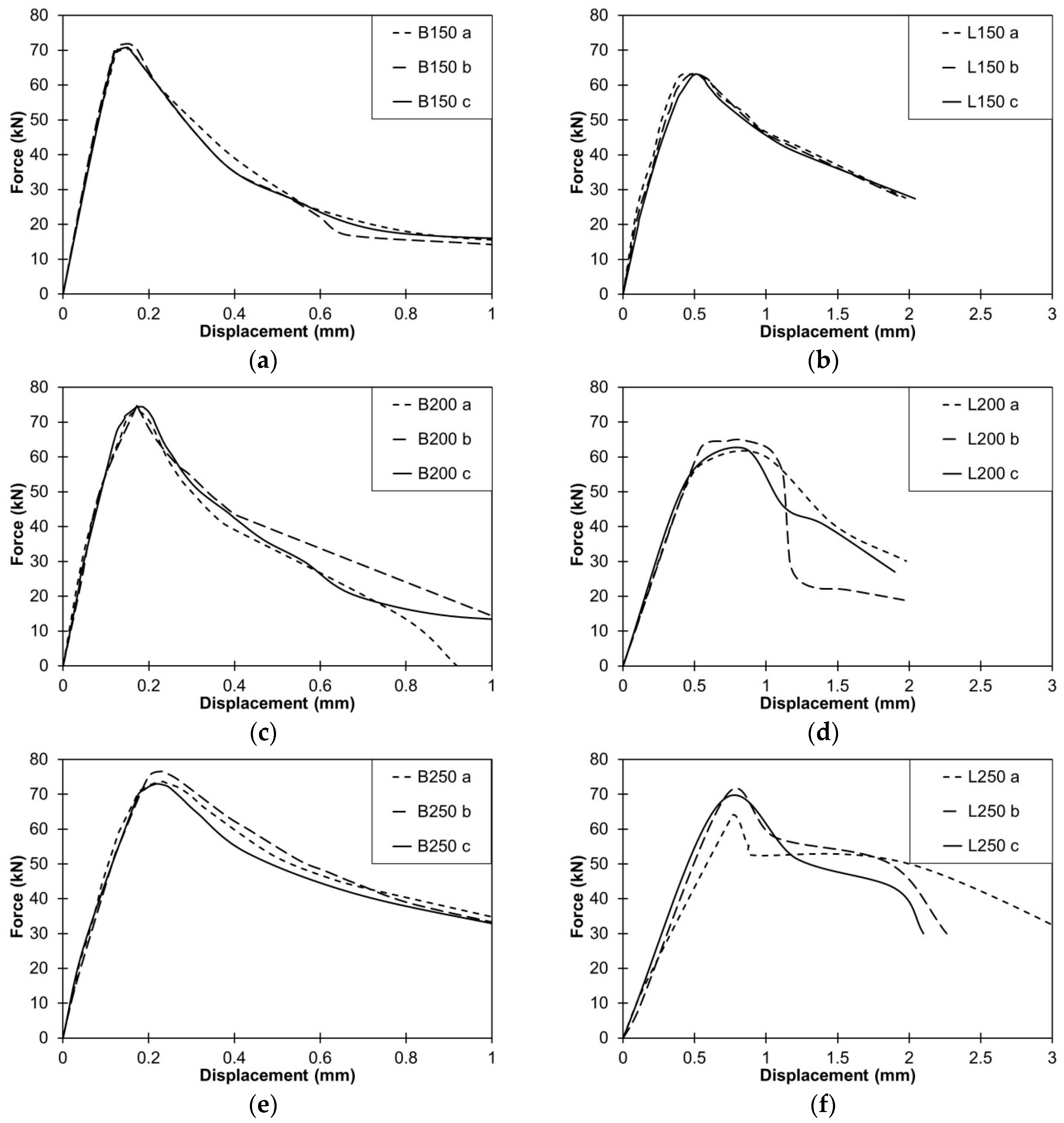
3.1. Unwrapped Specimens

Test results in terms of both failure modes and experimental response curves are summarized in Figure 3, Figure 4 and Figure 5. Three basic types of failure modes were observed: (a) adhesive layer failure (Figure 3a,b); (b) C-FRP and adhesive interface failure (Figure 3c,d); (c) C-FRP delamination, namely the separation of some carbon fibers from the resin matrix (Figure 3e,f). In some cases a mixed mechanism made of adhesive layer failure and C-FRP delamination occurred. A similar performance (namely failure mode and force-displacement response) was observed for both butt and lapped specimens without wrapping.
Figure 3. Failure modes of C-FRP bonded splice joints without wrapping [20].
Technologies 04 00005 g003
Figure 4. Experimental response curves of C-FRP bonded splice joints without wrapping [20].
Technologies 04 00005 g004
Figure 5. Failure modes of C-FRP bonded splice joints with wrapping [20].
Technologies 04 00005 g005
Tests showed that the debonding started at the gap area between the steel plates. With the strength of steel plates larger than the strength of the composite strips, we also consider the type of adhesive layer and the stiffness of composite laminas. In the tests presented in this paper, the steel plates behave elastically and the axial stiffness of the laminas is lesser than those of the steel plates. These aspects might have induced the brittle response of splices, which can be observed in the force-displacement response curves depicted in Figure 4. From these plots it can be noted that all butt splices showed an initial stiffness larger than the rigidity exhibited by lapped configurations. This result is ascribable to the different lengths of the two sets of specimens, with the lapped splices being longer than the butt specimens in order to allow gripping the plates in the test machine. In addition, the presence of secondary bending effects was another source of deformability.
Table 3 summarizes the geometrical and mechanical parameters monitored during each test. In particular, Table 4 reports the measured thickness of the adhesive layer, considering that this parameter could have considerable effect on the bond behavior. In the present study it was found that in all cases with a thicker adhesive layer, the failure mode was mainly characterized by C-FRP delamination, thus being consistent with the results in the literature [21,22].
Table 3. Specimen details and test results for C-FRP-bonded splice joints without wrapping [20].
Specimenta * (mm)Fu (kN)Failure Mechanism
MeanSDCVTest ValueMeanSDCV
B150 a0.490.090.1870.3771.000.770.01Delamination
B150 b0.560.080.1471.86Delamination
B150 c0.540.110.2170.76Delamination
B200 a0.410.080.1973.2273.780.670.01C-FRP to adhesive interface + Delamination
B200 b0.400.090.2274.53Adhesive/Delamination
B200 c0.410.100.2473.60Adhesive/Delamination
B250 a0.380.070.1876.5974.711.800.02Adhesive/Delamination
B250 b0.390.090.2373.01Adhesive/Delamination
B250 c0.410.090.2274.53C-FRP to adhesive interface
L150 a0.380.090.2463.0363.080.090.00Adhesive/Delamination
L150 b0.360.080.2263.18Adhesive/Delamination
L150 c0.390.110.2863.01Adhesive/Delamination
L200 a0.400.080.2060.6163.152.260.04C-FRP to adhesive interface
L200 b0.380.090.2463.89C-FRP to adhesive interface
L200 c0.370.100.2764.94C-FRP to adhesive interface + Adhesive/Delamination
L250 a0.410.070.1763.8967.183.050.05C-FRP to adhesive interface
L250 b0.390.090.2369.91Adhesive/Delamination
L250 c0.390.090.2367.73Adhesive/Delamination
* ta is the thickness of the adhesive layer measured at 10 sections equally spaced along the axis of the splice. SD = Standard Deviation, CV = Coefficient of Variation.
Table 4. Specimen details and test results for C-FRP-bonded splice joints with wrapping [20].
Specimenta * (mm)Fy (kN)Fu (kN)μ = δuy F y , w r a p p e d F u , s i m p l e   b o n d e d F u , w r a p p e d F u , s i m p l e   b o n d e d
MeanSDCVTest ValueMeanSDCVTest ValueMeanSDCVTest ValueMeanSDCV(-)(-)
B150
W100 a
0.380.090.2376.6077.321.150.0184.4981.622.620.036.123.832.420.631.091.15
B150
W100 b
0.350.100.2878.3679.361.29
B150
W100 c
0.370.110.3077.0081.014.07
B150
W150 a
0.390.080.2078.2077.781.320.0291.9693.921.700.026.385.681.230.221.101.32
B150
W150 b
0.380.100.2676.3494.754.26
B150
W150 c
0.360.100.2878.8095.056.41
L150
W100 a
0.370.100.2780.0878.291.330.0385.6083.971.590.024.644.920.430.091.241.33
L150
W100 b
0.410.090.2176.0283.905.42
L150
W100 c
0.360.120.3478.7882.424.71
L150
W150 a
0.380.090.2378.7678.851.710.01104.95107.853.410.038.267.611.180.151.251.71
L150
W150 b
0.400.100.2578.20107.006.25
L150
W150 c
0.390.110.2879.60111.608.33
* ta is the thickness of the adhesive layer measured at 10 sections equally spaced along the axis of the splice. SD = Standard Deviation, CV = Coefficient of Variation.
As far as the shear strength (Fu), for both butt and lapped splices with 150 mm of bonding length, no appreciable differences can be recognized; the only effect of the lapped configuration was a mean reduction in the peak strength of about 11.2%. Also, for the longer bonding length a similar strength reduction was observed (e.g., 14.4% for 200 mm and 10.1% for 250 mm). Furthermore, longer lapped joints showed a post-peak response different from those experienced by the butt specimens. Indeed, comparing Figure 4c,e to Figure 4d,f, it is possible to observe a post-peak displacement capacity without a sharp softening for the lapped splices. This feature was due to the non-contemporary failure of the bonded C-FRP strips at both sides of the specimen. Such a response depended on the presence of the secondary bending moment due to the load eccentricity, which led to an increase in the applied force on one side of the cover bonded strip and a reduction on the opposite side. Experimental tests showed that the ultimate loads did not vary with the bonded length of the splice in the range of 150 mm–250 mm. This result implies that the effective bonding length is smaller than the length of the tested splices. Indeed, once the bond strength is achieved due to the full development of the bonding law, increasing the bonded length beyond this threshold does not provide a strength increase, although some improvement in terms of ductility can be recognized [20].

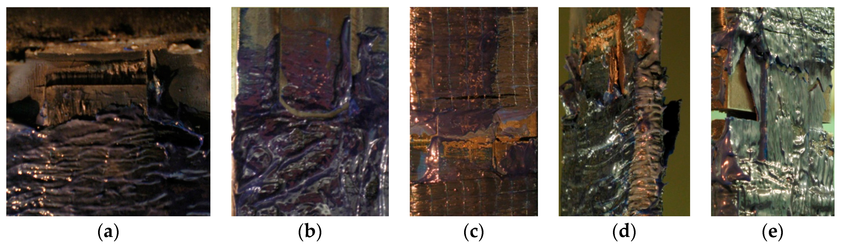
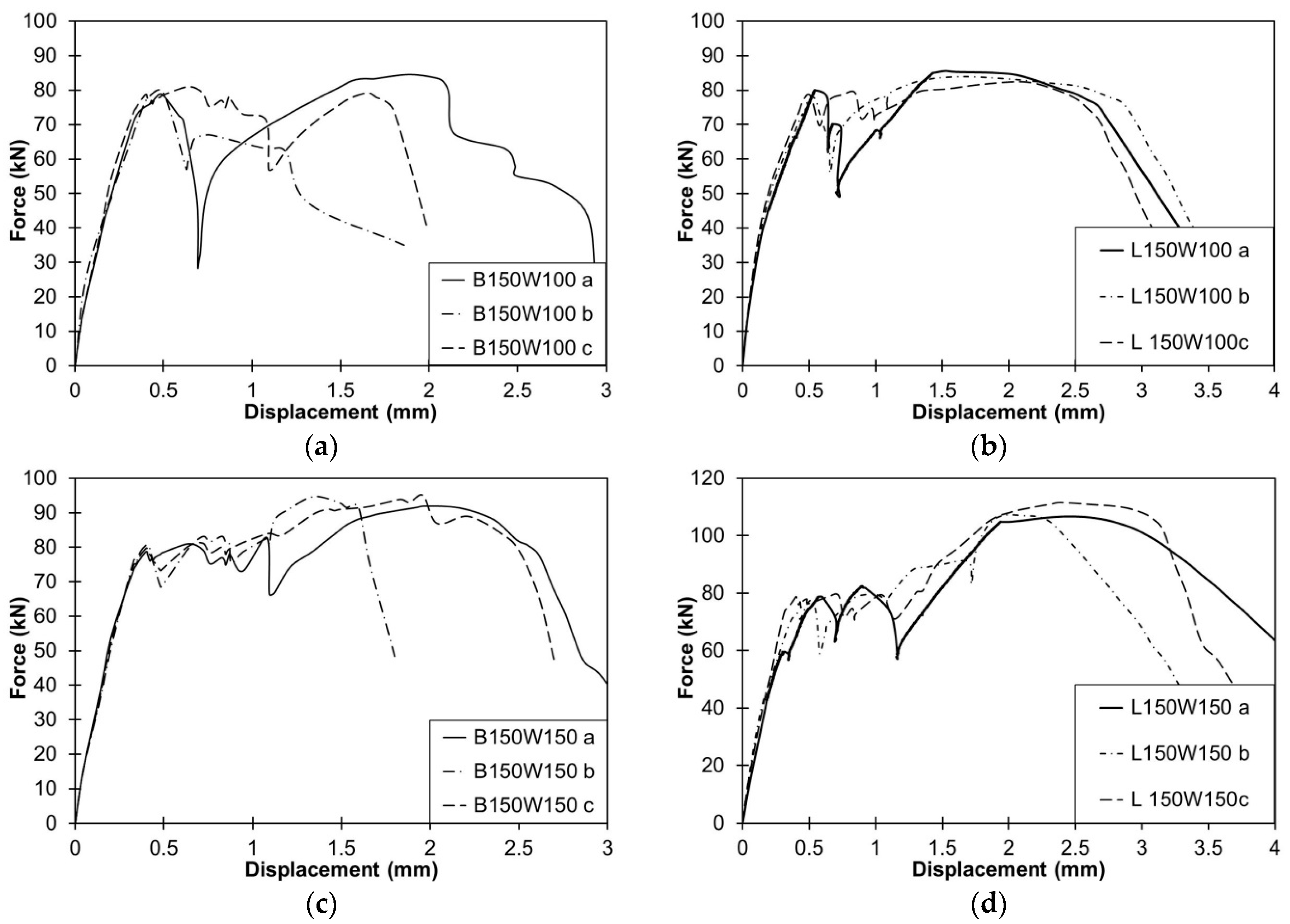
3.2. Wrapped Specimens

The experimental tests showed that the overall failure modes were very similar for both butt and lapped wrapped specimens. In particular, the failure modes were characterized by a sequence of nonlinear events. The former which experimentally observed was the adhesive failure, causing the initiation of slipping between the C-FRP strips and the steel elements (see Figure 5a,b). Once this phenomenon occurred, the interactions between the wrapped jacketing and the laminas allowed transferring the applied load from the steel plates to the C-FRP laminas by friction/adhesion. Increasing the applied displacements of the sliding actions of the C-FRP laminas within the wrapped jacket caused bending of the fibers, constituting the wrapped fabric in the transverse direction of the jacket (Figure 5c). During this behavioral phase, some specimens showed a secondary failure mode characterized by the unwrapping of the fabrics (Figure 5d), which impaired the joint capacity which dropped sharply. For all specimens the failure occurred when the jacketed anchorage was not able to restrain the C-FRP slip, thus resulting in large in-plane displacements due to the separation of the steel plates (see Figure 5e for both lapped and butt splices).
The experimental evidence indicated that the presence of wrapped jacketing at the anchorage allowed an improvement of performance, as is recognizable comparing Figure 6 to Figure 4. Indeed, all wrapped specimens exhibited a relatively large displacement capacity, which is substantially different from the brittle response of simply bonded splices. Indeed, the anchorage by wrapping allowed us to achieve higher C-FRP deformations prior to failure, delaying/preventing premature delamination. This result confirms the advantages of using wrapped fabrics to anchor bonded C-FRP strips, which has been previously demonstrated for applications on reinforced concrete structures [20]. The force-displacement response curves of all wrapped specimens were characterized by a saw-teeth profile. In this regard, it is interesting to highlight that during the tests, sudden slips with cracks in the resin of the wrapped anchorage were observed at each peak of the saw-teeth profile of the response curves. This feature can be explained by considering that the fibers of the fabric restrain the laminas and each sudden drop of resistance corresponds to the bonding failure of each one.
Table 4 summarizes the measured values of the conventional elastic and ultimate forces, and the displacement capacity μ = δu/δy is reported per test. As it can be noted, all wrapped specimens showed an ultimate strength larger than that experienced by the corresponding bonded specimens. The beneficial effect of the wrapped anchorage was largely observed for lapped splices with a jacketing width equal to 150 mm, which reached a mean ultimate strength larger than 70% of the strength of the unwrapped specimens. It should be noted that all specimens with a jacketing width equal to 150 mm showed an increase of ultimate strength significantly larger than those developed by specimens with 100 mm of jacketing width, as it can be easily observed comparing Figure 6a,b to Figure 6c,d, respectively.
Figure 6. Experimental response curves of C-FRP bonded splice joints with wrapping [20].
Technologies 04 00005 g006

4. Conclusions

The tests were carried out on both butt and lapped joint configurations using different arrangements for the end anchorage of the bonded composites, such as (i) external bonding and (ii) anchored jacketing with C-FRP sheets transversally wrapped to the longitudinal axis of the joints.
The results and discussions presented allow us to draft the following remarks:
  • The failure modes exhibited by both butt and lapped bonded splices were similar, characterized by a non-ductile response with a clear post-peak softening behaviour. The lapped specimens experienced a peak strength lesser than those of butt splices of about 11.2%.
  • Tests on unwrapped bonded splices showed that the ultimate bonding strength is practically insensitive to the bonding length of the strips in the range of 150 mm–250 mm. Hence, the limit of 200 mm proposed by the Italian code [15] is conservative.
  • Tests of wrapped splices highlighted the beneficial role of anchoring externally bonded FRP laminas in order to achieve larger deformations prior to failure, even though a more timely installation process is necessary.
  • The anchorage with wrapped C-FRP fabrics modified the post-elastic response of the splices by providing a pseudo-ductile behaviour, thus allowing a non-negligible ductility.
  • Similarly to the bonded specimens, the failure modes exhibited by both butt and lapped wrapped splices were substantially similar. As a consequence, it was not possible to observe a strict dependence of the failure mechanism on the splice geometry.

Acknowledgments

The authors are sincerely grateful to BASF-Italia spa and, in particular, Arch. Raffaele Hassler for providing all composite materials and assistance in the application of FRPs. They also wish to thank RFI (Rete Ferroviaria Italiana) and in particular: Eng. Antonio D’Aniello, former Director of the Department of Naples at RFI for his courtesy, cooperation and assistance throughout this research. Finally, authors would like to thank Eng. Giuseppe La Manna Ambrosino and Arch. Renata Marmo, for their help in the preparation of the specimens.

Author Contributions

All Authors equally contributed to the research described and discussed by this paper. All authors have read and approved the final manuscript.

Conflicts of Interest

The authors declare no conflict of interest.

References

  1. D’Aniello, M.; Portioli, F.; Fiorino, L.; Landolfo, R. Experimental investigation on shear behaviour of riveted connections in steel structures. Eng. Struct. 2011, 33, 516–531. [Google Scholar] [CrossRef]
  2. Sustainable bridges—European Research Project under the EU 6th Framework Programme, 2006. Available online: http://www.sustainablebridges.net/ (accessed on 4 February 2016).
  3. British Standards Institution (BSI). Hot Rolled Products of Non-Alloy Structural Steels. Technical Delivery Conditions for Non-Alloy Structural Steels; BS EN 10025-2:2004; BSI: London, UK, 2004. [Google Scholar]
  4. Zhao, X.; Zhang, L. State-of-the-art review on FRP strengthened steel structures. Eng. Struct. 2007, 29, 1808–1823. [Google Scholar] [CrossRef]
  5. Hollaway, L.C.; Cadei, J. Progress in the technique of upgrading metallic structures with advanced polymer composites. Prog. Struct. Eng. Mater. 2002, 4, 131–148. [Google Scholar] [CrossRef]
  6. Hollaway, L.C. Polymers, Fibres, Composites and the Civil Engineering Environment: A Personal Experience. Adv. Struct. Eng. 2010, 13, 927–960. [Google Scholar] [CrossRef]
  7. Song, K.; Zhang, Y.; Meng, J.; Green, E.C.; Tajaddod, N.; Li, H.; Minus, M.L. Structural Polymer-Based Carbon Nanotube Composite Fibers: Understanding the Processing–Structure–Performance Relationship. Materials 2013, 6, 2543–2577. [Google Scholar] [CrossRef]
  8. Guades, E.; Aravinthan, T.; Islam, M.; Manalo, A. A review on the driving performance of FRP composite piles. Compos. Struct. 2012, 94, 1932–1942. [Google Scholar] [CrossRef]
  9. Deng, J.; Lee, M.M.K. Adhesive bonding in steel beams strengthened with CFRP. Proc. Inst. Civ. Eng. Struct. Build. 2009, 162, 241–249. [Google Scholar] [CrossRef]
  10. Stratford, T.J.; Chen, J.F. Designing for tapers and defects in FRP-strengthened metallic structures. In Proceedings of the Designing for Tapers and Defects in Frp-Strengthened Metallic Structures, BBFS2005, Hong Kong, China, 7–9 December 2005.
  11. Kim, Y.J.; Brunell, G. Interaction between CFRP-repair and initial damage of wide flange steel beams subjected to three-point bending. Compos. Struct. 2011, 93, 1986–1996. [Google Scholar] [CrossRef]
  12. Bassetti, A.; Nussbaumer, A.; Hirt, M.A. Crack repair and fatigue life extension of riveted bridge members using composite materials. In Proceedings of the Crack Repair and Fatigue Life Extension of Riveted Bridge Members Using Composite Materials, ESE-IABSE-FIB, Sharm El Sheikh, Egypt, 26–30 March 2000.
  13. Xia, S.H.; Teng, J.G. Behaviour of FRP-to-steel bonded joints. In Proceedings of the International Symposium on Bond Behaviour of FRP in Structures, BBFS2005, Hong Kong, China, 7–9 December 2005.
  14. Teng, J.G.; Yu, T.; Fernando, D. Strengthening of steel structures with fiber reinforced polymer composites. J. Constr. Steel Res. 2012, 78, 131–143. [Google Scholar] [CrossRef]
  15. Istruzioni per la Progettazione, l’Esecuzione ed il Controllo di Interventi di Consolidamento Statico Mediante l’utilizzo di Compositi Fibrorinforzati. Available online: http://www.cnr.it/documenti/norme/IstruzioniCNR_DT200_2004.pdf (accessed on 4 February 2016).
  16. Cadei, J.M.C.; Stratford, T.J.; Hollaway, L.C.; Duckett, W.G. Strengthening Metallic Structures Using Externally Bonded Fibre-Reinforced Polymers; Publication C595, Construction Industry Research and Information Association (CIRIA): London, UK, 2004. [Google Scholar]
  17. Yang, Y.; Yue, Q.; Peng, F. Experimental research on bond behaviour of CFRP to steel. In Proceedings of the Experimental Study on Bond Behaviour between UHM CFRP Laminate and Steel, BBFS2005, Hong Kong, China, 7–9 December 2005.
  18. Mancusi, G.; Ascione, F. Performance at collapse of adhesive bonding. Compos. Struct. 2013, 96, 256–261. [Google Scholar] [CrossRef]
  19. ECCS-45. Recommended Testing Procedure for Assessing the Behaviour of Steel Elements under Cyclic Loads; European Convention for Constructional Steelwork: Brussels, Belgium, 1986. [Google Scholar]
  20. D’Aniello, M.; Portioli, F.; Landolfo, R. Lap shear tests on hot-driven steel riveted connections strengthened by means of C-FRPs. Compos. Part B Eng. 2014, 59, 140–152. [Google Scholar] [CrossRef]
  21. Fawzia, S.; Zhao, X.L.; Al-Mahaidi, R. Bond-slip models for double strap joints strengthened by CFRP. Compos. Struct. 2009, 92, 2137–2145. [Google Scholar] [CrossRef] [Green Version]
  22. Da Silva Lucas, F.M.; Rodriguesa, T.N.S.S.; Figueiredoa, M.A.V.; de Mouraa, M.F.S.F.; Chousal, J.A.G. Effect of adhesive type and thickness on the lap shear strength. J. Adhes. 2006, 82, 1091–1115. [Google Scholar] [CrossRef]

