
Evaluation of Calcium Fluoroaluminosilicate Based Glass Ionomer Luting Cements Processed Both by Conventional and Microwave Assisted Methods

Abstract
:1. Introduction
2. Materials and Methods

| Glass Code | SiO2 | Al2O3 | CaF2 | ZnO | SrO | MgO | Na3AlF6 | AlF3 | AlPO4 |
|---|---|---|---|---|---|---|---|---|---|
| G 021 | 3.5 | 1.4 | 0.5 | 0.5 | 0.2 | 0.1 | 0.2 | ||
| G 022 | 3.5 | 1.4 | 0.5 | 0.5 | 0.2 | 0.1 | 0.2 | ||
| G 023 | 3.5 | 1.4 | 0.5 | 0.5 | 0.2 | 0.1 | 0.2 |
2.1. Conventional Melting
2.2. Microwave Melting
2.3. Glass Characterization
2.4. Cements Preparation and Characterization
3. Results and Discussion
3.1. Glass Characterization
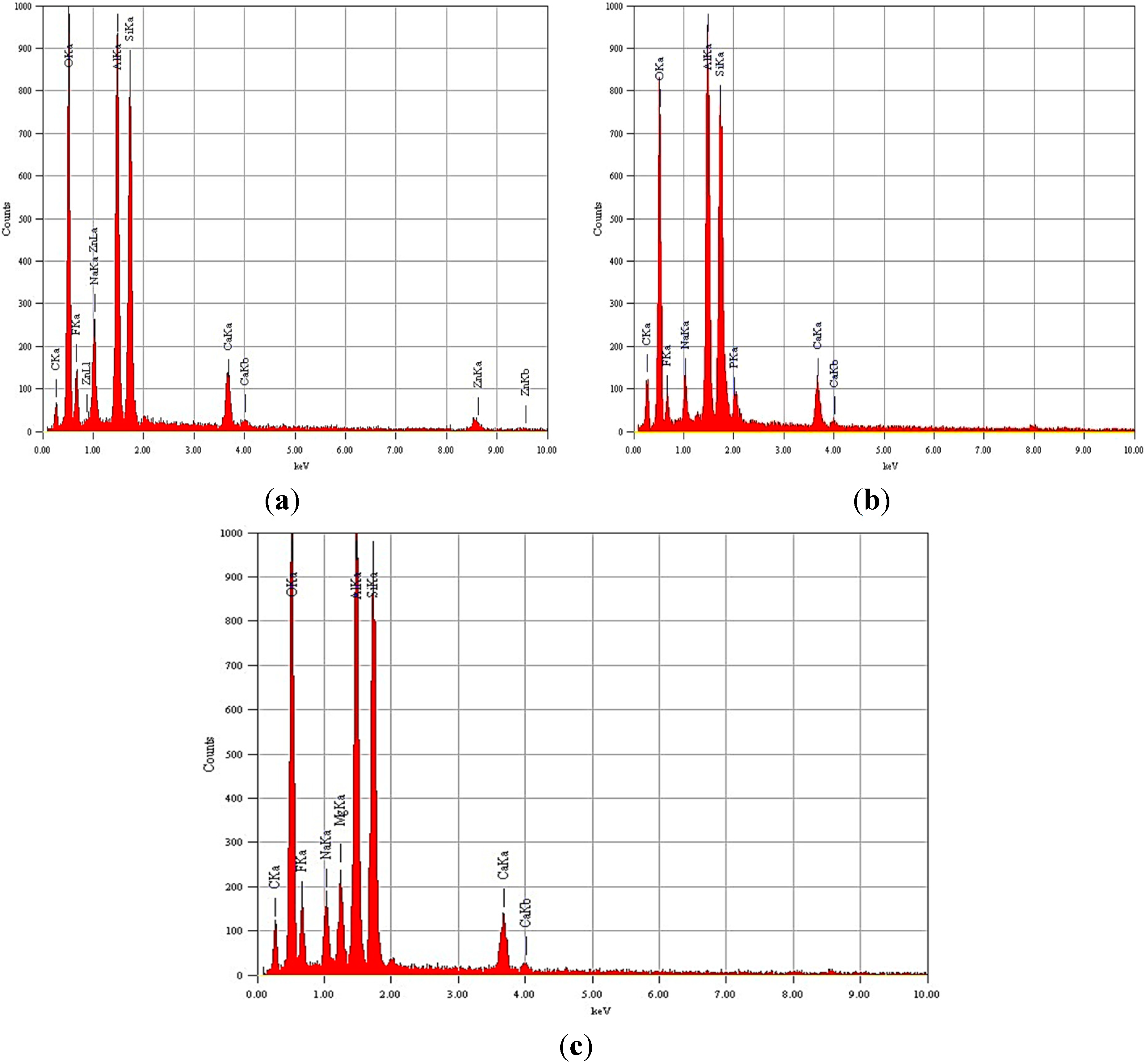
3.1.1. EDX Analysis
| Glass Code | O | F | Na | Al | Si | P | Ca | Zn | Sr | Mg |
|---|---|---|---|---|---|---|---|---|---|---|
| G 021 | 52.31 | 11.52 | 3.3 | 14.5 | 13.74 | 0.2 | 2.43 | 2.01 | -- | -- |
| G 022 | 53.45 | 7.94 | 3.85 | 16.41 | 14.04 | 1.58 | 2.73 | -- | -- | |
| G 023 | 53.18 | 11.23 | 4.04 | 13.55 | 12.38 | 0.24 | 2.21 | -- | -- | 3.16 |
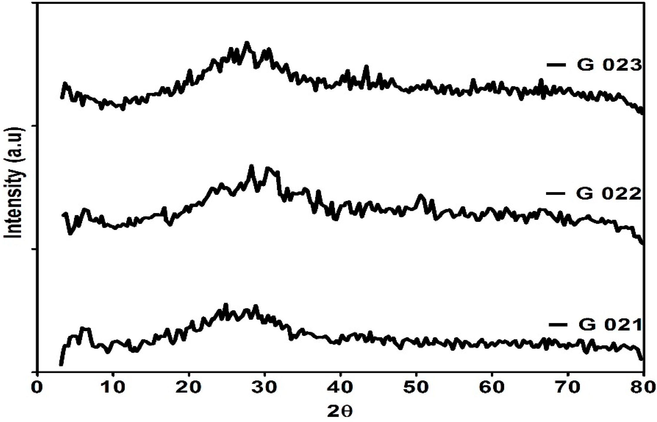
3.1.2. XRD Analysis
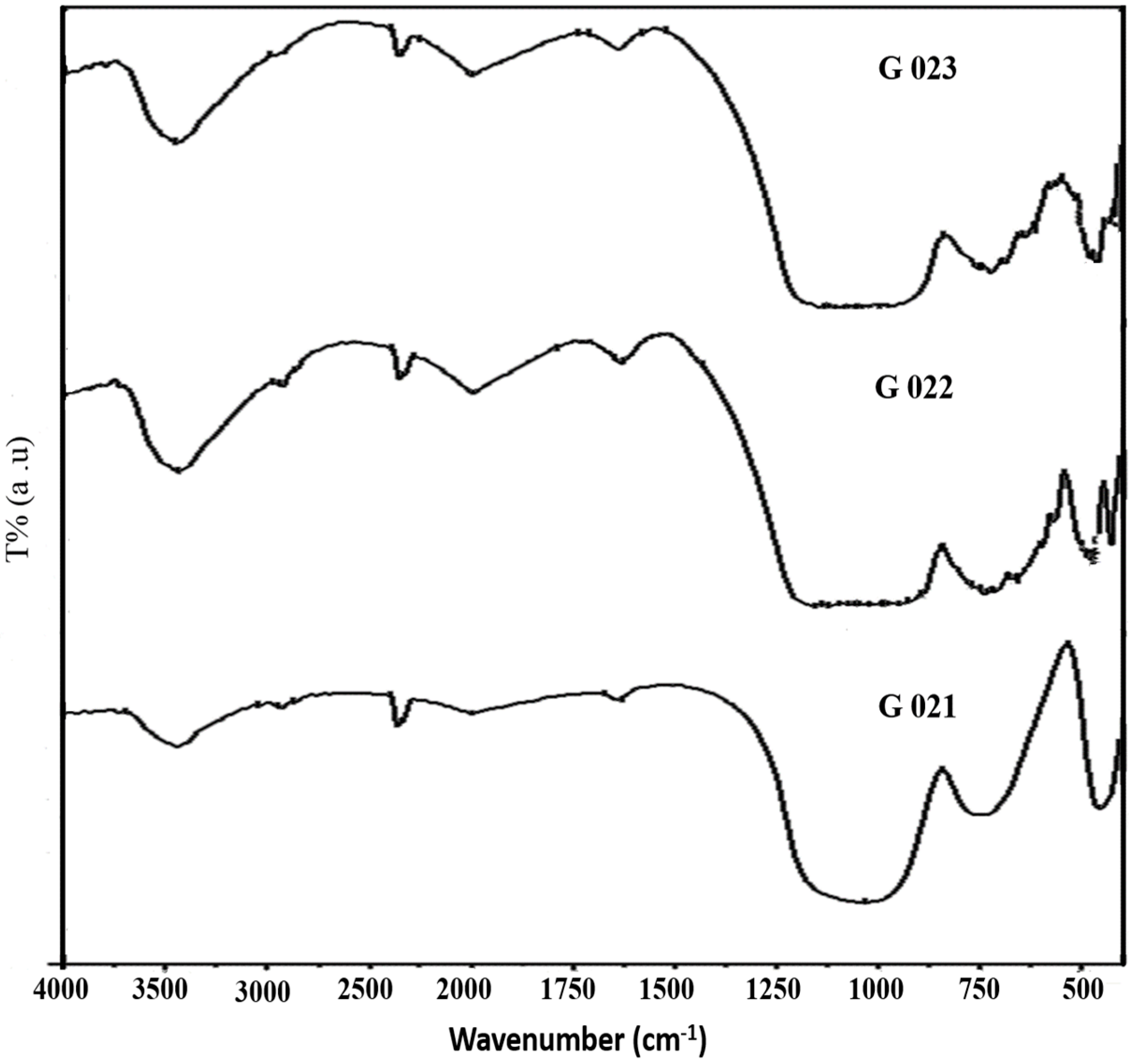
3.1.3. FT-IR Analysis


| G 021 | G 022 | G 023 | Accepted Value/Range | Assignment |
|---|---|---|---|---|
| 1030 | 1031 | 1055 | 1000–1100 | υAS Si-O-Si |
| 748 | 742 | 748 | 730 | υS Si-O-Si |
| 453 | 464 | 457 | 460 | υB Al-O-Al or Al-O-Si |
3.1.4. Particle Size Analysis
| Glass | Diameter at 10% d10 (µm) | Diameter at 50% d50 (µm) | Diameter at 90% d90 (µm) | Mean Diameter (µm) |
|---|---|---|---|---|
| Glass 0 21 | 1.20 | 3.89 | 35.07 | 10.48 |
| Glass 0 22 | 0.66 | 1.98 | 4.09 | 2.19 |
| Glass 0 23 | 0.87 | 2.16 | 5.21 | 2.65 |
3.2. Cement Properties
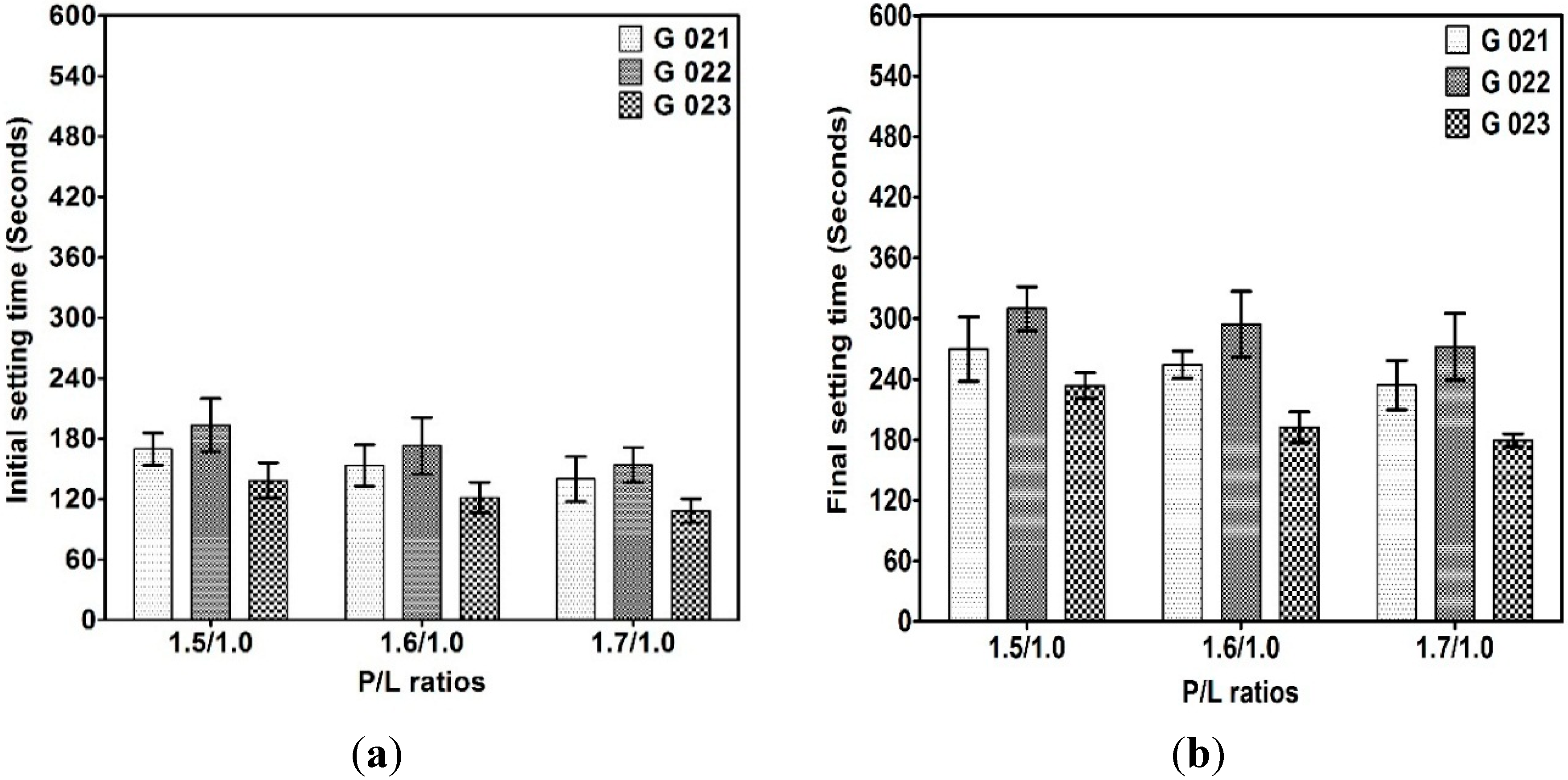
3.2.1. Initial and Final Setting Times


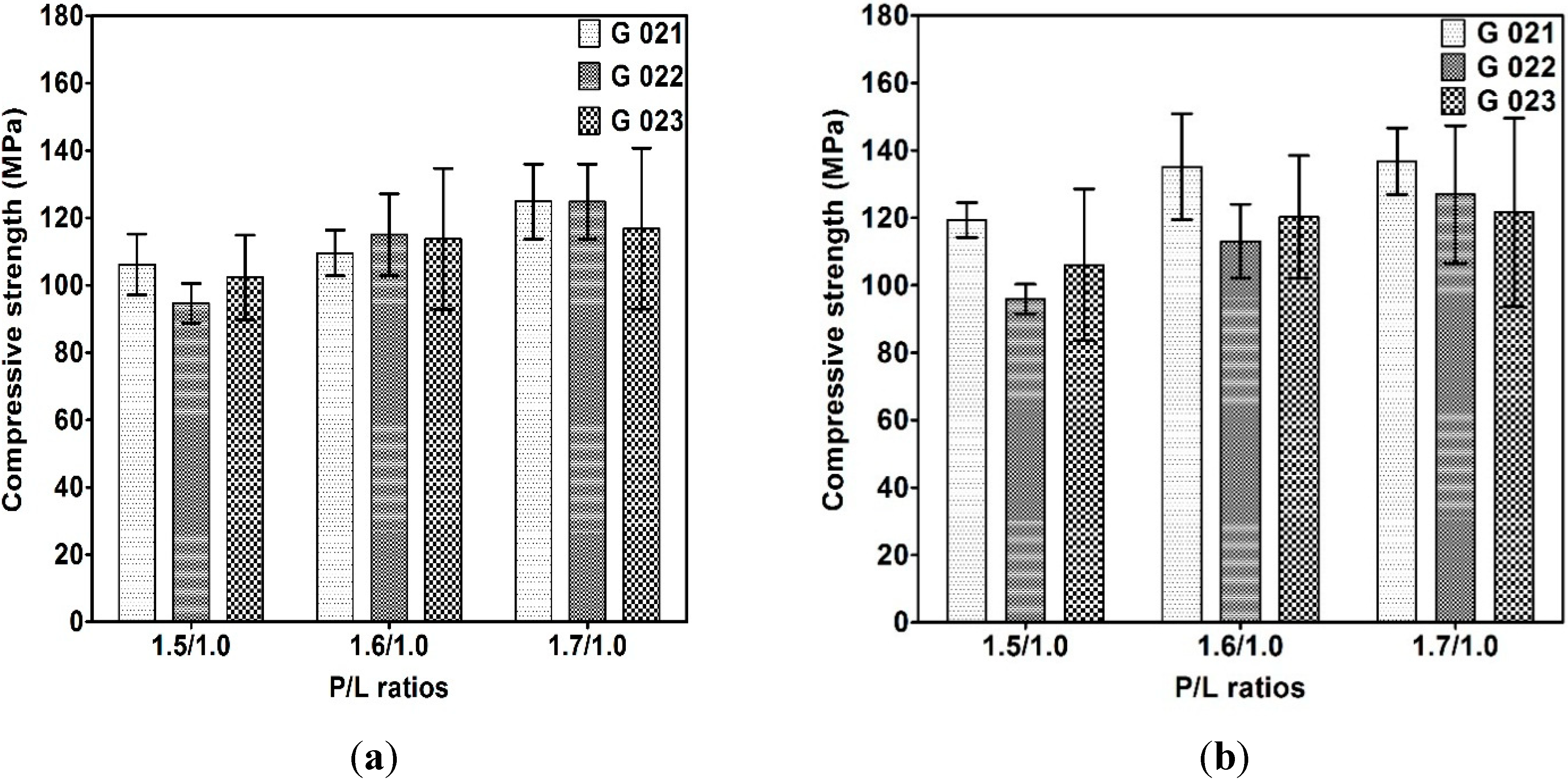
3.2.2. Compressive Strength
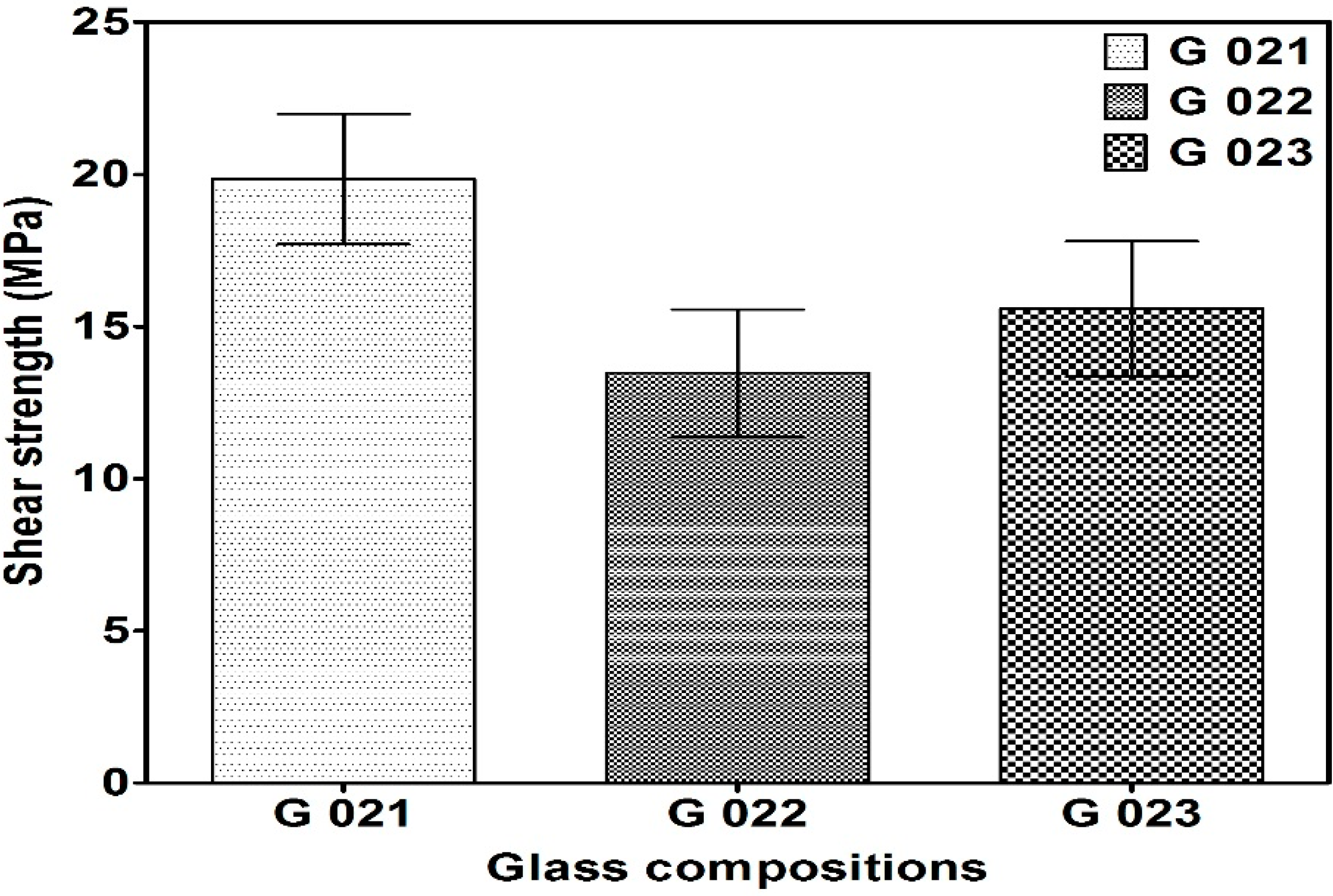
3.2.3. Shear Strength
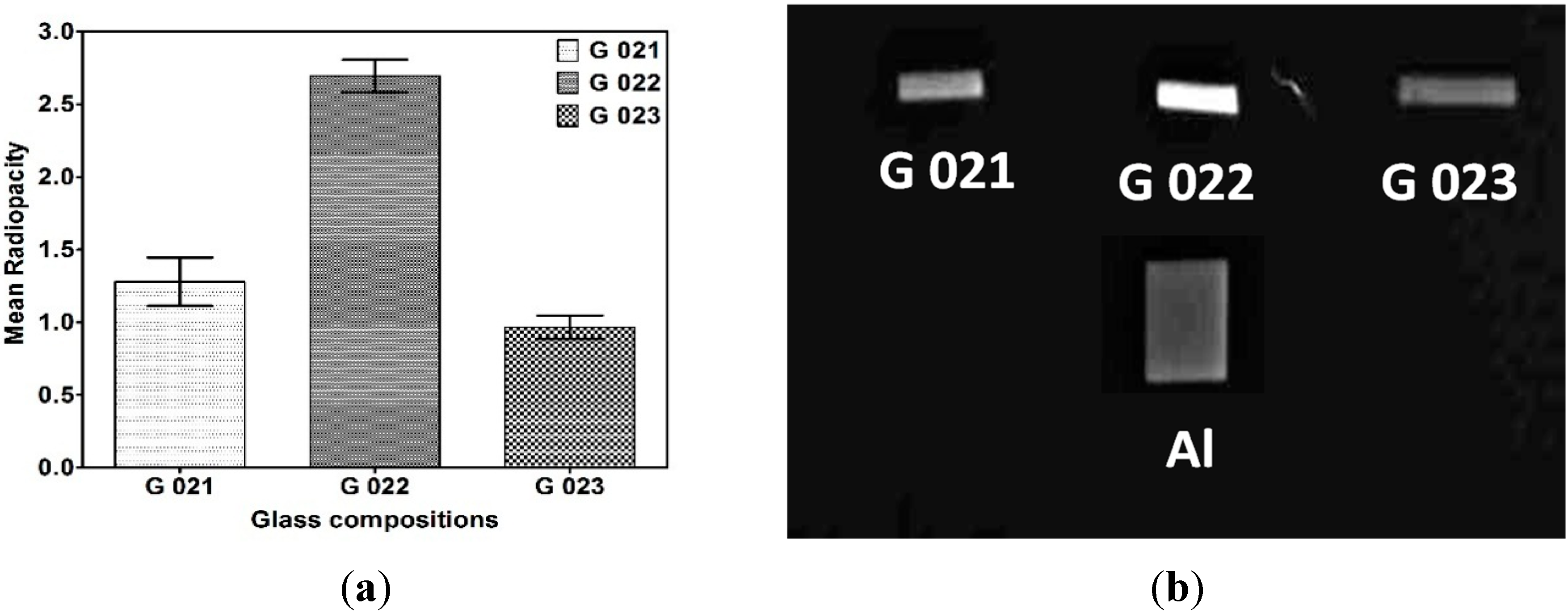
3.2.4. Radiopacity
4. Conclusions
Acknowledgments
Author Contributions
Conflicts of Interest
References
- Edward, E.H. Dental cements for definitive luting: A review and practical clinical considerations. Dental Clin. North Am. 2007, 51, 643–658. [Google Scholar] [CrossRef]
- Braden, M.; Clarke, R.L.; Nicholson, J.; Parker, S. Polymeric Dental Materials; Springer-Verlag: Berlin/Heidelberg, Germany, 1997. [Google Scholar]
- Smith, D.C. Development of glass ionomer cements. Biomaterials 1998, 19, 467–478. [Google Scholar] [CrossRef] [PubMed]
- Wilson, A.D.; McLean, J.W. Glass Ionomer Cement; Quintessence Publishing Co.,Inc.: Hanover Park, IL, USA, 1988. [Google Scholar]
- McKinney, J.E.; Antonucci, J.M.; Rupp, N.W. Wear and microhardness of silver sintered glass ionomer cement. J. Dent. Res. 1988, 67, 831–835. [Google Scholar] [CrossRef] [PubMed]
- Griffin, S.G.; Hill, R.G. Glass composition influence on glass polyalkenoate cement mechanical properties. J. Non Cryst. Solids 1996, 196, 255–259. [Google Scholar] [CrossRef]
- Kent, B.E.; Lewis, B.G.; Wilson, A.D. Glass ionomer cement formulations: I. The preparation of novel fluoroaluminosilicate glasses high in fluorine. J. Dent. Res. 1979, 58, 1607–1619. [Google Scholar] [CrossRef] [PubMed]
- Mount, G.J. Glass ionomer cements: Past, present and future. Oper. Dent. 1994, 19, 82–90. [Google Scholar] [PubMed]
- De la Macorra, J.C.; Pradies, G. Conventional and adhesive luting cements. Clin. Oral Investig. 2002, 6, 198–204. [Google Scholar]
- Attar, N.; Tam, L.E.; McComb, D. Mechanical and physical properties of contemporary dental luting cements. J. Prosthet. Dent. 2003, 89, 127–134. [Google Scholar] [CrossRef] [PubMed]
- Rosenstiel, S.F.; Land, M.F.; Crispin, B.J. Dental luting agents: A review of the current literature. J. Prosthet. Dent. 1998, 80, 280–301. [Google Scholar] [CrossRef] [PubMed]
- Tsuge, T. Radiopacity of conventional, resin modified glass ionomer, and resin based luting materials. J. Oral Sci. 2009, 15, 223–230. [Google Scholar] [CrossRef]
- Bertolini, M.J.; Zaghete, M.A.; Gimenes, R.; Padovani, G.C.; Cruz, C.A.S. Preparation and evaluation of an experimental luting glass ionomer cement to be used in dentistry. J. Mater. Sci. 2009, 20, 1781–1785. [Google Scholar]
- Bertolini, M.J.; Regina, G.P.D.; Zaghete, M.A.; Gimenes, R. Evaluation of glass ionomer cements properties obtained from niobium silicate glasses prepared by chemical process. J. Non-Cryst. Solids 2005, 351, 466–471. [Google Scholar] [CrossRef]
- Cestari, A.; Bandeira, L.C.; Calefi, P.S.; Nassar, E.J.; Ciuffi, K.J. Preparation of calcium fluoroaluminosilicate glasses containing sodium and phosphorus by the nonhydrolytic sol–gel method. J. Alloys Comp. 2009, 472, 299–306. [Google Scholar] [CrossRef]
- Bertolini, M.J.; Zaghete, M.A.; Gimenes, R.; Raphael, F.D.; Vaz, L.G. Preparation of new glass systems by the polymeric precursor method for dental applications. J. Non-Cryst. Solids 2004, 344, 170–175. [Google Scholar] [CrossRef]
- Subrata, S.; Ram Mohan, V.C.; Delregno, G.E. Method of Microwave Processing Ceramics and Microwave Hybrid Heating System for Same. US 2007/0023971 A1, 1 February 2007. [Google Scholar]
- American National Standard/American Dental Association. Specification No. 96, Dental Water Based Cements; American National Standard/American Dental Association: Chicago, IL, USA, 1995. [Google Scholar]
- Boyd, D.; Towler, M.R.; Watts, S.; Hill, R.G.; Wren, A.W.; Clarkin, O.M. The role of Sr2+ on the structure and reactivity of SrO–CaO–ZnO–SiO2 ionomer glasses. J. Mater. Sci. 2008, 19, 953–957. [Google Scholar]
- Wren, A.; Clarkin, O.M.; Laffir, F.R.; Ohtsuki, C.; Kim, I.Y.; Towler, M.R. The effect of glass synthesis route on mechanical and physical properties of resultant glass ionomer cements. J. Mater. Sci. 2009, 20, 1991–1999. [Google Scholar]
- De Maeyer, E.A.P.; Verbeeck, R.M.H.; Vercruysse, C.W.J. Reactivity of fluoride-containing calcium aluminosilicate glasses used in dental glass-ionomer cements. J. Dent. Res. 1998, 77, 2005–2011. [Google Scholar] [CrossRef] [PubMed]
- Chen, W.S.; Monroe, E.A.; Condrate, R.A.; Guo, Y.M. An investigation of the hardening process for several phosphate glass—Containing cements. J. Mater. Sci. 1993, 4, 111–116. [Google Scholar]
- De Maeyer, E.A.P.; Verbeeck, R.M.H.; Vercruysse, C.W.J. Infrared spectrometric study of acid-degradable glasses. J. Dent. Res. 2002, 81, 552–555. [Google Scholar] [CrossRef] [PubMed]
- Gu, Y.W.; Yap, A.U.J.; Cheang, P.; Kumar, R. Spheroidization of glass powders for glass ionomer cements. Biomaterials 2004, 25, 4029–4035. [Google Scholar] [CrossRef] [PubMed]
- Powers, J.M.; Sakaguchi, R.L. Craig’s Restorative Dental Materials, 12th ed.; Mosby: Maryland Heights, MO, USA, 2006. [Google Scholar]
- Crisp, S.; Merson, S.A.; Wilson, A.D. Modification of ionomer cements by the addition of simple metal salts. Ind. Eng. Chem. Prod. Res. Dev. 1980, 19, 403–408. [Google Scholar] [CrossRef]
- Barra, E.D.; Hill, R.G. Influence of alkali metal ions on the fracture properties of glass polyalkenoate (ionomer) cements. Biomaterials 1998, 19, 495–502. [Google Scholar] [CrossRef] [PubMed]
- Neve, A.D.; Piddock, V.; Combe, E.C. The effect of glass heat treatment on the properties of a novel polyalkenoate cement. Clin. Mater. 1993, 12, 113–115. [Google Scholar] [CrossRef] [PubMed]
- Deb, S.; Nicholson, J.W. The effect of strontium oxide in glass—Ionomer cements. J. Mater. Sci. 1999, 10, 471–474. [Google Scholar]
- Boyd, D.; Towler, M.R. The effect of strontium on the rheology and mechanical properties of Zinc based glass polyalkenoate cements. Eur. Cells Mater. 2006, 11, 26. [Google Scholar]
- Crisp, S.; Prosser, H.J.; Wilson, A.D. An infrared spectroscopic study of cement formation between metal oxides and aqueous solutions of poly (acrylic) acid. J. Mater. Sci. 1976, 11, 36–48. [Google Scholar] [CrossRef]
- Prentice, L.H.; Tyas, M.J.; Burrow, M.F. The effect of particle size distribution on an experimental glass-ionomer cement. Dent. Mater. 2005, 21, 505–510. [Google Scholar] [CrossRef] [PubMed]
- Angeles, M.; Lorente, C.; Godin, C.; Meyer, J.M. Mechanical behavior of glass ionomer cements affected by long term storage in water. Dent. Mater. 1994, 10, 37–44. [Google Scholar] [CrossRef] [PubMed]
- Piwowarczyk, A.; Lauer, H.C. Mechanical properties of luting cements after water storage. Oper. Dent. 2003, 28, 535–542. [Google Scholar] [PubMed]
- Yamazaki, A.; Hibino, Y.; Honda, M.; Nagasawa, Y.; Hasegawa, Y.; Omatsu, J.; Yamaga, T.; Nakajima, H. Effect of water on shear strength of glass ionomer cements for luting. Dent. Mater. J. 2007, 26, 708–712. [Google Scholar] [CrossRef] [PubMed]
- Fonseca, R.B.; Branco, C.A.; Soares, P.V.; Correr-Sobrinho, L.; Haiter-Neto, F.; Fernandes-Neto, A.J.; Soares, C.J. Radiodensity of base, liner and luting dental materials. Clin. Oral Investig. 2006, 10, 114–118. [Google Scholar] [CrossRef] [PubMed]
© 2015 by the authors; licensee MDPI, Basel, Switzerland. This article is an open access article distributed under the terms and conditions of the Creative Commons Attribution license (http://creativecommons.org/licenses/by/4.0/).
Share and Cite
P., N.U.; Srinivasan, K.K.; Adhikari, A.V.; Satapathy, L.N. Evaluation of Calcium Fluoroaluminosilicate Based Glass Ionomer Luting Cements Processed Both by Conventional and Microwave Assisted Methods. Technologies 2015, 3, 58-73. https://doi.org/10.3390/technologies3020058
P. NU, Srinivasan KK, Adhikari AV, Satapathy LN. Evaluation of Calcium Fluoroaluminosilicate Based Glass Ionomer Luting Cements Processed Both by Conventional and Microwave Assisted Methods. Technologies. 2015; 3(2):58-73. https://doi.org/10.3390/technologies3020058
Chicago/Turabian StyleP., Nagaraja Upadhya, Keloth Kaitheri Srinivasan, A. Vasudeva Adhikari, and Lakshmi Narayan Satapathy. 2015. "Evaluation of Calcium Fluoroaluminosilicate Based Glass Ionomer Luting Cements Processed Both by Conventional and Microwave Assisted Methods" Technologies 3, no. 2: 58-73. https://doi.org/10.3390/technologies3020058