1. Introduction
Morphing wing devices are capable of adapting their geometry in order to achieve a wide range of increased performance [
1,
2,
3,
4]. In the case of morphing aircraft, such goals include, among the others, enhanced aerodynamic efficiency or alleviating gusts, with a beneficial impact on aircraft fuel consumption and flight range.
Conventional aircraft structures are typically conceived in order to intrinsically exhibit specific aeroelastic responses. The wing architecture derives, for instance, from well-defined aerodynamic studies and aeroelastic predictions under several load cases. The parametric study of flutter is a crucial step when dealing with the design of conventional A/C movable surfaces (flaps, ailerons, rudder, etc.), in an attempt to avoid either bell-shaped or sharp flutter instabilities. In the case of morphing wings, these aspects are even more critical due to the extremely complex and largely distributed architectures, including much more elements than conventional counterparts. Due to the unconventional arrangement and their potential mutual interaction, especially in the case of malfunctioning or failure conditions, their aeroelastic assessment appears to be a fundamental step since the preliminary design stages of aircraft wings equipped with morphing systems. This inevitably influences mass and stiffness properties of the morphing device along with the related actuation requirements.
Hinged mechanisms [
5], an alternative to compliant systems [
6], give rise to important design challenges. The increased number and kind of parts and the smaller and more diffused components introduce new needs and sometimes exasperate aspects that were until now, under control in the design of conventional wing structures. In particular, the associated safety and reliability issues may affect the aeroelastic response of the entire wing. A total loss of the morphing system due to kinematic failures, for instance, may result in free unforced oscillations, which may potentially lead to flutter phenomena involving the entire aircraft. It is then, not surprising that failure scenarios, such as the rupture of primary hinges and/or actuation links of movable morphing parts, which may dramatically impact the aircraft aeroelastic stability margins with catastrophic safety-related consequences, are increasingly becoming a topic of interest for the purposes of increasing aircraft flight stability of aircraft wings equipped with morphing technology.
In the literature, a way of solving these design complications is to reduce the main problem to its constituent sub-components. These imply that the aircraft is structurally designed such that it can be assured that the target morphing shapes are reached or can carry out the aerodynamic shape optimization to identify the optimum configurations for the morphing of the wings [
7]. An additional aspect of interest concerns the aerodynamics and structure interaction, to prevent aeroelastic instability during flight. The design strategy of partitioning the design problem into distinct subject areas leads the way to the development of several morphing aircraft concepts. However, it should be noted that a more comprehensive approach could emphasize the potential structural improvements in terms of weight and number of components while maintaining the requested aerodynamic benefits.
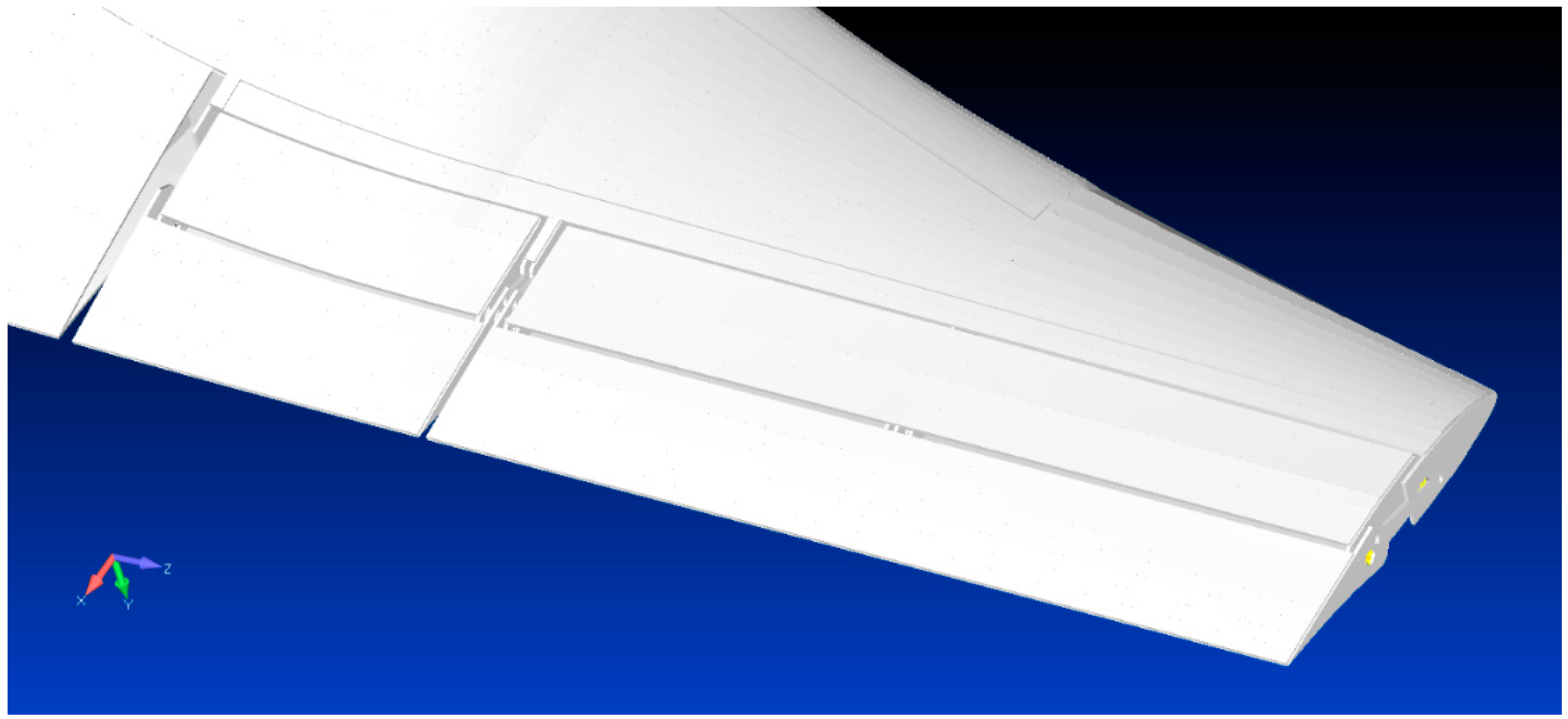
In order to check the validity of these considerations, the authors chose, as a reference application, the aeroelastic model of a regional aircraft equipped with morphing winglets,
Figure 1 [
8,
9]. A suitable aerodynamic model based on 3D flat panels was implemented for the evaluation of the unsteady aerodynamic influence coefficients through doublet lattice method. Linear and surface spline functions were used to interpolate modal displacements along the normal of the aerodynamic panels and to evaluate the generalized aerodynamic forces.
The winglet conceptual design is based on the “finger-like” mechanism that the same authors conceived and validated on full-scale aileron devices [
10,
11] and morphing wing trailing edge [
12,
13,
14]. Ref. [
15,
16,
17] presents the enhanced (estimated about 3%) aerodynamic performance assured by the physical integration of morphing winglets on a next-generation regional aircraft.
2. Morphing Winglet Concept
2.1. Scope and Reference Geometries
Research on morphing aircraft structures aims to wing design optimization by considering co-factors involving both aerodynamics and structures. Morphing devices applications can bring several benefits in terms of aircraft performance, as the current literature shows. Among such applications, shape-changing winglets can enhance the lift-on-drag ratio in off-design conditions and reduce aerodynamic wing loads by providing adapted geometry and wing lift distribution throughout the A/C flight envelope. This can potentially lead the way toward the adaptive winglets application to next-generation aircraft. For that purpose, the architectural design concept of a multi-modal morphing winglet is collocated within the scope of Clean Sky 2 Regional Aircraft IADP (Innovative Aircraft Demonstrator Platform), made in compliance with the pertinent requirements proposed by the airworthiness regulations.
In the adaptive winglet conceptual design, it is assumed that:
Morphing winglet system chord is equal to the 40% of the mean winglet chord (MWC);
Deflection is within the range [−15°, +10°] (where deflections are considered negative if reduce root bending moment).
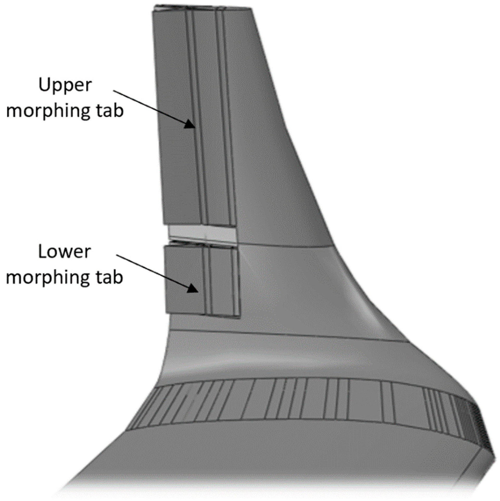
Morphing is ensured by a dedicated mechanism composed by movable surfaces (namely, upper and lower tabs), whose deflection is driven by dedicated actuators [
15,
16,
17]. By rotating respectively and independently upper and lower tabs, two possible configurations of the adaptive winglet can be achieved, as shown in
Figure 2.
The separate control of the downward deflections of the control surfaces during climb and cruise phases improves the lift-on-drag ratio. On the other hand, aerodynamic assessments showed that changing the angles between inner and outer winglet may potentially bring many other aerodynamic benefits [
19].
2.2. Morphing Winglet Architecture
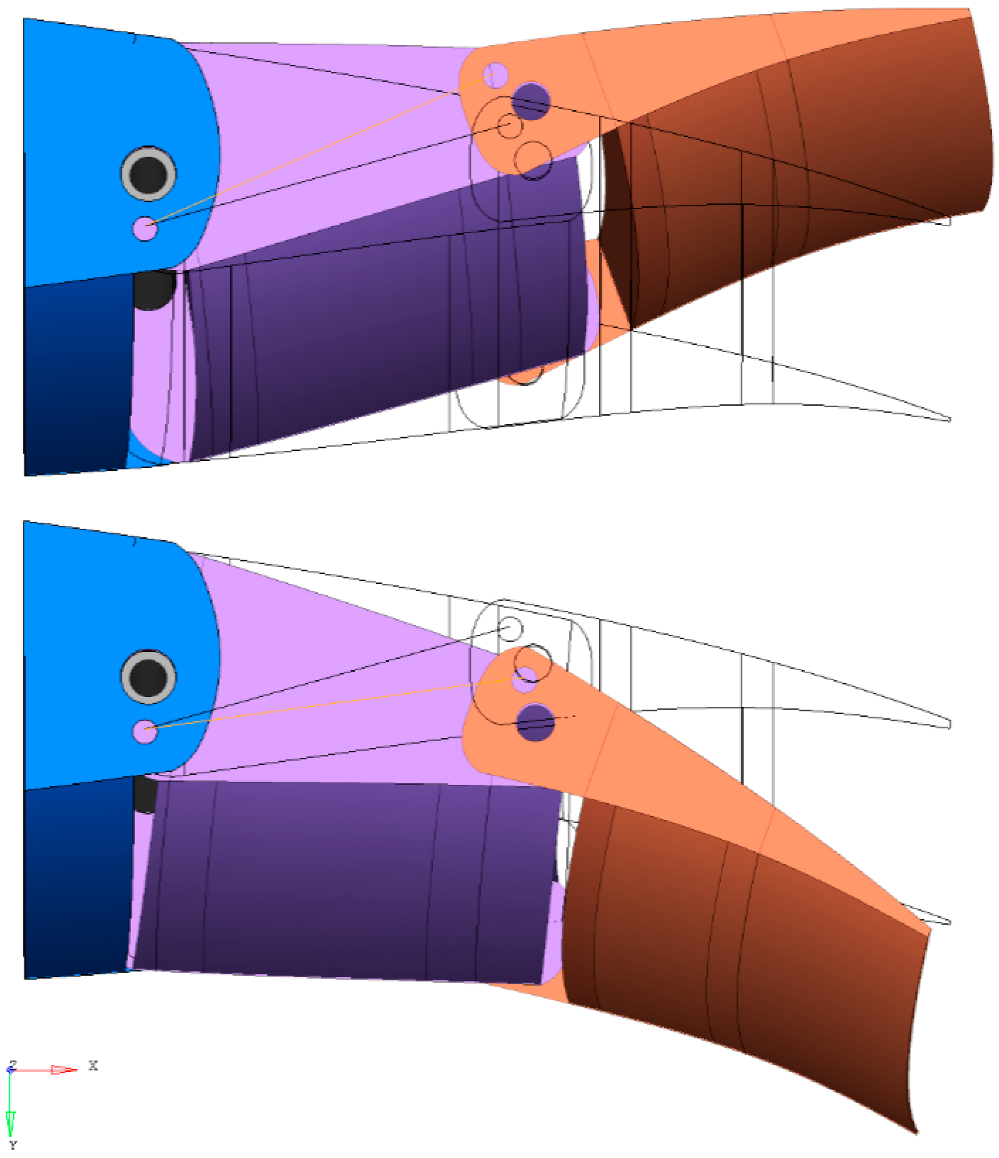
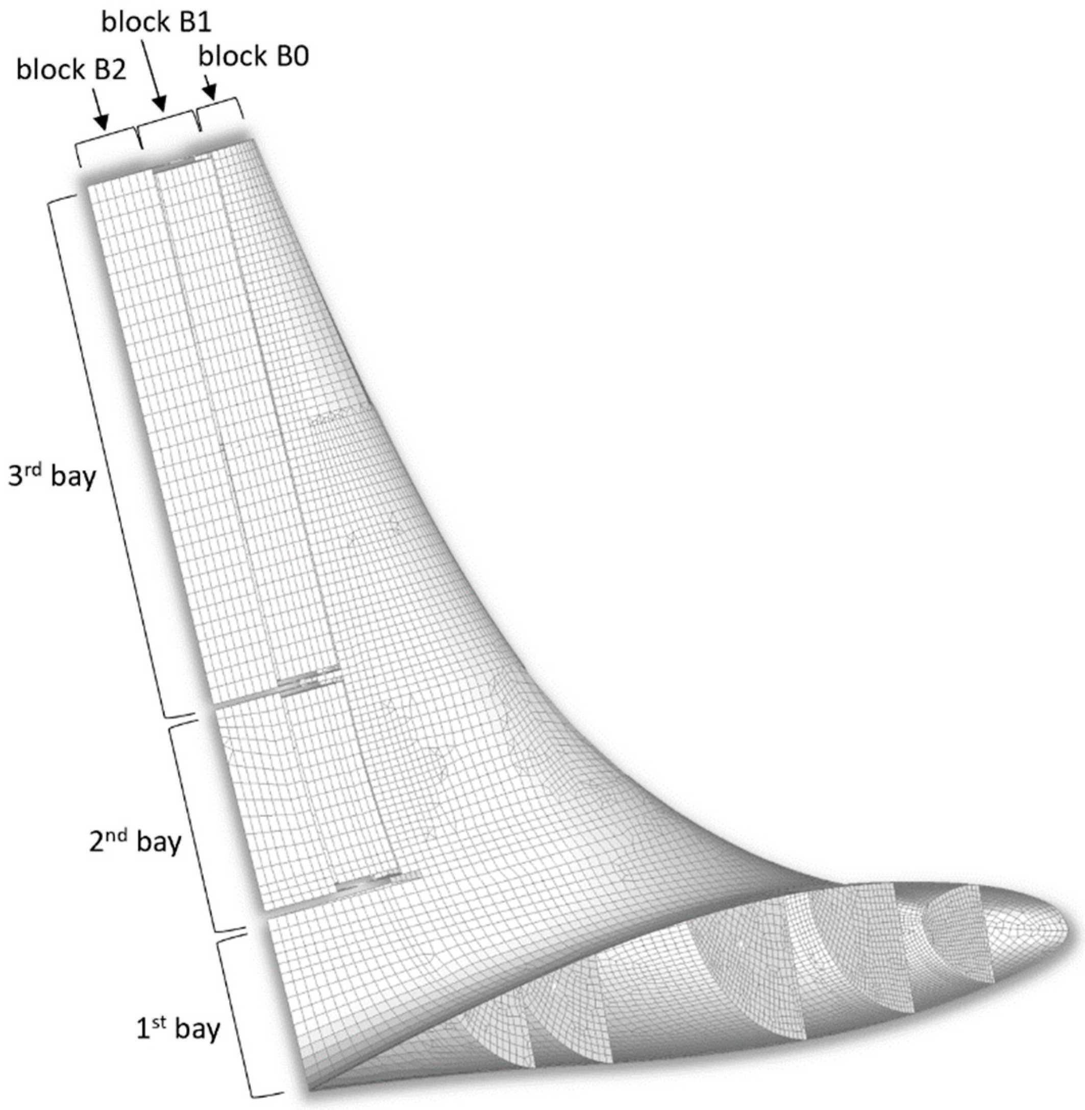
The main structure of the winglet fully embeds the adaptive architecture, and was conceived to reduce the induced drag by modulating the distribution of span-wise aerodynamic loads. Moreover, such architecture allows also for load alleviation functions, by means of negative deflections of the movable parts. Winglet morphing capabilities are ensured by the relative rotations of three adjacent blocks, namely B0, B1, and B2, connected to each other by means of relative hinges,
Figure 3 and
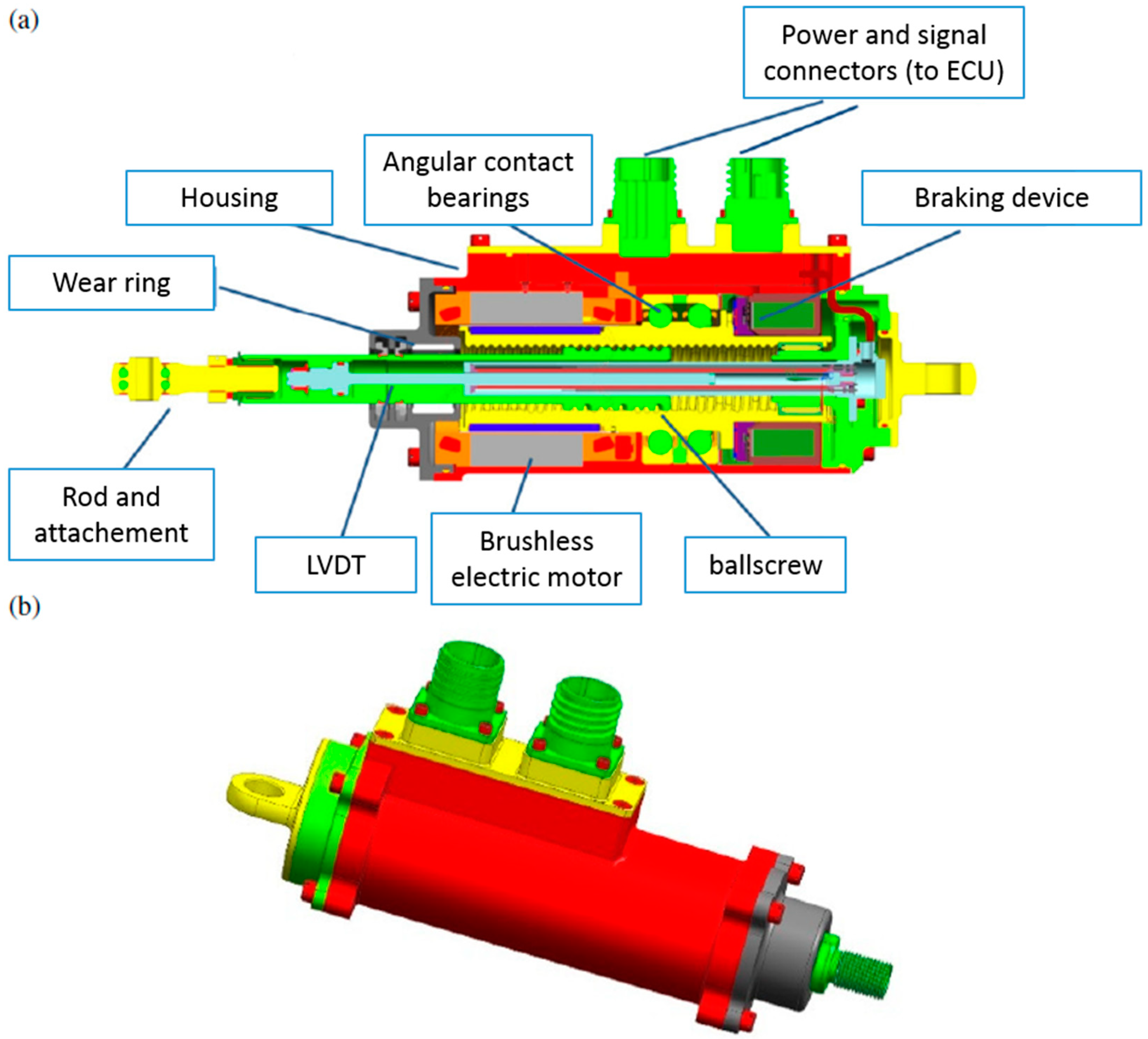
Figure 4. The term “block” refers to the structural part including two segments connected by a spar box. Both lower and upper electromechanical linear actuators are in B1; in order to activate morphing, each actuator induces B1 rotation around its hinge axis through a rigid rod. A large part of the incoming loads places stress on such a structural element, making its design very crucial,
Figure 5 shows the electro mechanical actuators (EMA) chosen for the morphing activation.
The system, conceived in such a way, results in a single degree of freedom—the rotation of consecutive blocks occurs according to a proper gear ratio. B0 is also defined as “dead box” since it is rigidly connected to the winglet rear spar (unmorphing box). The shape-changing ability of the morphing winglet is ensured by a segmented skin arrangement covering both the upper and the lower trailing edge. More in detail, two panels of skin are properly connected to the ribs edges and spars underneath it. The materials considered for movable and non-movable parts were different; in particular:
Carbon-fiber, for the non-movable part;
Aluminum alloy, for the movable parts.
Material mechanical properties are reported in
Table 1:
The overall weight of the device was estimated below 50 Kg.
3. Fault and Hazard Assessment of the Morphing Winglet
3.1. Safety Analysis: General Approach
Typically, the safety analysis of aircraft devices consists of three major phases, i.e., fault and hazard assessment (FHA), preliminary system safety assessment (PSSA), and system safety assessment (SSA). In the FHA, a qualitative examination of the faults is carried out to identify the associated risks. The severity of these hazards is classified to determine the maximum tolerable probability of occurrence. As a consequence of the probabilities assigned to each identified failure, safety requirements of the basic components are thus calculated. Such quantitative analysis is usually referred to as a fault tree (FT) analysis.
A morphing winglet device is generally classified as a “safety-critical” structure. This means that any loss of the system function could potentially result in “catastrophic” events for the aircraft. Flutter is surely the most important risk and requires dedicated assessments since the preliminary design stages [
21]. As a result, its probability of occurrence must be proved below the threshold value of <10
−9 per flight hour.
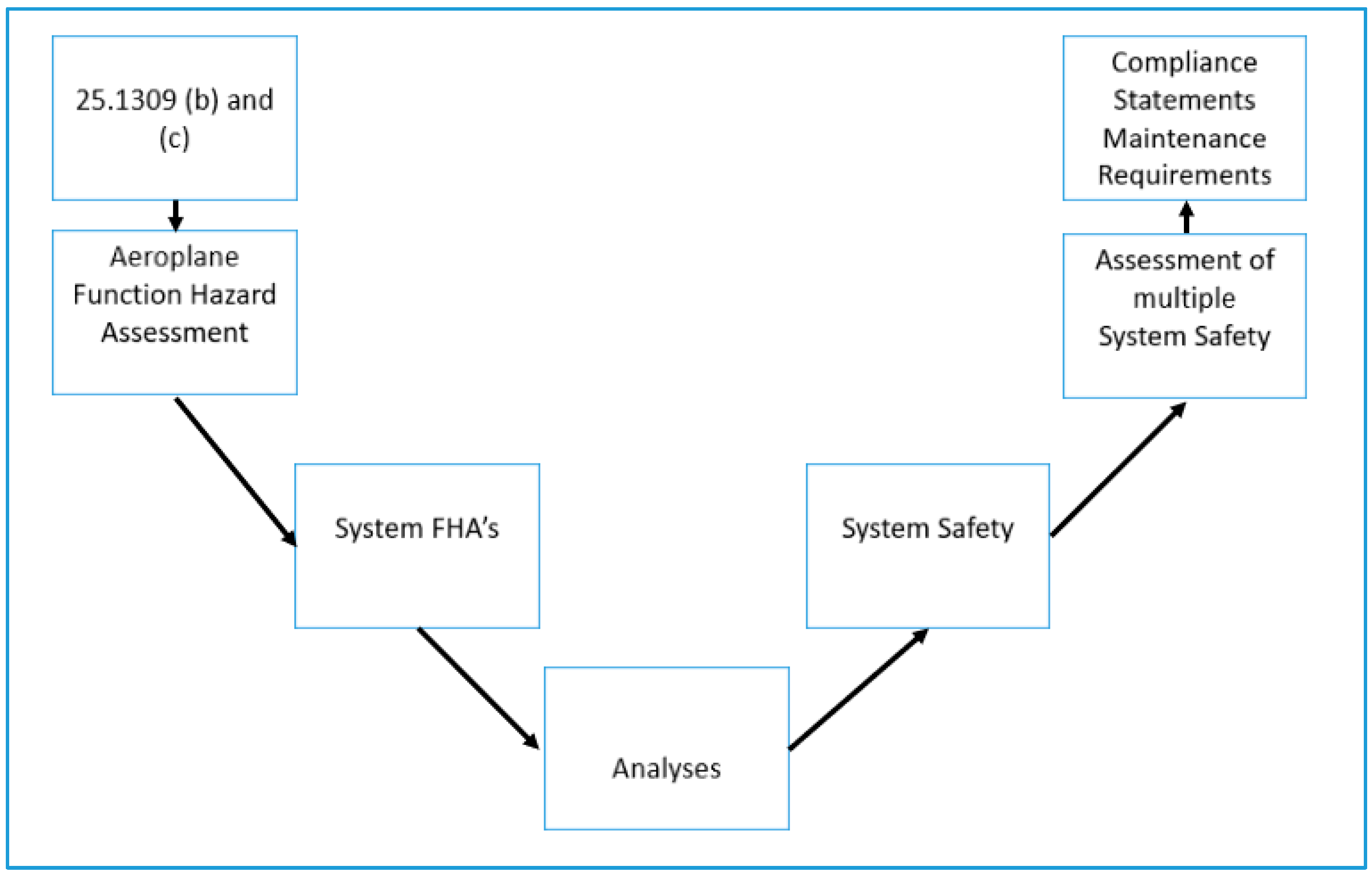
The main drivers in the safety-driven design of morphing systems are the already-mentioned CS-25 regulations as well as the Aerospace Recommended Practices SAE ARP 4754a [
22] and SAE ARP4761 [
23]. The CS-25 safety regulation requires the general safety assessment process shown in
Figure 6.
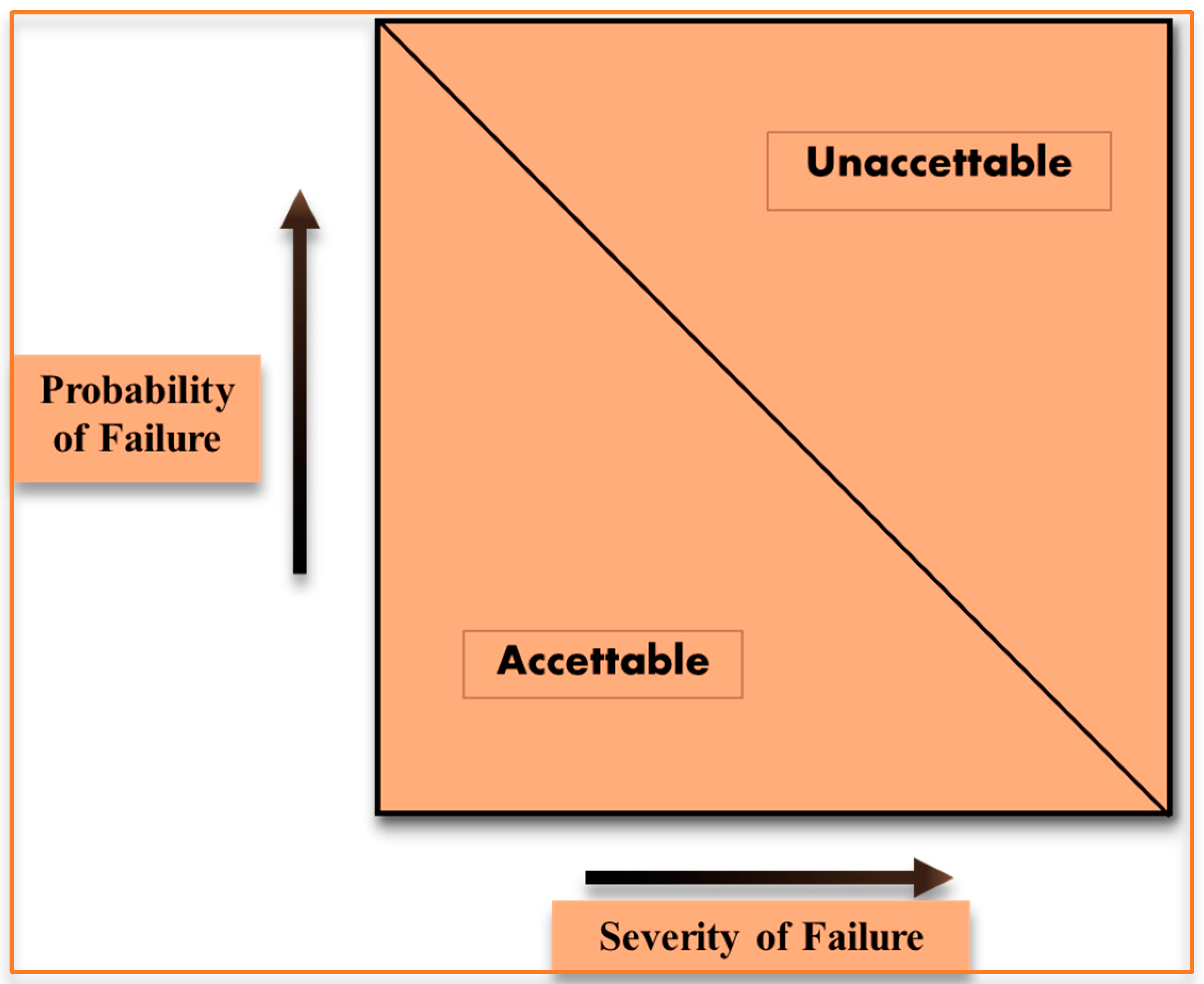
An inverse relationship exists between the average probability per flight hour and the severity of failure condition effects, as shown in
Figure 7. Catastrophic events shall be extremely improbable and shall not derive from a single failure [
24]. An approximate probability value for the term “extremely improbable” is 10
−9 corresponding to the average probability per flight hour for catastrophic failures. On the contrary, failure conditions that have less severe effects could be relatively more likely to occur and may have an upper average probability of 10
−7 (hazardous) and 10
−5 (major) per flight hour.
3.2. Morphing Winglet FHA
A safety-driven design of an adaptive winglet requires an accurate examination of the potential hazards associated with its faults.
Table 2 shows the potential system failures resulting from the FHA.
A more detailed description of the morphing winglet (MWL) FHA is given in
Table 3.
The “Actuator runaway” results in free-floating or excessive backlash for the actuator. This event may occur when either the actuator is mechanically detached from the surface or it has lost its functionality or moves in an incorrect position.
The first row of
Table 3 deals with a failure scenario developed in terms of FHA and is verified in the integrated safety aeroelastic analysis (described in the following
Section 5). All other rows, instead, regard failure scenarios not related to the aeroelastic behavior; for this reason, they were only mentioned.
Basically, the morphing winglet can impact load control/load alleviation aircraft function. The failure scenario investigated is the uncontrolled dynamic motion of the left OR right morphing winglet.
For each side, the “main actors” of the latter event identified are:
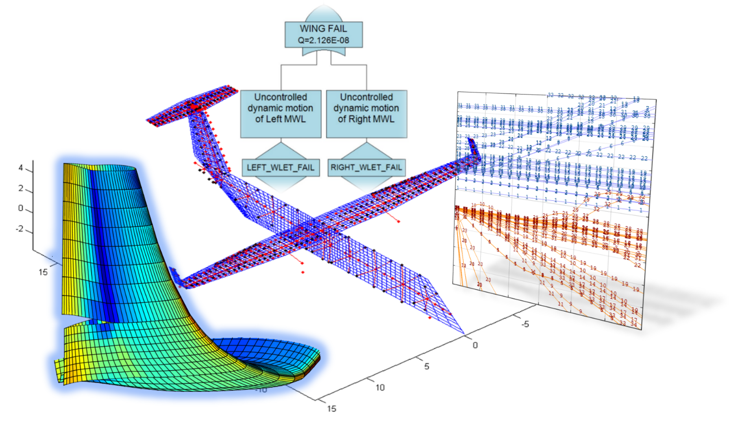
Figure 8 shows the fault tree developed only for the kinematic rupture of the upper tabs, identifying the lower tabs one as “undeveloped event” with the same failure rate. The further explosion of the gates involved occurs by
OR logic, considering the potential loss of the actuator connection, the rupture of three hinges along the first hinge line and the rupture of three hinges/links of the morphing kinematics along the second hinge line.
Moreover, for the sake of completeness, the destruction of the wing was considered as the top event of a new fault tree analysis (
Figure 9) aiming to verify its compliance with the catastrophic target (Failure probability < 10
−9).
In
Figure 9, the same failure rate was assigned to both the uncontrolled dynamic motion of right and left events, linked each other by an OR logic gate. The top event results with a failure rate of the order of 10
−8: this outcome reveals a light incompliance with respect to the CAT target (10
−9), to overcome which the use of proper damping devices on actuators or between consecutive tabs is highly suggested.
3.3. Aeroelastic Impact of the Morphing Winglet on FHA
The failures of the morphing winglet subsystems already described in the previous sections in terms of fault tree analyses may have a detrimental impact in terms of aircraft aeroelastic stability. For that purpose, the following conditions have been identified (
Table 4), as basis for the advanced aeroelastic simulations. For each morphing tab under nominal operative condition, the first hinge line stiffness equals to 1500 Nm/rad, corresponding to the lumped torsional stiffness of the related actuation chain.
All the failure scenarios are schematically shown in
Figure 10.
It is expected that the structural failure of the link (upper/lower) would give catastrophic effects in terms of flutter behavior, since it would avoid the load alleviation function of the morphing winglet at high speed being activated. All these cases will be widely aeroelastically analyzed and discussed in the next paragraphs.
4. Structural Model
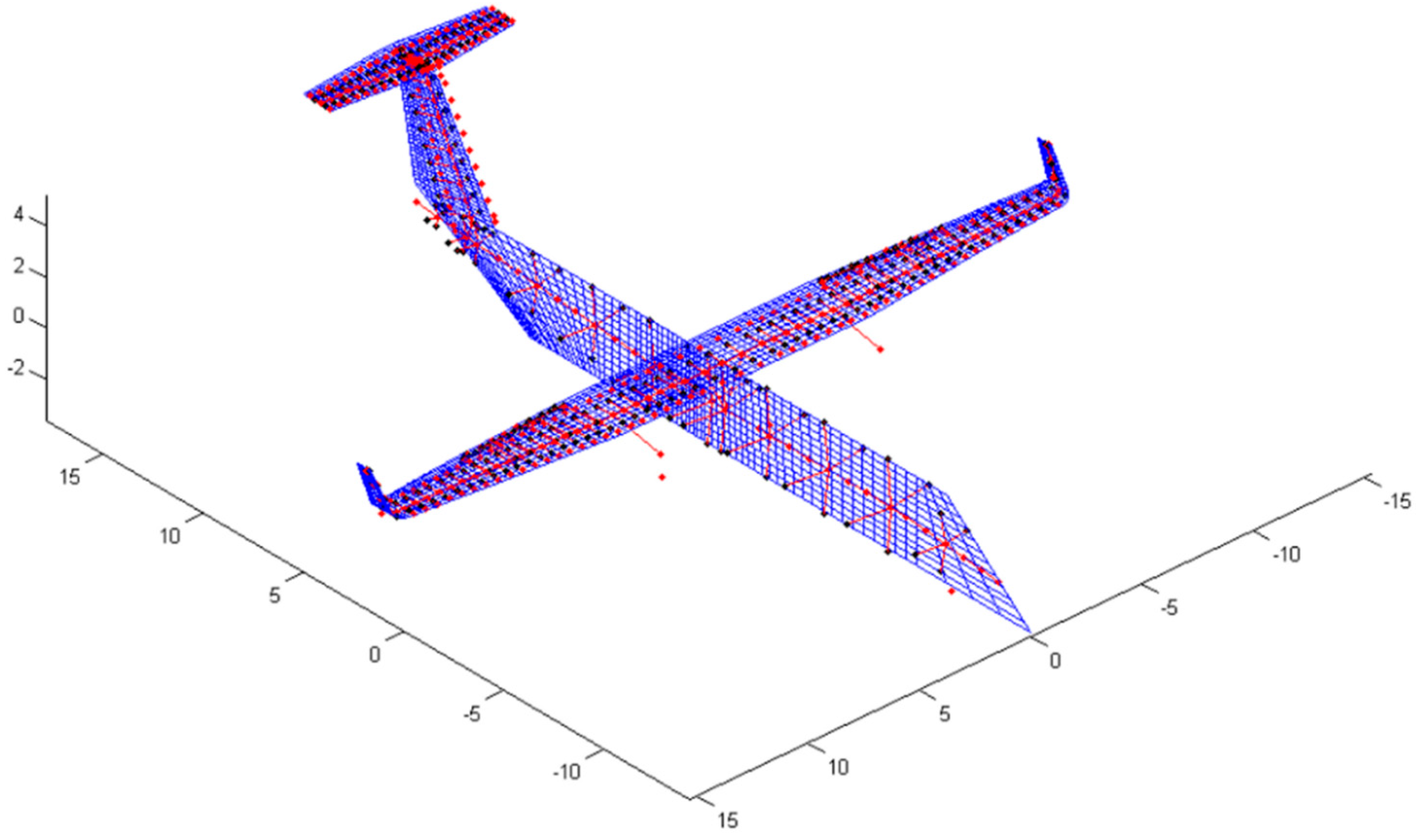
For the purpose of performing quick trade-off analyses on the whole aircraft equipped with the adaptive winglets, the structural model of the reference aircraft, already presented in [
21], was combined with a stick-beam model of the adaptive winglet. Starting from a complete finite element model of the winglet, shown in
Figure 11, the equivalent stick-beam model was generated by firstly computing the position of the elastic axis and then by assuming a reasonable stiffness distribution along the winglet span.
Such a distribution was determined by iteratively performing several Nastran runs by constraining the first node of the (assessed) elastic/hinge axis and by imposing a known load value at the tip (last node of the elastic/hinge axis). Then, a torque
Mx, about the elastic/hinge axis, yielded rotations of master nodes around
x-axis (elastic/hinge axis). The derivative of these rotations with respect to
x coordinate was evaluated to determine the torsional stiffness
GJ(
x). A Bending moment, about
y (and
z) axis, yielded rotations of master nodes around y (and z)-axis. The derivative of these rotations with respect to
y (and
z) coordinate was evaluated to determine the bending stiffness
EI(
x). A Normal force, aligned to the elastic axis, produced displacements of master nodes along
x-axis (elastic/hinge axis). The derivative of these displacements with respect to x coordinate was evaluated to determine the axial stiffness
EA(
x). The relative equations are summarized in
Table 5.
where:
x is the generic coordinate along the x-axis;
GJ(x) is the torsional stiffness distribution;
EImin(x) is the vertical bending stiffness distribution (stiffness to bending across XY plane, Y being in the winglet middle plane, normal to the elastic axis and rearward oriented);
EImax(x) is the lateral (fore & aft) bending stiffness distribution (stiffness to bending across XZ plane, z-axis oriented so that XYZ is a counterclockwise coordinate system);
EA(x) is the distribution of the stiffness exhibited with respect to forces acting along the elastic axis (normal-to-sections solicitations);
Mx is an arbitrary torque moment acting around the elastic axis (x-axis) at its free-end and Rx(x) is the rotation around the x-axis of the cross-section at span-wise location x;
My is an arbitrary torque moment acting around the y-axis at its free-end and Ry(x) is the rotation around the x-axis of the cross-section at span-wise location x;
Mz is an arbitrary bending moment acting around z-axis at elastic axis free-end and Rz(x) is the rotation around the z-axis of the cross-section at span-wise location x;
Nx is an arbitrary force acting along the elastic axis (x-axis) at its free-end and Tx(x) is the displacement along the x-axis of the cross-section at span-wise location x.
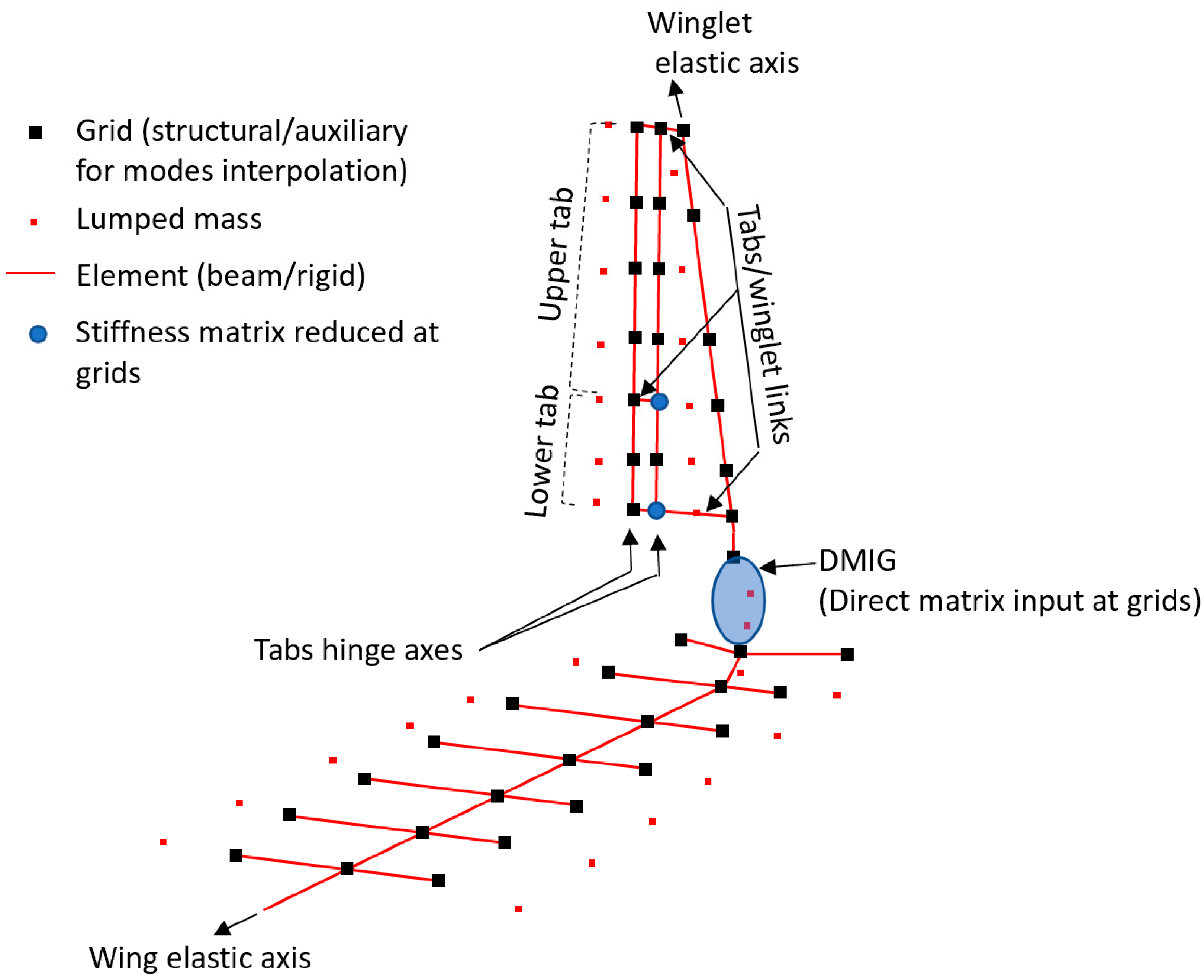
Moreover, the winglet tabs actuators were modelled by means of grounded spring elements connected to the end grid of each movable table.
Dedicated direct input matrices condensed at grids (DMIG) were then derived to properly account stiffness and inertial properties of the interface region between the described morphing winglet and the wing. Auxiliary (not structural) grids were used to assure high-quality interpolation of modal displacements along the aerodynamic lattice; auxiliary grids were linked to structural grids by means of RBE elements.
Dynamic Model
The evaluation of the inertial properties of the winglet tabs was obtained through a system of lumped masses, each of them having weight equal to the one of the intersection structural area between the tab blocks and the bays. Such masses were thus condensed at the gravity center of each tab, and then rigidly linked to the closest structural grid of the beam-equivalent model of the pertaining item. This is possible thanks to the hypothesis of considering all the lifting surfaces chordwise deformations negligible with respect to the spanwise ones. In this way, the inertial effect of each trunk can be represented through a node located at the gravity center, with its weight and barycentric inertial moments.
The dynamic model of the morphing winglet is depicted in
Figure 12.
5. Aeroelastic Analyses in Failure Conditions
The aeroelastic stability equation was solved in frequency domain and by referring to well-consolidated methodologies (PK-English method) for the evaluation of critical speeds under the following general assumptions:
association of the theoretical elastic modes up to 30 Hz; natural frequencies and shapes evaluated by means of Lanczos method applied to the dynamic model described in the manuscript;
modal damping conservatively set to 1.5% for all the elastic modes;
all moveable surfaces locked;
sea-level flight altitude;
flight speed range: [0:1.15 V Dive] as for certification requirements.
Several flutter analyses were carried out by considering the failure scenarios detailed in
Table 4.
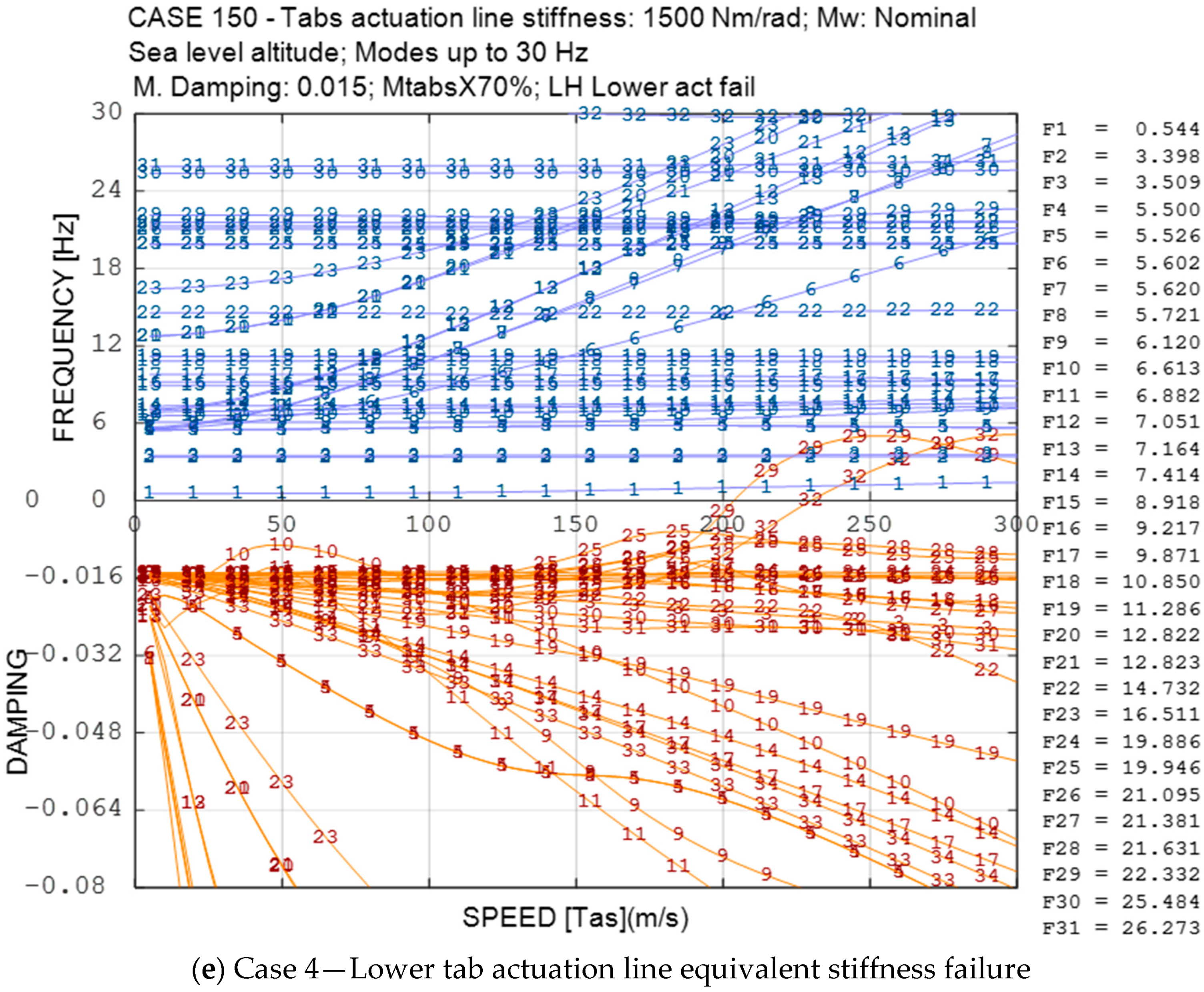
Figure 13 shows the resulting trends of modes frequencies and damping versus speed, evaluated for the four failure cases shown in
Figure 10.
The results of the flutter analyses can be summarized as follows in
Table 6.
It follows that the isolated link rupture (Cases 1 and 2) appears more critical than the isolated actuator loss (Cases 3 and 4) whereas the upper link rupture (Case 1) is more critical than the lower one (Case 2). The only aeroelastically safe events were classified in Cases 3 and 4. Additionally, in order to increase the safety margins in compliance with the FHA severity, actuators and tabs damping shall be further increased [
25].
6. Conclusions
This paper provides a safety-driven design of a morphing winglet device integrated into a 90-seat turboprop (TP90) regional transportation aircraft, in combination with aeroelastic assessments.
Experience teaches that due to the augmented degree of freedoms (DOF), morphing wings are more prone to aeroelastic instabilities than more conventional architectures integrating passive counterparts. Non-classical effects may arise in terms of flutter-instabilities due to the unconventional systems arrangement and their mutual interaction, especially in malfunctioning or failure conditions.
Fault tree analyses were performed on winglet as isolated devices to quantify the probability of failure scenarios and to verify their eventual compliance with the airworthiness requirements. Such studies drove the combined aeroelastic assessments by considering several failure cases (isolated link/actuator rupture). Gained results showed that actuator failure is more critical than link rupture, and the aeroelastic instabilities can be overcome by using proper damping devices.
Author Contributions
M.C.N.—Generation of the aeroelastic model, execution of the aeroelastic stability analyses, assessment of results. Original draft paper preparation and support to the final review; I.D.—Definition of the modelling strategies for the generation of the winglet FEM; definition of the approaches and methodologies to assess the failure scenarios of the morphing devices (FHA). Support to paper preparation, revision and editing; A.C.—Supervision of the activities related to the FHA, support to paper preparation and revision; F.A.—Generation of the winglet finite elements model and to the simulation of the actuator mechanics; R.P.—Definition of the approaches for the aeroelastic model generation (model conceptualization) and for the aeroelastic stability analyses. Individuation of the relevant flutter cases to be investigated and overall supervision of the aircraft aeroelastic assessment. Support to paper preparation, revision and editing.
Funding
Part of the research described in this paper has been carried out in the framework of AirGreen 2 Project, which gratefully received funding from the Clean Sky 2 Joint Undertaking, under the European’s Union Horizon 2020 research and innovation Program, Grant Agreement No. 807089—REG GAM 2018—H2020-IBA-CS2-GAMS-2017.
Acknowledgments
The authors would like to thank Leonardo Aircraft, for having provided the industrial guidelines and the necessary support to the research work addressed by this paper.
Conflicts of Interest
The author declares no conflict of interest.
References
- Browman, J.; Sanders, B.; Weisshaar, T. Evaluating the Impact of Morphing Technologies on Aircraft Performance. In Proceedings of the 43rd AIAA/ASME/ASCE/AHS/ASC Structures, Structural Dynamics, and Materials Conference, Denver, CO, USA, 22–25 April 2002. AIAA Paper 2002-1631. [Google Scholar]
- Concilio, A.; Dimino, I.; Lecce, L.; Pecora, R. Morphing Wings Technology for Large Commercial Aircraft and Helicopter Scenario; Butterworth-Heinemann: Oxford, UK, 2017; p. 978. ISBN 978-0-08-100964-2. [Google Scholar] [CrossRef]
- Woelcken, P.C.; Papadopoulos, M. Smart Intelligent Aircraft Structures (SARISTU); Springer International Publishing: Cham, Switzerland, 2016; ISBN 978-3-319-22413-8. [Google Scholar]
- Barbarino, S.; Bilgen, O.; Ajaj, R.M.; Friswell, M.I.; Inman, D.J. A Review of Morphing Aircraft. J. Intell. Mater. Syst. Struct. 2011, 22, 823–877. [Google Scholar] [CrossRef]
- Falcao, L.; Suleman, A.; Gomes, A. Study of an Articulated Winglet Mechanism. In Proceedings of the 54th AIAA/ASME/ASCE/AHS/ASC Structures, Structural Dynamics, and Materials Conference, Boston, MA, USA, 8–11 April 2013. [Google Scholar]
- Bendsøe, M.P.; Sigmund, O. Topology Optimization—Theory, Methods, and Applications; Springer: Heidelberg/Berlin, Germany, 2003. [Google Scholar]
- Zhao, A.; Zou, H.; Jin, H.; Wen, D. Structural design and verification of an innovative whole adaptive variable camber wing. Aerosp. Sci. Technol. 2019, 89, 11–18. [Google Scholar] [CrossRef]
- Pecora, R.; Amoroso, F.; Noviello, M.C.; Concilio, A.; Dimino, I. Aeroelastic Stability Analysis of a Large Civil Aircraft Equipped with Morphing Winglets and Adaptive Flap Tabs. In Proceedings of SPIE. 10595, Active and Passive Smart Structures and Integrated Systems XII; SPIE: Bellingham, WA, USA, March 2018. [Google Scholar]
- Arena, M.; Noviello, M.C.; Rea, F.; Amoroso, F.; Pecora, R.; Amendola, G. Modal Stability Assessment for a Morphing Aileron Subjected to Actuation System Failures: Numerical Analysis Supported by Test Evidence. In Proceedings of the 7th International Conference on Mechanical and Aerospace Engineering, (ICMAE 2016), London, UK, 18–22 July 2016; Article Number 7549580. pp. 437–442. [Google Scholar]
- Amendola, G.; Dimino, I.; Magnifico, M.; Pecora, R. Distributed Actuation Concepts for a Morphing Aileron device. Aeronaut. J. 2016, 120, 1365–1385. [Google Scholar] [CrossRef]
- Amendola, G.; Dimino, I.; Amoroso, F.; Pecora, R. Experimental Characterization of an Adaptive Aileron: Lab Tests and FE Correlation. In Proceedings SPIE 9803, Sensors and Smart Structures Technologies for Civil, Mechanical, and Aerospace Systems 2016; SPIE: Bellingham, WA, USA, 20 April 2016; 98034P. [Google Scholar] [CrossRef]
- Dimino, I.; Concilio, A.; Pecora, R. Primary Structural Components Characterization of an Adaptive Trailing Edge Device (ATED). In Proceedings of the 24th AIAA/AHS Adaptive Structures Conference, San Diego, CA, USA, 4–8 January 2016. [Google Scholar]
- Pecora, R.; Concilio, A.; Dimino, I.; Amoroso, F.; Ciminello, M. Structural Design of an Adaptive Wing Trailing Edge for Enhanced Cruise Performance. In Proceedings of the 24th AIAA/AHS Adaptive Structures Conference, San Diego, CA, USA, 4–8 January 2016. [Google Scholar]
- Pecora, R.; Amoroso, F.; Magnifico, M.; Dimino, I.; Concilio, A. KRISTINA: Kinematic Rib Based Structural System for Innovative Adaptive Trailing Edge. In Proceedings SPIE 9801, Industrial and Commercial Applications of Smart Structures Technologies 2016; SPIE: Bellingham, WA, USA, 16 April 2016; 980107. [Google Scholar] [CrossRef]
- Dimino, I.; Amendola, G.; Di Giampaolo, B.; Iannaccone, G.; Lerro, A. Preliminary design of an actuation system for a morphing winglet. In Proceedings of the 8th International Conference on Mechanical and Aerospace Engineering (ICMAE), Prague, Czech Republic, 22–25 July 2017; pp. 416–422. [Google Scholar]
- Dimino, I.; Ameduri, S.; Concilio, A. Preliminary failure analysis and structural design of a morphing winglet for green regional aircraft. In Proceedings of the ASME 2018 Conference on Smart Materials, Adaptive Structures and Intelligent Systems (SMASIS2018), San Antonio, TX, USA, 10–12 September 2018. [Google Scholar]
- Amendola, G.; Dimino, I.; Concilio, A.; Amoroso, F.; Pecora, R. Preliminary design of an adaptive aileron for the next generation regional aircraft. J. Theor. Appl. Mech. 2017, 55, 307–316. [Google Scholar] [CrossRef]
- Dimino, I.; Gallorini, F.; Palmieri, M.; Pispola, G. Electromechanical Actuation for Morphing Winglets. Actuators 2019, 8, 42. [Google Scholar] [CrossRef]
- Amendola, G.; Dimino, I.; Concilio, A.; Andreutti, G.; Pecora, R.; Cascio, M.L. Preliminary design process for an adaptive winglet. Int. J. Mech. Eng. Robot. Res. 2018, 7, 83–92. [Google Scholar] [CrossRef]
- Lo Cascio, M. Topological Optimization of an Adaptive Trailing Edge for a Morphing Winglet. Master’s Thesis, University of Palermo, Palermo, Italy, 2017. [Google Scholar]
- Noviello, M.C.; Dimino, I.; Amoroso, F.; Concilio, A.; Pecora, R. Preliminary assessment of morphing winglet and flap tabs influence on the aeroelastic stability of next generation regional aircraft. In Proceedings of the ASME 2018 Conference on Smart Materials, Adaptive Structures and Intelligent Systems (SMASIS2018), San Antonio, TX, USA, 10–12 September 2018. [Google Scholar]
- Guidelines for Development of Civil Aircraft and Systems; ARP 4754A; US SAE International: Warrendale, PA, USA, 21 December 2010.
- Guidelines and Methods for Conducting the Safety Assessment Process on Civil Airborne Systems and Equipment; ARP 4761; US SAE International: Warrendale, PA, USA, 1 December 1996.
- Certification Specifications and Acceptable Means of Compliance for Large Aeroplanes—CS-25, Amendment 11; European Aviation Safety Agency: Cologne, Germany, July 2011.
- Noviello, M.C. Aeroelastic stability assessment of a CS-25 category aircraft equipped with multi-modal wing morphing devices. Ph.D. Thesis, University of Naples “Federico II”, Naples, Italy, January 2019. [Google Scholar]
© 2019 by the authors. Licensee MDPI, Basel, Switzerland. This article is an open access article distributed under the terms and conditions of the Creative Commons Attribution (CC BY) license (http://creativecommons.org/licenses/by/4.0/).


 ,
, 


