Experimental Study of the Aerodynamic Interaction between the Forewing and Hindwing of a Beetle-Type Ornithopter


Department of Mechano-Informatics, Graduate School of Information Science and Technology, The University of Tokyo, 7-3-1 Hongo, Bunkyo-ku, Tokyo 113-8656, Japan
*
Author to whom correspondence should be addressed.
†
These authors contributed equally to this work.
Aerospace 2018, 5(3), 83; https://doi.org/10.3390/aerospace5030083
Submission received: 28 June 2018
/
Revised: 30 July 2018
/
Accepted: 6 August 2018
/
Published: 8 August 2018
(This article belongs to the Special Issue Bio-Inspired Aerospace System)
Abstract
:Beetles have attracted attention from researchers due to their unique combination of a passively flapping forewing and an actively flapping hindwing during flight. Because the wing loads of beetles are larger than the wing loads of other insects, the mechanism of beetle flight is potentially useful for modeling a small aircraft with a large weight. In this paper, we present a beetle-type ornithopter in which the wings are geometrically and kinematically modeled after an actual beetle. Furthermore, the forewing is designed to be changeable between no-wing, flapping-wing, or fixed-wing configurations. Micro-electro-mechanical systems (MEMS) differential pressure sensors were attached to both the forewing and the hindwing to evaluate the aerodynamic performance during flight. Whether the forewing is configured as a flapping wing or a fixed wing, it generated constant positive differential pressure during forward flight, whereas the differential pressure on the hindwing varied with the flapping motion during forward flight. The experimental results suggest that beetles utilize the forewing for effective vertical force enhancement.

1. Introduction
Although the hindwings of beetles are usually invaginated under rigid forewings, the hindwings extrude from under the forewings and perform a flapping motion in the air during flight [1,2]. In some species of beetles, the forewings are deployed and vibrate passively with the flapping motion of the hindwings during flight [3]. Beetles use this tandem configuration in which the forewings do not flap and the hindwings flap. The evolutionary conservation of this phenomenon suggests that the forewing not only acts as protection in the normal state but also performs aerodynamically significant work in terms of flight performance. The wing load of beetles is significantly larger than the wing loads of other flying insects [4]. Beetles efficiently utilize both the fore- and hindwings to support the larger wing load. Thus, the beetle flight mechanism using both wings is considered to be applicable to modeling a small aircraft with a wing load larger than that of an insect due to the presence of a battery or a motor.
Many studies have investigated the aerodynamics of insect flight for insects such as dragonflies and fruit flies [5,6,7,8,9,10,11,12,13,14,15]. Methods commonly employed in these studies include airflow visualization around the wing [5,6,7,8], computational fluid dynamics (CFD) [9,10,11], and artificial wings [12,13,14,15]. Similar methods have been applied to understand the aerodynamics of flight in beetles [16,17,18,19,20,21,22]. Johansson et al. focused on the interaction between the forewings and the hindwings [19]. They visualized the airflow around the flapping wings of a tethered beetle and revealed that while the lift was improved by a camber-shaped forewing, the total flight efficiency decreased. Le et al. used the results of a CFD simulation, which indicated that a beetle supports its weight by the interaction between its forewing and its hindwing [18]. Regarding other wing interactions in tandem configurations, the interaction between flapping forewings and flapping hindwings modelled after dragonflies were reported in [23,24,25]. These studies indicated that phase lag between the wings affects the aerodynamic performance based on flight speed. However, the manner in which large aerodynamic forces occur on the non-flapping forewing and the flapping hindwing in a tandem configuration during actual beetle flight remains unknown.
To evaluate the aerodynamic forces on the wing during flapping flight, we developed a measurement method using micro-electro-mechanical systems (MEMS) differential pressure sensors that can be placed on the wing surfaces of insects or insect-modeled ornithopters [26,27,28,29,30]. By attaching the MEMS sensor to a butterfly wing, we confirmed that a differential pressure of 10 Pa occurred at the center of the forewing during take-off [27]. The sensors were also attached to the forewing and hindwing of a dragonfly-type ornithopter; the findings revealed that the differential pressure of the hindwing changed according to the phase lag between the forewings and the hindwings [30]. As indicated by previous research, the MEMS differential pressure sensor has helped to quantitatively evaluate the local aerodynamic force generated on flapping wings [27,28,29,30].
In this study, we developed a beetle-type ornithopter in which the forewings can be either fixed or flapping at a small amplitude in the same phase as that of the hindwings, while the hindwings are flapping wings. The wing designs of the ornithopter were modeled after those of a beetle. Then, we measured the differential pressure between the upper and lower surfaces of the ornithopter’s wings during forward flight by attaching a MEMS differential pressure sensor to each wing surface. Because the forewings are demountable, flights with the forewing can be compared to flights without the forewing. Using the experimental results, we evaluated the aerodynamic characteristics of beetle-type flapping flight.
2. Design and Fabrication
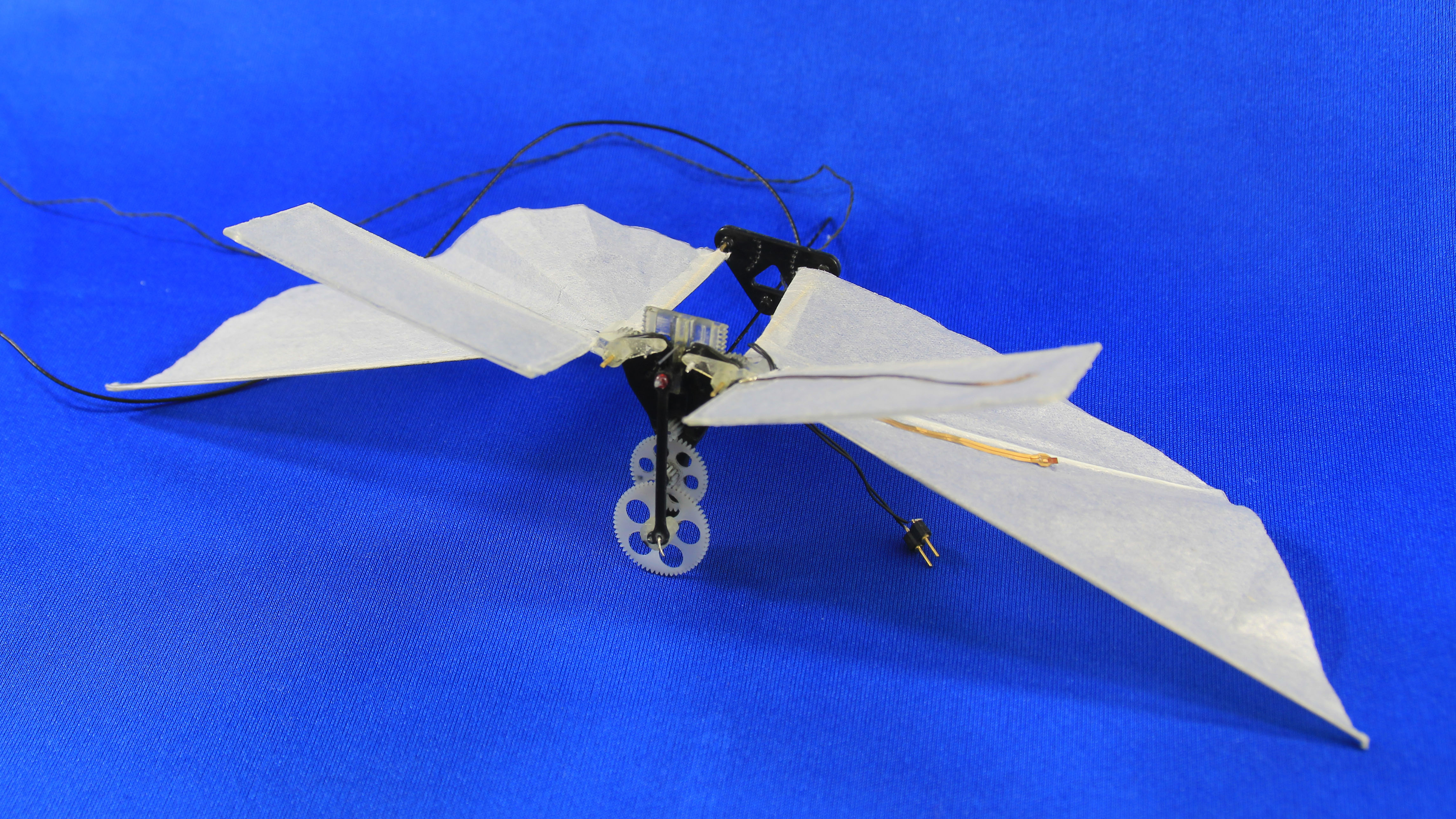
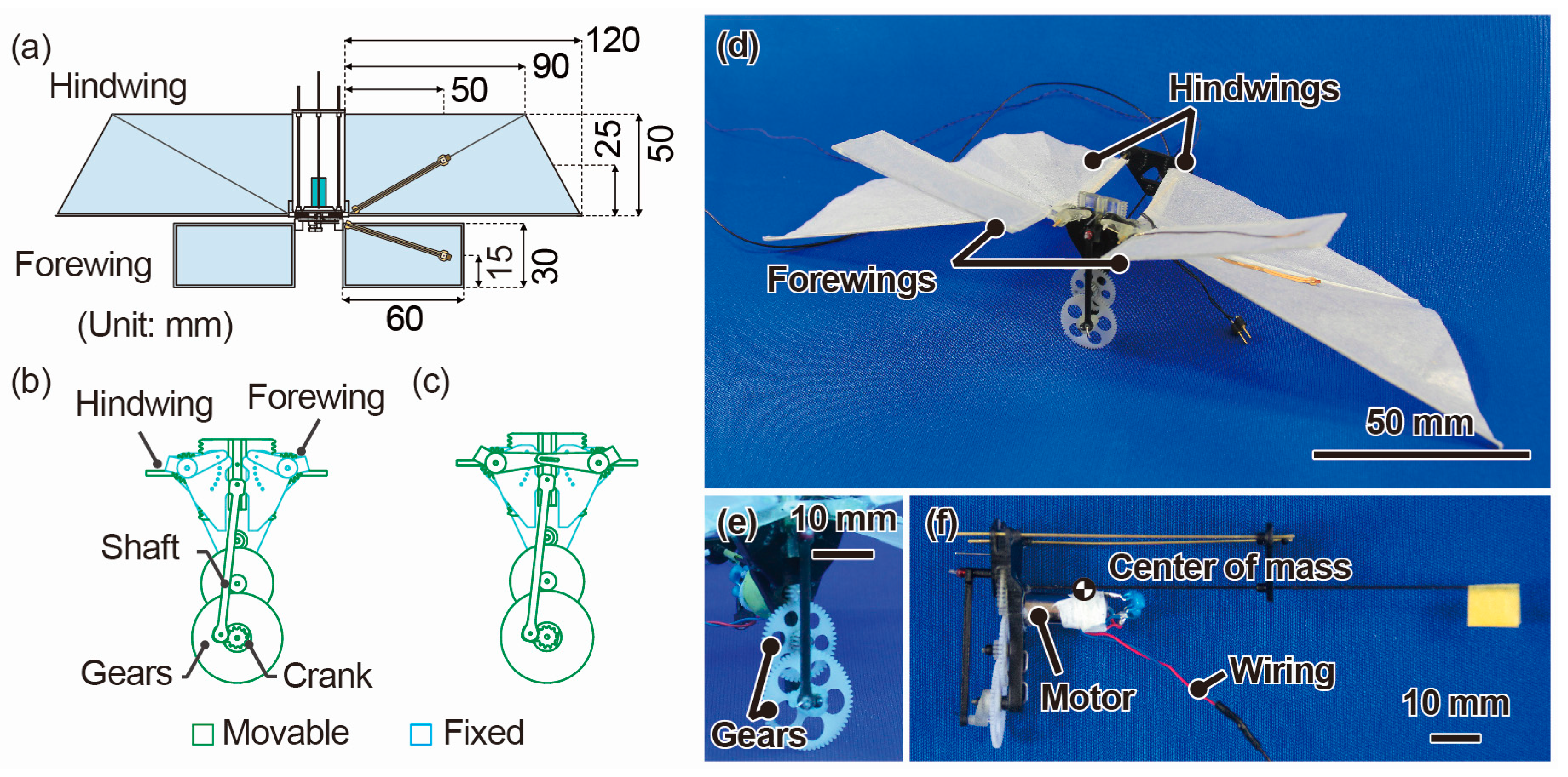
Figure 1 shows the design and images of the developed beetle-type ornithopter, which is based on our previous ornithopters [28,29,30] and driven by an electric motor with an externally located power supply. Thus, the ornithopter was composed of a long and thin body (more similar to a butterfly than a beetle). However, the geometric design of the ornithopter’s wing was modelled after that of a beetle. The wing motion was also kinematically modeled after a beetle. In this research, the forewings are demountable: they can be changed to be fixed or to flap at a small amplitude in the same phase as that of the hindwings. Table 1 and Table 2 show each design parameter for both an actual beetle and the developed ornithopter. The aspect ratios of the forewing and hindwing are designed to be similar to those of actual beetles. The total weight of the ornithopter, including cables, is approximately 14 g. The weight of a single forewing is 0.47 g, which is relatively small compared with the total weight, and the forewings are located near the center of mass of the main frame, as shown in Figure 1f. Thus, the existence of the forewing close to the center of mass had minimal influence. The wing loads of the ornithopter with and without the forewing are 10.0 N/m2 and 12.3 N/m2, respectively. The reduced frequency k at the position of the center of the hindwings is roughly calculated providing that the forward flight velocity is zero because the forward flight velocity is rather small compared to the wing-flapping velocity at the center of the hindwings. Then, the reduced frequency is defined as k = 1/(ARHind·θP-P/2) where ARHind is the aspect ratio of the hindwings. Although the flapping frequency and hindwing length are lower and longer, respectively, than those of beetles, the Reynolds number and reduced frequency are similar to those of beetles.
The sizes of the forewing and hindwing are 60 mm × 30 mm and 120 mm × 50 mm, respectively. The ratio of the wing area of the forewings to the wing area of the hindwings is approximately 4:10, which is similar to that of beetles. We designed the forewing as a flat plate composed of frames constructed with a three-dimensional (3D) printer (Stratasys, Eden Prairie, MN, USA), Objet Eden 260 V, Fullcure720) and paper with a thickness of 50 μm. The hindwing is composed of the same paper and involves frames constructed of carbon rods with a diameter of 0.5 mm and plastic corner materials with dimensions of 0.75 mm × 0.75 mm. The flapping motions of both the forewing and the hindwing are driven by converting the rotational motion of the motor using a slider-crank mechanism, as shown in Figure 1b,c [30]. The stroke plane angles of both the fore- and hindwings are 90°, which indicates that the stroke plane is perpendicular to the body axis. The amplitude of the flapping angle of the hindwing is designed to be −70° to +90°, which is similar to that of beetles. When the ornithopter is configured to have a fixed forewing, the forewing is fixed to the main body at a flapping angle of 14° (Figure 1b). In the case of a flapping forewing, the amplitude is designed to be +10° to +50° (Figure 1c), which is similar to passively-flapping motion of beetle’s forewings. We can configure the forewing to a fixed or flapping mode by changing the position of the pin attachment on the crank mechanism. In addition, the feathering motion of the hindwings is caused by passive deformation which is similar to that of beetles and similar to that reported for previous ornithopters [28,29,30]. On the other hand, no feathering motion occurs in the forewings, which is similar to beetles. The applied voltage to the motor is fixed at 4 V, corresponding to a flapping frequency of approximately 14 Hz.
The differential pressure sensors using a MEMS piezoresistive cantilever were separately attached to both the forewing and the hindwing. The design and characteristics of the differential pressure sensor were described in a previous paper [26]. Using a Cu/polyimide/Cu flexible substrate with the sensor chip, an electrical connection was made from the wing surface to the wing base, as shown in Figure 2a. The attachment positions were 50 mm longitudinally from the wing base and at the center of the chord of each wing. From the wing base, the sensor signals were connected to an external bridge and amplifier circuit using wired cables in the same manner as the motor power supply. The dimensions of the sensor chip and cantilever were 1.5 mm ×1.5 mm × 0.3 mm and 125 µm × 100 µm × 0.3 µm, respectively, as shown in Figure 2b. The sensors can measure differential pressure within a range of ±100 Pa at a resolution of approximately 1 Pa. The substrate with the sensor chip weighed approximately 5 mg—less than 5% of the wing weight. For the ornithopter configuration that included the forewing, the two sensor outputs from the forewing and hindwing were measured simultaneously. In contrast, only the single sensor output from the hindwing was measured for the ornithopter configured without the forewing. The differential pressure was defined as positive when the pressure on the upper surface was smaller than that on the lower surface.
3. Experiments
Using the developed beetle-type ornithopter with the MEMS differential pressure sensors, the differential pressure was measured during forward flight. For the flight experiments, the ornithopter was launched by hand with an initial flight velocity. At the instant of manual launch, the body angle and horizontal velocity were approximately 25° and 1–1.5 m/s, respectively. Lateral views of the flight trajectories were recorded using a high-speed camera (Photron, Tokyo, Japan, FASTCAM Mini UX) that was synchronized with the measurements of the sensor signals. The flight trajectory and wing motion were obtained from the high-speed camera images. The sensor signals and high-speed camera images were measured at 1000 Hz and 500 Hz, respectively. To confirm the repeatability of the ornithopter flight, we conducted several flight experiments for each forewing condition. The cables for the sensor signals and external power supply limited the flight distance to 1.2 m; however, the flight distance during the experiments was restricted to less than 1 m to minimize the tension on the cables.
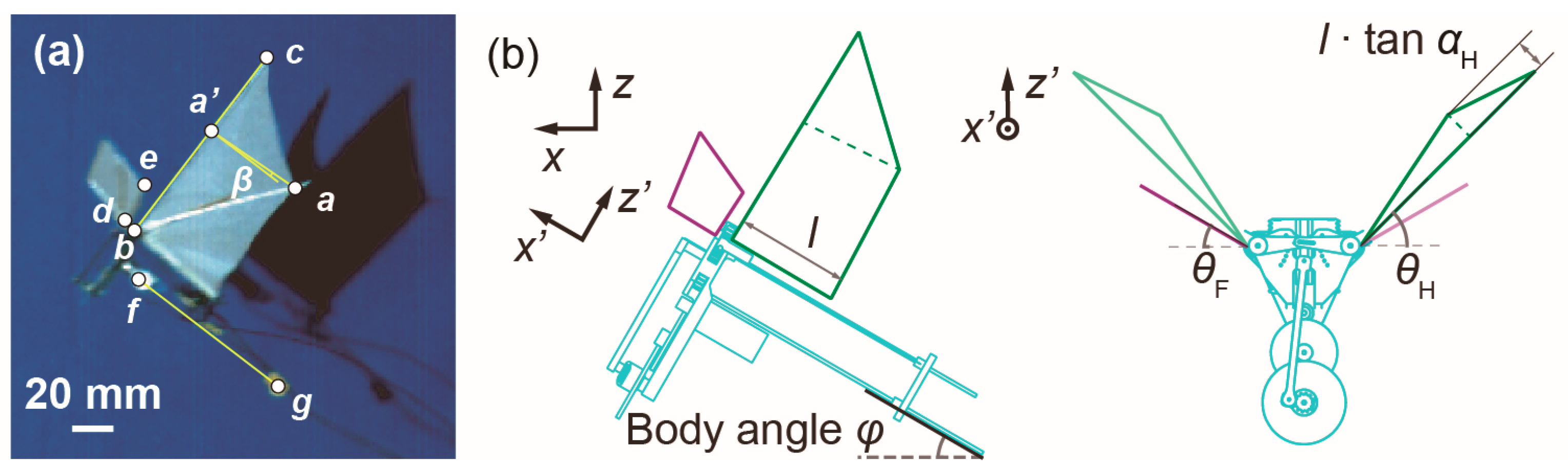
Figure 3a shows a high-speed camera image of the ornithopter during flight. We tracked the ornithopter at several points and calculated the body angle φ, the flapping angles of the forewing θF, the flapping angles of the hindwing θH, and the feathering angle of the forewing αH. Definitions of the body angle and flapping angles are shown in Figure 3b. The body angle was calculated as the angle of the line between points f and g in Figure 3a. The flapping angle of the forewing was calculated as the value of an arcsine transform of the length between points b and c in Figure 3a based on the actual wing length of the forewing. The flapping angle of the hindwing was obtained using similar calculations. The feathering angle was calculated from the relationship among the four tracking points (a, a’, f and g in Figure 3a). We defined the angle between the line from point a to point a’ and the body line β as shown in Figure 3a. Then, the feathering angle was approximately calculated as the arctangent transform of tan β per cos θH.
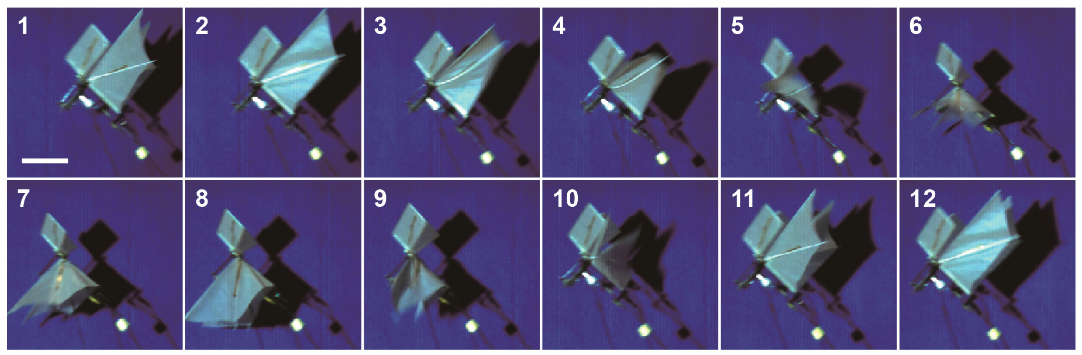
Figure 4 shows some example high-speed camera images of the flight motion of the ornithopter with flapping forewings. It was observed that the forewing vibrated synchronously with the flapping motion of the hindwing. The flight motion was similar to that of beetles.
Figure 5 shows the high-speed camera images and trajectory of the ornithopter without the forewing, with a flapping forewing, and with a fixed forewing. The high-speed camera images depict the flight every 20 ms. In addition, the trajectories are plotted to show the center of mass coordinates and the body angle of the ornithopter every 20 ms. The flapping frequency was approximately 14 Hz in each flight. To simplify the data analysis, the x-axis of the flight position plots was inverted and shown in Figure 5(a-ii,b-ii,c-ii). The test flights were performed from right to left. The variation of the body angle of the ornithopter in the test with the forewing was smaller than that in the test without the forewing. The x-axis flight velocity of the ornithopter with the forewing was maintained at approximately 1.2 m/s. When the ornithopter advanced by approximately 1 m, the vertical elevations of the ornithopter without the forewing, with the flapping forewing and with the fixed forewing decreased by −0.22 m, −0.03 m, and −0.11 m, respectively.
4. Results and Discussion
4.1. Experimental Result of Differential Pressure Measurement
The measured differential pressures, which were synchronized with the high-speed camera images, are shown in Figure 6a. Figure 6(a-i) shows only the differential pressure of the hindwing, while Figure 6(a-ii,a-iii) show the differential pressures of both the forewing and the hindwing. The differential pressure data from the sensors were smoothed using a digital bandpass filter of 0.1–100 Hz to eliminate temperature drift and electrical noise.
In all the experiments, the positive peak of the differential pressure occurred during the downstroke, whereas the negative peak occurred during the upstroke. In the case of the ornithopter with the forewing, a positive differential pressure occurred constantly in the forewing, and the average differential pressure of the hindwing was approximately 7 Pa in both the flapping forewings and fixed-forewings configurations. The peak-to-peak value of the differential pressure was approximately −40 to +85 Pa without the forewing and −50 to +60 Pa with the forewing. The differential pressure was asymmetric between the downstroke and the upstroke because the airflow velocity flow into the wing during forward flight differed due to the positive body angle [28]. The waveform of the differential pressure without the forewing was similar to that of a previous ornithopter with a single flapping wing [30]. Table 3 lists the average differential pressure values on the forewing and the peak-to-peak values on the hindwing for each condition. Each flight experiment was repeated approximately seven times to confirm the repeatability of the flight trajectories, as summarized in Table 3. Tendencies similar to those for the flight trajectory were noted for the waveforms of the measured differential pressures in each condition.
Figure 6b,c shows the body angle φ, the flapping angles of the forewing θF, the flapping angles of the hindwing θH, and the feathering angle of the forewing αH during forward flight. We calculated the flapping angle and feathering angle across three flapping cycles. In all the experiments, the flapping angle of the hindwing ranged from −60° to 70°, which was slightly smaller than the design value. In addition, feathering motion was observed on the hindwing according to the flapping movement. For the ornithopter configuration without the forewing, the body angle gradually decreased at an amplitude of approximately 20° after launch from the initial state of 25°. Conversely, for the ornithopter configured with the forewing, the amplitude was less than 10°, and the body angle was maintained at approximately 30° during flight.
4.2. Discussion
For the fixed forewing ornithopter configuration, the body angle was approximately 30°, and deviations from that body angle were small because the fixed forewings act as a damper against rotation in the pitch direction generated by the aerodynamic force from the flapping hindwings. For the ornithopter configured with flapping forewings, deviations in body angle were also small; the flapping forewings act as a damper, and the forewings flapped in the same phase as the hindwings, canceling the moments from the forewing and hindwing forces.
Differential pressure occurred in the forewing even in the fixed-forewing configuration. Thus, this differential pressure acts as a part of the aerodynamic forces that affect flight. Although accurate calculation of the total aerodynamic force generated in the wings was difficult using the measured differential pressure because it displayed non-uniform behavior over the wing surface, there is a strong correlation between the aerodynamic force and the measured differential pressure. The differential pressure was converted into the force by assuming that the measured differential pressure was uniformly applied to each wing surface. The tendencies of the force magnitudes were thought to be similar between the aerodynamic force and the converted force. We estimated the magnitude of the aerodynamic force in the x direction and the aerodynamic force in the z direction (namely, FX and FZ, respectively) from the differential pressure ΔP, the body angle φ, the feathering angle αH and the flapping angle θ of each wing. We calculated the force component F of the fixed forewings as follows:
where S is the wing area, which presented values of 3.6 × 10⁻³ m2 and 1.0 × 10⁻² m2 for the fore- and hindwings, respectively. The flapping angle θ was variable for both the flapping forewing and the hindwing, whereas it was constant in the case of the fixed forewing. In the case of the hindwing, F was split into the component forces in the x direction and z direction by multiplying it by cos (φ + αH) and −sin (φ + αH), respectively, as follows:
F = ΔP × S × |sin θ|,
FX = F × (−sin (φ + αH))
FZ = F × cos (φ + αH).
Due to a lack of feathering, F was converted into component forces in the x and z directions for the forewing as follows:
FX = F × (−sin φ)
FZ = F × cos φ.
By adding the force components of the forewing and hindwing, we evaluated the whole force for each ornithopter configuration. We employed the data from the first three flapping cycles for these calculations.
Because ornithopter tracking with the high-speed camera was performed manually, there were some errors in the calculated angles. In principle, there was a tendency for the error to increase when the flapping angle was near ±90°. However, the differential pressure was relatively small when the flapping angle was near ±90°. Thus, we considered the influence of the error of the calculated angle to be small in the overall calculation of the forces.
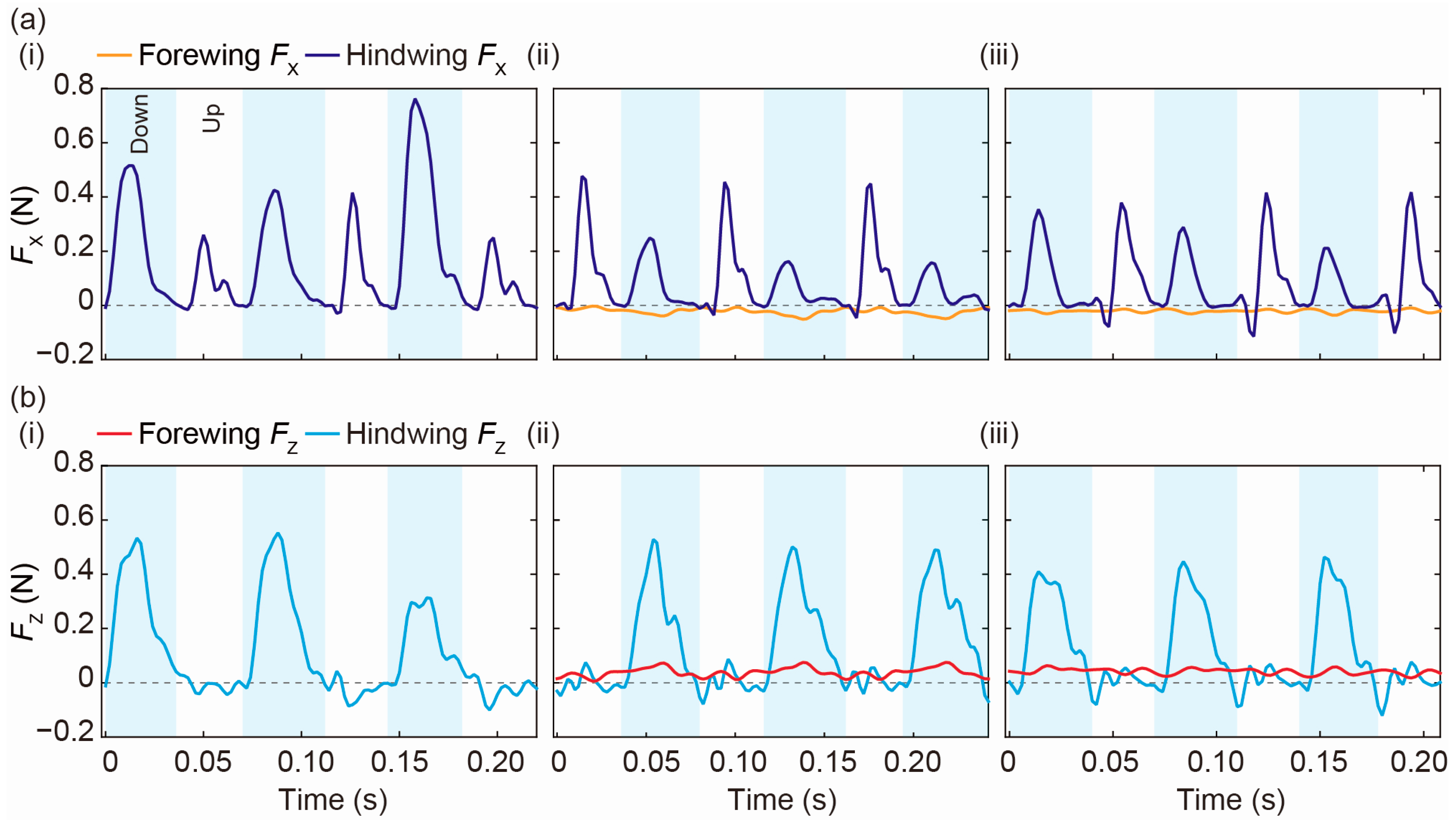
The converted forces in the x and z directions (FX and FZ, respectively) calculated based on the data in Figure 6 are shown in Figure 7. We redefined the time axis to ensure that the start of the first stroke began at zero. In all the experiments, the vertical force FZ and the propulsive force FX due to the hindwing occurred primarily during the downstroke and upstroke, respectively. The average vertical force during one flapping cycle became approximately 111 mN in the hindwing of the ornithopter without the forewing. For the flapping-forewing configuration, the average vertical forces of the forewing and hindwing were 39 mN and 125 mN, respectively. In the case of the ornithopter with the fixed forewing, these values were 42 mN and 110 mN, respectively. Focusing on the hindwing, the average vertical forces of the ornithopter with the forewing were similar to those without the forewing, whereas the differential pressure of the ornithopter with the forewing was larger than that without the forewing. Because the body angle was larger during flight, the large body angle caused improvement in the vertical force of the flapping hindwing. The total average vertical force of the ornithopter with the forewing was 1.6 times larger than that without the forewing, as shown in Figure 7, even in the case of the fixed forewing. This enhancement ratio was larger than the wing area ratio between the hindwing with the forewing and with the hindwing only, for which the value was 1.3.
In addition, the vertical components of the total force acting on the ornithopter were calculated by multiplying the mass of the ornithopter by the z directional acceleration obtained from the second-order differential of the trajectory of the center of mass, which included the gravitational acceleration [33,34,35]. The vertical components of the total force during one flapping cycle obtained from the high-speed camera images were 127 mN, 136 mN and 136 mN, in the three configurations, respectively. These values were similar to the FZ values calculated from the measured differential pressure. Conversely, the propulsive force of the forewing was a constant negative value. The propulsive force of the hindwing of the ornithopter with the forewing was smaller than that without the forewing. As a result, the x-axis velocity of the ornithopter with the forewing was slightly smaller than that without the forewing. These experimental results suggested that the forewing is utilized to support the generation of vertical force but negatively affects forward acceleration. The beetle-type ornithopter utilizes the effective vertical force enhancement from the forewing but its forward acceleration is reduced.
Several methods are available to enhance the aerodynamic vertical force of an ornithopter with flapping wings. Enlarging the wing area or adding flapping wings, such as in a dragonfly-type ornithopter, is highly effective. Another effective method is to increase the flapping frequency. However, all these methods require additional motor power, which causes an increase in body weight. In contrast, in the beetle-type ornithopter, the fixed wings are simply added ahead of the flapping wings of a single flapping wing-type ornithopter, and no additional motor power is needed. Even when we consider the additional weight of the forewings, the aerodynamic vertical force is effectively enhanced from the additional fixed forewing. Thus, the design concept of the beetle-type ornithopter can provide important design options when ornithopters need vertical force enhancement.
5. Conclusions
The aerodynamic characteristics of the forewing and hindwing of a beetle-type ornithopter were evaluated using MEMS differential pressure sensors. During forward flight, differential pressures occurred not only on the flapping hindwing but also on the forewing—regardless of whether the forewing was a fixed wing or a flapping wing. The differential pressure on the forewing was effectively transformed into a vertical force contribution of 30–40% during one flapping cycle. The use of a beetle-type forewing in flight can assist in designing ornithopters with flapping wings.
Author Contributions
All the authors contributed to the design, data analysis, and preparation of the manuscript; H.T. and K.A. fabricated the ornithopter and measured the differential pressure of the ornithopter wings during the flapping experiments; T.T. and I.S. planned and supervised the project.
Funding
This study was partly supported by Japan Society for the Promotion of Science (JSPS) KAKENHI Grant Number 25000010.
Acknowledgments
Electron beam (EB) photo mask fabrication was performed using the EB lithography apparatus at the VLSI Design and Education Center (VDEC) at the University of Tokyo.
Conflicts of Interest
The authors declare no conflicts of interest.
References
- Dudley, R. The Biomechanics of Insect Flight: Form, Function, Evolution; Princeton University Press: Princeton, NJ, USA, 2000. [Google Scholar]
- Saito, K.; Yamamoto, S.; Maruyama, M.; Okabe, Y. Asymmetric hindwing foldings in rove beetles. Proc. Natl. Acad. Sci. USA 2014, 111, 16349–16352. [Google Scholar] [CrossRef] [PubMed] [Green Version]
- Kuribayashi, S. Insects in Flight (Japanaese); Heibonsha Limited: Tokyo, Japan, 1981. [Google Scholar]
- San, H.N.; Tri, T.Q.; Seo, G.N.; Cheol, P.H. Relationship between wingbeat frequency and resonant frequency of the wing in insects. Bioinspir. Biomim. 2013, 8, 046008. [Google Scholar]
- Somps, C.; Luttges, M. Dragonfly Flight—Novel Uses of Unsteady Separated Flows. Science 1985, 228, 1326–1329. [Google Scholar] [CrossRef] [PubMed]
- Ellington, C.P.; van den Berg, C.; Willmott, A.P.; Thomas, A.L.R. Leading-edge vortices in insect flight. Nature 1996, 384, 626–630. [Google Scholar] [CrossRef]
- Srygley, R.B.; Thomas, A.L.R. Unconventional lift-generating mechanisms in free-flying butterflies. Nature 2002, 420, 660–664. [Google Scholar] [CrossRef] [PubMed]
- Thomas, A.L.R.; Taylor, G.K.; Srygley, R.B.; Nudds, R.L.; Bomphrey, R.J. Dragonfly flight: Free-flight and tethered flow visualizations reveal a diverse array of unsteady lift-generating mechanisms, controlled primarily via angle of attack. J. Exp. Biol. 2004, 207, 4299–4323. [Google Scholar] [CrossRef] [PubMed]
- Liu, H.; Ellington, C.P.; Kawachi, K.; van den Berg, C.; Willmott, A.P. A computational fluid dynamic study of hawkmoth hovering. J. Exp. Biol. 1998, 201, 461–477. [Google Scholar] [PubMed]
- Aono, H.; Liang, F.; Liu, H. Near- and far-field aerodynamics in insect hovering flight: An integrated computational study. J. Exp. Biol. 2008, 211, 239–257. [Google Scholar] [CrossRef] [PubMed]
- Young, J.; Walker, S.M.; Bomphrey, R.J.; Taylor, G.K.; Thomas, A.L.R. Details of Insect Wing Design and Deformation Enhance Aerodynamic Function and Flight Efficiency. Science 2009, 325, 1549–1552. [Google Scholar] [CrossRef] [PubMed]
- Dickinson, M.H.; Lehmann, F.O.; Sane, S.P. Wing rotation and the aerodynamic basis of insect flight. Science 1999, 284, 1954–1960. [Google Scholar] [CrossRef] [PubMed]
- Birch, J.M.; Dickinson, M.H. Spanwise flow and the attachment of the leading-edge vortex on insect wings. Nature 2001, 412, 729–733. [Google Scholar] [CrossRef] [PubMed]
- Lehmann, F.O.; Sane, S.P.; Dickinson, M. The aerodynamic effects of wing-wing interaction in flapping insect wings. J. Exp. Biol. 2005, 208, 3075–3092. [Google Scholar] [CrossRef] [PubMed] [Green Version]
- Cheng, B.; Fry, S.N.; Huang, Q.; Deng, X. Aerodynamic damping during rapid flight maneuvers in the fruit fly Drosophila. J. Exp. Biol. 2010, 213, 602–612. [Google Scholar] [CrossRef] [PubMed] [Green Version]
- Nguyen, Q.V.; Park, H.C.; Goo, N.S.; Byun, D. Characteristics of a Beetle’s Free Flight and a Flapping-Wing System that Mimics Beetle Flight. J. Bionic Eng. 2010, 7, 77–86. [Google Scholar] [CrossRef]
- Le, T.Q.; Truong, T.V.; Park, S.H.; Truong, T.Q.; Ko, J.H.; Park, H.C.; Byun, D. Improvement of the aerodynamic performance by wing flexibility and elytra–hind wing interaction of a beetle during forward flight. J. R. Soc. Interface 2013, 10, 20130312. [Google Scholar] [CrossRef] [PubMed]
- Le, T.Q.; van Truong, T.; Tran, H.T.; Park, S.H.; Ko, J.H.; Park, H.C.; Byun, D. How Could Beetle’s Elytra Support Their Own Weight during Forward Flight? J. Bionic Eng. 2014, 11, 529–540. [Google Scholar] [CrossRef]
- Johansson, L.C.; Engel, S.; Baird, E.; Dacke, M.; Muijres, F.T.; Hedenström, A. Elytra boost lift, but reduce aerodynamic efficiency in flying beetles. J. R. Soc. Interface 2012, 9, 2745–2748. [Google Scholar] [CrossRef] [PubMed] [Green Version]
- Van Truong, T.; Le, T.Q.; Byun, D.; Park, H.C.; Kim, M. Flexible Wing Kinematics of a Free-Flying Beetle (Rhinoceros Beetle Trypoxylus Dichotomus). J. Bionic Eng. 2012, 9, 177–184. [Google Scholar] [CrossRef] [Green Version]
- Van Truong, T.; Le, T.Q.; Tran, H.T.; Park, H.C.; Yoon, K.J.; Byun, D. Flow Visualization of Rhinoceros Beetle (Trypoxylus dichotomus) in Free Flight. J. Bionic Eng. 2012, 9, 304–314. [Google Scholar] [CrossRef]
- Le, T.Q.; Truong, T.V.; Tran, H.T.; Park, S.H.; Ko, J.H.; Park, H.C.; Byun, D. Two- and Three-Dimensional Simulations of Beetle Hind Wing Flapping during Free Forward Flight. J. Bionic Eng. 2013, 10, 316–328. [Google Scholar] [CrossRef]
- Maybury, W.L.; Lehmann, F.O. The Fluid Dynamics of Flight Control by Kinematic Phase Lag Variation between Two Robotic Insect Wings. J. Exp. Biol. 2004, 207, 4707–4726. [Google Scholar] [CrossRef] [PubMed]
- Hu, Z.; Deng, X.Y. Aerodynamic interaction between forewing and hindwing of a hovering dragonfly. Acta Mech. Sin. 2014, 30, 787–799. [Google Scholar] [CrossRef]
- Huang, H.; Sun, M. Dragonfly forewing-hindwing interaction at various flight speeds and wing phasing. AIAA J. 2007, 45, 508–511. [Google Scholar]
- Takahashi, H.; Dung, N.M.; Matsumoto, K.; Shimoyama, I. Differential pressure sensor using a piezoresistive cantilever. J. Micromech. Microeng. 2012, 22, 055015. [Google Scholar] [CrossRef]
- Takahashi, H.; Tanaka, H.; Matsumoto, K.; Shimoyama, I. Differential pressure distribution measurement with an MEMS sensor on a free-flying butterfly wing. Bioinspir. Biomim. 2012, 7, 036020. [Google Scholar] [CrossRef] [PubMed]
- Takahashi, H.; Aoyama, Y.; Ohsawa, K.; Tanaka, H.; Iwase, E.; Matsumoto, K.; Shimoyama, I. Differential pressure measurement using a free-flying insect-like ornithopter with an MEMS sensor. Bioinspir. Biomim. 2010, 5, 036005. [Google Scholar] [CrossRef] [PubMed]
- Takahashi, H.; Sato, K.; Matsumoto, K.; Shimoyama, I. Measuring differential pressures with multiple MEMS sensors during takeoff of an insect-like ornithopter. J. Biomech. Sci. Eng. 2014, 9, JBSE0004. [Google Scholar] [CrossRef]
- Takahashi, H.; Concordel, A.; Paik, J.; Shimoyama, I. The Effect of the Phase Angle between the Forewing and Hindwing on the Aerodynamic Performance of a Dragonfly-Type Ornithopter. Aerospace 2016, 3, 4. [Google Scholar] [CrossRef]
- Quang, L.T.; Doyoung, B.; Hoon, Y.Y.; Hwan, K.J.; Park, H.C. Experimental and numerical investigation of beetle flight. In Proceedings of the 2008 IEEE International Conference on Robotics and Biomimetics, Bangkok, Thailand, 22–25 February 2009; pp. 234–239. [Google Scholar]
- Yudhono, R.; Park, H.C.; Han, C.H. Investigation of wing interaction by using a beetle-inspired flapping system. In Proceedings of the 2012 ICME International Conference on Complex Medical Engineering (CME), Kobe, Japan, 1–4 July 2012; pp. 353–356. [Google Scholar]
- Tanaka, H.; Shimoyama, I. Forward flight of swallowtail butterfly with simple flapping motion. Bioinspir. Biomim. 2010, 5, 026003. [Google Scholar] [CrossRef] [PubMed]
- Chen, M.W.; Zhang, Y.L.; Sun, M. Wing and body motion and aerodynamic and leg forces during take-off in droneflies. J. R. Soc. Interface 2013, 10, 20130808. [Google Scholar] [CrossRef] [PubMed]
- Muijres, F.T.; Chang, S.W.; van Veen, W.G.; Spitzen, J.; Biemans, B.T.; Koehl, M.A.R.; Dudley, R. Escaping blood-fed malaria mosquitoes minimize tactile detection without compromising on take-off speed. J. Exp. Biol. 2017, 220, 3751–3762. [Google Scholar] [CrossRef] [PubMed] [Green Version]
Figure 1.
(a) Design of the beetle-type ornithopter with the micro-electro-mechanical systems (MEMS) differential pressure sensors on the forewing and hindwing; (b,c) crank mechanisms of the ornithopter with a fixed forewing and flapping forewing; (d) photograph of the fabricated ornithopter; (e) close-up view of the crank mechanism; (f) side view of the frame without forewings.

Figure 2.
Photographs of (a) the hindwing with substrate and (b) the sensor chip.
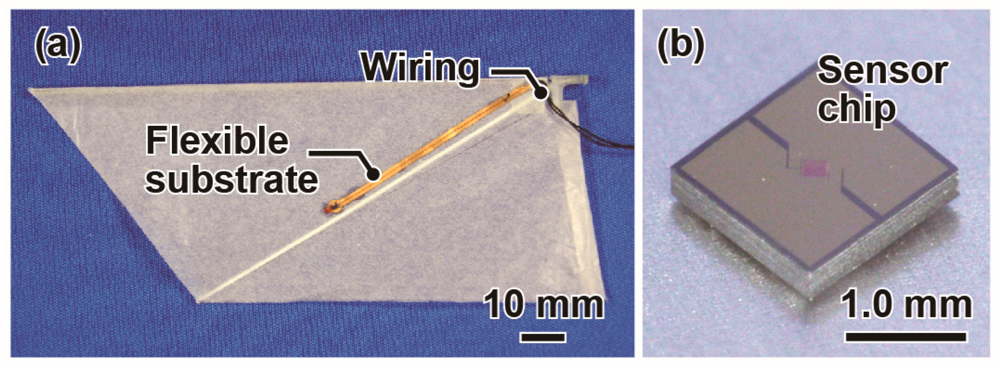
Figure 3.
(a) Tracking points of the ornithopter in the obtained high-speed camera image; (b) Definition of the body angle and flapping angles.
Figure 3.
(a) Tracking points of the ornithopter in the obtained high-speed camera image; (b) Definition of the body angle and flapping angles.

Figure 4.
The high-speed camera images of the motion during the flight of the ornithopter with flapping forewings. The interval is 8 ms. The scale bar in (1) is 100 mm. All images are provided with same scale.
Figure 4.
The high-speed camera images of the motion during the flight of the ornithopter with flapping forewings. The interval is 8 ms. The scale bar in (1) is 100 mm. All images are provided with same scale.

Figure 5.
(i) High-speed camera images and (ii) trajectory of the ornithopter (a) without forewings; (b) with flapping forewings, and (c) with fixed forewings. The high-speed camera images are shown for intervals of 20 ms; The scale bar in (a-i-1) is 100 mm. All images are provided with same scale. The trajectory is plotted with the coordinates of the center of mass and body axis every 20 ms. The trajectories with red dot are corresponding to the camera images of 1 and 12.
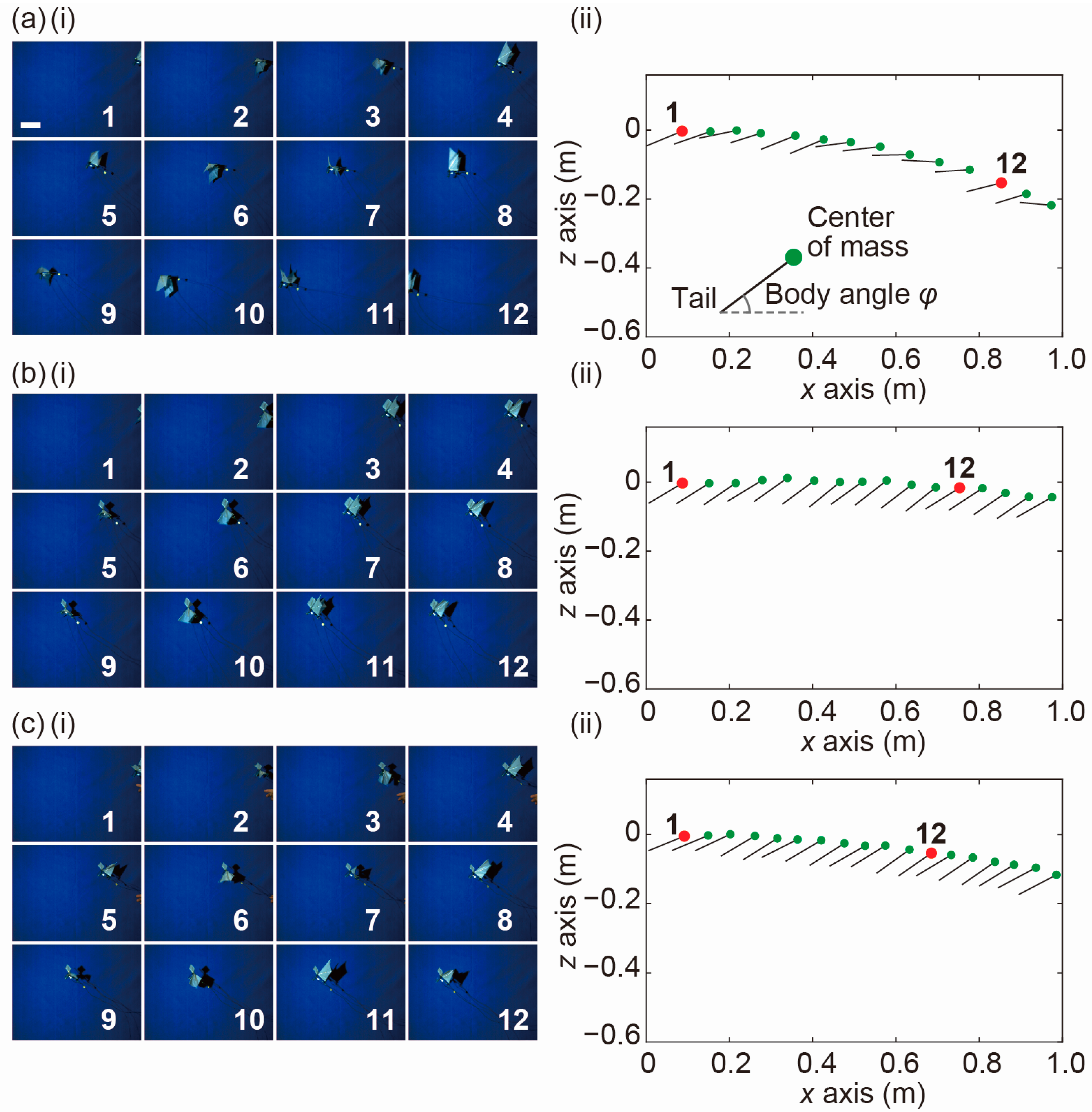
Figure 6.
(a) Differential pressures at the center of the forewing and hindwing of the ornithopter (i) without a forewing (ii) with a flapping forewing and (iii) with a fixed forewing; (b) Calculated value of the body angle φ; (c) Calculated values of the flapping angle θF, θH and feathering angle αH of the ornithopters.
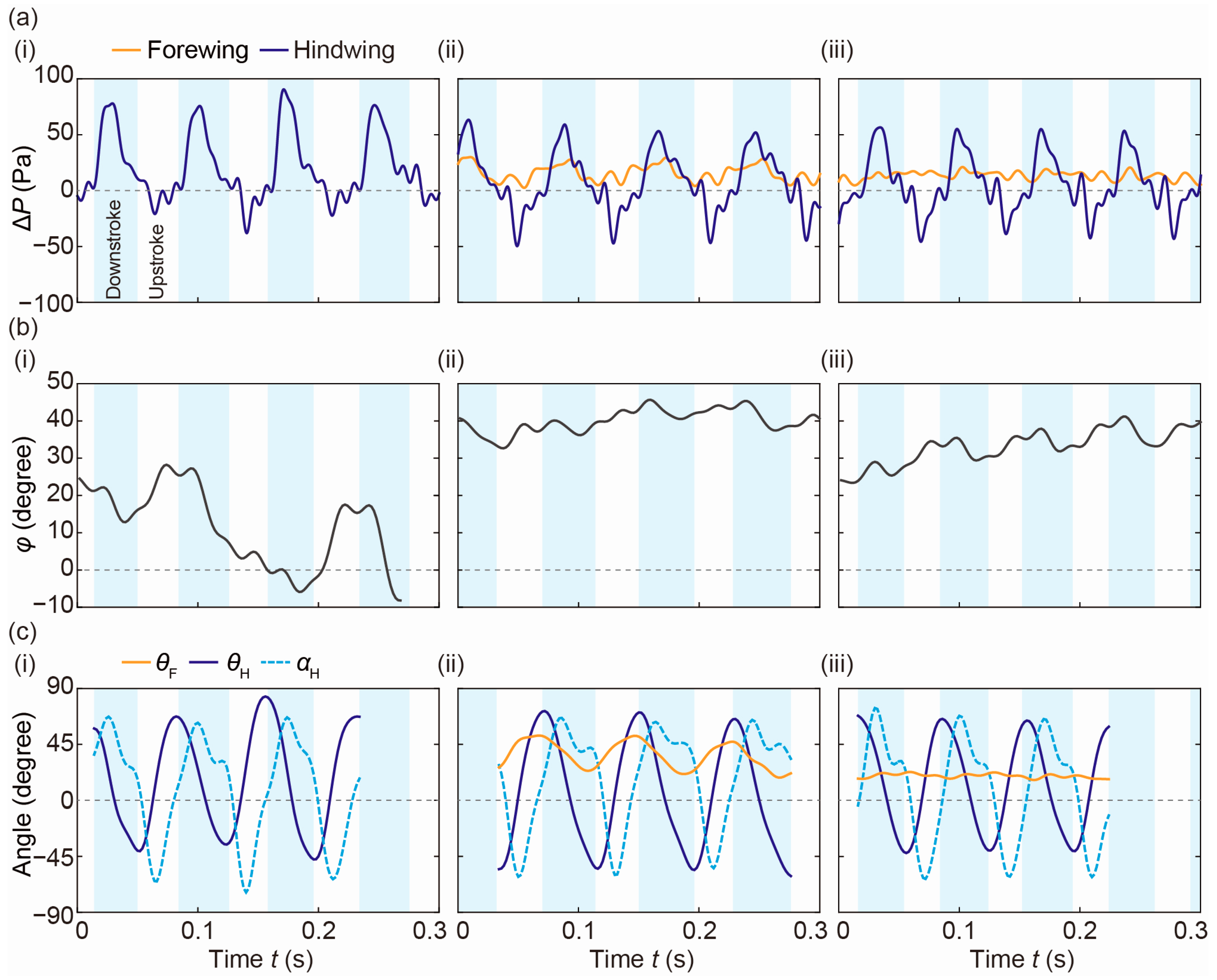
Figure 7.
(a,b) Calculated FX and FZ of the forewing and hindwing from the measured differential pressure, wing area, body angle, flapping angle and feathering angle (i) without a forewing (ii) with a flapping forewing and (iii) with a fixed forewing.
Figure 7.
(a,b) Calculated FX and FZ of the forewing and hindwing from the measured differential pressure, wing area, body angle, flapping angle and feathering angle (i) without a forewing (ii) with a flapping forewing and (iii) with a fixed forewing.

Table 1.
Characteristics of a beetle and the developed ornithopter.
| Characteristics | Unit | Beetle [16,31,32] | Ornithopter with/without Forewing |
|---|---|---|---|
| Beetle species | Allomyrina dichotoma | ||
| Hindwing length, s | mm | 56 | 120 |
| Aspect ratio of forewing | ‒ | 2.1 | 2 |
| Aspect ratio of hindwing | ‒ | 2.8 | 2.4 |
| Mass | g | 6~10 | 13.9/12.5 |
| Flapping frequency, f | Hz | 35 | 14/13 |
| Amplitude θP-P of forewing | degree | +10~+50 | +10~+50 |
| Amplitude θP-P of hindwing | degree | −70~+86 | −70~+90 |
| Wing load | N/m2 | 50 (without forewing) | 10.0/12.3 |
| Reynolds number, Re | ‒ | 3.0 × 10³ | 6.5 × 10³ |
| Reduced frequency, k | ‒ | 0.13 | 0.15 |
Table 2.
Weight composition of the ornithopter in grams.
| Ornithopter | Body frame | 6.28 |
| Forewings | 0.94 | |
| Hindwings | 0.57 | |
| Total | 7.79 | |
| Cables | Cables for motor supply | 3.60 |
| Cables for sensor signal | 2.51 | |
| Total | 6.11 |
Table 3.
Performances of the ornithopter during flight (i) without a forewing (ii) with a flapping forewing and (iii) with a fixed forewing.
Table 3.
Performances of the ornithopter during flight (i) without a forewing (ii) with a flapping forewing and (iii) with a fixed forewing.
| Characteristics | (i) | (ii) | (iii) |
|---|---|---|---|
| Forewing | none | flapping | fixed |
| θF (degree) | ‒ | +10~+50 | +14 |
| f (Hz) | 13 | 14 | 14 |
| Trial number | 7 | 8 | 7 |
| Average ΔP of forewing (Pa) | ‒ | 14.7 ± 1.9 | 12.0 ± 2.2 |
| Maximum ΔP of hindwing (Pa) | 72.8 ± 8.2 | 57.0 ± 4.6 | 51.1 ± 4.3 |
| Minimum ΔP of hindwing (Pa) | −46.4 ± 10.6 | −39.8 ± 5.0 | −41.0 ± 4.4 |
© 2018 by the authors. Licensee MDPI, Basel, Switzerland. This article is an open access article distributed under the terms and conditions of the Creative Commons Attribution (CC BY) license (http://creativecommons.org/licenses/by/4.0/).
Share and Cite
MDPI and ACS Style
Takahashi, H.; Abe, K.; Takahata, T.; Shimoyama, I. Experimental Study of the Aerodynamic Interaction between the Forewing and Hindwing of a Beetle-Type Ornithopter. Aerospace 2018, 5, 83. https://doi.org/10.3390/aerospace5030083
AMA Style
Takahashi H, Abe K, Takahata T, Shimoyama I. Experimental Study of the Aerodynamic Interaction between the Forewing and Hindwing of a Beetle-Type Ornithopter. Aerospace. 2018; 5(3):83. https://doi.org/10.3390/aerospace5030083
Chicago/Turabian StyleTakahashi, Hidetoshi, Kosuke Abe, Tomoyuki Takahata, and Isao Shimoyama. 2018. "Experimental Study of the Aerodynamic Interaction between the Forewing and Hindwing of a Beetle-Type Ornithopter" Aerospace 5, no. 3: 83. https://doi.org/10.3390/aerospace5030083
Note that from the first issue of 2016, this journal uses article numbers instead of page numbers. See further details here.