Hybrid Propulsion Systems for Remotely Piloted Aircraft Systems


School of Engineering, RMIT University, Melbourne, VIC 3000, Australia
*
Author to whom correspondence should be addressed.
Aerospace 2018, 5(2), 34; https://doi.org/10.3390/aerospace5020034
Submission received: 31 December 2017
/
Revised: 19 March 2018
/
Accepted: 20 March 2018
/
Published: 29 March 2018
(This article belongs to the Special Issue Aeroengine)
Abstract
:The development of more efficient propulsion systems for aerospace vehicles is essential to achieve key objectives. These objectives are to increase efficiency while reducing the amount of carbon-based emissions. Hybrid electric propulsion (HEP) is an ideal means to maintain the energy density of hydrocarbon-based fuels and utilize energy-efficient electric machines. A system that integrates different propulsion systems into a single system, with one being electric, is termed an HEP system. HEP systems have been studied previously and introduced into Land, Water, and Aerial Vehicles. This work presents research into the use of HEP systems in Remotely Piloted Aircraft Systems (RPAS). The systems discussed in this paper are Internal Combustion Engine (ICE)–Electric Hybrid systems, ICE–Photovoltaic (PV) Hybrid systems, and Fuel-Cell Hybrid systems. The improved performance characteristics in terms of fuel consumption and endurance are discussed.
1. Introduction
One of the ultimate goals present in the aviation industry is to operate perfectly “sustainable” aircraft to facilitate operations while reducing reliance and cost on fossil fuels. The concept of sustainability is two-fold and comprises economic sustainability and environmental sustainability. To this end, the airliner of the future is likely to be an all-electric aircraft which has the capability to be autonomously operated. These two facets (all electric and autonomous) remove two of the most significant costs in the aviation industry, fuel and flight crew [1]. This then goes towards achieving the goal of economic sustainability. Furthermore, by eliminating the need for fuel, the environmental impact from the aviation industry is also significantly reduced as the majority of emissions from aviation come directly from burning fuel. There needs to be incremental change in the evolution of aircraft in the aviation industry to develop and promote the benefits of aviation sustainability. The lack of current development is driven by (1) the industry’s conservative approach utilizing proven safe and reliable systems, and (2) minimal profit margins in the industry appear to some extent to limit required investment into revolutionary technologies. Evolutionary steps towards all electric aircraft have provided incremental means to develop a stream of alternative propulsion technologies. This is clearly seen in the automotive industry. Hybridization of automobiles has made way for technology development and acceptance of hybrid vehicles. One may expect that hybrid-propulsion systems for aerospace application will develop in the same manner and become an essential entity in the aviation industry.
The advent of the unmanned aviation industry has inadvertently helped the evolution of manned aviation by providing small scale but practical test beds for the iteration of aerospace technologies. The associated cost of the design and development life cycle means that unmanned aircraft can readily make use of novel and innovative technologies. The rate of development and application into unmanned systems results in more innovation at shorter time scales. This of course further drives and grows the unmanned aviation sector. The rapid growth of unmanned aviation is essential to support the growth and expansion of the larger-scale commercial market. Currently, the market value of the unmanned aircraft market (in 2016) is estimated at $8.5 billion with projections of exponential growth (at 7.6% per annum) to $12 billion by 2021 [2]. While unmanned aircraft in the past have commonly been associated with negative press with various news outlets reporting on predator drones launching hellfire missiles [3], it is becoming increasingly common to think of the almost ubiquitous quadrotor aircraft and their many developing applications. These applications include mail, package, and pizza delivery [3], as well as the ever-expanding photography and videography sectors. There are also applications that require unmanned aircraft to achieve long endurance times and thus are specialty products that require specific expertise to operate legally [4]. Another identified growth sector is mining and agricultural survey applications. These two industries can involve the monitoring of exceptionally large areas, and hence any aircraft utilized needs to be capable of flying for many hours. When factoring in payload requirements (sensors for the surveying), the current energy density of batteries means electric multi-rotor aircraft have limited usefulness in these long-endurance missions. The increase in range and endurance could lie in the hybridization of the electric and internal combustion (IC) engine system to provide means to progress the technology and introduce it to the larger aviation industry.
The aim of this work is to review the general propulsion methods available to unmanned or remotely piloted aircraft systems (RPAS) and to present the current efforts into increasing the endurance of electric aircraft with the use of hybrid configurations. The hybrid configurations investigated and discussed in this work include the internal combustion engine (ICE) and conventional electric hybrid, the ICE and photovoltaic (PV) hybrid, and the fuel-cell hybrid. To support and understand of each of these, the constituent propulsion systems are also described. The objective of this work is to present the associated improvements in performance characteristics in terms of fuel consumption and endurance of hybrid RPAS.
2. The Existing Propulsion Systems
2.1. Battery Powered
Electric propulsion is a popular system for small and micro RPAS [5,6]. Electric propulsion is known to have a favorable electrical and mechanical efficiency while being reliable due to the simple mechanics and reduced moving parts compared to IC engines [7,8,9,10]. These systems are further divided into active and passive systems, which depend on the type of bus connection between the electric machine and the battery [9]. This is very similar to all other kinds of electric vehicles and has the following components [5].
- propeller,
- electric motor,
- energy source,
- optional gear box,
- electric power converter,
- plugs,
- connectors, and
- optional cooling system.
However, in an all-electric vehicle, the propulsion systems account for as much as 60% of vehicle density [11], with the battery pack contributing the most [12]. This is primarily due to low energy densities of the batteries, and is the limiting factor in vehicle endurance. Research in battery technology has been essential in improving battery energy density for various applications [13,14,15]. It has been reported that the calculated overall efficiency of a full battery-powered aircraft can be 73% when considering the individual efficiencies of each component (battery (100%), controller (98%), electric motor (95%), gear box (98%), and propeller (80%)) [12]. There are multiple research efforts promising better battery technologies, including: Lithium-Air (Li-O2), Lithium-Sulphate (Li-S), Zinc-Air (Zn-O), Aluminium-Air (Al-Air), Magnesium Ions, and Graphene [16]. Although the improvement of the efficiency of system components results in a more efficient propulsion design, energy density and battery technology remains the crucial element in the success of electric aircraft. These battery technologies will be used in the first instance on unmanned aircraft before any certification onto manned aircraft.
Table 1 shows the current battery specific energy density, as well as the predicted increases for the future, and the theoretical maximum achievable. Also, since the specific energy is the energy per kilogram, Table 1 is indicative of the potential to reduce the overall weight and improve the performance of the RPAS. At present, most RPAS use Li-Ion batteries because they are a proven, reliable, and available battery technology [17,18].
2.2. Fuel-Cell Powered
A fuel cell is an electrochemical cell that converts chemical energy into electrical energy through an electrochemical reaction and is classified according to the kind of electrolyte it utilizes. These include [23]:
- Polymer Electrolyte Membrane fuel cell or Proton Exchange Fuel cell (PEM),
- Direct Methanol Fuel Cells (DMFC),
- Alkaline fuel cells,
- Phosphoric acid fuel cells,
- Molten Carbonate fuel cells, and
- Solid Oxide Fuel Cell (SOFC).
The main competitors for fuel cells utilized within the aviation industry are PEM, SOFC, and DMFC.
2.2.1. Proton Exchange Fuel Cell
Proton exchange fuel-cells are the most commonly used fuel cell for aerial systems [24]. They directly produce direct current (DC) electric current, operate at low temperatures, and water is the only emission (when utilizing hydrogen) [25,26]. These fuel-cells are light-weight, have comparatively higher energy density than SOFC and DMFC, and they can respond to high load changes; as such, these fuel-cells make the most favorite choice for RPASs [23,24]. However, there is still a drawback with the PEM fuel-cell when exposed to fast load changes, which reduces the life span of the already expensive fuel-cell membrane [27]. The efficiency of a typical PEM ranges between 40 and 60% [23,28,29], and the power output ranges between 100 watts and several kilowatts. The overall chemical reaction of the PEM is given as:
Anode: H2 → 2H+ + 2e−,
Cathode: ½O2 + 2H+ + 2e− → H2O,
Overall reaction: H2 + ½O2 → H2O.
2.2.2. Solid Oxide Fuel Cell
The SOFC is also referred to as a high-temperature fuel cell, since it operates between temperatures ranging from 600 to 1000 degrees Celsius [23]. This allows for potential for use in cogeneration or combined cycle applications where heat exchange is used to further improve efficiency [30]. This high temperature tends to give the flexibility of using a much denser propane fuel and gives advantage over the fuel storage space when compared to the PEM, where the less-dense hydrogen needs a heavier storage area [24]. This is a significant advantage in aircraft and aviation in general where weight is a critical factor. The efficiency of SOFCs ranges between 25 and 50% [23]. The overall chemical reaction of the SOFC is given as:
Anode: H2 + O−2 → H2O + 2e−
Cathode: ½O2 + 2e− → O−2
Overall Reaction: H2 + ½O2 → H2O.
CO and hydrocarbons, such as CH4, can also be used as fuels in an SOFC. At the high temperatures within the cell, this gives:
or in the case of natural gas:
CO + H2O → H2 + CO2,
CH4 + H2O → 3H2 + CO.
The reduction reaction occurs at the cathode (air electrode) at 1000 degrees Celsius, while fuel oxidation occurs at the anode. The anode should be porous to conduct fuel and transport the products of fuel oxidation away from the electrolyte and fuel-electrode interfaces [23,28]. The SOFC is the second most commonly utilized fuel cell behind the PEM in aerospace applications.
2.2.3. Direct Methanol Fuel Cell
The DMFC is similar to the PEM, operates at low temperature between 20 and 90 degrees Celsius, and uses methanol as a fuel. This fuel cell has less power density than the SOFC and PEM; however, the advantage of the system is the use of a denser methanol fuel that is liquid in contrast to the gas state of the hydrogen and propane, which require bulkier gas storage systems [24]. In general, liquid fuel systems are simpler to use in aerospace vehicles as storage conforms to the aircraft structure and is not geometry-dependent. The overall chemical reaction of the DMFC is given as:
Anode: CH3OH + H2O → CO2 + 6H+ + 6e−,
Cathode: 3/2O2 + 6e− + 12H+ → 3H2O.
Overall Equation: CH3OH + 3/2O2 → 2H2O + CO2
The major disadvantage of the DMFC systems is that the efficiency is 20–30% [23]. Also, as indicated in Equation (9), CO2 is also produced as an emission byproduct.
2.2.4. Fuel-Cell Powered RPAS and Endurance
Figure 1 shows the increase in RPAS fuel-cell “efficiency” relative to endurance for a 10-year period between 2003 and 2013. The first fuel-cell powered Unmanned Aerial System UAS was flown in 2003. Over the decade, advances of various technologies have increased the overall endurance from the 15 min (2003) to 48 h [24]. This represents a significant increase in the endurance capability of RPAS systems. A mission endurance of 48 h is sufficient for most RPAS applications, excluding those that require persistent on loitering mission scenarios. All of the given RPAS use PEM fuel-cell technology, where the highest endurance RPAS use a fuel cell with liquid hydrogen as fuel [31].
2.3. Photovoltaic-Powered
Some long-endurance aircraft utilize photovoltaic cells which convert solar energy into electrical energy. The cells are made into solar panels and can be integrated into the wings of an aircraft. A solar cell system usually comprises a form of energy storage, such as batteries, to supply extra energy to the propulsion system or to store excess harvested energy away until it is operationally needed. Solar panels use a photovoltaic process to convert radiative solar energy to electrical energy through Photovoltaic Cells (PVs) [32,33]. These PV and battery systems are well-suited for High Altitude Long Endurance (HALE), and the system needs a larger wing surface area to accommodate the PV panels. Li-ion and Lithium polymer batteries are the most common batteries that are used in conjunction with PV. Endurance is reliant on the availability of solar activity (sun light) [34]. Solar panels for aerospace application are typically expensive due to geometry and weight requirements [35]. Improving the efficiency of individual components can improve the overall efficiency. For example, high Power Conversion Efficiency (PCE), weight, flexibility, mechanical resilience, and operational stability can all improve the overall efficiency of a PV system [36]. There are promising materials that will improve these conditions; these include advanced silicon [37], ultrathin kesterites [38], organic and inorganic semiconductors [36,39], organo-lead halide perovskites [40,41], and improved PCE [42]. There is further research investigating the implementation of PV panels with high power-to-weight ratio solar cells [36]. Such panels inhibit flexible material properties, allowing for a flexible wing design which would absorb turbulence and reduce aircraft perturbation. Furthermore, it would allow shape conformity to maximize the PV-occupied wetted area and solar power yield.
Figure 2 shows the increase in endurance of solar-powered aerial vehicles over almost 40 years, starting with research from 1974 through to 2010 [43,44]. Advances in PV technology and materials and battery technology contribute significantly to this [44]. The trend suggests that solar-based propulsion endurance has increased over the years by many orders of magnitude. Specifically, in 1974 the endurance was just 20 min [45]. In 2010, the endurance was recorded as 336 h, 22 min, and 8 s. So, from 1974 to 2010 there has been an increase by a factor of 1009, that is, 3 orders of magnitude in less than 40 years. The goal of persistent loitering with solar-powered aircraft is clearly achievable. However, the limitations are in terms of available payload for useful operations.
2.4. Internal Combustion Engine
Internal combustion engines represent the traditional form of propulsion for aviation. For aviation, it currently stands as the most common form of propulsion system. Piston engine technologies are more popular for general aviation aircraft, including larger long endurance unmanned aerial vehicles (UAVs). Gas turbine engines are another form of ICE engine with widespread use in commercial aviation. Both of these engine types can be divided into further sub-types.
2.4.1. Piston Engine
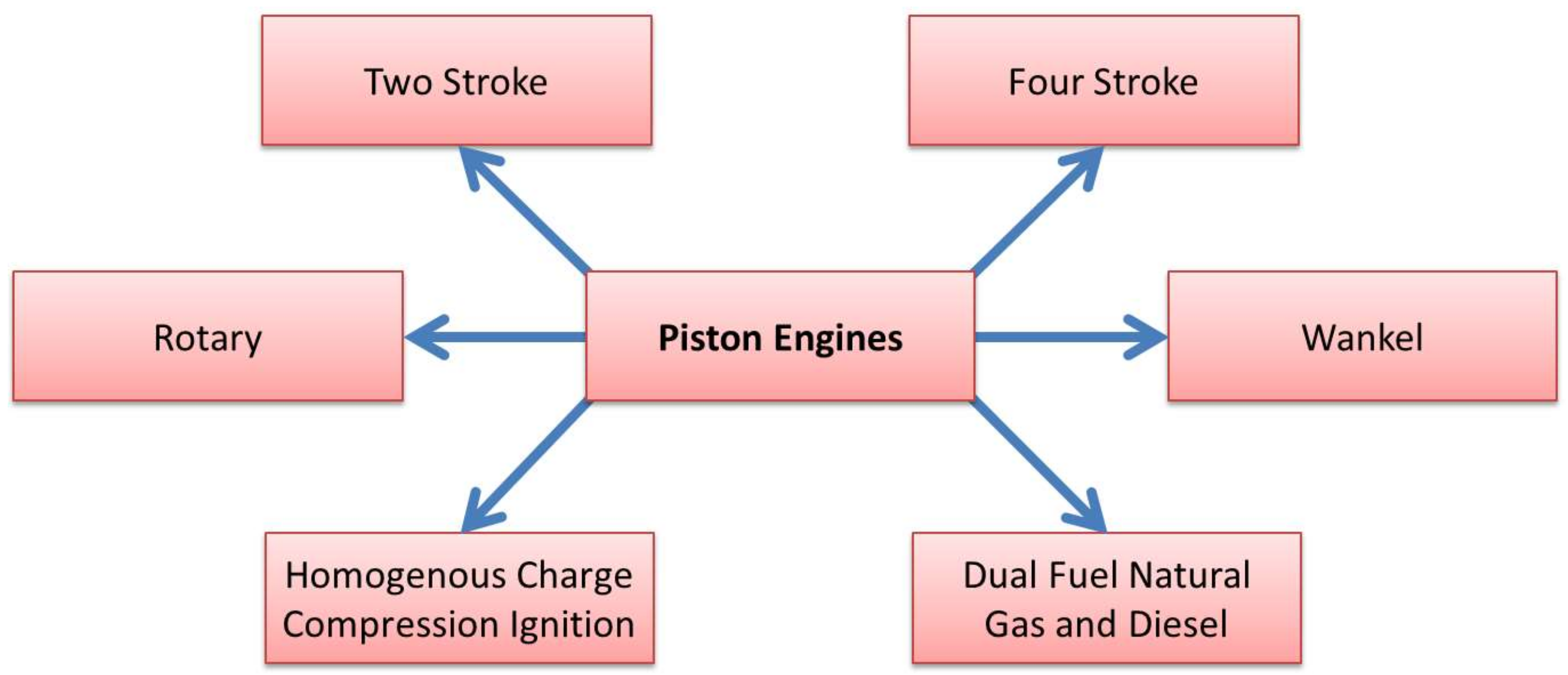
The piston engines that are popular in remotely piloted aircraft are further classified into [46]:
- Two-stroke,
- Four-stoke,
- Wankel,
- Homogenous-charge ignition engine, and
- Duel fuel engine.
These engine classifications are illustrated in Figure 3. Two stroke engines are commonly air cooled, light-weight, and do not need any additional lubrication as the oil and fuel is mixed. Two-stroke engines have a high power-to-weight ratio, are well-proven technology, and are efficient. Some shortcomings of piston engines include the inherent noise, limited altitude ceiling, and carbon-based emissions [47]. Four stroke engines are heavier than the two stroke engines and have a lower power-to-weight ratio than a two stroke engine; however, four stroke engines have greater efficiency and a longer expected lifespan. The Wankel engine is also a four stroke engine; it has a working part which resembles the reuleaux triangle with slightly convex sides. This part in the Wankel engine performs the four-strokes cycle in an oval-like housing [46]. Wankel engines have a higher power-to-weight ratio but produce less torque. A homogenous-charge compression ignition engine combines both the advantages of diesel and petrol engines and the ignition occurs naturally through compression (similar to a diesel engine) rather than ignition through a spark plug. Dual-fuel and high-compression engines work on a similar principle to a diesel engine where it can be fired by multiple fuels. It is capable of reducing nitrogen oxide emissions by 66% [46].
2.4.2. Gas Turbine Engine
Gas turbines are divided into:
- turboprop,
- turbojet,
- turbofan, and
- turboshaft.
These engines work on the Brayton cycle principle. The turbofan and the turbojet are referred to as thrust-producing engines, while the turboshaft and the turboprop are referred to as power-producing engines. Figure 4 illustrates the division of the gas turbine into these four subcategories. Gas turbine engines are mostly used in high-endurance and high-altitude RPAS. This requirement is suited to the gas turbines’ superior efficiency. The major advantage of the gas turbine engine is a very high power-to-weight ratio; however, a major drawback is the high fuel consumption at non-optimum conditions or conditions not favorable to the engine. These often occur in low-speed and idling scenarios. Due to high turbine combustor temperatures, emissions, such as nitrogen oxides and unburnt hydrocarbons, can be produced by a turbine engine. With low fuel efficiency comes high mission cost, and as with piston engines, there are environmental issues associated with the operation of gas turbine engines [48].
3. Hybridization
A hybrid system integrates the advantage of different systems to create a more efficient system. The advantages of hybrid electric propulsion (HEP) systems include fuel saving, efficiency, and less pollution [49]. The advantages of the hybrid system over the conventional systems have been previously studied in terms of the drive train efficiency [50] and the electric power system [51]. In both studies, favorable increases in efficiency are reported.
3.1. Types of Hybrid Using Internal Combustion Engine
The first major type of hybrid propulsion system is the EM-Electric generator system combined with an ICE. This is the most common type of Hybrid system and is utilized in land, water, and aerial vehicle applications. These ICE-HEP systems are referred to as heavy hybrid systems and are the most extensively studied in the literature. These are classified according to architectures or system configuration, and these classifications are not limited to ICE-based HEP systems; they are applicable across all hybridization models [52].
3.1.1. Series Configuration
In a series configuration, the propeller is directly driven by an electric machine, which is illustrated in Figure 5. Note that although the term propeller is used here and throughout the discussion, this could easily be a fan or other piece of turbomachinery used for propulsion. The chemical energy of the fuel is converted into mechanical energy and then into electrical energy by a generator and finally stored in batteries. Then, the stored energy is fed into the electric machine that turns the propeller to produce propulsive power. This electrical energy can be stored in the battery or can be directly used to run the electric machine. Even though this is the simplest configuration, the multiple energy conversion paths result in significant energy loss [53,54]. The series configuration is much heavier, and is best suited for low-speed and high-torque applications. This system was first successfully used in a flight test a DA36 E-star. The manufacturer, Diamond Aircraft, indicates a potential 25% decrease in fuel consumption. The series configuration has been shown to be unsuitable for RPAS/UAS applications, where it was estimated that a small UAV would result in an 8%, or 2.5 lb (1.13 kg), weight penalty for a 30-lb (13.61 kg) UAS [55].
3.1.2. Parallel Configuration
In a parallel configuration, the propeller can be driven either by the ICE, the electric machine, or a combination of both as shown in Figure 6. Both the ICE and the electric machine are connected through a mechanical clutch to the propeller that can either be in the path of the ICE or the electric machine, and can either engage or disengage according to the mode of operation. Alternatively, the ICE can drive both the propeller and electric machine as a generator to generate electricity and thereby charge the battery. This configuration is commonly used in hybrid land vehicles [56,57,58]. The major limitation of the parallel configuration is that the direct coupling to the propeller transmission limits the energy efficiency [59].
3.1.3. Series/Parallel Configuration
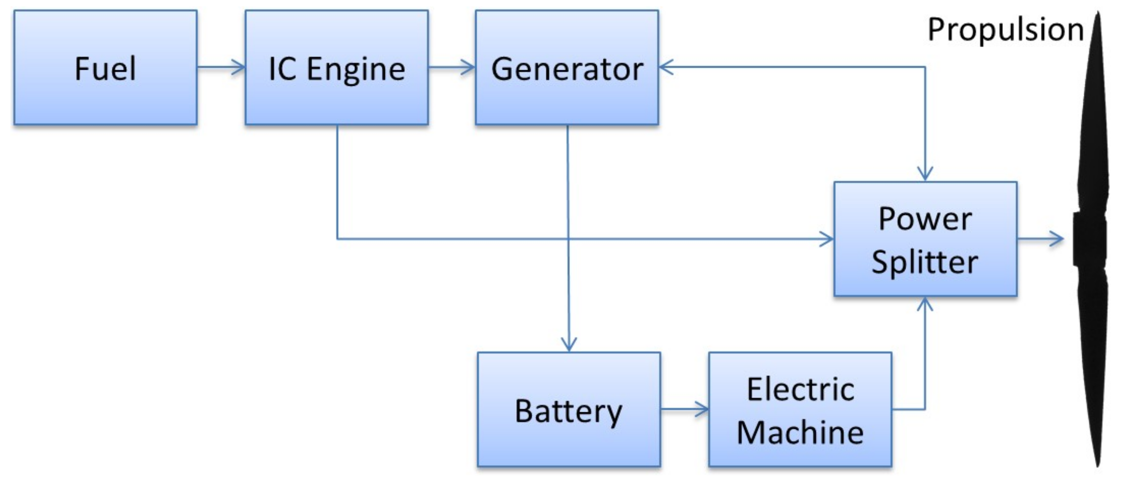
The final configuration is the series/parallel, which is the combination of a series and parallel configuration together; this configuration can also be referred to as a power-split configuration. The propeller, electric machine, generator, and ICE are all connected to a planetary gear that is also connected to the propeller. The ability to combine two power sources effectively improves the overall design of a power-split configuration and can result in fuel efficiency improvements while reducing emissions. Such a design can introduce complexities into the cost and control strategies that are required for its operation [60]. Unlike the clutch system of the parallel configuration, the power-split configuration does not include a clutch to transfer the mechanical energy to the propeller. This device is complex and heavy and is not practical for use in either manned or unmanned aircraft. As such, the power-split configuration is mostly used in land vehicles [61]. Figure 7 illustrates the flow of energy in the various possible paths for the power-split configuration.
3.2. Fuel-Cell Hybrid
In a fuel-cell only system, the electrical energy produced by the fuel cell is directly used to power the electric machine. Similarly, in a battery-only system, energy from the battery is used to power the electric machine. Finally, we could consider a photo-voltaic system, where the electrical energy produced by the solar cell is directly used to power the electric machine. It is then possible to consider combinations of these three systems.
3.2.1. Fuel-Cell–Battery
The low-energy density of a conventional battery for aircraft is unfavorable due to the inherent weight of their design [31]. In a fuel-cell–battery hybrid system, the low-power density of a fuel-cell system [62,63,64], in addition to the current electric power storage limitation of batteries [65], are both overcome by their use in combination. This allows the fuel-cell system to help achieve better fuel economy and performance while part of the load is powered from the batteries or super capacitors [66]. Such combination systems have shown improvement; for example, a Li-Po battery combination with a fuel cell shows an improvement in battery stack by over 7% relative to the fuel-cell-only system [67]. Other research shows a flying time increase from 470 to 970 min [26]. Another study outlined that the fuel-cell–battery combination could reduce fuel consumption by up to 3% by exploiting the efficiency of the fuel cell at part-load [24]. A fuel-cell–battery with hydrogen sourced from sodium borohydride demonstrated effective improvements to UAS endurance and this was validated through flight tests [68]. This hybrid system is mostly used by integrating a battery into the stack system to improve endurance. An example of this has shown an increase in stack efficiency of the hybrid by 7% [67]. Another example [69] has shown that a passive hybrid system could improve the efficiency of the fuel-cell system over 50%.
3.2.2. Fuel Cell-PV-Battery Hybrid
In the fuel-cell, PV, and battery hybrid system the combination consists of a fuel-cell, PV cells, and battery storage all utilized in tandem. In this three-part system, the three components can be combined in series and parallel in many different combinations to give a resultant hybrid system. There have been a few systems put forward in the literature. For example, the design put forward by Zafar and Gadalla [70] showed an increase in flight time of up to 10,670 s (2.96 h) from a conventional propulsion system time of 8286 s (2.3 h), which is an increase of 2384 s (0.66 h). Figure 8 shows a potential configuration of a three-part hybrid system utilizing a fuel-cell, PV cells, and batteries, similar to that in [26]. Figure 8 shows a typical PV–fuel cell hybrid system that uses a parallel configuration for the power sources. The system is connected to an electric machine that drives the propeller, where the electric machine can be powered either from a battery or the fuel cell.
3.2.3. Fuel-Cell Gas Turbine Hybrid
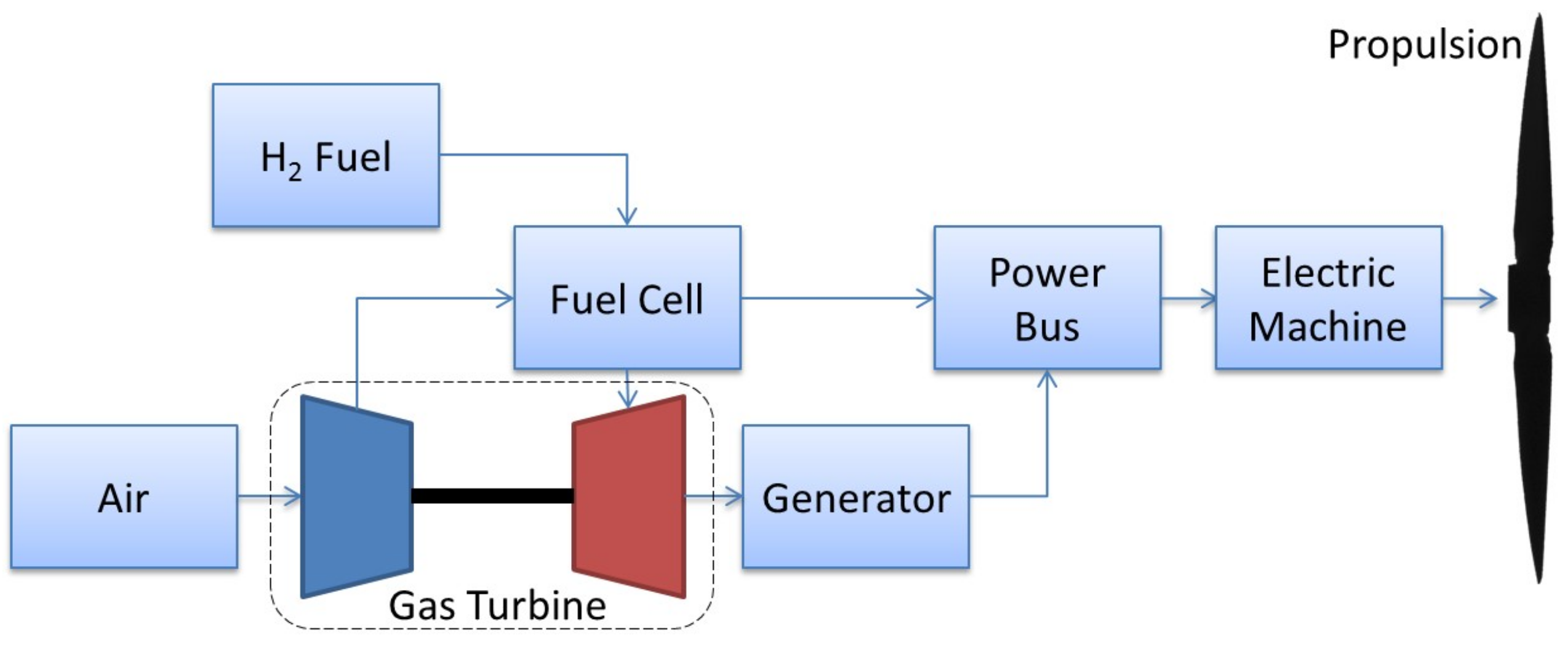
A fuel-cell gas turbine hybrid system uses a combination of a turbine engine-generator setup and a fuel-cell to produce power; specifically, the application of an SOFC fuel cell has been demonstrated. Here, the hybrid system may utilize a heat-recovery method [71,72]. This hybrid approach showed that such a system could achieve an improvement of up to 66.3% if the three-stack system was utilized [71]. This system is illustrated schematically in Figure 9.
Figure 9 shows an architecture of a fuel-cell—gas turbine hybrid. The system consists of a gas turbine and fuel-cell system that is connected to an electric machine that drives a propeller. The main fuel source is liquid hydrogen that is supplied to the fuel cell. The waste heat from the fuel cell is routed to an electric gas turbine generator and works with the principle of topping cycle heat recovery. Electric power from both sources is fed into a distribution network in a parallel architecture. The electric power distribution network supplies the power needed for operations, namely aircraft propulsion, the control system, and operational activities, such as radar and imaging.
3.3. ICE–PV Hybrid
The ICE and PV system is a specific type of hybrid system which is utilized to improve endurance. Specifically, the hybrid system utilizes PV cells to run the electric motors connected to the propeller during times when sufficient sun light is available, and the ICE is utilized otherwise. This model design has been implemented [34] with the goal of increasing the functionality of the aircraft (mission potential in terms of payload, etc.), but at the expense of a limited fuel supply such that the ultimate endurance is less than a PV–battery hybrid-powered aircraft. This is because when there is insufficient sunlight, the “hybrid” system will need to power the aircraft, and if this is dependent on a limited substance then there will be an ultimate limit to the endurance. In contrast, a PV–battery system can be engineered such that sufficient energy harvest during the day can power the aircraft continuously.
3.4. Electric Machine Technology
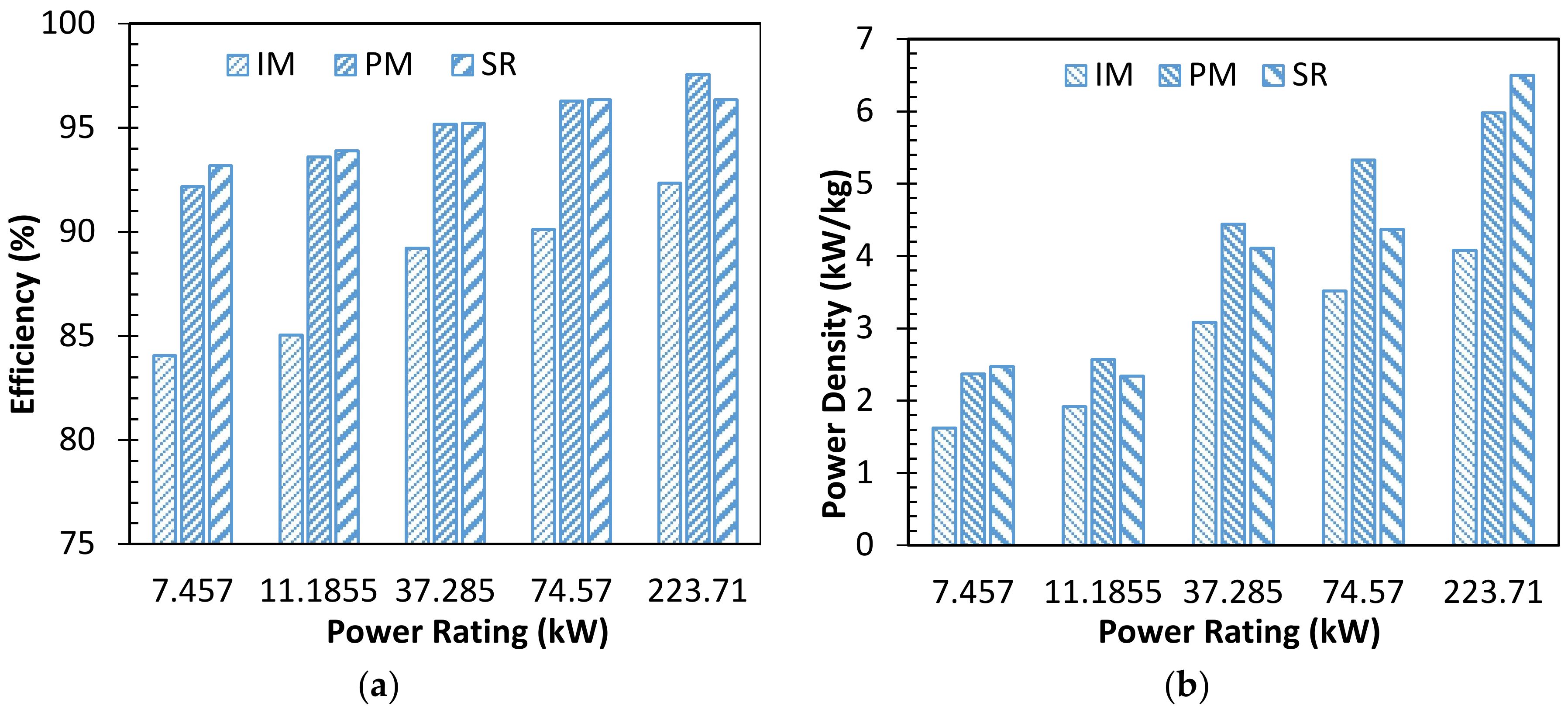
The present power generation technology in commercial aircraft consists of a separately mounted synchronous generator driven off by a Constant Speed Drive (CSD) ensuring 400 Hz supply at varying engine speeds as demanded by flight conditions. The synchronous generator has been proven to be reliable [73]; however; the need for a CSD penalizes the overall power density of the package. In RPAs, the power levels are lower than those of civil aircraft. It is generally considered that at low gear power transfer levels, the gear box power density is low [74] and as a result it can be inferred that use of a gearbox in mechanical power transmission at low power levels, such as those of RPASs, will achieve uncompetitive low power densities. Therefore, the need for a direct drive configuration of engine and electrical machine seems to be an obvious choice. Recent trends in more-electric aircraft (MEA) and all-electric aircraft (AEA) have also moved towards the direct integration of an electrical machine with an engine [75,76]. Alternative types of electrical machines and power electronic converters that offer low weight and high reliability have been studied for this purpose [77,78]. The authors of [79] compare permanent magnet (PM), switched reluctance (SR), and induction machines (IM) over a range of power levels and speed of 9000–10,000 rpm.
Figure 10 summarizes the study presented in [79]. The induction machine is found to be lower in efficiency and power density according to [79]. From Figure 10, it can be seen that at low power levels below 10 kW as required for RPASs, the power density of the induction machine is considerably lower than that of PM or SR machines. At power levels below 10 kW, both the SR and PM machines offer very similar performance. However, the SR machine requires a higher peak power rating of the power electronic converter. At power levels for RPAS systems, this peak power requirement may not pose a significant disadvantage and remains to be studied in detail.
The power density in also a function of the rated speed at which the electrical machine is designed. The authors of [80] show that for a range of 50 kW to 200 kW PM machine designs, the increase in designed surface rotor speed from 25 m/s to 200 m/s results in an increase in power density approximately from 1.8–2 kW/kg to 3.5–4 kW/kg. A similar study on SR machines remains to be investigated. However, a review on high-speed machines undertaken by the authors of [81] shows that at speeds above 50,000 rpm, the surface PM machine achieves higher merit compared to other machines. Therefore, for a given RPAS system the selection of either the PM or SR machine technology depends on the power requirement and speed.
4. Discussion
The major findings of this review are provided in Table 2. The four principal hybrid systems with applications to RPAS or UAVs have been identified:
- ICE parallel hybrid,
- ICE series hybrid,
- Fuel-cell hybrids, and
- PV hybrids.
Table 2 also identifies some of the key factors associated with each of these hybrid propulsion systems.
The concept of a turbo-electric hybrid system may be valid for use in the RPAS/UAS domain. Due to the high-rotational speeds of current turbine technologies, higher system power densities can be achieved with the use of high-speed machines and by elimination of mechanical gearing. The PM machine and the SR machines have been found to be the two candidates for application in RPAS systems. Various studies in the literature have shown that high RPM energy extraction from the turbo shaft is possible and will reduce the design complexity while reducing mechanical losses [82]. Excess energy extraction from a free turbine stage coupled with a battery-storage system may also hold benefits; however, increases in weight due to batteries is the obvious shortfall of the concept. Improvements in battery technology and improvements to energy density are ongoing. Energy storage through the use of light-weight supercapacitors may solve the issue of temporary energy storage and also have the advantage of a fast release for times of high-thrust requirements. The benefits of specific systems, outlined in Table 2, are universal when applied; however, weight, design, and mission requirements must be taken into consideration. The top-level requirements of an aircraft’s power system are always driven by power-to-weight ratios. When expanding into hybrid system options, weight considerations must be applied as more components are added to the overall system. A reduction and simplification of the power system is commonly favorable. Systems that do not use batteries for energy storage would be desirable; however, this is not commonly the case for electric aircraft. Utilizing solar panels on aircraft wings have been a popular and well-researched area as the power source is readily available from the sun; however, solar activity and time of day restrict the operational envelope of the aircraft. It is unclear at this stage which system, either a series or parallel, will be more favorable for use in RPAS. The mission requirements of each RPAS system is different as they perform different missions. If an RPAS is required to fly at night with a required range and endurance, then solar panels are not optimal. On the contrary, a day-time operation RPAS will see endurance benefits by harvesting energy from the sun. The scale of RPAS in which a hybrid system will be implemented is also a determining factor, as larger RPAS and UAS operate in a more aerodynamically efficient Reynolds number and can carry more weight relative to smaller aerial vehicles. Hybrid systems may in fact hold the key in larger drone scales.
5. Conclusions
This study has highlighted fundamental technologies to facilitate the development of long-endurance RPAS. Many current studies have outlined the benefit of isolated components to improve the efficiency of a propulsion system. The study attempts to review the way these technologies can be combined to form hybrid systems in multiple configurations. Of these many systems identified in the literature, those of specific interest in the design and development of unmanned aircraft have been detailed, including the potential benefits of each. Some case examples of these systems have been included, and are used to demonstrate the potential improvements in performance, specifically in terms of endurance. Further research is required to understand which system may provide the most benefit for the various scales and types of RPAS and UAS currently on the market, and this paper provides some visibility on hybridization and its benefits in the domain of RPAS.
Author Contributions
Mithun Abdul Sathar Eqbal, Nuwantha Fernando, Matthew Marino, and Graham Wild contributed equally to this work.
Conflicts of Interest
The authors declare no conflict of interest.
References
- Vasigh, B. Introduction to Air Transport Economics: From Theory to Applications; Taylor & Francis: Milton Park, UK, 2017. [Google Scholar]
- Joshi, D. Commercial Unmanned Aerial Vehicle (UAV) Market Analysis—Industry Trends, Companies and What You Should Know. Available online: http://www.businessinsider.com/commercial-uav-market-analysis-2017-8/?r=AU&IR=T (accessed on 29 December 2017).
- Wild, G.; Murray, J.; Baxter, G. Exploring civil drone accidents and incidents to help prevent potential air disasters. Aerospace 2016, 3, 22. [Google Scholar] [CrossRef]
- Villa, T.F.; Gonzalez, F.; Miljievic, B.; Ristovski, Z.D.; Morawska, L. An overview of small unmanned aerial vehicles for air quality measurements: Present applications and future prospectives. Sensors 2016, 16, 1072. [Google Scholar] [CrossRef] [PubMed]
- Gur, O.; Rosen, A. Optimizing electric propulsion systems for unmanned aerial vehicles. J. Aircr. 2009, 46, 1340–1353. [Google Scholar] [CrossRef]
- Ott, J.; Biezad, D. Design of a tube-launched UAV. In Proceedings of the AIAA 3rd “Unmanned Unlimited” Technical Conference, Chicago, IL, USA, 20–23 September 2004. [Google Scholar]
- Davat, B.; Astier, S.; Azib, T.; Bethoux, O.; Candusso, D.; Coquery, G.; Bernardinis, A.D.; Druart, F.; Francois, B.; Arregui, M.G.; et al. Fuel cell-based hybrid systems. In Proceedings of the 8th International Symposium on Advanced Electromechanical Motion Systems & Electric Drives Joint Symposium, Lille, France, 1–3 July 2009; pp. 1–11. [Google Scholar]
- Kallo, J.; Rathke, P.; Stephan, T.; Thalau, O.; Schirmer, J.; Mayer, F. Fuel Cell Systems for Aircraft Application & Antares DLR-H2 All-Electric Flying Testbed; American Institute of Aeronautics and Astronautics: Reston, VA, USA, 2013. [Google Scholar]
- Nishizawa, A.; Kallo, J.; Garrot, O.; Weiss-Ungethüm, J. Fuel cell and li-ion battery direct hybridization system for aircraft applications. J. Power Sources 2013, 222, 294–300. [Google Scholar] [CrossRef]
- Romeo, G.; Borello, F. Design and realization of a 2-seater aircraft powered by fuel cell electric propulsion. Aeronaut. J. 2010, 114, 281–297. [Google Scholar] [CrossRef]
- Keennon, M.; Grasmeyer, J. Development of two mavs and vision of the future of mav design. In Aiaa International Air and Space Symposium and Exposition: The Next 100 Years; American Institute of Aeronautics and Astronautics: Reston, VA, USA, 2003. [Google Scholar]
- Hepperle, M. Electric Flight—Potential and Limitations. Available online: https://www.google.com.au/url?sa=t&rct=j&q=&esrc=s&source=web&cd=1&cad=rja&uact=8&ved=0ahUKEwix87Hji6fYAhUFkpQKHQCsCBoQFggnMAA&url=https%3A%2F%2Fwww.mh-aerotools.de%2Fcompany%2Fpaper_14%2FMP-AVT-209-09.pdf&usg=AOvVaw0cJrkTWiexmgm4Wvez88CD (accessed on 23 November 2017).
- Avanzini, G.; Giulietti, F. Maximum range for battery-powered aircraft. J. Aircr. 2012, 50, 304–307. [Google Scholar] [CrossRef]
- Sliwinski, J.; Gardi, A.; Marino, M.; Sabatini, R. Hybrid-electric propulsion integration in unmanned aircraft. Energy 2017, 140, 1407–1416. [Google Scholar] [CrossRef]
- Traub, L.W. Range and endurance estimates for battery-powered aircraft. J. Aircr. 2011, 48, 703–707. [Google Scholar] [CrossRef]
- Mahlia, T.M.I.; Saktisahdan, T.J.; Jannifar, A.; Hasan, M.H.; Matseelar, H.S.C. A review of available methods and development on energy storage; technology update. Renew. Sustain. Energy Rev. 2014, 33, 532–545. [Google Scholar] [CrossRef]
- García, P.; Torreglosa, J.P.; Fernández, L.M.; Jurado, F. Viability study of a fc-battery-sc tramway controlled by equivalent consumption minimization strategy. Int. J. Hydrogen Energy 2012, 37, 9368–9382. [Google Scholar] [CrossRef]
- Savoye, F.; Venet, P.; Millet, M.; Groot, J. Impact of periodic current pulses on li-ion battery performance. IEEE Trans. Ind. Electron. 2012, 59, 3481–3488. [Google Scholar] [CrossRef]
- Panasonic. Panasonic Lithium Ion NCR18650 Specifications Version 13.11 r1. Available online: http://industrial.panasonic.com/cdbs/www-data/pdf2/ACA4000/ACA4000CE240%.pdf (accessed on 27 November 2017).
- Toussaint, G.; Stevens, P.; Akrour, L.; Rouget, R.; Fourgeot, F. Development of a rechargeable zinc-air battery. ECS Trans. 2010, 28, 25–34. [Google Scholar]
- Patel, K. Lithium-sulfur battery: Chemistry, challenges, cost, and future. J. Undergrad. Res. Univ. Ill. Chic. 2016, 9, 39–42. [Google Scholar] [CrossRef]
- Kraytsberg, A.; Ein-Eli, Y. Review on li–air batteries—Opportunities, limitations and perspective. J. Power Sources 2011, 196, 886–893. [Google Scholar] [CrossRef]
- Larminie, J.; Dicks, A.; Larminie, J.; Dicks, A. Fuel cell systems analysed. In Fuel Cell Systems Explained; John Wiley & Sons, Ltd.: Hoboken, NJ, USA, 2013; pp. 369–389. [Google Scholar]
- Gong, A.; Verstraete, D. Fuel cell propulsion in small fixed-wing unmanned aerial vehicles: Current status and research needs. Int. J. Hydrogen Energy 2017, 42, 21311–21333. [Google Scholar] [CrossRef]
- El-Sharkh, M.Y.; Rahman, A.; Alam, M.S.; Byrne, P.C.; Sakla, A.A.; Thomas, T. A dynamic model for a stand-alone pem fuel cell power plant for residential applications. J. Power Sources 2004, 138, 199–204. [Google Scholar] [CrossRef]
- Gadalla, M.; Zafar, S. Analysis of a hydrogen fuel cell-PV power system for small UAV. Int. J. Hydrogen Energy 2016, 41, 6422–6432. [Google Scholar] [CrossRef]
- Zakrisson, E. The Effect of Start/Stop Strategy on Pem Fuel Cell Degradation Characteristics; Chalmers University of Technology: Gothenburg, Sweden, 2011. [Google Scholar]
- Mekhilef, S.; Saidur, R.; Safari, A. Comparative study of different fuel cell technologies. Renew. Sustain. Energy Rev. 2012, 16, 981–989. [Google Scholar] [CrossRef]
- Sharaf, O.Z.; Orhan, M.F. An overview of fuel cell technology: Fundamentals and applications. Renew. Sustain. Energy Rev. 2014, 32, 810–853. [Google Scholar] [CrossRef]
- Stambouli, A.B.; Traversa, E. Solid oxide fuel cells (sofcs): A review of an environmentally clean and efficient source of energy. Renew. Sustain. Energy Rev. 2002, 6, 433–455. [Google Scholar] [CrossRef]
- Swider-Lyons, K.; Stroman, R.; Gould, B.D.; Rodgers, J.A.; Mackrell, J.; Schuette, M.; Page, G. Hydrogen fuel cells for small unmanned air vehicles. ECS Trans. 2014, 64, 963–972. [Google Scholar] [CrossRef]
- Kabir, E.; Kumar, P.; Kumar, S.; Adelodun, A.A.; Kim, K.-H. Solar energy: Potential and future prospects. Renew. Sustain. Energy Rev. 2018, 82, 894–900. [Google Scholar] [CrossRef]
- Partain, L.D. Solar Cells and Their Applications, 1st ed.; John Wiley & Sons, Inc.: Edison, NJ, USA, 1995; p. 349. [Google Scholar]
- Harmats, M.; Weihs, D. Hybrid-propulsion high-altitude long-endurance remotely piloted vehicle. J. Aircr. 1999, 36, 321–331. [Google Scholar] [CrossRef]
- Delmas, M.A.; Kahn, M.E.; Locke, S.L. The private and social consequences of purchasing an electric vehicle and solar panels: Evidence from california. Res. Econ. 2017, 71, 225–235. [Google Scholar] [CrossRef]
- Kaltenbrunner, M.; White, M.S.; Głowacki, E.D.; Sekitani, T.; Someya, T.; Sariciftci, N.S.; Bauer, S. Ultrathin and lightweight organic solar cells with high flexibility. Nat. Commun. 2012, 3, 770. [Google Scholar] [CrossRef] [PubMed]
- Green, M.A. Third Generation Photovoltaics Advanced Solar Energy Conversion; Springer: Berlin, Germany; New York, NY, USA, 2003. [Google Scholar]
- Habas, S.E.; Platt, H.A.S.; van Hest, M.F.A.M.; Ginley, D.S. Low-cost inorganic solar cells: From ink to printed device. Chem. Rev. 2010, 110, 6571–6594. [Google Scholar] [CrossRef] [PubMed]
- Jørgensen, M.; Norrman, K.; Gevorgyan, S.A.; Tromholt, T.; Andreasen, B.; Krebs, F.C. Stability of polymer solar cells. Adv. Mater. 2012, 24, 580–612. [Google Scholar] [CrossRef] [PubMed]
- Bloch, W.M.; Champness, N.R.; Doonan, C.J. X-ray crystallography in open-framework materials. Angew. Chem. Int. Ed. 2015, 54, 12860–12867. [Google Scholar] [CrossRef] [PubMed]
- Gao, P.; Gratzel, M.; Nazeeruddin, M.K. Organohalide lead perovskites for photovoltaic applications. Energy Environ. Sci. 2014, 7, 2448–2463. [Google Scholar] [CrossRef]
- Yang, W.S.; Noh, J.H.; Jeon, N.J.; Kim, Y.C.; Ryu, S.; Seo, J.; Seok, S.I. High-performance photovoltaic perovskite layers fabricated through intramolecular exchange. Science 2015, 348, 1234–1237. [Google Scholar] [CrossRef] [PubMed]
- Amos, J. Zephyr Solar Plane Set for Record Endurance Flight; BBC News: London, UK, 2010. [Google Scholar]
- Noth, A. History of Solar Flight. Available online: www.sky-sailor.ethz.ch/docs/History_of_Solar_Flight_v1.2-A.Noth_2006.pdf (accessed on 23 December 2017).
- Boucher, R.J. Sunrise, the world’s first solar-powered airplane. J. Aircr. 1985, 22, 840–846. [Google Scholar] [CrossRef]
- Adamski, M. Analysis of propulsion systems of unmanned aerial vehicles. J. Mar. Eng. Technol. 2017, 16, 1–7. [Google Scholar] [CrossRef]
- Zhou, L.; Liu, X.; Gao, Z. Internal Combustion Engine; China Machine Press: Beijing, China, 2004. [Google Scholar]
- Petrakopoulou, F.; Sánchez-Delgado, S.; Marugán-Cruz, C.; Santana, D. Improving the efficiency of gas turbine systems with volumetric solar receivers. Energy Convers. Manag. 2017, 149, 579–592. [Google Scholar] [CrossRef]
- Thounthong, P.; Rael, S. The benefits of hybridization. IEEE Ind. Electron. Mag. 2009, 3, 25–37. [Google Scholar] [CrossRef]
- Williamson, S.; Lukic, M.; Emadi, A. Comprehensive drive train efficiency analysis of hybrid electric and fuel cell vehicles based on motor-controller efficiency modeling. IEEE Trans. Power Electron. 2006, 21, 730–740. [Google Scholar] [CrossRef]
- Emadi, A.; Williamson, S.S.; Khaligh, A. Power electronics intensive solutions for advanced electric, hybrid electric, and fuel cell vehicular power systems. IEEE Trans. Power Electron. 2006, 21, 567–577. [Google Scholar] [CrossRef]
- Bataller-Planes, E.; Lapena-Rey, N.; Mosquera, J.; Orti, F.; Oliver, J.A.; Garcia, O.; Moreno, F.; Portilla, J.; Torroja, Y.; Vasic, M.; et al. Power balance of a hybrid power source in a power plant for a small propulsion aircraft. In Proceedings of the 2008 IEEE Power Electronics Specialists Conference, Rhodes, Greece, 15–19 June 2008; pp. 295–301. [Google Scholar]
- Jalil, N.; Kheir, N.A.; Salman, M. A rule-based energy management strategy for a series hybrid vehicle. In Proceedings of the 1997 American Control Conference (Cat. No.97CH36041), Las Cruces, NM, USA, 4–6 June 1997; Volume 681, pp. 689–693. [Google Scholar]
- Wang, H.; Huang, Y.; He, H.; Lv, C.; Liu, W.; Khajepour, A. Chapter 5—Energy management of hybrid electric vehicles a2—Zhang, Hui. In Modeling, Dynamics and Control of Electrified Vehicles; Cao, D., Du, H., Eds.; Woodhead Publishing: Sawston, UK, 2018; pp. 159–206. [Google Scholar]
- Harmon, F.G. Neural Network Control of a Parallel Hybrid-Electric Propulsion System for a Small Unmanned Aerial Vehicle. Ph.D. Thesis, University of California, Davis, CA, USA, 2005. [Google Scholar]
- Galvagno, E.; Morina, D.; Sorniotti, A.; Velardocchia, M. Drivability analysis of through-the-road-parallel hybrid vehicles. Meccanica 2013, 48, 351–366. [Google Scholar] [CrossRef] [Green Version]
- Minh, V.T.; Rashid, A.A. Automatic control of clutches and simulations for parallel hybrid vehicles. Int. J. Autom. Technol. 2012, 13, 645–651. [Google Scholar] [CrossRef]
- Pennestrì, E.; Mariti, L.; Valentini, P.P.; Mucino, V.H. Efficiency evaluation of gearboxes for parallel hybrid vehicles: Theory and applications. Mech. Mach. Theory 2012, 49, 157–176. [Google Scholar] [CrossRef]
- Hung, J.Y.; Gonzalez, L.F. On parallel hybrid-electric propulsion system for unmanned aerial vehicles. Prog. Aerosp. Sci. 2012, 51, 1–17. [Google Scholar] [CrossRef] [Green Version]
- Wall, T.J.; Meyer, R. A survey of hybrid electric propulsion for aircraft. In Proceedings of the 53rd AIAA/SAE/ASEE Joint Propulsion Conference, Atlanta, GA, USA, 10–12 July 2017. [Google Scholar]
- Chau, K.T.; Wong, Y.S. Overview of power management in hybrid electric vehicles. Energy Convers. Manag. 2002, 43, 1953–1968. [Google Scholar] [CrossRef]
- Jossen, A.; Garche, J.; Doering, H.; Goetz, M.; Knaupp, W.; Joerissen, L. Hybrid systems with lead–acid battery and proton-exchange membrane fuel cell. J. Power Sources 2005, 144, 395–401. [Google Scholar] [CrossRef]
- Kim, T.; Kwon, S. Design and development of a fuel cell-powered small unmanned aircraft. Int. J. Hydrogen Energy 2012, 37, 615–622. [Google Scholar] [CrossRef]
- Verstraete, D.; Cazzato, L.; Romeo, G. Preliminary design of a fuel-cell-based hybrid-electrical UAV. In Proceedings of the 28th Congress of the International Council of the Aeronautical Sciences, Brisbane, Australia, 23–28 September 2012; Volume 1, pp. 422–431. [Google Scholar]
- Fathabadi, H. High thermal performance lithium-ion battery pack including hybrid active–passive thermal management system for using in hybrid/electric vehicles. Energy 2014, 70, 529–538. [Google Scholar] [CrossRef]
- Motapon, S.N.; Dessaint, L.A.; Al-Haddad, K. A comparative study of energy management schemes for a fuel-cell hybrid emergency power system of more-electric aircraft. IEEE Trans. Ind. Electron. 2014, 61, 1320–1334. [Google Scholar] [CrossRef]
- Renau, J.; Sánchez, F.; Lozano, A.; Barroso, J.; Barreras, F. Analysis of the performance of a passive hybrid powerplant to power a lightweight unmanned aerial vehicle for a high altitude mission. J. Power Sources 2017, 356, 124–132. [Google Scholar] [CrossRef]
- Kim, K.; Kim, T.; Lee, K.; Kwon, S. Fuel cell system with sodium borohydride as hydrogen source for unmanned aerial vehicles. J. Power Sources 2011, 196, 9069–9075. [Google Scholar] [CrossRef]
- Verstraete, D.; Lehmkuehler, K.; Gong, A.; Harvey, J.R.; Brian, G.; Palmer, J.L. Characterisation of a hybrid, fuel-cell-based propulsion system for small unmanned aircraft. J. Power Sources 2014, 250, 204–211. [Google Scholar] [CrossRef]
- Zafar, S.; Gadalla, M. Evaluation of an integrated fuel cell-PV panel system as a hybrid UAV powerplant. In Proceedings of the ASME 2012 International Mechanical Engineering Congress and Exposition, Houston, TX, USA, 9–15 November 2012; pp. 1387–1392. [Google Scholar]
- Aguiar, P.; Brett, D.J.L.; Brandon, N.P. Solid oxide fuel cell/gas turbine hybrid system analysis for high-altitude long-endurance unmanned aerial vehicles. Int. J. Hydrogen Energy 2008, 33, 7214–7223. [Google Scholar] [CrossRef]
- Tornabene, R.T.; Freeh, J.E.; Steffen, C.J., Jr.; Wang, X.-Y.J.; Himansu, A. Hybrid Solid Oxide fuel Cell/Gas Turbine System Design for High Altitude Long Endurance Aerospace Missions—NASA/TM-2006-214328; NASA Glenn Research Center: Cleveland, OH, USA, 2006. [Google Scholar]
- Briggs, S.J.; Bartos, M.J.; Arno, R.G. Reliability and availability assessment of electrical and mechanical systems. IEEE Trans. Ind. Appl. 1998, 34, 1387–1396. [Google Scholar] [CrossRef]
- Kiel, E. Drive Solutions Mechatronics for Production and Logistics; Springer: Berlin/Heidelberg, Germany, 2008. [Google Scholar]
- Raimondi, G.M.; Sawata, T.; Holme, M.; Barton, A.; White, G.; Coles, J.; Mellor, P.H.; Sidell, N. Aircraft embedded generation systems. In Proceedings of the 2002 International Conference on Power Electronics, Machines and Drives (Conf. Publ. No. 487), Bath, UK, 4–7 June 2002; pp. 217–222. [Google Scholar]
- Fernando, W.U.N.; Barnes, M.; Marjanovic, O. Direct drive permanent magnet generator fed AC-DC active rectification and control for more-electric aircraft engines. IET Electr. Power Appl. 2011, 5, 14–27. [Google Scholar] [CrossRef]
- Fernando, N.; Vakil, G.; Arumugam, P.; Amankwah, E.; Gerada, C.; Bozhko, S. Impact of Soft Magnetic Material on Design of High-Speed Permanent-Magnet Machines. IEEE Trans. Ind. Electron. 2017, 64, 2415–2423. [Google Scholar] [CrossRef]
- Fernando, W.U.N.; Arumugam, P.; Gerada, C. Design of a Stator for a High-Speed Turbo-generator with Fixed Permanent Magnet Rotor Radius and Volt-Ampere Constraints. IEEE Trans. Energy Convers. 2018. [Google Scholar] [CrossRef]
- Krishnan, R.; Bharadwaj, A.S. A comparative study of various motor drive systems for aircraft applications. In Proceedings of the 1991 IEEE Industry Applications Society Annual Meeting, Dearborn, MI, USA, 28 September–4 October 1991; Volume 1, pp. 252–258. [Google Scholar]
- Van der Geest, M.; Polinder, H.; Ferreira, J.A.; Christmann, M. Power Density Limits and Design Trends of High-Speed Permanent Magnet Synchronous Machines. IEEE Trans. Transp. Electrif. 2015, 1, 266–276. [Google Scholar] [CrossRef]
- Gerada, D.; Mebarki, A.; Brown, N.L.; Gerada, C.; Cavagnino, A.; Boglietti, A. High-Speed Electrical Machines: Technologies, Trends, and Developments. IEEE Trans. Ind. Electron. 2014, 61, 2946–2959. [Google Scholar] [CrossRef]
- Malkamäki, M.; Jaatinen-Värri, A.; Honkatukia, A.; Backman, J.; Larjola, J. A high efficiency microturbine concept. In Proceedings of the 11th European Conference on Turbomachinery Fluid Dynamics and Thermodynamics, Madrid, Spain, 23–25 March 2015. [Google Scholar]
- Hiserote, R.; Harmon, F. Analysis of hybrid-electric propulsion system designs for small unmanned aircraft systems. In Proceedings of the 8th Annual International Energy Conversion Engineering Conference, Nashville, TN, USA, 25–28 July 2010. [Google Scholar]
- Harmon, F.G.; Frank, A.A.; Chattot, J.-J. Conceptual design and simulation of a small hybrid-electric unmanned aerial vehicle. J. Aircr. 2006, 43, 1490–1498. [Google Scholar] [CrossRef]
- Glassock, R.; Hung, J.Y.; Gonzalez, L.F.; Walker, R.A. Design, modelling and measurement of a hybrid powerplant for unmanned aerial systems. Aust. J. Mech. Eng. 2008, 6, 69–78. [Google Scholar] [CrossRef]
- Donateo, T.; Spedicato, L. Fuel economy of hybrid electric flight. Appl. Energy 2017, 206, 723–738. [Google Scholar] [CrossRef]
- Merical, K.; Beechner, T.; Yelvington, P. Hybrid-electric, heavy-fuel propulsion system for small unmanned aircraft. SAE Int. J. Aerosp. 2014, 7, 126–134. [Google Scholar] [CrossRef]
- Gao, X.-Z.; Hou, Z.-X.; Guo, Z.; Chen, X.-Q. Reviews of methods to extract and store energy for solar-powered aircraft. Renew. Sustain. Energy Rev. 2015, 44, 96–108. [Google Scholar] [CrossRef]
- Gong, A.; Palmer, J.L.; Brian, G.; Harvey, J.R.; Verstraete, D. Performance of a hybrid, fuel-cell-based power system during simulated small unmanned aircraft missions. Int. J. Hydrogen Energy 2016, 41, 11418–11426. [Google Scholar] [CrossRef]
Figure 1.
Endurance of various fuel-cell powered aerial vehicles as developed over time. The overlaid exponential trend is statically significant at the 99.7% confidence level and is given in the inset.
Figure 1.
Endurance of various fuel-cell powered aerial vehicles as developed over time. The overlaid exponential trend is statically significant at the 99.7% confidence level and is given in the inset.
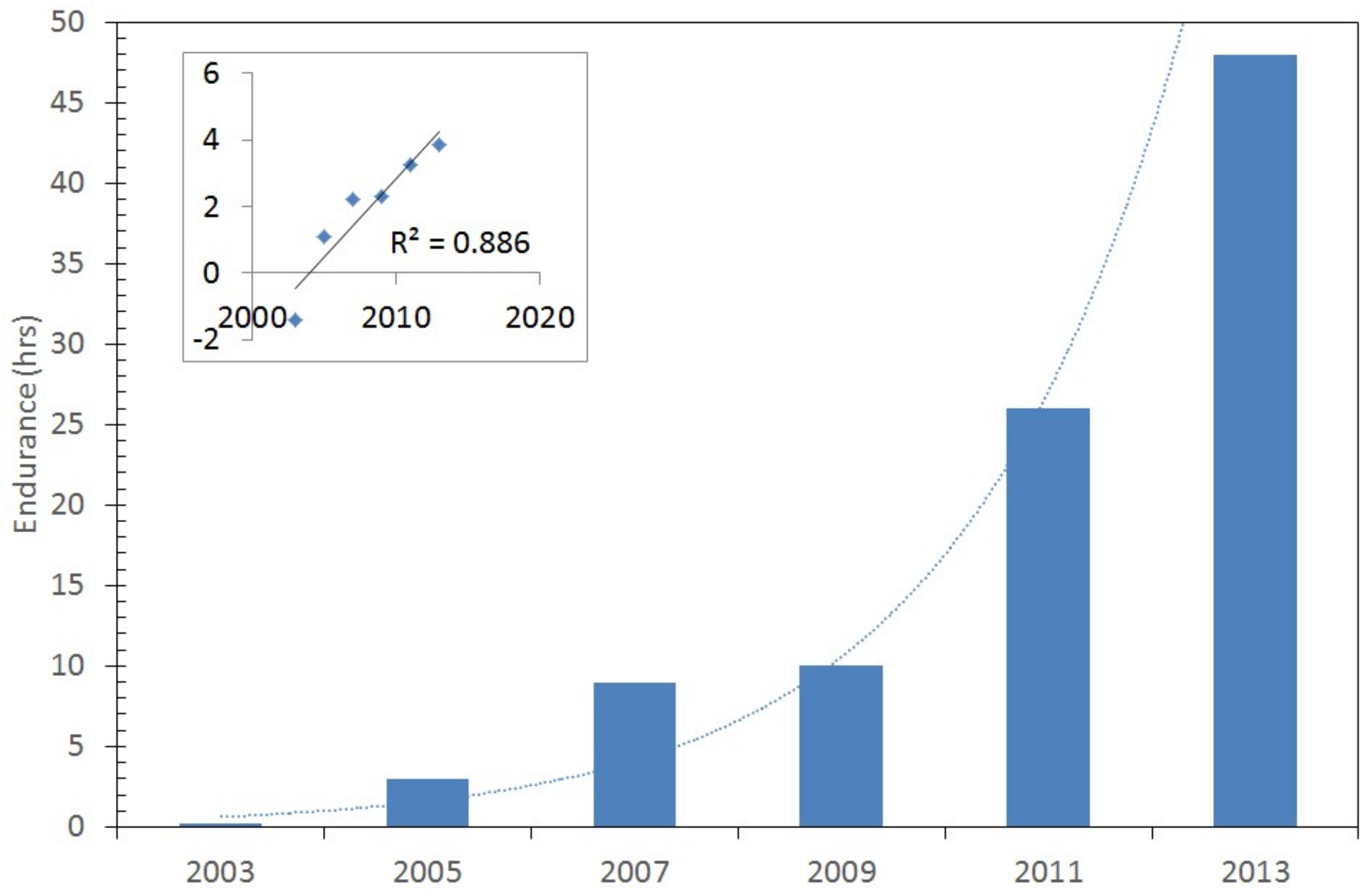
Figure 2.
Endurance of solar aerial vehicles as developed over time. The overlaid exponential trend is statically significant at the 99.6% confidence level and is given in the inset.
Figure 2.
Endurance of solar aerial vehicles as developed over time. The overlaid exponential trend is statically significant at the 99.6% confidence level and is given in the inset.
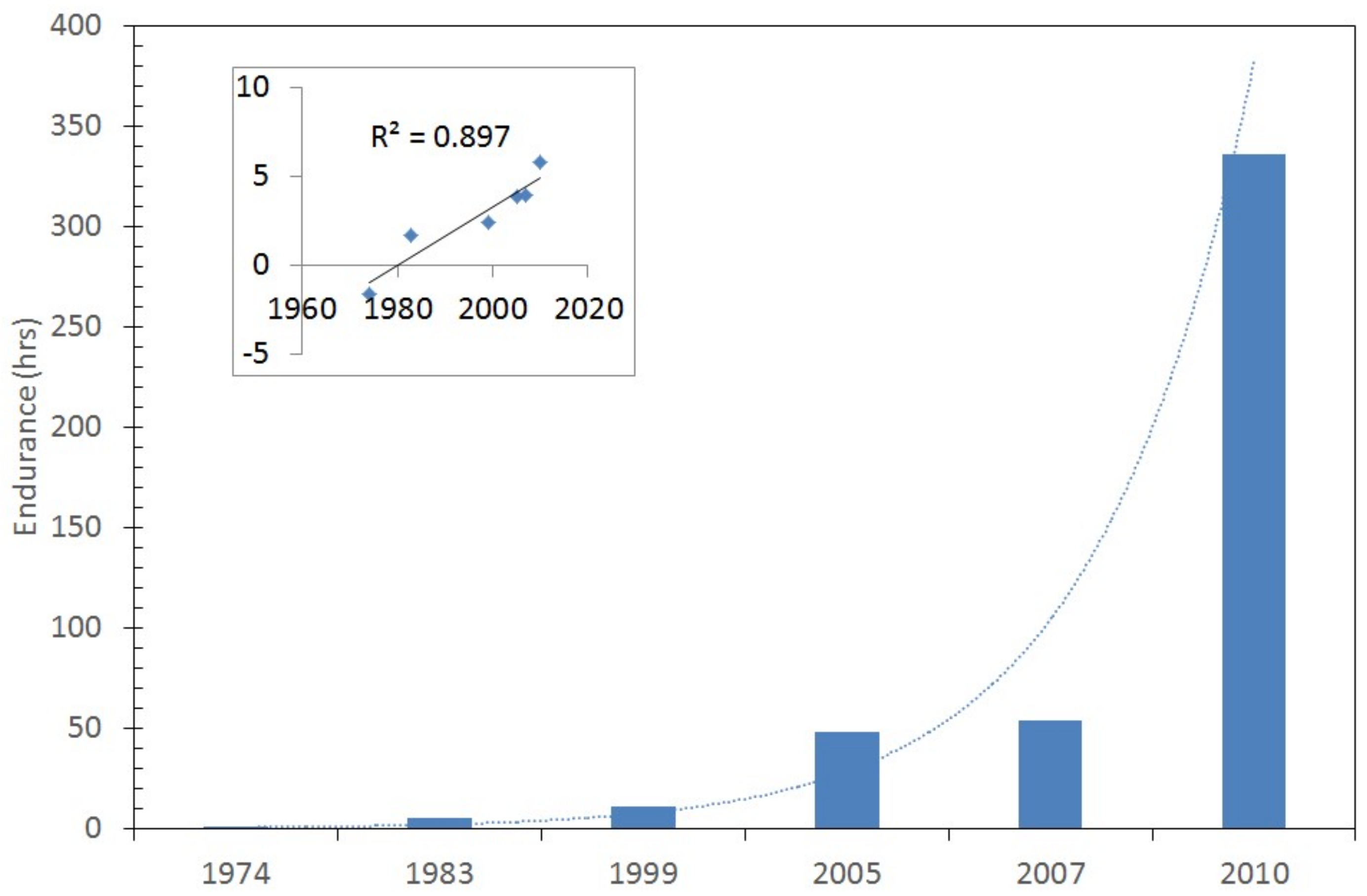
Figure 3.
Classification of Piston Engine.

Figure 4.
Types of gas turbine engine.
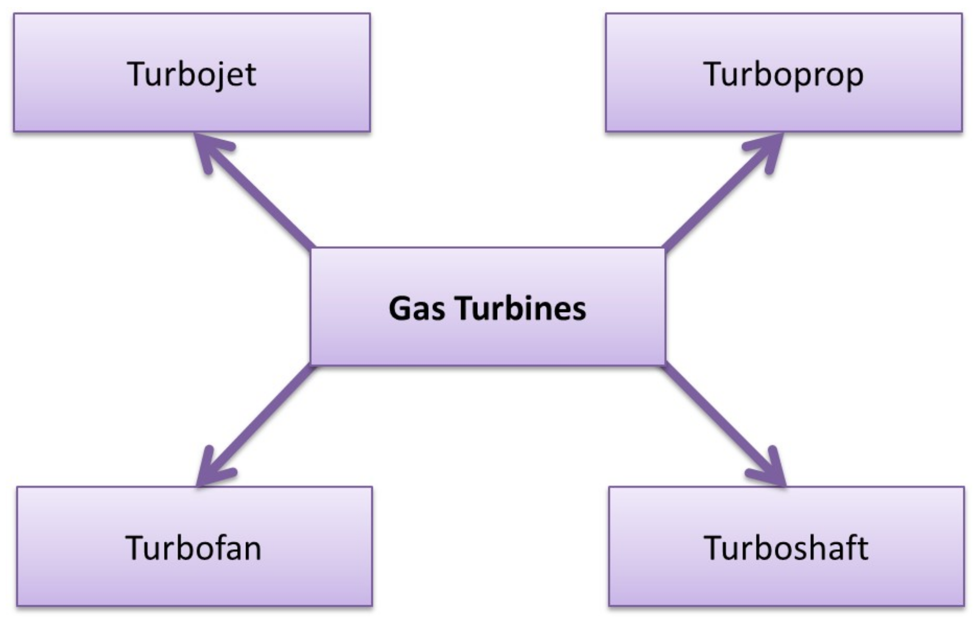
Figure 5.
A possible series configuration energy flow chart. IC: internal combustion.
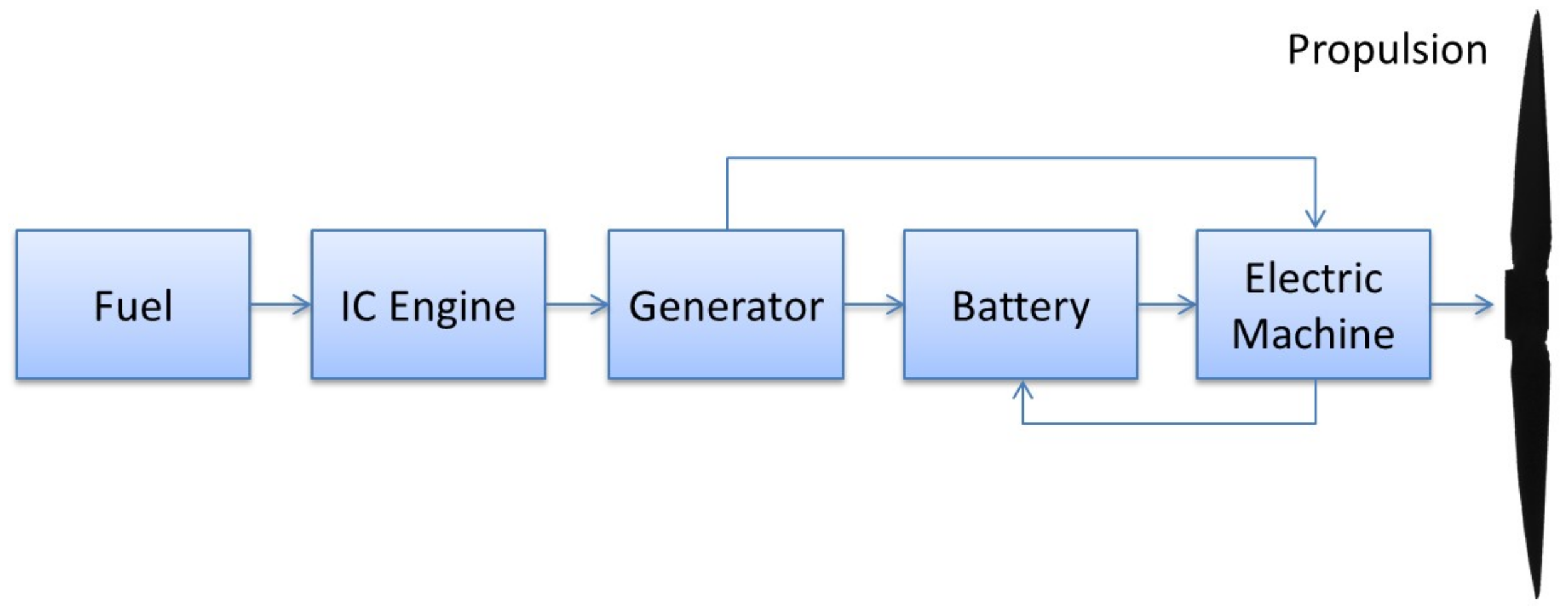
Figure 6.
Parallel configuration energy flow chart, with (left) and without (right) the ability of the IC engine to drive the electric machine and hence recharge the battery.
Figure 6.
Parallel configuration energy flow chart, with (left) and without (right) the ability of the IC engine to drive the electric machine and hence recharge the battery.
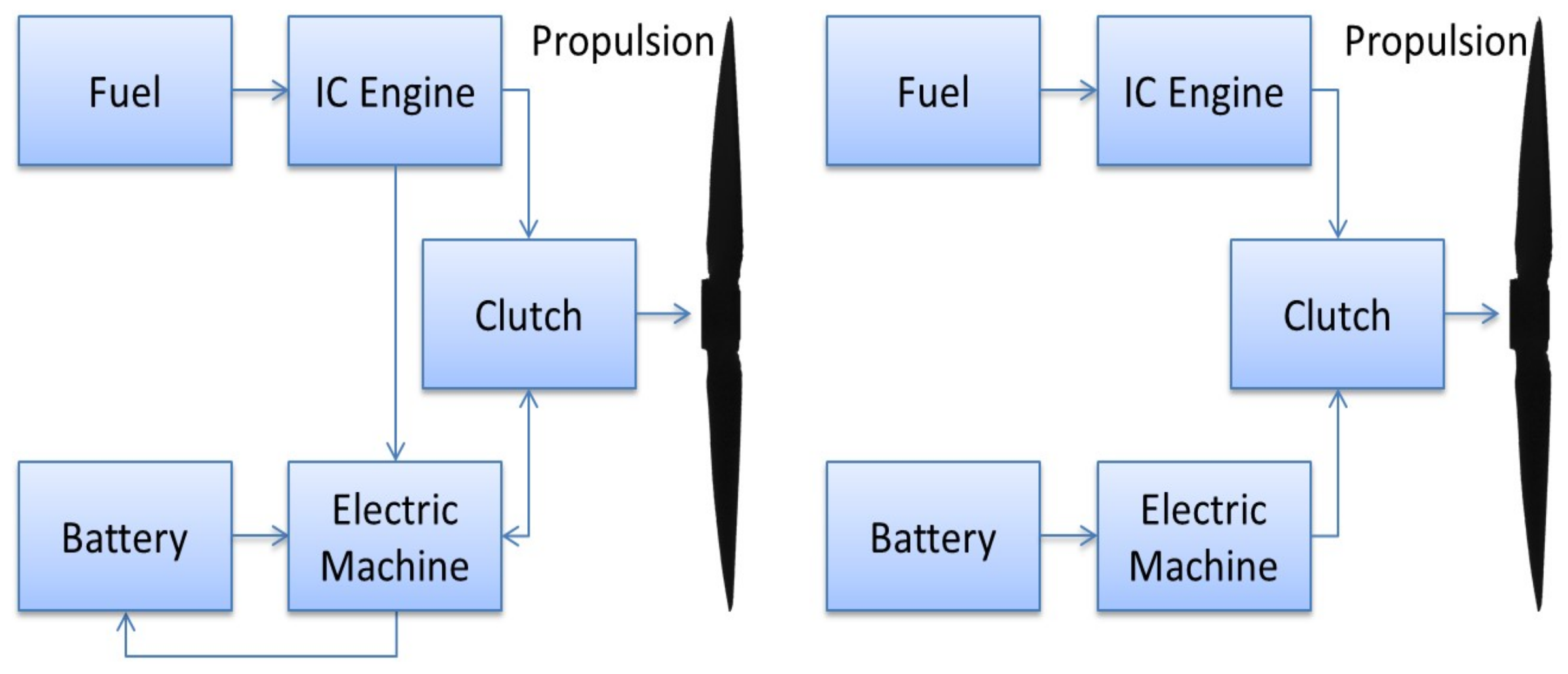
Figure 7.
Series/parallel or power-split configuration energy flow chart.

Figure 8.
Configuration of a potential fuel-cell + photovoltaic (PV) + battery hybrid system. In this example, the PV system is in series with a battery system, which are both in parallel with a fuel-cell system.
Figure 8.
Configuration of a potential fuel-cell + photovoltaic (PV) + battery hybrid system. In this example, the PV system is in series with a battery system, which are both in parallel with a fuel-cell system.
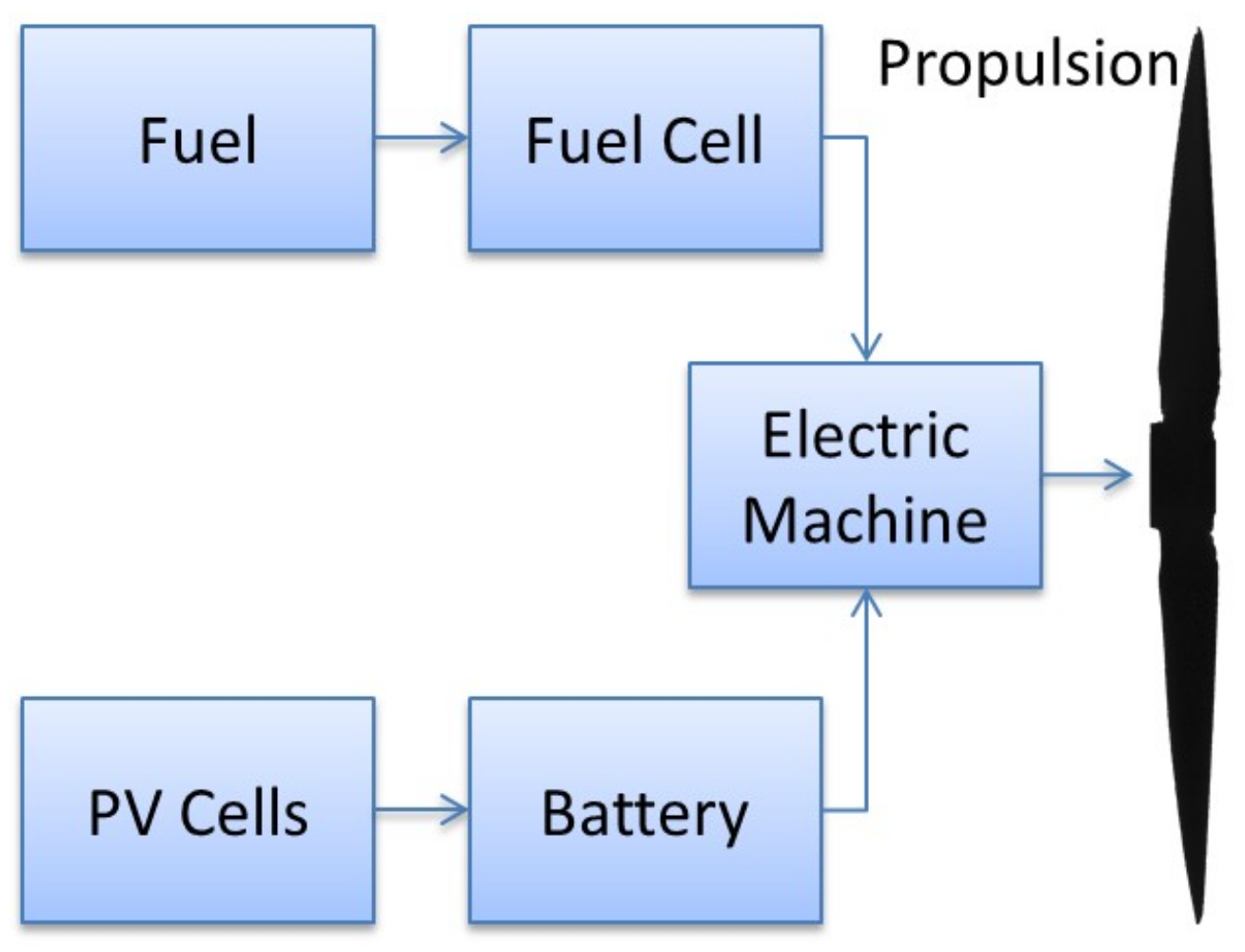
Figure 9.
A fuel-cell and gas turbine hybrid system. In this example, both the fuel cell and gas turbine are generating electricity which is then used to power an electrically driven propeller.
Figure 9.
A fuel-cell and gas turbine hybrid system. In this example, both the fuel cell and gas turbine are generating electricity which is then used to power an electrically driven propeller.

Figure 10.
Efficiency (a) and Power density (b) comparison of induction machines (IM), permanent magnet (PM) machines, and switched reluctance (SR) machines at different power levels designed for a rated speed in the neighborhood of 10,000 rpm [79].
Figure 10.
Efficiency (a) and Power density (b) comparison of induction machines (IM), permanent magnet (PM) machines, and switched reluctance (SR) machines at different power levels designed for a rated speed in the neighborhood of 10,000 rpm [79].


Table 1.
Specific energy of current and future chemical battery systems.
| System | Specific Eenergy (Wh/kg) | ||
|---|---|---|---|
| Theoretical 1 | Current | Expected in 2025 1 | |
| Li-Ion | 390 | 240 2 | 250 |
| Zn-air | 1090 | 442 3 | 500 |
| Li-S | 2570 | 375 4 | 1250 |
| Li-O2 | 3500 | 362 5 | 1750 |
Table 2.
Comparison of different hybrid systems and percentage of improvement.
| Model | Percentage of Improvement |
|---|---|
| Parallel Hybrid |
|
| Series Hybrid | |
| Fuel cell Hybrid | |
| PV hybrid |
© 2018 by the authors. Licensee MDPI, Basel, Switzerland. This article is an open access article distributed under the terms and conditions of the Creative Commons Attribution (CC BY) license (http://creativecommons.org/licenses/by/4.0/).
Share and Cite
MDPI and ACS Style
Abdul Sathar Eqbal, M.; Fernando, N.; Marino, M.; Wild, G. Hybrid Propulsion Systems for Remotely Piloted Aircraft Systems. Aerospace 2018, 5, 34. https://doi.org/10.3390/aerospace5020034
AMA Style
Abdul Sathar Eqbal M, Fernando N, Marino M, Wild G. Hybrid Propulsion Systems for Remotely Piloted Aircraft Systems. Aerospace. 2018; 5(2):34. https://doi.org/10.3390/aerospace5020034
Chicago/Turabian StyleAbdul Sathar Eqbal, Mithun, Nuwantha Fernando, Matthew Marino, and Graham Wild. 2018. "Hybrid Propulsion Systems for Remotely Piloted Aircraft Systems" Aerospace 5, no. 2: 34. https://doi.org/10.3390/aerospace5020034
Note that from the first issue of 2016, this journal uses article numbers instead of page numbers. See further details here.