Influence of Fluid–Thermal–Structural Interaction on Boundary Layer Flow in Rectangular Supersonic Nozzles

Department of Mechanical Engineering, University of Cincinnati, Cincinnati, OH 45221, USA
*
Author to whom correspondence should be addressed.
Aerospace 2018, 5(2), 33; https://doi.org/10.3390/aerospace5020033
Submission received: 30 December 2017
/
Revised: 17 March 2018
/
Accepted: 17 March 2018
/
Published: 27 March 2018
Abstract
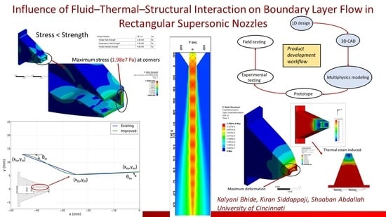
:The aim of this work is to highlight the significance of Fluid–Thermal–Structural Interaction (FTSI) as a diagnosis of existing designs, and as a means of preliminary investigation to ensure the feasibility of new designs before conducting experimental and field tests. The novelty of this work lies in the multi-physics simulations, which are, for the first time, performed on rectangular nozzles. An existing experimental supersonic rectangular converging/diverging nozzle geometry is considered for multi-physics 3D simulations. A design that has been improved by eliminating the sharp throat is further investigated to evaluate its structural integrity at design Nozzle Pressure Ratio (NPR 3.67) and off-design (NPR 4.5) conditions. Static structural analysis is performed by unidirectional coupling of pressure loads from steady 3D Computational Fluid Dynamics (CFD) and thermal loads from steady thermal conduction simulations, such that the simulations represent the experimental set up. Structural deformation in the existing design is far less than the boundary layer thickness, because the impact of Shock wave Boundary Layer Interaction (SBLI) is not as severe. FTSI demonstrates that the discharge coefficient of the improved design is 0.99, and its structural integrity remains intact at off-design conditions. This proves the feasibility of the improved design. Although FTSI influence is shown for a nozzle, the approach can be applied to any product design cycle, or as a prelude to building prototypes.
1. Introduction
Rectangular supersonic nozzles have been a topic of interest for many researchers [1,2,3,4,5,6] as they produce less noise compared to their circular counterparts and are easier to design and manufacture. Noise characteristics and flow structures in rectangular nozzles have been investigated experimentally and numerically using Reynolds Averaged Navier-Stokes (RANS) or Large Eddy Simulations (LES) to study the noise generation due to shock formation, turbulent mixing and screech tones [1,2,3]. A double-diamond shock pattern is present in rectangular nozzles with conical sections [3], because of the sharp throats present at over, ideally and under-expanded conditions. Throat shock strength causes wave drag and side loads due to shock reflections and affects structural integrity, which in turn affects the overall performance of a nozzle. This needs to be addressed further to evaluate the stresses and strains induced in the nozzle. Although finite element analysis was performed by Frate et al. [7] during the design phase of rectangular nozzles, the coupled effect of multi-physics modeling has not been previously addressed. In supersonic flow, the influence of Shock wave Boundary Layer Interaction (SBLI) on the structure is crucial and must be accounted for, as shown by Riley et al. [8]. Hence, Fluid–Thermal–Structural Interaction (FTSI) modeling provides an insight into the coupled effects of flow physics and structural integrity, at high operating pressures and temperatures. Considering these factors, multi-physics simulations are performed. Two nozzle designs are considered—(1) an existing, experimentally-tested design, which has in-nozzle shocks due to the sharp throat and (2) an improved design with smoothly-contoured nozzle walls, which has a greater discharge coefficient due to less blockage by the boundary layer as demonstrated earlier by the authors [9]. This design is further investigated under off-design conditions to simulate the maximum operating pressure ratio. If the design can withstand these loads, then it is safe at lower operating points.
2. Methodology
2.1. Governing Equations & Computational Methodology
3D steady RANS equations [10] are solved for compressible flow of air, modeled as an ideal gas. The k-omega SST turbulence model [11] is used for CFD simulations. Equations (1)–(4) represent the governing equations for conservation of mass, momentum and energy, where e is the internal energy per unit mass, P is the pressure, is the density and u, v, w are the x, y, z velocity component vectors. The viscous stress tensors, and , are defined in Equation (6). A density-based solver is used, and a second order upwind scheme is used for spatial discretization. Roe-FDS is used for convective fluxes. Fourier’s steady heat conduction Equation (7) is solved to account for the heat transfer.
Equations (8)–(10) represent the equation of motion, strain-displacement relationship and constitutive equation (Hooke’s law) [12], where xi, i = 1, 2, 3 are the components of the position vector x, t is the time, is the Cauchy stress tensor, fi are the body forces, is the mass density, ui is the displacement vector, is the strain, is the thermal part of the strain tensor and Cijkl is the elasticity tensor.
Since this work is a preliminary investigation of FTSI effects on the structural integrity and boundary layer flow, all simulations represent steady-state operation. Twenty Intel Xeon (2.6 Gigahertz) processor cores are used for each simulation, which took about 15–20 h to converge to 1 × 10⁻⁴ order of residual of the continuity equation, depending on the CFD mesh size of approximately 4 million cells.
2.2. Grid Resolution Study
A grid resolution study is conducted on the existing nozzle geometry at NPR 3.67. This is done by keeping the total thickness of prism layers the same for every grid, and by varying the refinement cell size for each grid level. The details of the grids and mass-averaged quantities at the throat and exit are presented in Table 1. Figure 2 shows the comparison of velocity magnitudes along the jet centerline for coarse, medium and fine grid levels, with the experimental data from Baier et al. [1]. The velocity magnitudes and mass-averaged quantities do not change significantly with each grid refinement. Hence, a coarse grid level is used for all simulations to save computational time.
Note that the experimental measurements start from x/De ≈ 0.82 and not at the nozzle exit i.e., x/De = 0. The error in the experimental measurements is ±1%. Figure 2 shows that the error between experimental data and simulated data is within 5% until 10 De, which is calculated using the following equation:
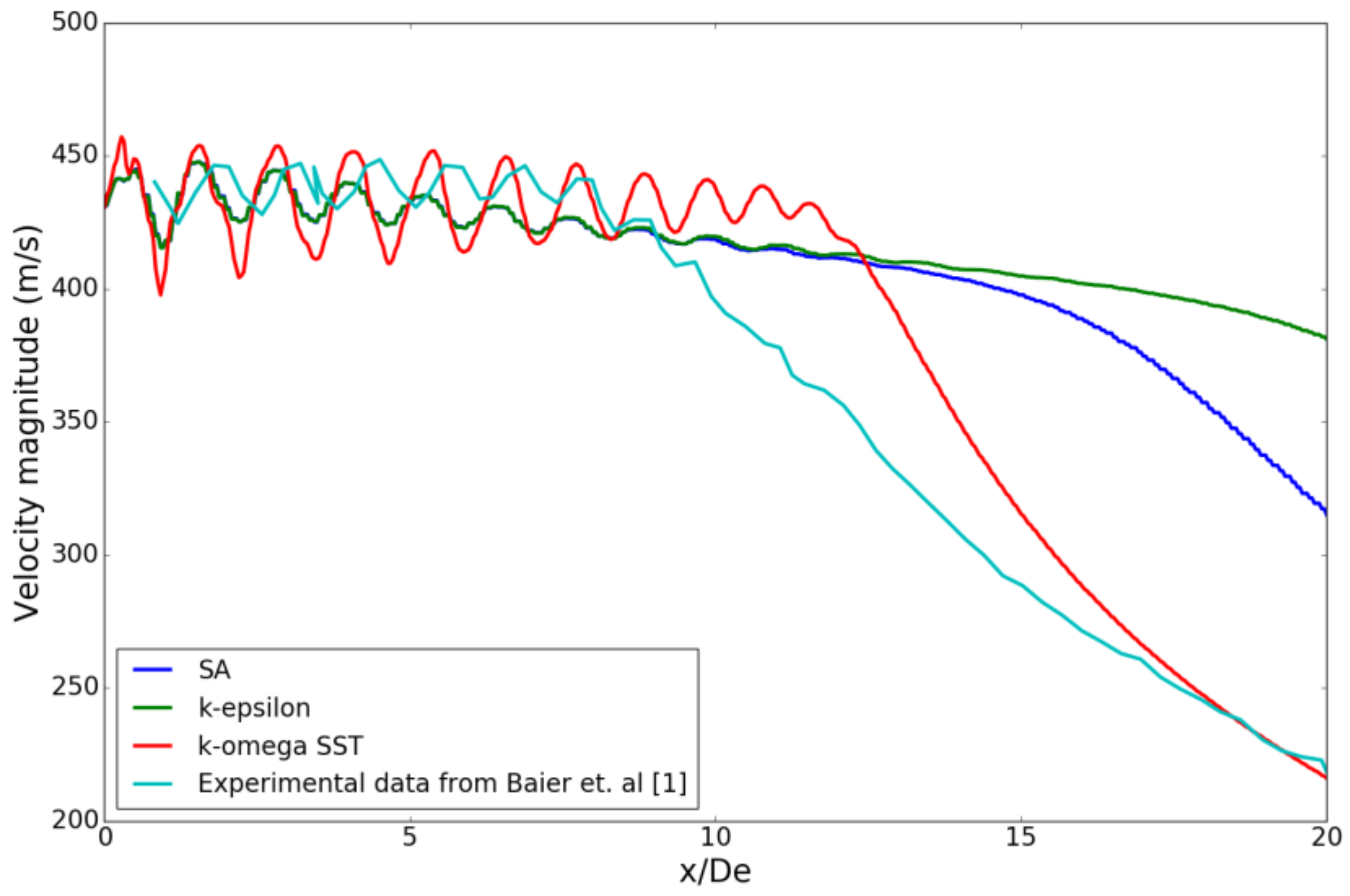
The literature by Georgiadis et al. [13], Truemner et al. [14] highlights that capturing initial jet growth region is still a difficulty for RANS modeling because the calculated jet mixing rates are generally lower than those exhibited by the experimental data, turbulence intensities are underestimated, and potential core lengths are overestimated by RANS for free jets. The turbulence model study (Figure 3) shows that k-epsilon and Spallart-Allmaras (SA) predict the shock cell amplitude better than k-omega SST, until a few diameters downstream of the nozzle exit. However, they do not capture the velocity decay accurately further downstream. Hence, k-omega SST is chosen for this study as it gives a good approximation of the overall trend in velocity decay. Previous literature on turbulence models and corrections [15] talks about the effects of compressibility on the dissipation rate of turbulent kinetic energy. Turbulence model and compressibility correction play a key role in capturing the shock cell amplitude. It appears that the error in validation is likely due to the underestimated dissipation rate of turbulent kinetic energy in the current RANS model.
2.3. Turbulence Model Study
A turbulence model study is conducted on the existing nozzle geometry, to ensure appropriate turbulence model selection. Three turbulence models [16], namely Spallart-Allmaras (SA), k-epsilon and Menter’s k-omega SST are used. Figure 3 shows a comparison of three turbulence models with the experimental data. k-omega SST predicts the velocity magnitudes more accurately, whereas the other turbulence models show large deviation in velocity magnitudes from 10 De to 20 De. k-omega SST is known for its better performance under adverse pressure gradients in boundary layers [11], hence it is used for all simulations.
2.4. Improved Nozzle Design
Wall curve for the improved design (shown in green) is generated using an in-house, Python-based design tool called Gencurve, developed by Bhide et al. [9]. This is a general-purpose curve generator for nozzles, inlets, ducts, etc. which uses cubic or higher order polynomials for generating curves. The tool outputs two curves for converging and diverging sections by matching their slope at the throat. The curves are then imported to a CAD package. Gencurve demonstrates the slope matching technique for generating curves as opposed to the super-ellipse method used by Dippold et al. [6]. Parametric B-spline based curve generation is another option in progress to obtain smoother wall curves as shown by Siddappaji et al. [17]. Figure 4 shows wall coordinates of the existing and improved design. Slope matching reduces throat shocks. This decreases the blockage caused by the boundary layer, hence the discharge and total pressure recovery coefficients increase to 0.99 and 0.974, respectively. The design is investigated further to evaluate the structural integrity at design and off-design conditions.
2.5. Fluid Thermal Structural Interaction
2.5.1. Challenges in FTSI
Data exchange and data mapping are important during FTSI simulations. Appropriate surface selection while importing the loads is equally important because it serves as boundary conditions to thermal and structural simulations. Mesh sizing and quality is crucial while mapping loads calculated by CFD. Mechanical and thermal loads affect the nozzle in supersonic flow. There are two ways to account for this—(1) Fluid–Structure Interaction (FSI), where the temperature and pressure on the nozzle walls are imported directly into the structural solver, then thermal strains and equivalent stresses are calculated; (2) FTSI, where the temperature and pressure on the nozzle walls are imported into a thermal solver to solve Fourier’s equations for steady-state heat conduction. The temperatures calculated by the thermal solver are then imported into the structural solver. Accurate prediction of heat transfer plays a key role as the static temperature gradient (Tin–Tex) in fluid flow through the existing nozzle design is approximately 92 K. Hence, heat transfer due to conduction is pronounced and not as trivial. Therefore, FTSI is accurate from a physics perspective since it accounts for the conductive heat transfer in the nozzle. Convective heat transfer is not considered in the thermal analysis, as conduction is the main contributor to thermal loads. Moreover, imported pressure loads represent the net force due to shear and normal pressure [18], hence using appropriate y+ is essential.
2.5.2. FTSI Workflow
Figure 5 shows one-way FTSI flowchart. This is a 1D to 3D approach for rectangular nozzle design, which is also applicable to other product design and development. Gencurve is used to add curvature to the nozzle walls, which are lofted in Solidworks [19] to obtain a 3D CAD model. It is simplified by removing bolt holes, drafts and other components. Figure 6 illustrates the FTSI methodology with appropriate data exchange for multi-physics modeling. 3D compressible RANS equations are solved on the fluid domain, which extends 50 De downstream of the nozzle exit. 15 prism layers with tetrahedral unstructured mesh are used to ensure y+ < 5. The mass-flow rate at the inlet and exit planes is monitored to ensure convergence. The nozzle inlet is modeled as a stagnation inlet, the nozzle walls are no-slip adiabatic walls and the domain is modeled as a free stream with atmospheric pressure and temperature, which corresponds to 101,325 Pa and 300 K.
CFD-calculated thermal loads along the nozzle walls are imported (as boundary conditions) to the steady-state thermal solver in the ANSYS Workbench version 18.1. The total heat flux and temperature on the nozzle are evaluated. The results from CFD and thermal simulations are then imported to the static structural module of the ANSYS Workbench. A tetrahedral mesh is used for structural analysis. Along with the imported pressure and temperature loads, gravity and a fixed support at the nozzle inlet are considered to simulate the experimental set up for cold jet, i.e., TR 1. Structural deformation, equivalent stress, strain and thermal strain are evaluated at design conditions, i.e., NPR 3.67, and off-design conditions, i.e., NPR 4.5, which is the highest NPR in the experimental facility for this design. Structural steel is used for all simulations [20].
3. Results
The influence of FTSI as a diagnosis of existing rectangular nozzle geometry, and for the preliminary investigation of the improved design is evaluated. The structural deformation and boundary layer thickness are computed for the existing design to study the effect of internal shock formation on boundary layer flow. Improved design is further evaluated at off-design conditions.
3.1. Structural Deformation and Boundary Layer Thickness
Figure 7 shows Mach number contours on major and minor axis symmetry planes in the existing nozzle. Oblique shock formation at the throat can be seen, which induces pressure loads on the nozzle due to shock reflection from the wall. The boundary layer becomes thicker due to the adverse pressure gradient imposed by an oblique shock wave. However, the boundary layer does not separate from the nozzle wall, hence the shocks are mild and the effect of SBLI is not as severe. Therefore, it does not cause large deformations in the nozzle. This is quantified by comparing the boundary layer thickness (δ) and maximum deformation (Δ). δ calculated from CFD is 1.23 mm at the nozzle exit and maximum Δ is 0.005 mm. Hence,
δ >> Δ
However, this becomes crucial when stronger shocks are formed and shows the importance of FTSI when structural deformations are in the order of boundary layer thickness, i.e., δ ≈ Δ.
3.2. Existing and Improved Design
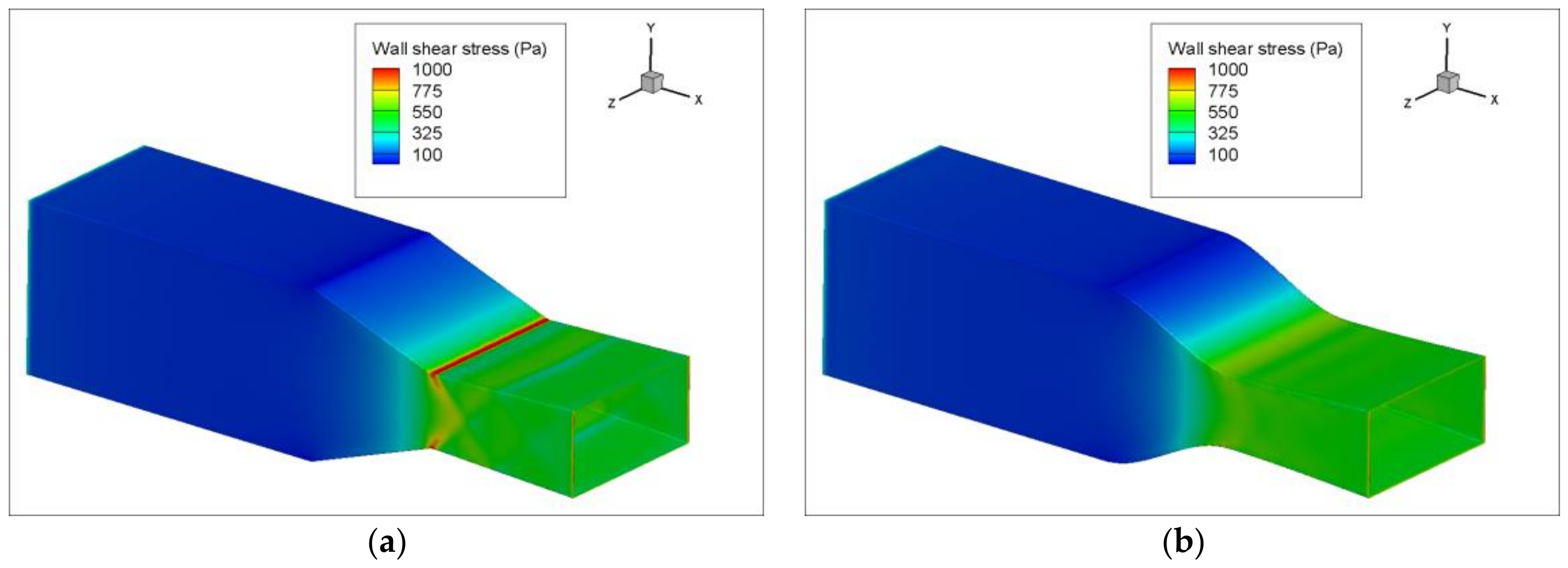
Very weak shocks are observed in the improved design due to the smooth nozzle wall curve which makes the CFD-computed forces lesser in this case. On the other hand, these forces are greater in the existing design due to internal shock formation, as shown in Figure 7. Figure 8 compares the wall shear stress on the existing and improved designs. It is higher on the existing nozzle due to shock formation. Figure 9 shows total pressure contours on the existing and improved designs.
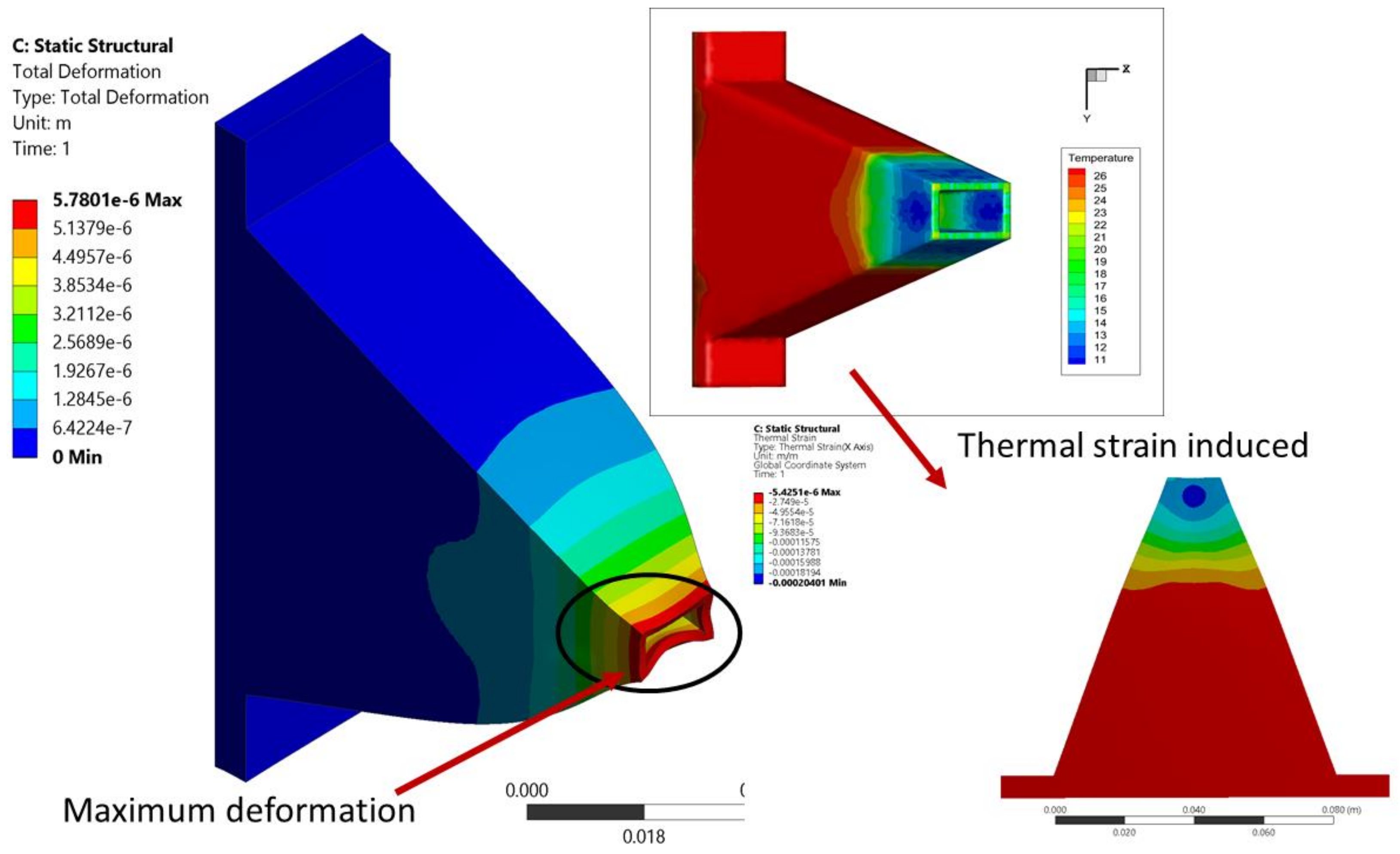
Figure 10 shows Von-Mises stress at NPR 4.5 for the improved design. It is maximum at corners since there are no fillets or drafts. It can be seen from Figure 10 that the structural integrity of this design remains intact at off-design conditions. Although maximum stress is induced on sharp corners at the exit, the design does not fail as the stress is less than the material strength. This makes the design safe at NPRs < 4.5. Total deformation and thermal strain are illustrated in Figure 11. Note that the deformations are exaggerated by 3× for better visualization. FTSI modeling indicates that the pressure and temperature loads are compressive in nature. This is because the simulations represent nozzle operation at atmospheric pressure and temperature, which are greater than the static pressure and temperature of the fluid at the nozzle exit. Hence, the loads are directed from the nozzle wall towards the fluid, which reduces the cross-sectional area at the nozzle exit.
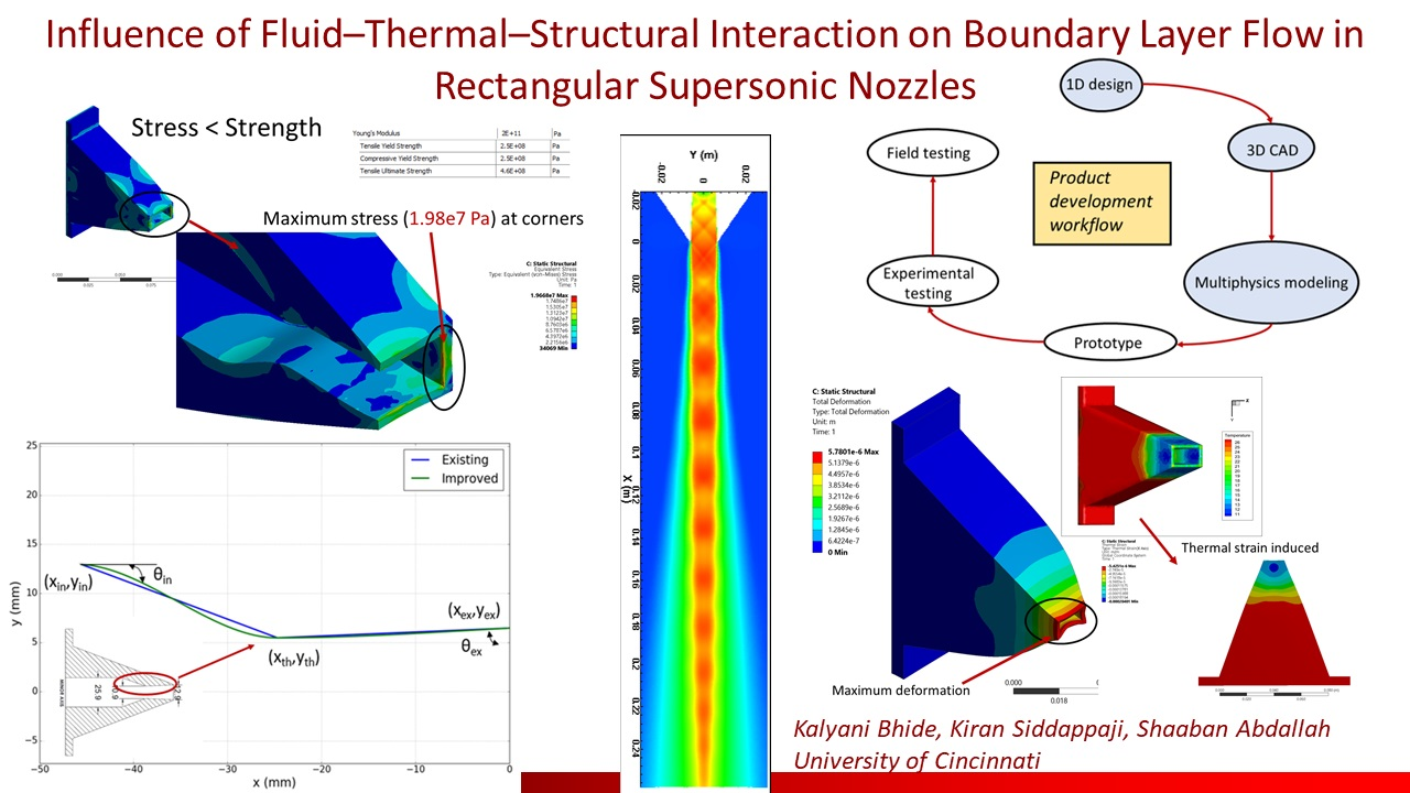
3.3. Multiphysics Modeling as a Prelude to Prototype
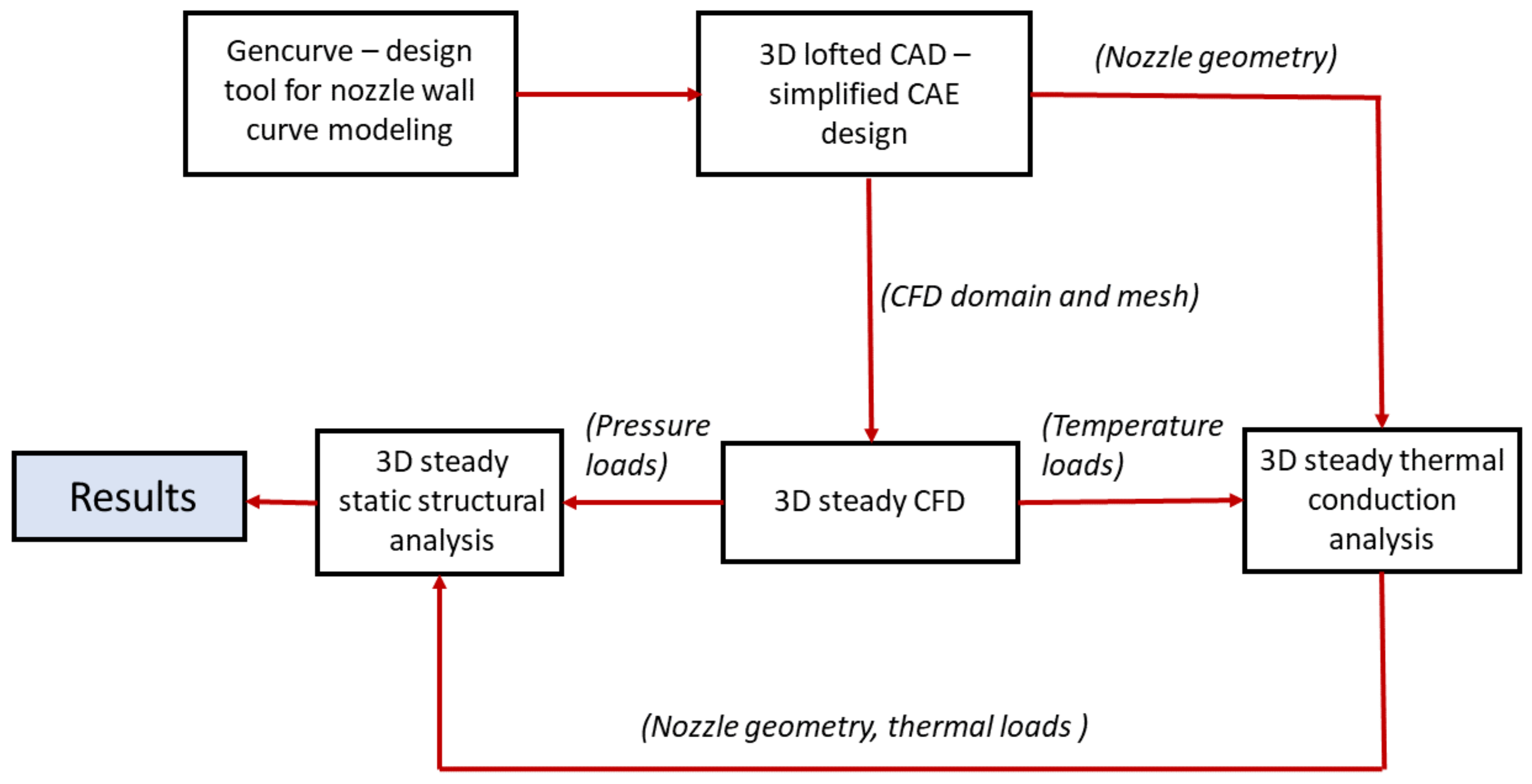
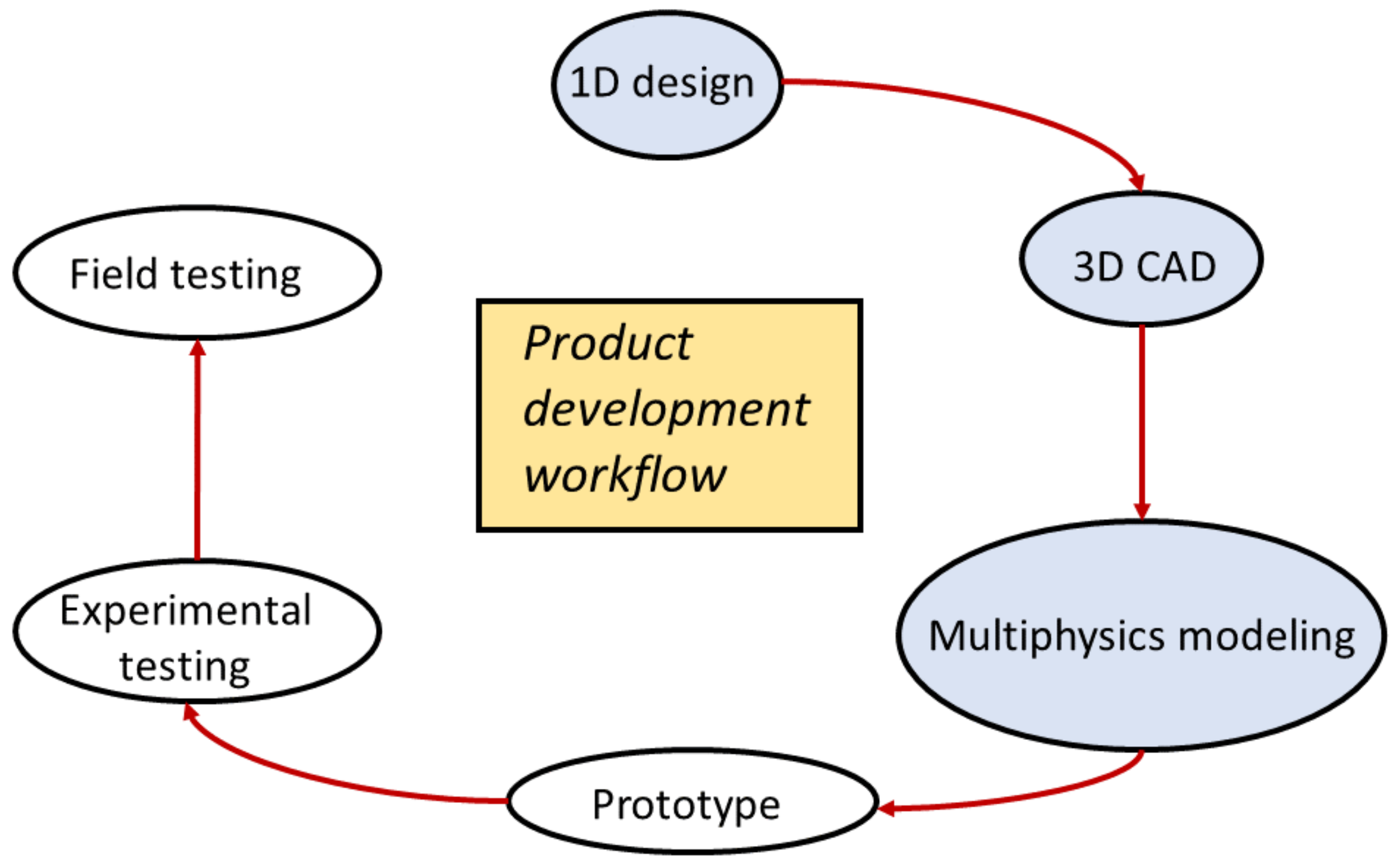
The existing design is improved using 1D to 3D design analysis, where FTSI modeling gives an insight into the structural integrity at off-design conditions. Although a supersonic rectangular nozzle is investigated, this approach can be applied in general to demonstrate the benefits of FTSI in the initial stages of product development, as shown in Figure 12.
4. Discussion
Considering the time, cost and energy associated with experimental testing, it is crucial to manufacture a design which can withstand pressure and temperature loads at various operating conditions in rectangular supersonic nozzles. This work highlights that the accuracy of every step matters a lot since the structural deformation is affected by the shock loads which are affected by the boundary layer which makes the y+ essential. The choice of turbulence model plays a key role in capturing the shock cell amplitude, as can be seen from the current validation. A detailed scrutiny with compressibility correction will reduce the error margin, however, for the objective of showing FTSI, the current validation is sufficient to move ahead. An effort is made to connect the flow physics with the structural integrity, which has enormous potential as a prelude to building a prototype. Exploiting the advancements in simulation technology is essential to showing the proposed design is feasible for real-world operation. Current diagnosis demonstrates analysis for the improved design as a precursor to prototyping. Hence, one-way steady-state FTSI is performed, which serves as preliminary investigation during steady-state operation. However, evaluating the impact of structural deformation on boundary layer flow during unsteady operation is crucial for SBLI with tight coupling, and will be addressed in the next phase of this research. In addition to this, fatigue induced due to the number of operating cycles will also be studied in the future. Furthermore, side plate thickness and nozzle wall thickness will be optimized to reduce the overall weight and material costs.
5. Conclusions
The novelty of this work lies in the fluid-thermal-structural interaction simulations, which are, for the first time, performed on rectangular supersonic nozzles. This work also connects the structural deformation and boundary layer flow which is a novel approach. An existing design is improved using an in-house Python based design tool called Gencurve, which demonstrates the benefits of the slope-matching technique for generating nozzle wall curves. Aerodynamic performance improvements in terms of discharge coefficient and total pressure recovery coefficient are achieved due to the reduced in-nozzle shocks. Although the current RANS modeling (k-omega SST) increases the amplitude of the first shock cell, the amplitude is still in the acceptable range, although it is not tight enough and gives a better approximation of the overall velocity decay than other turbulence models. The multi-physics modeling approach is used to evaluate the feasibility of the existing and improved design. This work shows that FTSI becomes essential during the initial design phase of supersonic rectangular converging/diverging nozzles, due to the elevated heat transfer in supersonic flow. Observed mild throat shocks do not affect boundary layer flow in the existing design. Hence, the impact of SBLI on the existing nozzle is not as severe because the structural deformation is far less than the boundary layer thickness. The improved design does not fail at highest NPR, making it safer at low NPRs. A general 1D to 3D design analysis approach is demonstrated through the rectangular nozzle design case, which highlights the significance of FTSI and shows that it can also be used in any other product development cycle.
Acknowledgments
This research is part of Master’s thesis and would not have been possible without guidance from Kiran Siddappaji and Shaaban Abdallah. Thanks to Florian Baier for sharing the experimental data which was used to validate the CFD results. This work was never funded.
Author Contributions
Kalyani Bhide worked on this topic as part of her Master’s thesis and is the main contributor creating the geometry, work flow, performing simulations, gathering results, improving the process and explaining the flow physics. Kiran Siddappaji as a mentor discussing the general outline including flow physics, technical expertise, best practices in multidisciplinary simulations and initiating the topic with the main author. Shaaban Abdallah as the advisor providing computational resources for the numerical simulations.
Conflicts of Interest
The authors declare no conflicts of interest.
Abbreviations
| CAD | Computer-Aided Design |
| CAE | Computer-Aided Engineering |
| CFD | Computational Fluid Dynamics |
| FTSI | Fluid Thermal Structural Interaction |
| LES | Large Eddy Simulation |
| NPR | Nozzle Pressure Ratio |
| RANS | Reynolds Averaged Navier Stokes |
| SBLI | Shock wave Boundary Layer Interaction |
| SST | Shear Stress Transport |
| TR | Temperature Ratio |
| y+ | Wall y plus |
Nomenclature
| δ | Boundary layer thickness |
| Δ | Structural deformation |
| e | Error |
| De | Nozzle equivalent diameter |
| Mass flow rate | |
| Pa | Pascal |
| Tin | Static temperature at nozzle inlet |
| Tex | Static temperature at nozzle exit |
| Vexp | Experimentally measured velocity |
| Vsim | Numerically calculated velocity |
| xin | Nozzle wall X coordinate at inlet |
| xex | Nozzle wall X coordinate at exit |
| xth | Nozzle wall X coordinate at throat |
| yin | Nozzle wall Y coordinate at inlet |
| yex | Nozzle wall Y coordinate at exit |
| yth | Nozzle wall Y coordinate at throat |
| θin | Nozzle wall inlet angle with X axis |
| θex | Nozzle wall exit angle with X axis |
References
- Baier, F.; Mora, P.; Gutmark, E.; Kailasanath, K. Flow measurements from a supersonic rectangular nozzle exhausting over a flat surface. In Proceedings of the 55th AIAA Aerospace Sciences Meeting, Grapevine, TX, USA, 9–13 January 2017. [Google Scholar]
- Viswanath, K.; Johnson, R.; Corrigan, A.; Kailasanath, K.; Mora, P.; Baier, F.; Gutmark, E. Noise characteristics of a rectangular vs circular nozzle for ideally expanded jet flow. In Proceedings of the 54th AIAA Aerospace Sciences Meeting, San Diego, CA, USA, 4–8 January 2016. [Google Scholar]
- Munday, D.; Gutmark, E.; Liu, J.; Kailasanath, K. Flow structure of supersonic jets from conical cd nozzles. In Proceedings of the 39th AIAA Fluid Dynamics Conference, San Antonio, TX, USA, 22–25 June 2009. [Google Scholar]
- Heeb, N.; Mora, P.; Gutmark, E.; Kailasanath, K. Investigation of the noise from a rectangular supersonic jet. In Proceedings of the 19th AIAA/CEAS Aeroacoustics Conference, Berlin, Germany, 27–29 May 2013. [Google Scholar]
- Cuppoletti, D.; Gutmark, E.; Hafsteinsson, H.; Eriksson, L.-E. The role of nozzle contour on supersonic jet thrust and acoustics. AIAA J. 2014, 52, 2594–2614. [Google Scholar] [CrossRef]
- Dippold, V., III. Design and analyses of high aspect ratio nozzles for distributed propulsion acoustic measurements. In Proceedings of the 34th AIAA Applied Aerodynamics Conference, Washington, DC, USA, 13–17 June 2016. [Google Scholar]
- Frate, F.; Bridges, J. Extensible rectangular nozzle model system. In Proceedings of the 49th AIAA Aerospace Sciences Meeting including the New Horizons Forum and Aerospace Exposition, Orlando, FL, USA, 4–7 January 2011. [Google Scholar]
- Riley, Z.; McNamara, J. Hypersonic boundary layer stability in the presence of thermos-mechanical surface compliance. In Proceedings of the 53rd AIAA/ASME/ASCE/AHS/ASC Structures, Structural Dynamics and Materials Conference, Honolulu, HI, USA, 23–26 April 2012. [Google Scholar]
- Bhide, K.; Siddappaji, K.; Abdallah, S. A combined effect of wall curvature and aspect ratio on the performance of rectangular supersonic nozzles. In Proceedings of the 6th International Conference on Jets, Wakes and Separated Flows, Cincinnati, OH, USA, 9–12 October 2017. [Google Scholar]
- Geerts, J. Shock Train Boundary Layer Interactions in Rectangular Supersonic Isolators. Ph.D. Thesis, University of Maryland, College Park, MD, USA, 2015. [Google Scholar]
- Kim, S.D.; Song, D.J. Modified shear-stress transport turbulence model for supersonic flows. J. Aircr. 2005, 42, 1118–1125. [Google Scholar] [CrossRef]
- Pironkov, P. Numerical Simulation of Thermal Fluid Structure Interaction. Ph.D. Thesis, Technical University of Darmstadt, Darmstadt, Germany, 2010. [Google Scholar]
- Georgiadis, N.; DeBonis, J. Navier–Stokes analysis methods for turbulent jet flows with application to aircraft exhaust nozzles. Prog. Aerosp. Sci. 2006, 42, 377–418. [Google Scholar] [CrossRef]
- Truemner, J.; Mundt, C. Total Temperature Based Correction of the Turbulence Production in Hot Jets. In Proceedings of the ASME Turbo Expo 2017: Turbomachinery Technical Conference and Exposition, Charlotte, NC, USA, 26–30 June 2017. [Google Scholar]
- Gross, N.; Blaisdell, G.; Lyrintzis, A. Evaluation of turbulence model corrections for supersonic jets using the OVERFLOW code. In Proceedings of the 40th Fluid Dynamics Conference and the Exhibit, Chicago, IL, USA, 28 June–1 July 2010. [Google Scholar]
- Wilcox, D.C. Turbulence Modeling for CFD, 2nd ed.; DCW Industries, Inc.: La Canada, CA, USA, 1994; ISBN 0-9636051-0-0. [Google Scholar]
- Siddappaji, K.; Turner, M.; Merchant, A. General Capability of Parametric 3D Blade Design Tool for Turbomachinery. In Proceedings of the ASME Turbo Expo 2012, Copenhagen, Denmark, 11–15 June 2012. [Google Scholar]
- Using Imported Loads for One-Way FSI. Available online: https://www.sharcnet.ca/Software/Ansys/17.0/enus/help/wb_sim/ds_fluid_structure_interaction_imported.html (accessed on 17 November 2017).
- Solidworks Tutorials. Available online: http://www.solidworks.com/sw/resources/solidworks-tutorials.htm (accessed on 17 November 2017).
- Munday, D. Flow and Acoustics of Jets from Practical Nozzles for High-Performance Military Aircraft. Ph.D. Thesis, University of Cincinnati, Cincinnati, OH, USA, 2010. [Google Scholar]
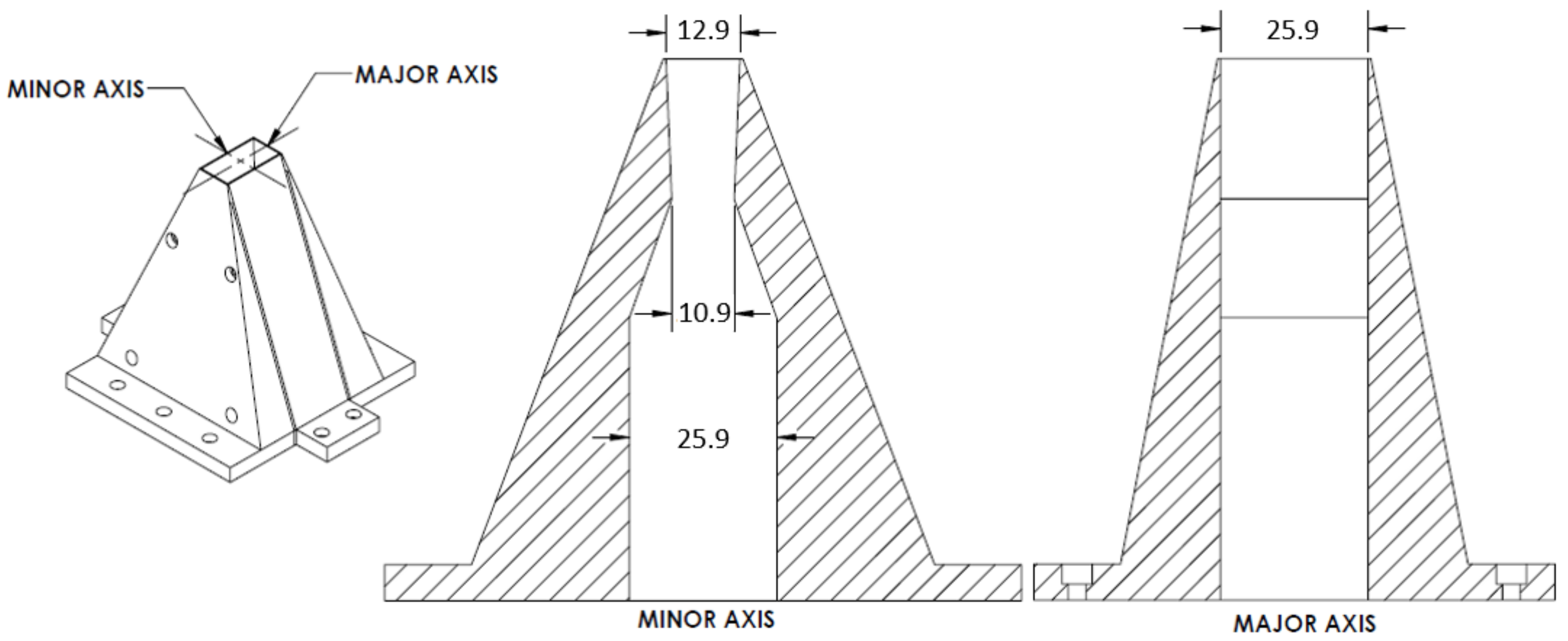
Figure 1.
AR 2 rectangular nozzle geometry (all dimensions are in mm) taken from Viswanath et al. [2].
Figure 1.
AR 2 rectangular nozzle geometry (all dimensions are in mm) taken from Viswanath et al. [2].

Figure 2.
Grid resolution study.
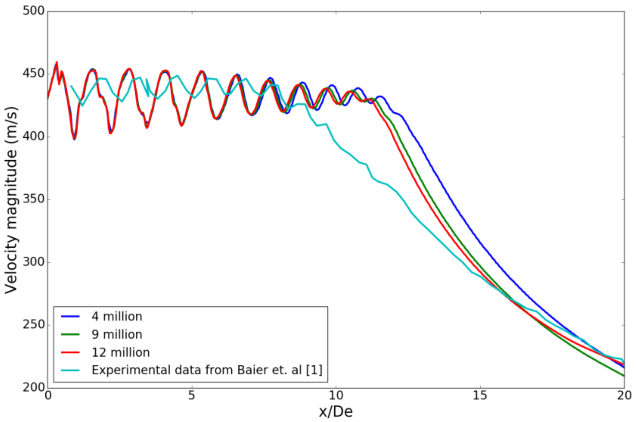
Figure 3.
Turbulence model study.

Figure 4.
Improved nozzle design with contoured walls shown in green.
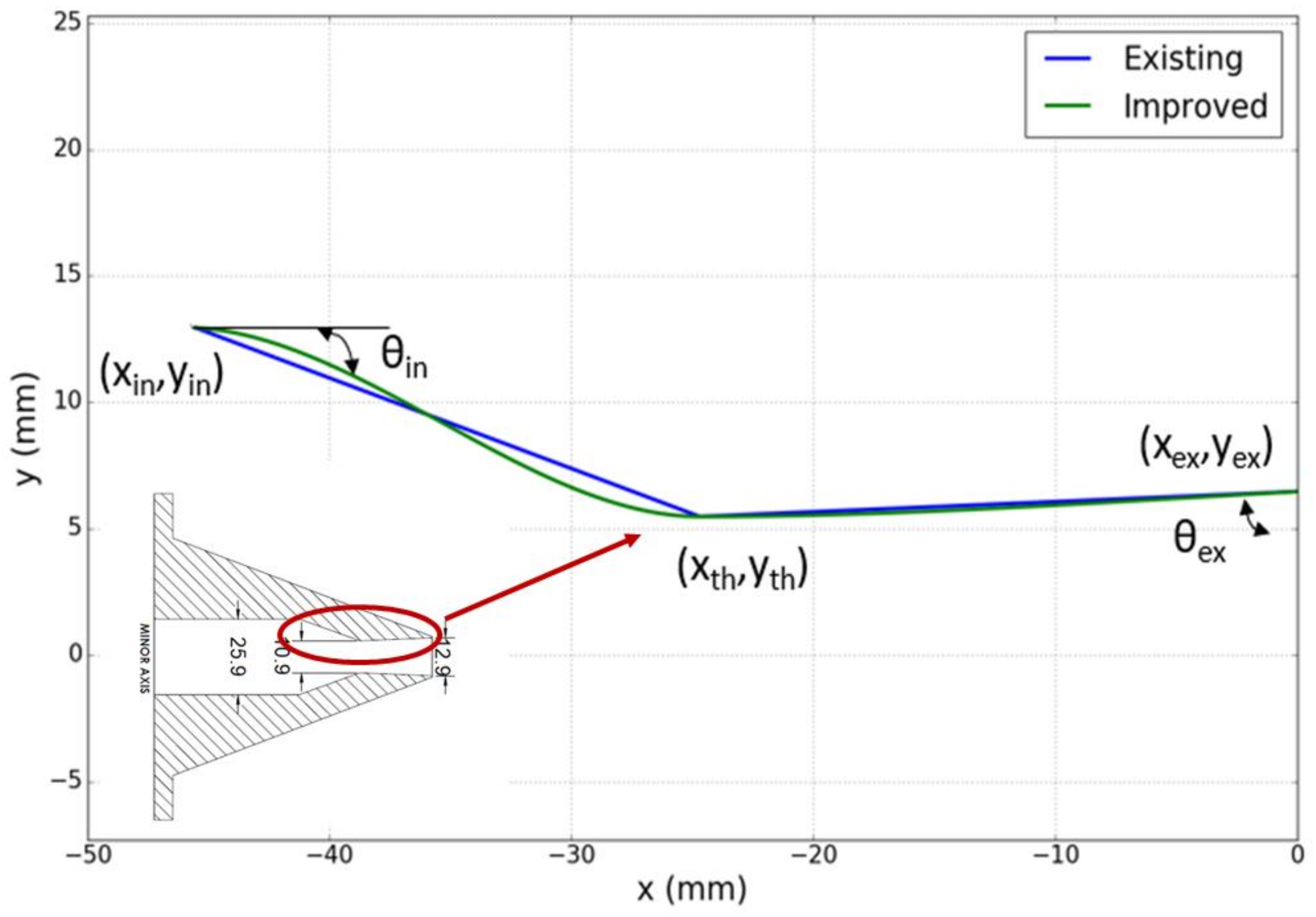
Figure 5.
One-way coupled Fluid–Thermal–Structural Interaction (FTSI) flowchart.

Figure 6.
One-way FTSI methodology with the sequence of steps numbered as seen in the image.
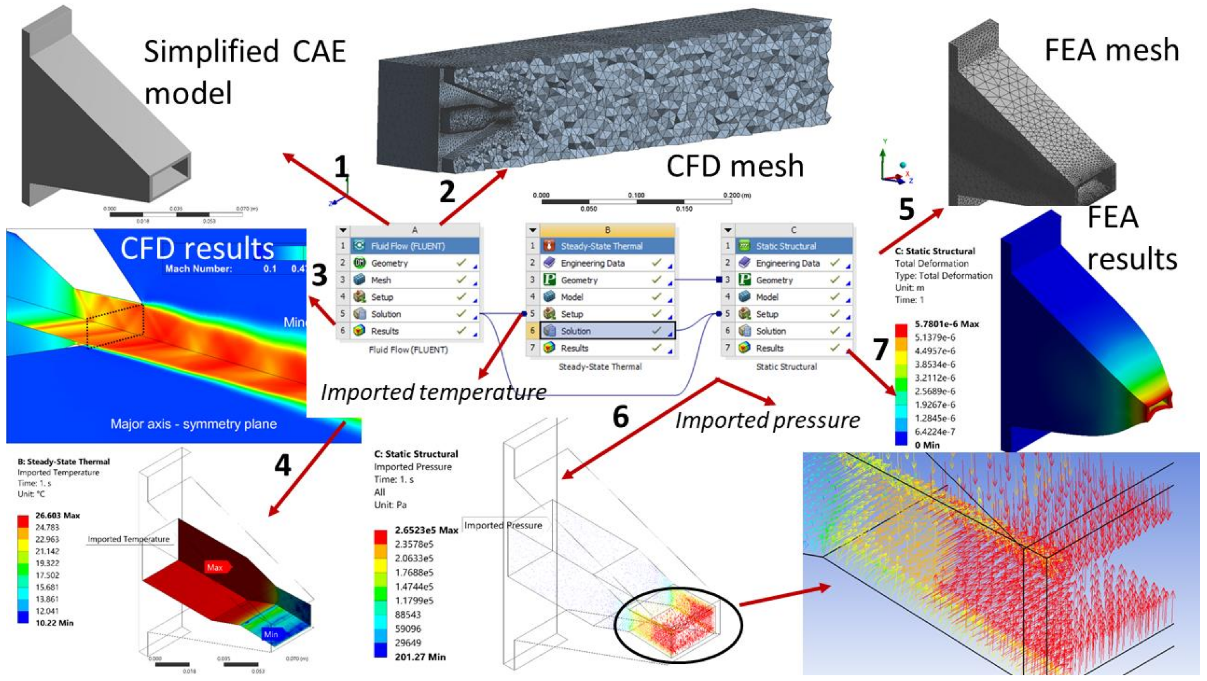
Figure 7.
Mach contours on symmetry planes in existing nozzle shown on a quarter section.
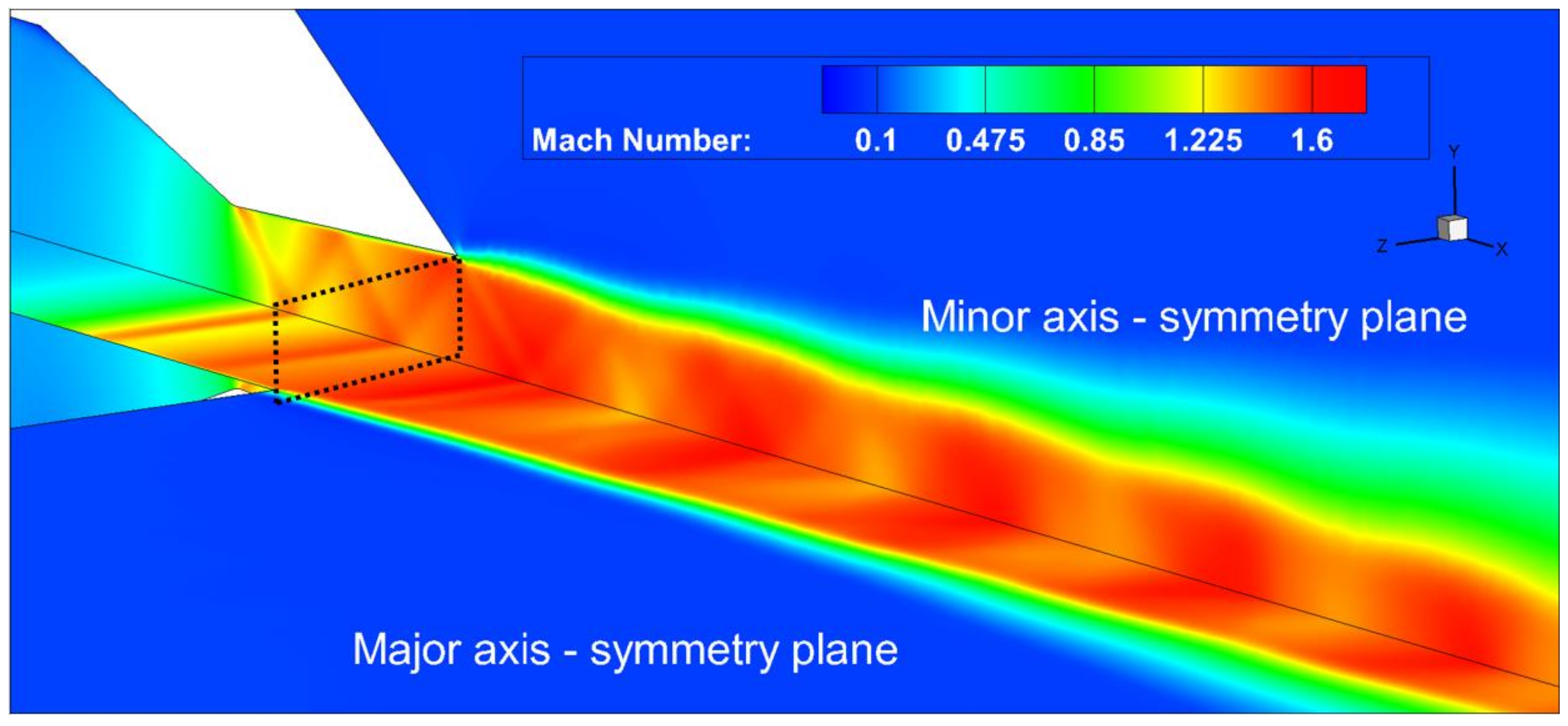
Figure 8.
Wall shear stress on nozzle walls; (a) existing design and (b) improved design.

Figure 9.
Total pressure on nozzle walls; (a) existing design and (b) improved design.
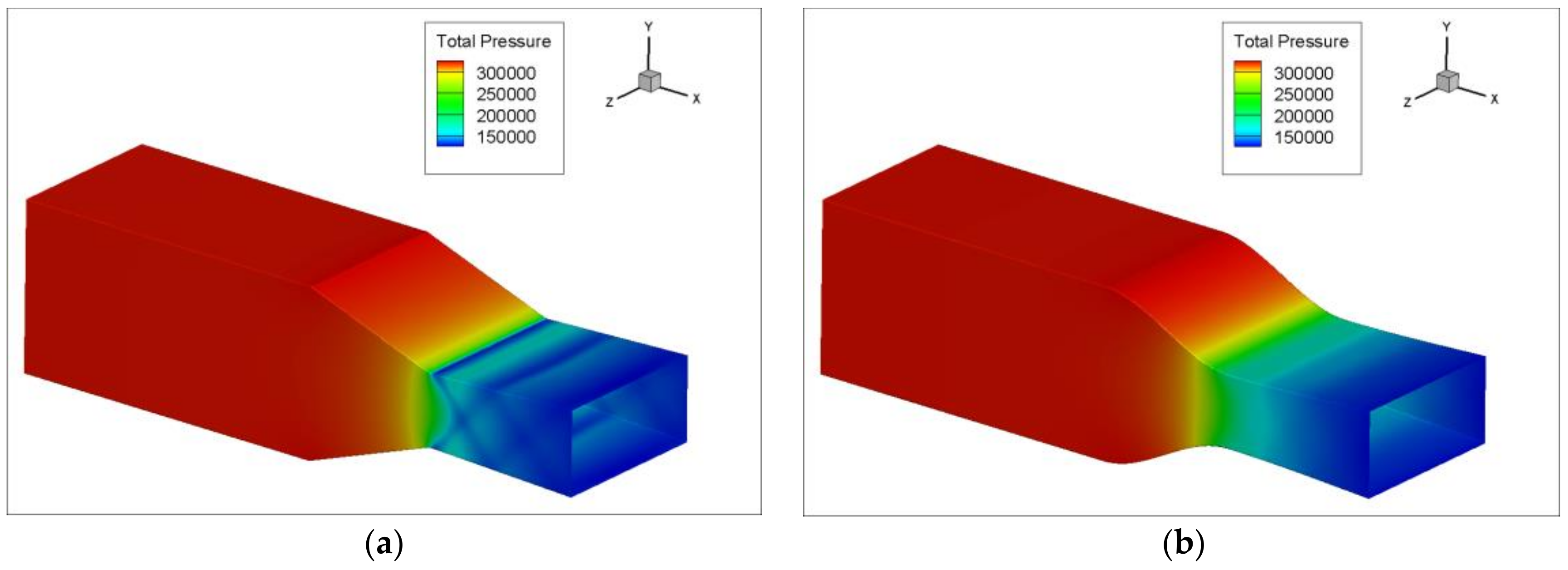
Figure 10.
Equivalent (Von-Mises) stress at NPR 4.5 for improved design.
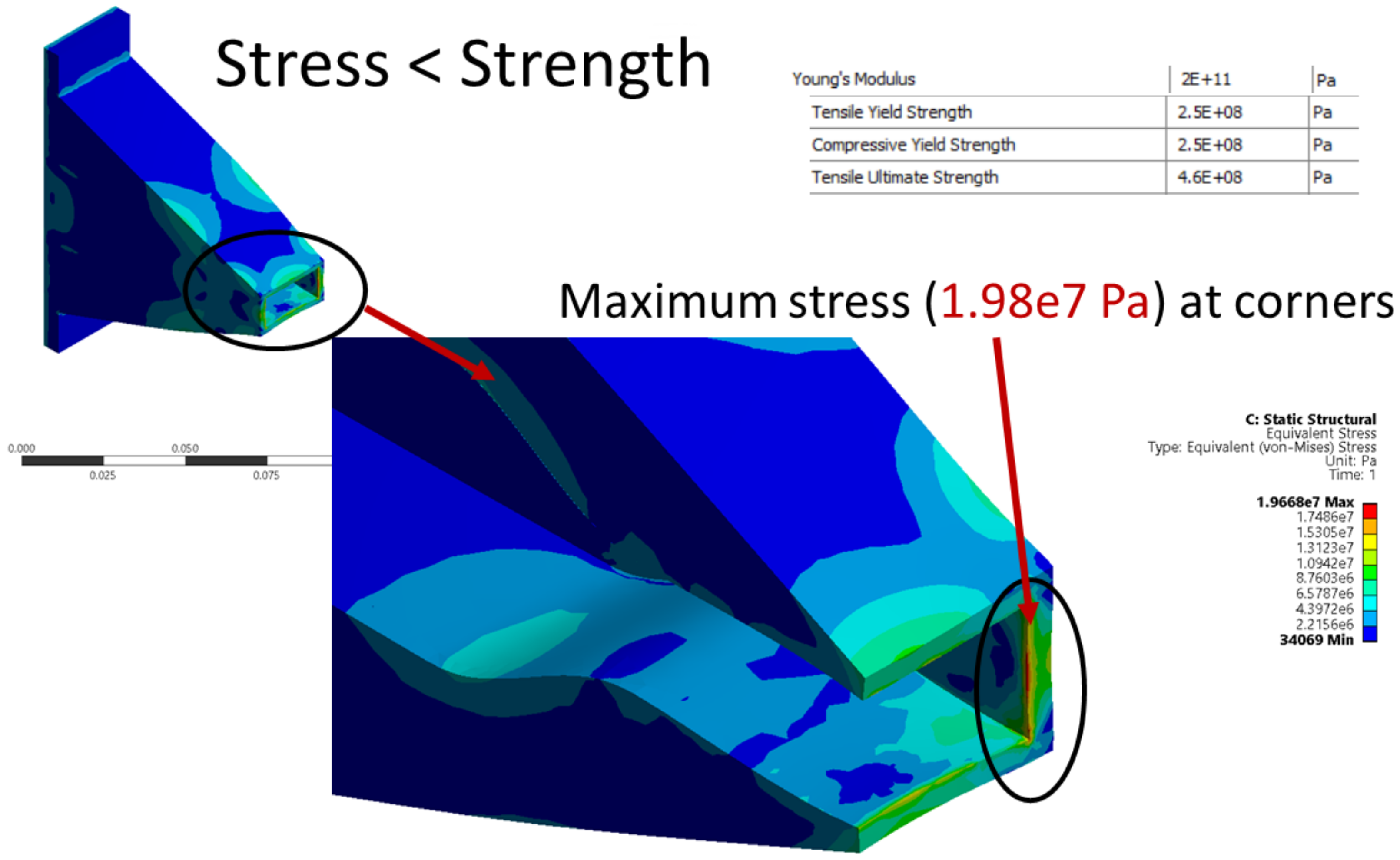
Figure 11.
Total deformation (exaggerated 3× for visualization) and thermal strain in improved design.
Figure 11.
Total deformation (exaggerated 3× for visualization) and thermal strain in improved design.

Figure 12.
Product development workflow, including multi-physics simulations.


Table 1.
Grid details.
| Units | Coarse | Medium | Fine | |
|---|---|---|---|---|
| Cell count | Million | 4.56 | 9.56 | 12 |
| Base size | mm | 50 | 50 | 50 |
| Refinement cell size | mm | 0.5 | 0.35 | 0.3 |
| Throat Pt | (Pa) | 370,884 | 370,887 | 370,805 |
| Mach | 0.8834 | 0.8832 | 0.8859 | |
| (kg/s) | 0.2398 | 0.2397 | 0.2394 | |
| Exit Pt | (Pa) | 363,594 | 363,707 | 363,437 |
| Mach | 1.4857 | 1.4865 | 1.4894 | |
| (kg/s) | 0.241 | 0.241 | 0.2404 |
© 2018 by the authors. Licensee MDPI, Basel, Switzerland. This article is an open access article distributed under the terms and conditions of the Creative Commons Attribution (CC BY) license (http://creativecommons.org/licenses/by/4.0/).
Share and Cite
MDPI and ACS Style
Bhide, K.; Siddappaji, K.; Abdallah, S. Influence of Fluid–Thermal–Structural Interaction on Boundary Layer Flow in Rectangular Supersonic Nozzles. Aerospace 2018, 5, 33. https://doi.org/10.3390/aerospace5020033
AMA Style
Bhide K, Siddappaji K, Abdallah S. Influence of Fluid–Thermal–Structural Interaction on Boundary Layer Flow in Rectangular Supersonic Nozzles. Aerospace. 2018; 5(2):33. https://doi.org/10.3390/aerospace5020033
Chicago/Turabian StyleBhide, Kalyani, Kiran Siddappaji, and Shaaban Abdallah. 2018. "Influence of Fluid–Thermal–Structural Interaction on Boundary Layer Flow in Rectangular Supersonic Nozzles" Aerospace 5, no. 2: 33. https://doi.org/10.3390/aerospace5020033
Note that from the first issue of 2016, this journal uses article numbers instead of page numbers. See further details here.