Thrust Augmentation by Airframe-Integrated Linear-Spike Nozzle Concept for High-Speed Aircraft

1
Japan Aerospace Exploration Agency, Kakuda, Miyagi 981-1525, Japan
2
Hitachi Solutions East Japan, Ltd., Sendai, Miyagi 980-0014, Japan
*
Author to whom correspondence should be addressed.
†
These authors contributed equally to this work.
Aerospace 2018, 5(1), 19; https://doi.org/10.3390/aerospace5010019
Submission received: 8 December 2017
/
Revised: 2 February 2018
/
Accepted: 6 February 2018
/
Published: 9 February 2018
(This article belongs to the Special Issue Propulsion/Airframe Integration)
Abstract
:The airframe-integrated linear-spike nozzle concept applied to an external nozzle for high-speed aircraft was evaluated with regard to the thrust augmentation capability and the trim balance. The main focus was on the vehicle aftbody. The baseline airframe geometry was first premised to be a hypersonic waverider design. The baseline aftbody case had an external nozzle comprised of a simple divergent nozzle and was hypothetically replaced with linear-spike external nozzle configurations. Performance evaluation was mainly conducted by considering the nozzle thrust generated by the pressure distribution on the external nozzle surface at the aftbody portion calculated by computer simulation at a given cruise condition with zero angle of attack. The thrust performance of the proposed linear-spike external nozzle concept was nearly equivalent to that of the baseline geometry though the wall surface area can be significantly reduced. This is because the design of the proposed concept had a compression wall for the exhaust flow, which resulted in increasing the wall pressure. The configuration with the boattail and the angled inner nozzle exhibited a potential for further improvement in thrust performance. The trim balance evaluation showed that the aerodynamic center location appeared as acceptable. Thus, benefits were obtained by employing the airframe-integrated linear-spike external nozzle concept.
1. Introduction
The concept of a long-range hypersonic air transportation system is considered to be highly beneficial for coping with the increasing demands for faster intercontinental air travel and transportation. For example, with respect to an intercontinental travel duration such as between Tokyo and Washington, D.C., a commercial airliner takes approximately 12 h for the cruise phase at an approximate cruise flight speed of Mach 0.85. If the cruise flight speed can be increased, for example, to Mach 5, the flight duration could potentially be reduced to approximately 2 to 3 h. This reduction in flight duration is substantial and would have a significant impact on the industry as well as the air travel market. Over the flight envelope which involves a wide range of altitudes and distances in dense atmosphere after taking off horizontally from the ground, the cruise phase dominates the overall travel time. A scramjet is favorable as the primary engine for a hypersonic aircraft at the cruise phase accounting for the cycle efficiency, thus increasing propulsion efficiency. The airframe shape would be a waverider design, considering the hypersonic flight operations to minimize wave drag [1,2,3,4,5,6,7]. The airframe and the propulsion system of a hypersonic aircraft that has a waverider shape equipped with a scramjet engine must be designed together, as parts of the airframe will be parts of the engine [1].
Numerous concerns and technical challenges still remain for the realization of practical and sustainable hypersonic air transportation systems such as supersonic to hypersonic cruise and propulsion efficiencies [1], economic impacts regarding fuel consumption efficiency, and environmental concerns such as emissions and noise levels. One of the key technologies to resolve these concerns is an advanced airframe-integrated propulsive nozzle system. The propulsive nozzle plays an important role in the entire propulsion system; the nozzle translates the combustion energy gained in the combustor to the thrust that moves vehicle forward at all flight conditions including on-design and off-design conditions. Development of the airframe-integrated propulsive nozzle system is highly recommended to improve the hypersonic cruise and propulsion efficiencies as well as reducing noise levels. Therefore, designing such a novel airframe-propulsion integration, namely, airframe-integrated advanced nozzle configuration as part of the airframe aftbody is considered critical [8].
To date, many insights on the aftbody configuration for hypersonic aircraft have been provided through numerous studies on the scramjet nozzle [4,9,10]. Those studies mainly focused on an open-style external nozzle configuration comprised of a straight ramp as opposed to a simple divergent duct nozzle [3]. The open-style external nozzle appears as the airframe aftbody that causes the primary engine exhaust flow to flow along the airframe surface. With an asymmetric straight ramp external nozzle [9], interactions between the simulated engine exhaust flow and the hypersonic external flow were investigated and showed that the role of intercepting shock formed between those two kinds of flows on determining the ramp surface pressure. Mitani et al. [10] conducted a large-scale combustion test with the aid of computational simulation on the straight ramp external nozzle, and showed that the lift thrust was generated by the external nozzle as well as showing positive net thrust generation. Thus, many insights into employing the straight ramp external nozzle have been obtained. In addition to the straight ramp configuration, Takahashi [8,11] proposed a concept of an airframe-propulsion integration employing a linear aerospike nozzle, namely an airframe-integrated linear aerospike propulsion system [8,11], in order to gain more thrust force from the external nozzle portion. The linear aerospike nozzle configuration can also address the concerns of increasing the propulsion efficiency and the airframe integration and potentially noise reduction.
The linear aerospike nozzle concept has the altitude-compensating features [12,13,14,15] that enable maintaining near-optimal thrust performance at any flight altitude, unlike a conventional bell-shaped nozzle, which reaches maximum performance at only one specific altitude (i.e., the design altitude). This is why the variable geometry nozzle has been employed with the bell-shaped nozzle for existing practical high-speed aircraft. The linear aerospike nozzle can adjust the exhaust flow expansion automatically to the ambient pressure. Additionally, a clustered linear aerospike nozzle concept is beneficial when considering the operational needs of the aircraft such as the attitude control or thrust vectoring [16,17]. Furthermore, the use of an aerospike nozzle facilitates efficient utilization of the entire back area of a rectangular vehicle body (e.g., waverider) to minimize the aftbody base drag. Another advantage of the aerospike nozzle is its low noise generation as has been demonstrated in aircraft applications using a plug nozzle [18,19].
Many insights into the aerospike nozzle have been provided by numerous studies involving ground tests [15,20], numerical simulations [21,22,23], conceptual studies [11,12], and flight tests as part of the Linear Aerospike SR-71 experiment, which was part of the X-33 program [24,25] with regard to freestream effects [14,26,27,28,29,30]. Additionally, the mechanism of open/closed wake conditions [31], clustering effects [32] and side wall effects [33] on the flowfield characteristics, skin friction features on the spike surface [34], and structural and heat loads [35] have been investigated. Among these numerous studies, Takahashi et al. [29,30] demonstrated that thrust performance can be significantly improved even at off-design in-flight conditions under the presence of external flow with a boattail-equipped aftbody configuration integrated into the airframe. This insight is particularly important because the flight performance was anticipated to decrease under transonic flight conditions [26] and off-design flight conditions [36] because of the locally decreased flow and static pressure acting on the airframe and nozzle surfaces. Although a large boattail angle, which appears right upstream of the primary engine nozzle exit, may lead to pressure decrease on its surface and thus generate aerodynamic drag, utilizing the freestream effect may be still beneficial for increasing thrust by automatically adjusting flow expansion to the change of atmospheric air [8,11]. The key physics on the thrust enhancement by the employment of the aerospike nozzle as the external nozzle is that the nozzle wall acts as a compression wall for the exhaust flow and the slip surface forming between the exhaust flow and the external flow determines the wall surface pressure.
While those important insights for thrust improvement by the employment of the aerospike nozzle with the boattail were obtained, this configuration involves complex design features such as the boattail inclination angle, which results in inclining the primary thrust direction. A simpler installation of an external nozzle through a minor modification of the baseline design should be considered. In view of simpler installation of the external nozzle to the airframe, a linear-spike nozzle configuration which possesses a compression wall feature without having the boattail should also be evaluated. In this regard, it is important to evaluate the benefit of employing the linear-spike nozzle configuration as an alteration of the baseline configuration of a simple divergent duct nozzle of a waverider. To this end, it is vital to demonstrate the hypersonic cruise and propulsion efficiencies as well as the flight attitude characteristics by evaluating an airframe-integrated linear-spike propulsion system in its vehicle integration feasibility designed for hypersonic air transportation systems.
The major goal of this study was to evaluate the feasibility of the proposed airframe-integrated linear-spike propulsion concepts which are applied to the aftbody portion of the hypersonic baseline aircraft geometry in regards to thrust augmentation capability and trim balance. While previous studies [8,29,30] emphasized the importance of the boattail portion which appeared right upstream of the primary thruster, this study evaluated no boattail configuration for a contoured linear-spike nozzle to cope with the dual-mode ramjet flowpath in addition to the baseline case. An aerospike-type configuration with the boattail was also compared. The performance evaluation was based on the pressure distribution on the external nozzle obtained by computational work. The computational code was validated by comparing the spike surface pressure to that obtained by corresponding experiments and the quasi-one-dimensional analytical model established in previous studies [8,29,30], which predicted thrust values for each thrust component under in-flight conditions.
2. Baseline Design of Aircraft and Airframe-Integrated Aerospike Propulsion System
2.1. Baseline Airframe Configuration
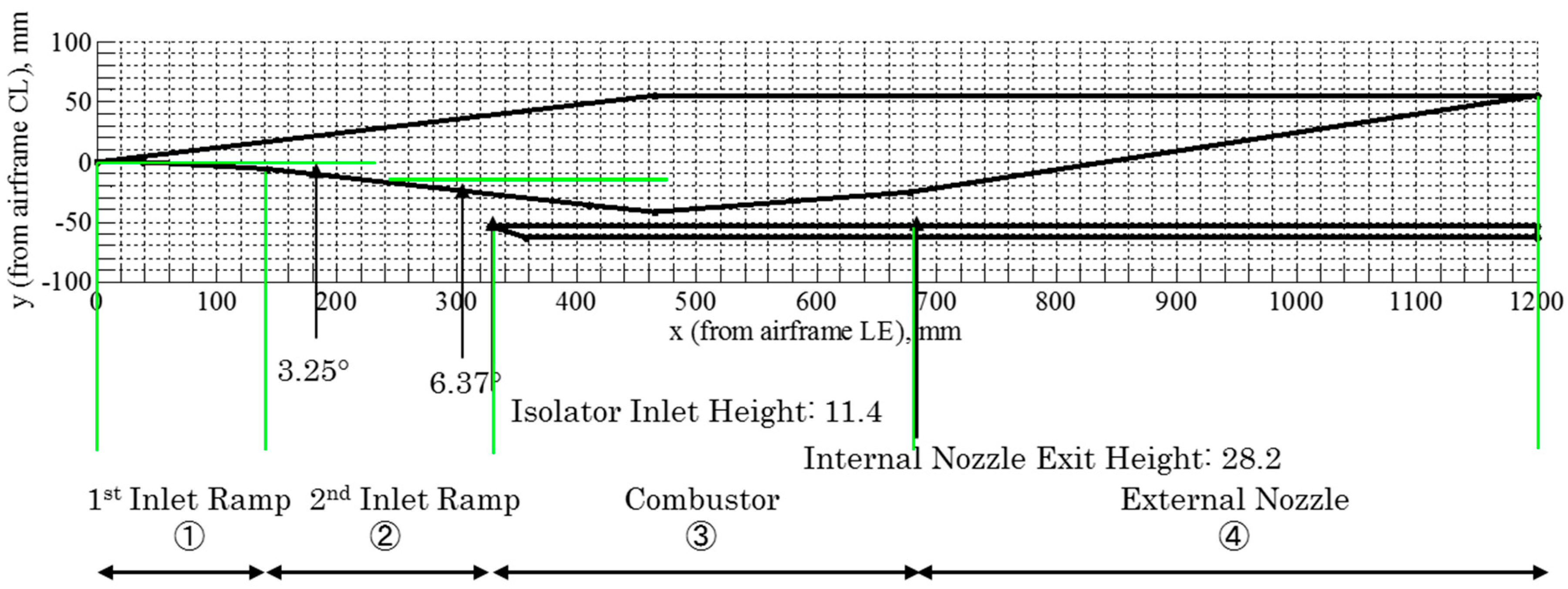
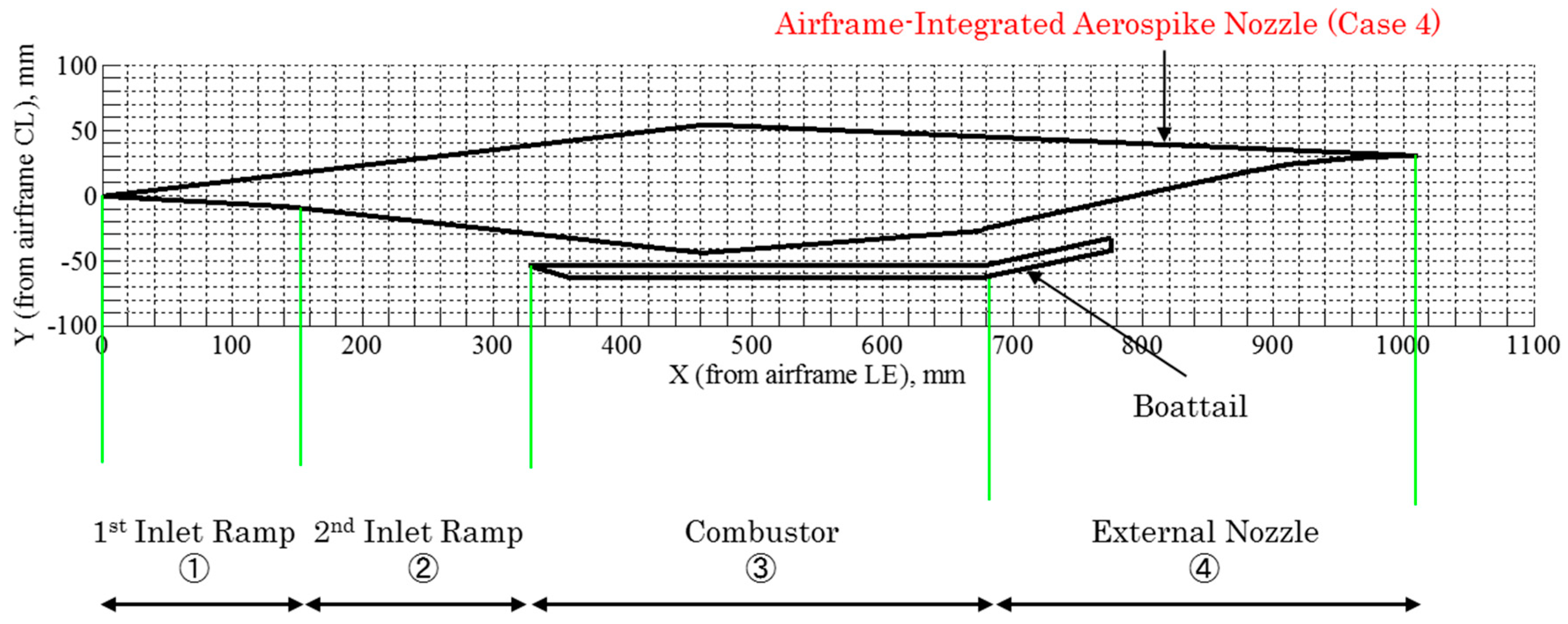
Figure 1 illustrates the center cut of the vehicle body for the baseline case, in which a turbine-based combined cycle (TBCC) airbreathing propulsion system is considered for the primary thruster under hypersonic flight conditions. Only the center cut of the two-dimensional fuselage is considered. The overall geometry is similar to a one-quarter sub-scaled model of the X-51A waverider [3]. Detailed internal geometry was slightly modified for the premised design flight condition. The airframe is comprised of the first inlet ramp, second inlet ramp, combustor, and external nozzle sections. Each section is numbered from 1 through 4 as shown in Figure 1. The double-inlet ramp had angles which were preset at 3.25° and 6.37°, respectively. The second leading edge oblique shock generated from the second inlet ramp was designed to be swallowed into the primary flowpath at the design cruise condition. The flowpath for the primary engine was considered to be a single flow path by assuming that the primary propulsion system is a TBCC engine [37,38,39] that switches the primary engine with turbojet from take-off to approximately Mach 3.0 flight and then with ramjet to dual-mode ramjet and scramjet above flight Mach number of 3.0. The isolator inlet height was 11.4 mm, and the internal nozzle exit height was 28.2 mm. The internal nozzle was the downstream part of the divergent combustor duct. The overall airframe length for the baseline case was 1200 mm, and the overall center cut geometry is presented in Figure 1. The aftbody portion, which had the length of 521.8 mm (starting at x = 672.8 mm), will be modified to install the airframe-integrated linear-spike external nozzle which will be described in detail later. In this configuration, the external nozzle portion is a simple divergent duct. The Mach number at the entrance of the external nozzle, which is equivalent to the exit of the diverging duct of the primary engine, was 3.5. The exit pressure at the external nozzle becomes approximately 7.0. The nozzle exhaust flow would become approximately the optimal expansion condition at the cruise flight condition, which will be described in detail later. This baseline configuration is denoted as Case 1.
2.2. Premised Flight Conditions
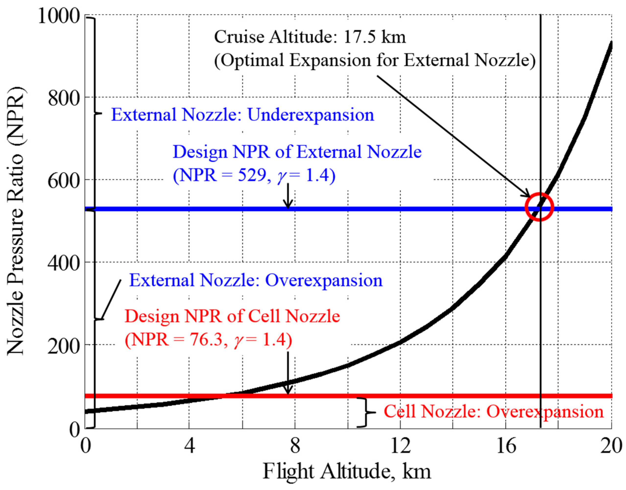
Figure 2 shows the flight conditions simulated in this study. The flight conditions were determined by using the nozzle pressure ratio (NPR), P0j/Pa, which was defined as the pressure ratio between the primary nozzle (or cell nozzle) total pressure (i.e., total pressure in the combustor, P0j) and the environmental pressure (Pa). The NPR identified the jet expansion conditions and simulated the flight altitude conditions. A higher flight altitude condition corresponded to a larger NPR condition by assuming a constant total pressure of the combustor (P0j) with varying environmental pressures (Pa). The designed NPR of the cell nozzle that corresponded to its optimal expansion condition was 76.3. Note that the specific heat ratio (γ) used for the cell nozzle exhaust gas was 1.4 in this study. The flow structure of the cell nozzle exhaust flow formed downstream of the cell nozzle exit changed according to a given NPR condition. The relationship between the flow structure and NPR range is also summarized in Figure 2. The flow expansion condition inside the cell nozzle was obtained by using the same criterion presented in Takahashi [8]. The optimal expansion condition for the spike nozzle with the parameters described here is 529, which had the exit Mach number of 5.0 at the end of the airframe-integrated external nozzle. The simulated cruise flight altitude was premised to be 17.5 km above sea level where the atmospheric pressure is approximately 8.0 kPa. Note that this study focused on the cruise condition where the nozzle operation condition was at the on-design condition, and off-design conditions were not considered, though some thrust improvement would be expected owing to the positive freestream effect at off-design conditions [8]. The atmospheric pressure was calculated based on the U.S. Standard Atmosphere [40]. The altitude range used in this study was the stratosphere where the atmospheric temperature appears constant at 216.6 K. Hence, the acoustic velocity is constant in the stratosphere flight range. The cruise flight was assumed to be a steady flight where the angle-of-attack was 0°.
The total pressure of the combustor, which corresponds to the total pressure of the cell nozzle, was fixed at 4.0 MPa. This is because the existing turbojet engines [41,42] may have an overall pressure ratio of approximately 40 [41,42], thus making the total pressure of the combustor approximately 4.0 MPa. Table 1 summarizes conditions along with other parameters for the engine exhaust flow. The exhaust flow Mach number (Mj) was preset at 3.5. Therefore, the external nozzle accelerates the vehicle up to the cruise Mach number. The cruise Mach number was chosen to be 5.0 as mentioned before. For this cruise condition, the leading-edge oblique shock angle is approximately 12.7°, and therefore the shock wave stays outside of the under-body cowl of the airframe engine inlet.
2.3. Design of Airframe-Integrated External Nozzle (Aftbody-Portion)
The aftbody, which is the external nozzle portion presented in Figure 1 for the baseline configuration, was replaced with the linear-spike nozzle as an airframe-integrated external nozzle. This replacement was made to evaluate the effectiveness of an integration of the proposed nozzle configuration in thrust improvement compared to the simple divergent duct nozzle.
As a comparison to the baseline of the simple divergent duct nozzle and the linear-spike nozzle configurations, first, a simple straight ramp external nozzle, which does not have the lower body-side cowl and thus is the configuration with an open-style external nozzle, was evaluated. This configuration is a simple straight ramp external nozzle that had the same length and height as those of the baseline case and is denoted as Case 2. Note that the nozzle feature of this configuration is an expansion wall for the entire surface.
Because the external nozzle following to the cell nozzle exit (i.e., exit of the primary engine duct) appears as an expansion wall for the exhaust flow, the maximum initial inclination angle of the external nozzle wall should be clearly addressed so that the exhaust flow is not separated from the wall. To this end, a simple separation criterion [43] was used. The criterion was empirically established by collecting numerous nozzle separation data and is expressed as Equation (1):
where Pexternal_nozzle and Mexternal_nozzle are the static pressure and the Mach number of the exhaust flow right after the cell nozzle exit, respectively. The ambient pressure was premised to be 8 kPa as mentioned above. Other parameters are also described in the previous section. Pexternal_nozzle and Mexternal_nozzle were calculated isentropically using the exhaust flow parameters described in Table 2. Figure 3 plots the pressure ratio defined by Equation (1) against the initial inclination angle of the external nozzle wall (θini). The region above the cross-point of the left-hand side and the right-hand side of Equation (1), respectively, is where no flow separation is involved. For the conditions considered in this study, the flow separation is not involved up to the initial inclination angle of approximately 30°. In this regard, there is no flow separation on the external nozzle wall for the baseline case and Case 2 where the initial inclination angle of the external nozzle wall appears as 8.7°.
2.4. Designed Airframe-Integrated Linear-Spike External Nozzle
As mentioned in the introduction, a nozzle configuration which possesses a compression wall feature would be beneficial for thrust improvement. Therefore, a linear-spike nozzle configuration that possesses a compression wall feature is considered. The design method of the linear-spike external nozzle with a compression wall as an airframe-integrated external nozzle is described in this section. The linear-spike nozzle section is comprised of a non-clustered two-dimensional cell nozzle with a designed Mach number (Mj) of 3.5. The nozzle section is then followed by a straight planar section and a contoured spike section. The straight section appears because the design Mach number of the cell nozzle is different from unity. Therefore, the Mach wave emanating from the cell nozzle lip (i.e., airframe-bottom cowl side) impinges on the external-nozzle wall. Behind the Mach wave impingement point (the end point of the straight section), the wall contour was designed using the method of characteristics with given parameters and exhaust flow properties to eliminate reflected expansion waves on the spike surface. Therefore, the contour section acts as a compression wall for the exhaust flow. In this study, the full spike length (i.e., no truncation of the spike) is considered, and therefore no base region behind the linear-spike external nozzle appears. The height of the projected airframe rear area was 117.9 mm for the baseline case; the height could have a different value depending on the designed spike geometry. Note that the width of the vehicle is not considered in this study because only the center-cut plane is considered. The specific heat ratio (γj) of the cell nozzle exhaust gas (i.e., primary engine exhaust gas) was assumed to be 1.4 in this study as described in Table 1.
Figure 4 presents the resultant linear-spike external nozzle geometry with the design criteria that the Mach number at the external nozzle exit at ideal expansion becomes equal to the cruise Mach number (Mach 5.0) and that the external nozzle length is equivalent to that of the baseline case. The length is 468.7 mm and the height is 68.1 mm. The resultant initial inclination angle of the external nozzle wall was 20° here. There is no flow separation expected as described in Figure 3. This configuration is denoted as Case 3 and presented in Figure 4. The baseline case is also presented in Figure 4 for comparison. The major difference between Cases 2 and 3 is the wall feature: Case 2 has only an expansion wall for the entire surface and Case 3 has a compression wall following to the initial expansion wall.
Since the previous studies [8,29,30] showed the benefit of the aerospike configuration equipped with a boattail and its importance to utilize the positive freestream effect for thrust enhancement, the configuration with the boattail is also compared. This configuration is denoted as Case 4. The external nozzle geometry of Case 4 was designed based on the same method and conditions used for Case 3. The difference between Case 4 and other cases is that Case 4 has the boattail portion that appears right upstream of the cell nozzle exit, and therefore the cell nozzle is inclined to the airframe axis at the boattail angle. It should be noted that Case 4 involves more complicated design features compared to Cases 2 and 3 because of its having the boattail. The boattail angle gives the cell nozzle inclination angle to the airframe axis. In this configuration, the boattail angle should be within a limit that the boattail flow does not involve any flow separation on its surface. The separation criteria expressed as Equation (2) was used to evaluate the separation limit of the boattail angle without involving flow separations. The left-hand side is the pressure ratio between the pressure on the boattail and the atmospheric air pressure at the cruise flight condition. Figure 5 presents this pressure ratio plotted against the flight Mach number and for some various boattail angles (θbt). The right-hand side of Equation (2) is also plotted to give the separation limit. The flow Mach number and pressure on the boattail were calculated by use of the isentropic relationship and the oblique shock wave relationships where the shock wave is involved.
The separation limit with regard to the boattail angle was found to be approximately 14° for the flight conditions considered in this study. With some margins for the separation limit, the boattail angle of 12° was considered for Case 4. The resultant airframe-integrated aerospike-type external nozzle configuration with the boattail is presented in Figure 6. The boattail length was preset to be 100 mm. Table 2 summarizes all aforementioned external nozzle configurations presented in this study.
3. Quasi-One-Dimensional Analysis and CFD Simulation
This section describes the simplified thrust performance evaluation based on the quasi-one-dimensional analysis with the aid of computational fluid dynamics (CFD) simulation with an emphasis on the aftbody portion of the center cut of the entire airframe.
3.1. Quasi-One-Dimensional Flowfield and Thrust Analysis
The simplified overall thrust performance prediction model for the propulsion system comprised of the cell nozzle section and the external nozzle section that are presented in Figure 1, Figure 4 and Figure 6 is given by the linear summation of the primary engine thrust, namely cell nozzle thrust (Fcell) and the thrust generated by the external nozzle (Fexternal), and is expressed by Equation (3):
For the baseline case, the overall thrust is expressed in detail by Equation (4). Here, the external nozzle thrust can be incorporated into the cell nozzle thrust since the external nozzle section for this configuration becomes an extended divergent nozzle section of the cell nozzle.
Here, Equation (4) can be decomposed to Equations (5) and (6) for the cell nozzle thrust and the thrust generated by the divergent section, respectively. Equation (5) represents the thrust generated by the primary cell nozzle and will be used commonly for every case. The first and second terms in Equation (5) represent the internal and external thrusts, respectively, from the cell nozzle and the third term is the ram drag. The ram drag was calculated based on the air flow behind the leading-edge oblique shock wave and at the entrance of the isolator inlet. These calculations were implemented based on aerodynamic one-dimensional analysis. The duct and exit geometries of the cell nozzle were considered to be rectangular. The aft portion of the cell nozzle was a diverging duct by accounting for the scramjet engine. Other drag forces such as the inlet spillage drag were not considered in this study because it focuses on the evaluation of the aftbody configuration.
For the proposed case that possesses the propulsion system with the airframe-integrated linear-spike nozzle section during in-flight conditions, the external nozzle thrust expressed by the second term in Equation (3) is expressed in detail by Equation (7). The cell nozzle thrust is expressed by the first term in Equation (3) as well as for Case 1. The external nozzle force was calculated by accounting for the pressure distributions and their directions acting on the airframe and nozzle surface as shown in Figure 7a. This illustration is applied to Cases 2 and 3.
The left-hand side of Equation (7) is the aerodynamic thrust generated by the external nozzle portion. On the right-hand side, the first and second terms are the thrusts generated from the straight and spike sections, respectively. Here, the initial spike contour angle (θini) was considered. As opposed to the previous studies [8,29,30,36], no boattail was equipped right upstream of the cell nozzle exit. The third term is the skin friction drag while the fourth term is the ambient pressure drag. The local contour angle, θlocal, was taken into account when integrating the spike surface pressure (i.e., marching method for thrust integration). The flow deceleration attributable to the leading-edge oblique shock wave was also considered in this equation. The surface pressure distribution which will be the primary thrust component in Equation (7) will be discussed in a later section along with the flowfield feature predicted by CFD calculation.
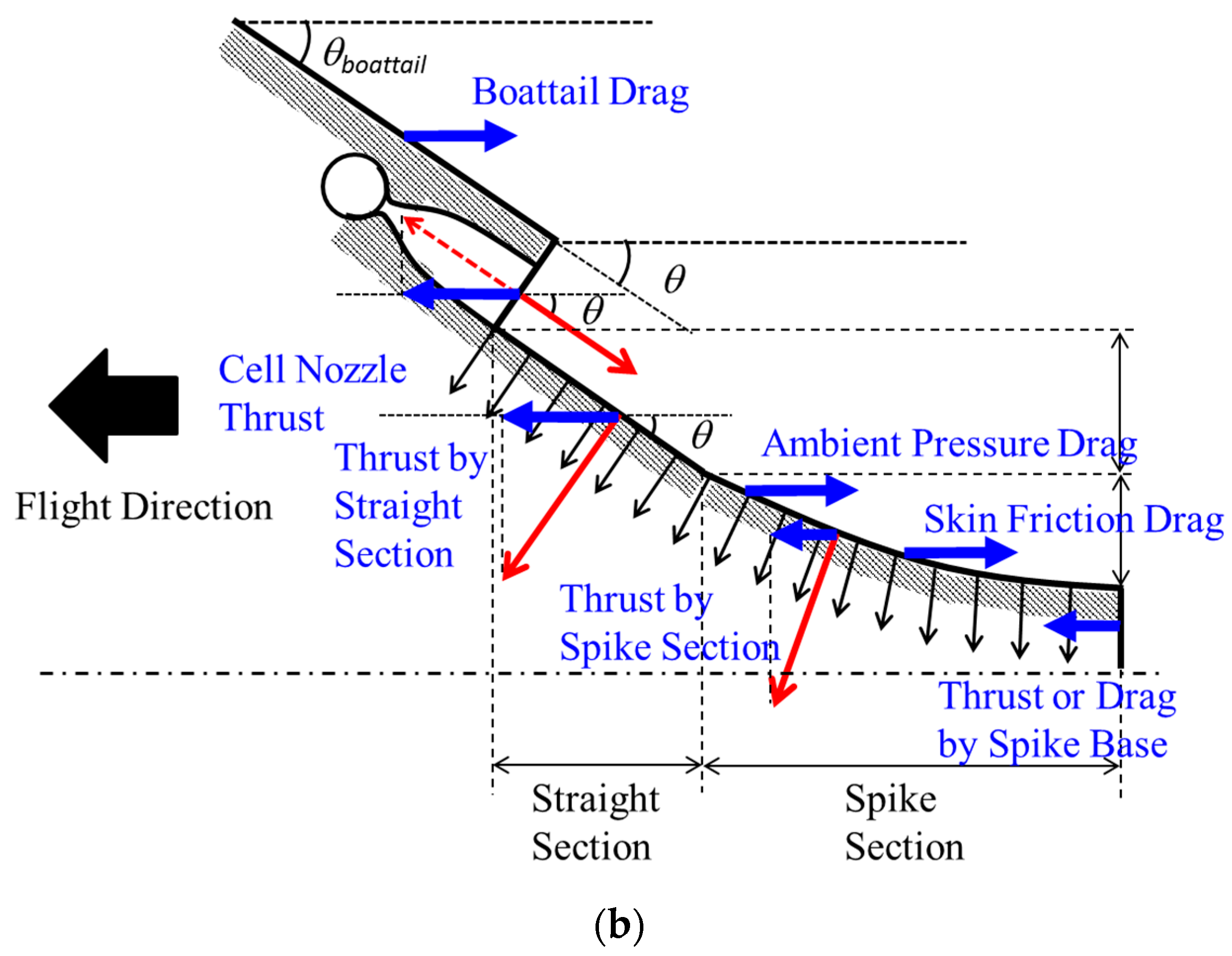
In the case of aerospike-type configuration equipped with the boattail (presented in Figure 6 as Case 4), the thrust generated by the cell nozzle and the thrust generated by the spike nozzle section are expressed as Equations (8) and (9), respectively, by accounting for the boattail angle (θbt) and the additional fifth term meaning the boattail drag in Equation (9). Pressure distributions acting on the surface are described in Figure 7b. θbt emerges as being significant for Case 4 presented in Figure 6 and is eliminated for Cases 1 to 3.
The boattail drag is an important concern to improve the vehicle performance [8,29,30]; the external flow expands on the boattail and thus reduces pressure on the boattail surface; at the same time, this existence of the boattail offers some positive freestream effect on gaining thrust. The boattail drag was calculated from the fifth term in Equation (9) by considering the angle and length of the boattail which were described in the previous section as no flow separation on the boattail was involved.
Wall impingement by oblique shock waves significantly increased skin friction drag, whereas expansion waves negligibly affected skin friction drag [34]. Since no analytical model has been established to accurately predict skin friction values under wall impingement by oblique shock waves, skin friction drag was predicted using the Van Driest II model [44], which is given as Equation (10):
where Mlocal is the Mach number of the flow at the location of interest on the spike surface, and Ta is the static temperature of the flow. Mlocal and Ta were obtained by the computational analysis, the details of which will be given in a later section. The viscosities μa and μw for the freestream and at the wall, respectively, were calculated by the Sutherland viscosity law. The wall temperature Tw was assumed to be 1000 K because the temperature was expected to be close to that of the turbine disk [42]. This model can be applied when no separation or shock waves are involved. Because the effect of shock wave impingement on the wall was not considered in this study, the skin friction was estimated by taking the mean value over the entire spike surface.
3.2. Computational Fluid Dynamics Analysis of Aftbody Flowfields
The flowfield of the airframe aftbody portion with the external nozzle was evaluated by CFD simulation. CFD simulation was mainly used to simulate the flowfield of the aftbody portion. The CFD simulation tool was developed by the Japan Aerospace Exploration Agency at Kakuda Space Center based on commercially available source code: the open source field operation and manipulation (OpenFOAM). OpenFOAM has been gaining a reputation for facilitating flexible customization for the flowfield of interest and offering robust calculation. Some modifications to the source code were made to enable computation for the present flowfield.
Prior to computing the external nozzle flowfield, the computational accuracy was validated by comparing the spike surface pressure distribution with that found by experiment for the same configuration and flow conditions [30]. The flow conditions were the same as those found in the corresponding experiment [30]: gaseous nitrogen cell nozzle flow at the exit Mach number of 3.5 under Mach 2.0 external-flow exposed condition. The NPR was 49.5 and the flowfield was two-dimensional. In the model for this validation study, the cell nozzle exit height was 22 mm, the straight section of the spike nozzle was 77 mm, and the total spike contour length was 196 mm. The spike contour was designed by use of the method of characteristics. A more detailed description on the spike design and the experiment is available in Takahashi et al. [30]. The CFD calculation was carried out for the steady two-dimensional flowfield. The viscous condition was incorporated into the computation. The rhoCentralFoam with the Tadmor scheme was mainly employed to calculate the supersonic flowfield. It should be noted that the boundary layer thickness was observed as approximately 5 mm on the spike surface in the wind tunnel experiment. This indicates that the core flow region was reduced to some extent by the effect of viscosity. This viscosity effect was incorporated into the computational work by the aforementioned scheme.
The computation was implemented progressively by changing the initial conditions and input parameter values via several steps. First, lower values for the flow condition were given as input parameters. For example, 30% of the final desired velocity value was given to the computation. The output flowfield after convergence was used as an initial condition for the next step of the calculation. The flow conditions were slightly increased from those used in the first calculation (e.g., 50% of the desired velocity value). These steps were iterated until the initial conditions and the final output values converged. This progressive method facilitates stable and robust calculation for an extreme environment such as seen in the hypersonic flowfield involving high Mach number and high-pressure flow conditions.
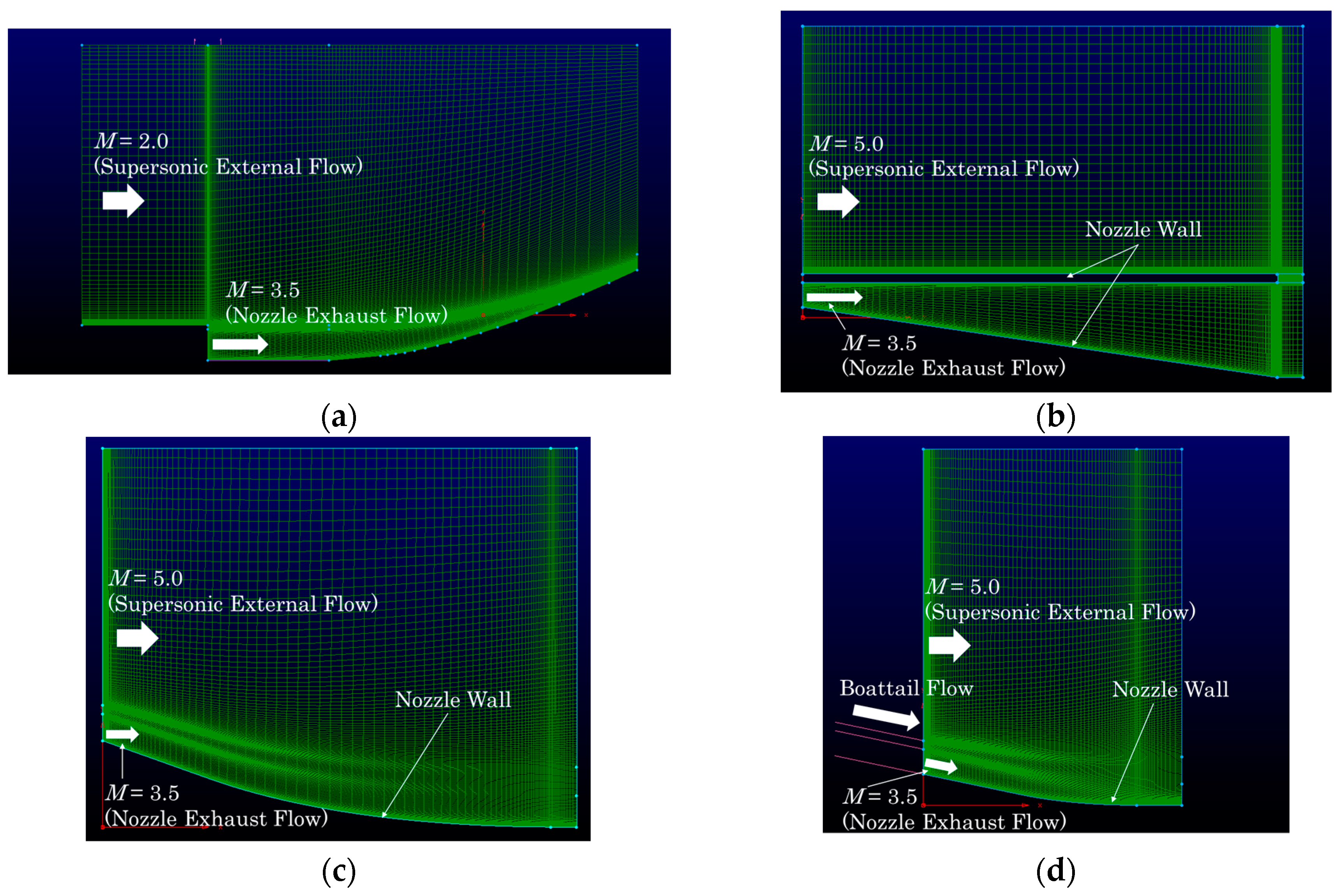
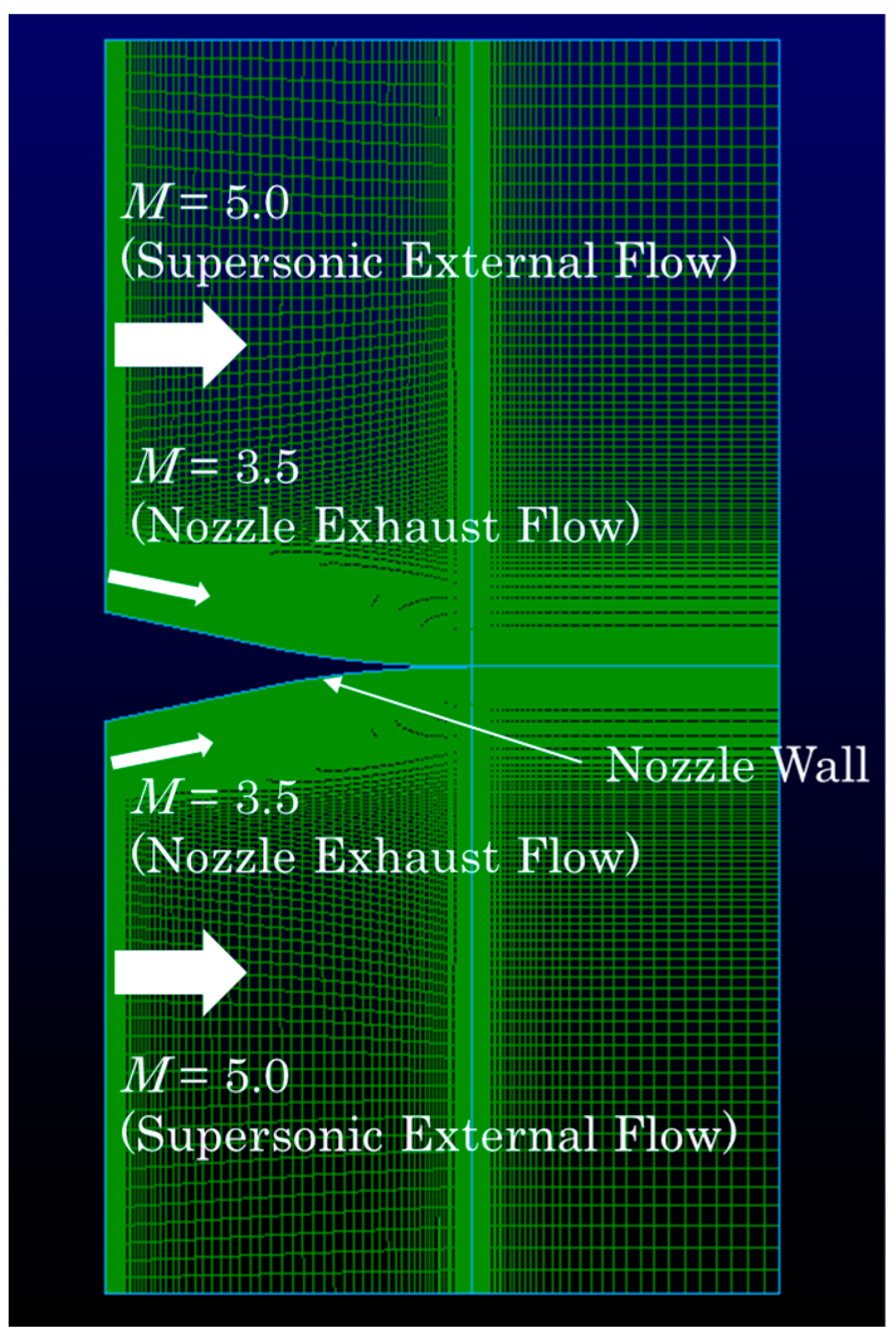
An adopted mesh grid was utilized so that the computation could resolve multiple complex flow characteristics such as jet shear layer, shock waves and jet interactions, and so on. The overall grid used for the CFD simulation to compute the aftbody flowfield that corresponds to the experimental flowfield is presented in Figure 8a. The total number of grids was 13,040. A similar adopted meshing method was employed for the external nozzle Cases 1 to 4. Figure 8b to 8d present the mesh grids used for Cases 1, 3 and 4, respectively. The mesh grid for Case 2 is basically the same as Case 1 except the lower-side cowl is absent. The total number of grids for Cases 2, 3 and 4 are 15,240, 15,240 and 14,859, respectively. The minimum grid resolution was 0.1 mm. All other calculated conditions are summarized in Table 1.
Figure 9 compares flowfield characteristics with regard to the flow structure around the spike nozzle under Mach 2.0 flight conditions. The density distribution is presented. The color bar represents the normalized density based on the density value obtained in the freestream region. Qualitatively, the flowfields obtained by experiment (Figure 9a) and by CFD (Figure 9b) agree with each other in that some remarkable flow structure such as the double oblique shock wave, jet boundary, slip surface, and expansion waves appear.
In order to ensure the quantitative accuracy of the computation, Figure 10 compares the spike wall surface pressure distribution for the aforementioned flow conditions obtained from the experiment, physics-based analytical model [30], and CFD. The pressure distributions obtained from the experiment and the prediction by the analytical model agree well as reported by Takahashi et al. [30]. Some discrepancies between the experiment and the analytical model are attributable to the fact that the analytical model was based on quasi-one-dimensional theory, but the experiment involved two-dimensional flow features and some three-dimensionality as well. The CFD results show better agreement with the experimental data than the analytical model. The discrepancy between the experimental and CFD results is within the errorbar obtained from the experiment. Thus, the spike wall surface pressure distribution is well reproduced qualitatively and quantitatively by the CFD simulation tool developed in this study. Therefore, the computational tool was verified in its accuracy to reproduce the flowfield. This computational tool was used to simulate the external nozzle flowfields of Cases 1 to 4.
4. Results and Discussion
The insights gained from the performance evaluation for the airframe-integrated linear-spike propulsion system adopted for the aftbody portion of the hypersonic aircraft are discussed in this section and cover the following topics of interest: flowfield characteristics, thrust performance by the external nozzle section, and the trim balance.
4.1. Flowfield Characteristics
Flowfields around the aftbody portion for Cases 1 to 4 at the cruise flight condition calculated by CFD are shown in Figure 11: (a) Case 1; (b) Case 2; (c) Case 3; and (d) Case 4. The color bar indicates the pressure distribution on the external nozzle. Case 1 (Figure 11a) shows the flowfield which is similar to the well-known divergent nozzle flowfield because the configuration is a simple straight divergent nozzle. The nozzle flow shows a near optimal-expansion feature because the exit pressure at the external nozzle is approximately equivalent to the ambient pressure. The nozzle exhaust flow flows parallel to the airframe axis for this baseline configuration.
Some remarkable differences in flow feature compared to that seen in Case 1 are seen in Case 2 (Figure 11b). The cell nozzle flow rapidly expands right after the cell nozzle exit as the nozzle wall is an expansion wall for the exhaust flow with an initial angle of 8.7°. This is attributable to the fact that the other side of the nozzle wall (lower body-side cowl) is open, and therefore the nozzle flow expands to the ambient pressure level and is inclined to the wall as it flows along the nozzle wall. Additionally, the flowfield in the aftbody portion involves some outstanding flow features generated by the presence of the supersonic external flow, such as the oblique shock wave emanating from the first interacting location between the external flow and the jet boundary, expansion fans forming behind the oblique shock wave, and slip surface appearing between those two kinds of flows. The expansion waves emanating from the bottom wall of the cell nozzle exit (at the expansion corner) reflect at the jet boundary and the resultant reflected expansion waves eventually form an envelope shock wave. For this kind of large expansion condition of the cell nozzle, this envelope shock wave plays an important role in translating ambient pressure to the spike nozzle surface [22].
Case 3 (Figure 11c) shows a similar flow structure to that seen in Case 2 (Figure 11b) but with some distinct differences. The flow feature near the nozzle exit is similar to that of Case 2 such as in terms of the core length and the oblique shock wave angle, but its expansion is larger as the initial wall inclination angle is larger than that of Case 2. At the interaction between the cell nozzle exhaust flow and the external flow, the external flow generates an oblique shock wave at the first contact with the jet boundary. This feature is also similar to that of Case 2 but is larger in this case. Approximately 200 mm downstream from the cell nozzle exit, some local compression feature is seen toward the end of the wall. This is attributable to the fact that the contour geometry has a compression wall feature for the local exhaust flow.
Distinct differences in flow feature compared to those observed in Cases 1 to 3 are seen for Case 4 (Figure 11d). The cell nozzle exhaust flow flows along the wall, and therefore the flow expansion is limited compared to that observed in Cases 2 and 3. Additionally, the core region of the cell nozzle remains much longer and is inclined toward the wall. The core length is much longer than that seen in Case 1. The nozzle wall contour for this case acts as a compression wall for the cell nozzle flow. This is because the nozzle contour was designed by use of the method of characteristics which provides less wavy flow feature because reflected expansion and compression waves cancel one another out. Therefore, simple flow expansion is seen and the flowfield is not complicated compared to other cases. The elevated wall pressure is a benefit of having the boattail section, which causes the cell nozzle flow inclined to the airframe axis. Note that this is the primary reason in the thrust enhancement by the positive freestream effect. It should be noted that this inclination of the cell nozzle may lose some thrust performance in addition to the boattail drag depending on the flight condition. In order to evaluate the benefit of employing this external nozzle configuration, the thrust performance will be evaluated in a later section.
4.2. Nozzle Surface Pressure Comparison
Since the nozzle surface pressure has a large contribution to generating thrust [8], the spike surface pressure was examined to evaluate the thrust performance of employing the airframe-integrated external nozzle configuration. Figure 12 compares the pressure distribution on the external nozzle among Cases 1 to 4. Note that this pressure distribution was obtained for an assumed two-dimensional flowfield and on the centerline of the airframe.
In Figure 12, the pressure distribution for the baseline case (Case 1) shows that the pressure near the cell nozzle exit until x = 250 mm where the first Mach wave impinges on the nozzle wall is constant because no influence by the flow is seen in this area inside the first Mach wave. This is the core region of the cell nozzle flow. After the first Mach wave impingement point on the wall, the nozzle surface pressure gradually decreases as it goes downstream because expansion waves emanating from the cell nozzle exit impinge on the wall of the simple divergent duct. This feature can be predicted by the Prandtl–Meyer expansion theory. Case 2 shows shorter core length compared to that of Case 1. By the oblique shock wave generated at the first contact between the external flow and the jet boundary, the cell nozzle flow is pushed toward the wall surface and therefore the flow expansion was limited. Consequently, the core region length was reduced. Downstream from the core region, the pressure continues to decrease. The wall pressure becomes lower than the ambient pressure at approximately 220 mm. Considering that the ambient pressure level is 8 kPa for this calculation, the pressure distribution in the remaining 300 mm portion downstream of the x = 220 mm becomes aerodynamic drag. This would indicate that the thrust performance is not beneficial compared to the configuration of Case 1.
Case 3 shows similar core length to that observed in Case 2. However, a significant difference in pressure distribution is seen. The pressure in the core region is much lower than that in Cases 1 and 2. This is attributed to larger expansion by the larger initial expansion angle of the wall as seen in Figure 11c. Right downstream the core region, the pressure increases until x = 200 mm; then the pressure gradually decreases as flow goes downstream. Since the wall contour was designed as a linear-spike configuration, the wall downstream of the core region acts as a compression wall for the cell nozzle flow as mentioned above. Therefore, the wall pressure initially increases. Then, the pressure should continue to increase [8] or remain at the ambient pressure level by balancing with environmental pressure. However, since the nozzle contour was not optimized in this study, a slight pressure decrease downstream of x = 200 mm is seen. The main cause of this decrease is considered to be incident expansion waves emanating from the cell nozzle lip. Pressure values on the wall surface generally stay above the ambient pressure level.
Case 4 shows a distinct difference in pressure distribution compared to the other cases. The core region where the pressure is leveled (i.e., approximately x = 0 mm–50 mm) is much shorter than the other cases; but the pressure value remains at approximately the ideal exit pressure of the cell nozzle. Downstream of the core region, the pressure gradually decreases as flow goes downstream. This observation is different from that given by experiment. In the experiment, the pressure continues to increase as flow moves downstream; however, this case shows the opposite trend. The primary reason for this inconsistency is attributable to the ambient pressure level and flow conditions. The experimental case had relatively large environmental pressure level compared to the cell nozzle exit pressure; the simulated flight condition was at 5 km above sea level. Since the slip surface between the external flow and cell nozzle flow plays a key role in determining the spike surface pressure by balancing these two pressures, the environmental pressure level is important. The environmental pressure in this case is much lower than the cell nozzle exit pressure. Therefore, by balancing the wall pressure with the environmental pressure across the slip surface, the wall pressure was determined and showed a gradually decreasing trend. The slower decrease compared to the baseline case is due to the freestream effect. It should be noted that the boattail flow was assumed to flow on the wall without separation and the boattail Mach number was 5.0 for this case. More systematically parametric study is needed to deepen the feature of the external nozzle flowfield.
4.3. Thrust Breakdown
Figure 13 shows the contribution of each thrust or drag component normalized by the total net thrust in the case of the Mach 5.0 on-design flight condition of Case 1. The ambient pressure was fixed at 8 kPa corresponding to the supersonic cruise altitude of approximately 17.5 km above sea level. The cell nozzle total pressure was 4.0 MPa. In this evaluation, the thrust components of the primary engine thrust generated by the cell nozzle, the thrust generated by the external nozzle surface pressure, and drags associated with the ambient pressure and the skin friction were considered. The boattail drag was also considered for Case 4. Each thrust component was calculated by each corresponding term per Equations (3)–(6) for the baseline case, per Equations (3), (5) and (7) for Cases 2 and 3, and per Equations (3), (8) and (9) for Case 4. These thrust components are compared among Cases 1 to 4.
For the baseline case (Case 1), the thrust generated by the primary engine (denoted as the cell nozzle) obviously has the largest contribution to the total net thrust. The ambient pressure drag is included in Equation (5). The contribution of the external nozzle to the total thrust is small and the skin friction drag is also less significant. For Case 2, though the primary thrust has the largest contribution to the total thrust, the thrust generated by the external nozzle surface pressure shows a notable contribution. Ambient pressure drag has the largest negative impact on the total thrust. This is attributable to the area of the nozzle surface which is exposed to ambient pressure. Therefore, the smaller the airframe base height, the smaller the ambient pressure drag. The total thrust can be slightly smaller than that of the baseline case. Case 3 shows a similar trend to that observed in Case 2. The total thrust is nearly identical to that of Case 2. This is because of the large initial expansion angle of the external nozzle which results in much reduced surface pressure and because of having the compression wall feature toward the end of the spike section which results in recovering the surface pressure as seen in Figure 12. Notably, Case 4 shows a large contribution by the thrust generated by the external nozzle surface pressure. The ambient pressure drag is smaller than in other cases because of the shorter spike length. The boattail drag is also less significant. This is because the ambient pressure level for this premised flight condition was low. The primary engine thrust is reduced because of the boattail inclination. The total net thrust is also nearly identical to those of other cases. Thus, the external nozzle shows no significant impact on the thrust compared to the baseline case for the current cruise condition. Note that the thrust generated by the spike surface pressure could become comparable to the thrust generated by the primary engine depending on the configuration and operation conditions due to the positive freestream effect [8]. This fact indicates that the thrust could nearly be doubled by employing the aerospike nozzle without considering other associated drags at off-design conditions. However, associated drags due to the employment of the aerospike nozzle cannot be neglected. In this study, only a limited number of cases were evaluated in regards to the initial expansion angle of the external nozzle and the boattail angle. These angles would be optimized to obtain the maximum thrust by the employment of the external nozzle. Thus, the external nozzle gives some benefits in terms of increasing thrust and potentially reducing airframe weight.
4.4. Trim Balance Evaluation for the Baseline and Proposed Cases
The flight characteristics with respect to the longitudinal static stability of the aircraft were evaluated by investigating the pitching moment coefficient and the aerodynamic center location, as the flight control characteristics, such as the trim of the aircraft, are crucial to the effectiveness of the propulsion system integration to the airframe. This aspect is especially important for the presently proposed configuration, as the external nozzle of the waverider vehicle generates lift force in addition to generating the thrust force. Note that the wing and other attitude control devices were not considered in this evaluation. The balance of the pitching moment was evaluated in the steady flight (cruise) condition. The x-coordinate of the aerodynamic center (xa.c.) was varied from the airframe leading edge to the trailing edge of the external nozzle in the horizontal direction. The y-coordinate of the aerodynamic center (ya.c.) was on the airframe axis that passes through the airframe leading edge. The pitching moment was then calculated around the aerodynamic center by considering the force balance. As a general definition, a positive pitching moment corresponded to the force acting on the airframe in the nose-up direction while a negative pitching moment was assumed for the force acting in the nose-down direction. The force for calculating the positive pitching moment was the pressure force acting on the surface of the leading edge. The force for the negative pitching moment was the sum of the pressure forces acting on the external nozzle surface; this is particularly applied to the proposed Cases 2 to 4. Note that the force generated by the external nozzle portion for the baseline case did not generate the negative pitching moment accounting for the force direction. The pressure forces for the forebody were calculated as the average value acting on the entire surface of the leading edge portion. The distance for calculating the moment was taken as the length between the aerodynamic center and the midpoint of the area where the force was applied. The cell nozzle thrust was taken into account for the negative pitching moment only for Case 4 since the cell nozzle thrust force direction for other cases is horizontal.
The calculated pitching moment is featured in Figure 14 for each case with the airframe geometry superimposed. The magnitude of the pitching moment was normalized by some factor for the purpose of displaying it with the airframe geometry. For the baseline case, the aerodynamic center or the force equilibrium point where the force balance becomes zero appears near the leading edge. This is because the pitching moment mainly acting on the aircraft for this case is the force acting on the forebody (i.e., no lift force is generated by the external nozzle). Therefore, stabilizers would play an important role in the flight stability and enabling a steady cruise flight.
For Case 2, the aerodynamic center location was found at approximately 300 mm downstream from the leading edge. This location is slightly closer to the airframe midpoint compared to that of Case 1. The aerodynamic center location for Case 3 is nearly identical to that found in Case 2. The primary reason for this observation is attributable to thrusts generated by the external nozzle portion for those two cases are nearly identical as seen in Figure 13. Those locations are relatively upstream side compared to the true airframe center location. Therefore, stabilizers would play a significant role in making a steady flight. Differently, the aerodynamic center location for Case 4 appears at approximately 20% of airframe length downstream from the true airframe center. This is attributable to (a) the thrust generated by the external nozzle pressure was larger than other thrust components and (b) the cell nozzle thrust direction was angled which resulted in increasing the negative pitching moment. For those evaluated cases, some stabilizers or methods such as the redistribution of the fuel tank [41] would be favorable to be applied depending on the flight sequence to ensure a steady flight. Therefore, those proposed configurations are feasible in terms of the trim balance with a possibility for further improvement in the balance by stabilizing devices. As mentioned before, optimization study in terms of the initial expansion angle of the external nozzle portion should be conducted.
4.5. Advanced Configuration of Airframe-Integrated Aerospike Propulsion System
Based on the insights obtained through the conceptual study for the employment of the linear-spike external nozzle, some other configurations for the airframe-integrated external nozzle can be proposed. One of the methods is to install the spike nozzle portion (Case 4) in both sides of the aircraft. Namely, twin-nozzle configuration can be considered. This configuration would eliminate the thrust orientation while generating thrust forces. Figure 15 presents the mesh grids used to compute the flowfield for this configuration. Two linear-spike external nozzles were installed on both sides of the rectangular-shaped airframe fuselage. The top-view of the airframe is displayed. The computed area covered downstream area of the spike nozzle as well as the spike surface. The total number of grids was 39,536. The minimum grid resolution was 0.1 mm as well as that used for other four cases as described in previous sections. The conditions for this calculation are summarized in Table 1.
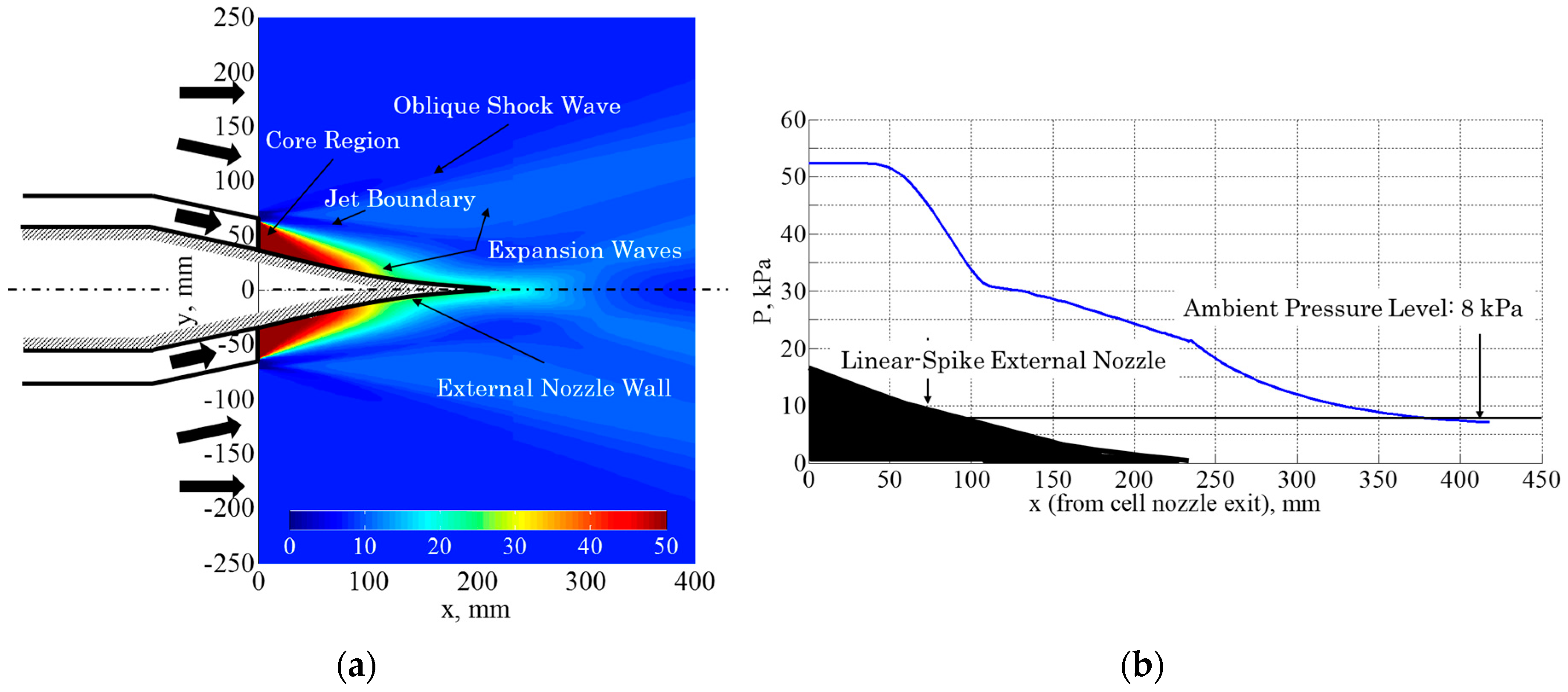
Figure 16a displays the pressure distribution showing the flowfield characteristics for the advanced airframe-integrated aerospike-type external nozzle configuration. The flowfield is similar to that seen in the full-length aerospike nozzle [13,14,15,16,17,19,22,23]. The expansion waves are emanating from the boattail lip. The slip line formed between the external flow and the jet exhaust flow is seen on both sides of the airframe. In the area downstream of the spike nozzle, obviously the jet exhaust flows flowing on both sides of the spike surface interact each other on the center axis of the airframe. There is no wake region behind the spike edge for this condition. Further downstream of the spike edge, the tail shock waves are seen. The pressure distribution and thereby thrust forces generated from both sides of the spike surface are symmetrical. Therefore, no asymmetric force in the lateral direction is generated by this configuration. Note that the thrust vectoring [16,17] is possible by controlling the thrust force generated from each cell nozzle. For example, the right-hand side of the cell nozzle generates the full thrust; and the left-hand side of the cell nozzle generates the 50% of the full thrust, the vehicle will have the momentum which makes the vehicle attitude turning toward the left direction. The pressure distribution on the airframe center axis is presented in Figure 16b. Only the right-hand side is presented by assuming the symmetrical flow structure in terms of the center axis. The wall pressure distribution is basically the same as that observed in Figure 12. The pressure keeps decreasing in the area downstream of the spike edge and then becomes lower than the ambient pressure level at approximately 100 mm downstream the spike edge. Those high-pressure regions contribute to the positive thrust, and therefore this configuration is beneficial for the thrust enhancement and is considered to be feasible as an airframe-integrated external nozzle.
5. Conclusions
The airframe-integrated linear-spike nozzle concept applied for an external nozzle of high-speed aircraft was evaluated with regard to the thrust augmentation capability and the trim balance. The main focus was on the vehicle aftbody. The baseline airframe geometry was first premised to be a hypersonic waverider design. The aftbody portion of the baseline case had an external nozzle comprised of a simple divergent nozzle and was hypothetically replaced with proposed linear-spike external nozzle configurations. The propulsion performance and the benefit in integration of the airframe-propulsion were evaluated by the aid of computational simulation to calculate the pressure distribution on the external nozzle surface. Performance evaluation was mainly conducted by considering the nozzle thrust generated by the aftbody portion and the trim balance at a given cruise condition with zero angle of attack. From the evaluation of the proposed concept for the external nozzle, the following conclusions were drawn.
- (1)
- For the baseline case which was comprised of a simple divergent duct in the external nozzle portion, the external nozzle plays a minor role in aiding thrust. Therefore, the external nozzle part can be cutoff to shorten the overall airframe length. This configuration could be suitable for a steady cruise vehicle.
- (2)
- The linear-spike external nozzles were successfully integrated into the airframe by showing no thrust loss and acceptable pitching-moment distribution for a steady flight. With some stabilizing methods, the aerodynamic center location can be controlled to be a favorable location. Thus, the proposed linear-spike external nozzle concept was shown feasible.
- (3)
- For the current cruise condition and the aftbody configuration, the aerospike-type external nozzle configuration equipped with the boattail was the most beneficial with regard to the thrust generation and the trim balance over the baseline geometry and other linear-spike nozzle configurations. The thrust gain showed was significantly over the boattail drag. With regard to the airframe-integration for hypersonic aircraft, structural design must be considered as well as the thrust performance. While using the aerospike-type equipped with the boattail would be a favorable option, a nozzle configuration that possesses a compression wall feature offers simpler modification of baseline aircraft design with some thrust gain. This configuration would be suitable than the baseline geometry for hypersonic aircraft, the flying trajectory of which involves a wide range of altitudes and distances in dense atmosphere.
In future work, performance evaluation in off-design flight conditions and three-dimensional configuration will be evaluated considering the wing and stabilizers by the aid of CFD. Weight and structural concerns including the internal layout will be considered to evaluate the feasibility of the proposed concept as well as the thrust performance.
Acknowledgments
The authors wish to thank all the staff members at the computational group of the Japan Aerospace Exploration Agency (JAXA) Kakuda Space Center for providing computational environment and insightful discussions. Some intensive computational work was carried out by use of the JAXA Super Computer System Generation 2 (JSS2).
Author Contributions
Hidemi Takahashi proposed and mainly worked on this study from conceptual study, wind tunnel experiment, performance analysis, and management of research collaborations; Toshihiko Munakata intensively carried out the computational work regarding simulation tool development and implementation of the computation under the guidance of Shigeru Sato in technical aspects in computation; Shigeru Sato contributed providing computational tools and computational environment; Hidemi Takahashi wrote this paper entirely.
Conflicts of Interest
The authors declare no conflict of interest.
Nomenclature
| A | area, m2 |
| Cf | skin friction coefficient |
| CL | center line |
| D | drag, N |
| F | force or thrust, N |
| L | length, m |
| M | Mach number |
| mass flow rate, kg/s | |
| P | pressure, kPa |
| R | gas constant, J/(kg·K) |
| T | temperature, K |
| V | velocity, m/s |
| x | coordinate in streamwise direction |
| y | coordinate in vertical direction |
| γ | specific heat ratio |
| θ | angle, rad |
| Subscripts | |
| 0 | stagnation condition |
| a | freestream (for in-flight) or ambient (for still-air) |
| a.c. | aerodynamic center |
| bt | boattail |
| cell | cell nozzle |
| combustor | combustor |
| cruise | cruise condition |
| ini | initial inclination angle of external nozzle wall |
| inlet | inlet |
| LE | leading edge |
| local | local contour |
| nozzle | nozzle |
| j | cell nozzle exit condition |
| sf | skin friction force |
| spike | spike surface |
| straight | straight section |
| throat | throat |
| total | total |
References
- Segal, C. The Scramjet Engine; Cambridge University Press: New York, NY, USA, 2009; pp. 1–15. [Google Scholar]
- McClinton, C.R.; Rausch, V.L.; Shaw, R.J.; Metha, U.; Naftel, C. Hyper-X: Foundation for Future Hypersonic Launch Vehicles. Acta Astronaut. 2005, 57, 614–622. [Google Scholar] [CrossRef]
- Mutzman, R.; Murphy, S. X-51 Development: A Chief Engineer’s Perspective. In Proceedings of the 17th AIAA International Space Planes and Hypersonic Systems and Technologies Conference, San Francisco, CA, USA, 11–14 April 2011. [Google Scholar]
- Cain, T. Scramjet Nozzles. In High-Speed Propulsion: Engine Design—Integration and Thermal Management; RTO Educational Notes RTO-EN-AVT-185; RTO: Neuilly-sur-Seine, France, 2010; pp. 12-1–12-16. [Google Scholar]
- Smart, M.K. Scramjets. In Advances on Propulsion Technology for High-Speed Aircraft; RTO Educational Notes RTO-EN-AVT-150; RTO: Neuilly-sur-Seine, France, 2008; pp. 9-1–9-38. [Google Scholar]
- Curran, E.T. Scramjet Engines: The First Forty Years. J. Propuls. Power 2001, 17, 1138–1147. [Google Scholar] [CrossRef]
- Dalle, D.J.; Torrez, S.M.; Driscoll, J.F. Rapid Analysis of Scramjet and Linear Plug Nozzles. J. Propuls. Power 2012, 28, 545–555. [Google Scholar] [CrossRef]
- Takahashi, H. Performance Evaluation of Airframe-Integrated Aerospike Propulsion Systems in Off-Design Flight Conditions. J. Propuls. Power 2016, 32, 408–419. [Google Scholar] [CrossRef]
- Watanabe, S. Scramjet Nozzle Experiment with Hypersonic External Flow. J. Propuls. Power 1993, 9, 521–528. [Google Scholar] [CrossRef]
- Mitani, T.; Ueda, S.; Tani, K.; Sato, S.; Miyajima, H.; Matsumoto, M.; Yasu, S. Validation Studies of Scramjet Nozzle Performance. J. Propuls. Power 1993, 9, 725–730. [Google Scholar] [CrossRef]
- Takahashi, H. Conceptual Study of Supersonic Transports Employing Airframe-Integrated Advanced Nozzle Configuration. J. Fluid Sci. Technol. 2017, 12, 1–20. [Google Scholar] [CrossRef]
- Korte, J.J.; Salas, A.O.; Dunn, H.J.; Alexandrov, N.M.; Follett, W.W.; Orient, G.E.; Hadid, A.H. Multidisciplinary Approach to Linear Aerospike Nozzle Design. J. Propuls. Power 2001, 17, 93–98. [Google Scholar] [CrossRef]
- Hagemann, G.; Immich, H.; Nguyen, T.V.; Dumnov, G.E. Advanced Rocket Nozzles. J. Propuls. Power 1998, 14, 620–634. [Google Scholar] [CrossRef]
- Nasuti, F.; Onofri, M. Analysis of In-Flight Behavior of Truncated Plug Nozzles. J. Propuls. Power 2001, 17, 809–817. [Google Scholar] [CrossRef]
- Frendi, A.; Nesman, T.E.; Wang, T.-S. Computational and Experimental Study of Linear Aerospike Engine Noise. AIAA J. 2001, 39, 1485–1492. [Google Scholar] [CrossRef]
- Hall, C.; Panossian, H. X-33 Attitude Control Using the XRS-2200 Linear Aerospike Engine. In Proceedings of the 35th AIAA/ASME/SAE/ASEE Joint Propulsion Conference and Exhibit, Los Angeles, CA, USA, 20–23 June 1999. AIAA-99-2936. [Google Scholar]
- Shannon, D.E.; Matthew, D.W.; Stephan, A.W.; Zachary, W.P. Side-Force Amplification on an Aerodynamically Thrust-Vectored Aerospike Nozzle. J. Propuls. Power 2012, 28, 811–819. [Google Scholar]
- Papamoschou, D.; Mayoral, S. Experiments on Shielding of Jet Noise by Airframe Surfaces. In Proceedings of the 15th AIAA/CEAS Aeroacoustics Conference, Miami, FL, USA, 11–13 May 2009; pp. 2009–3326. [Google Scholar]
- Das, I.S.; Khavaran, A.; Krejsa, E.A. A Computational Study of Contoured Plug-Nozzle Jet Noise. J. Sound Vib. 1997, 206, 169–194. [Google Scholar] [CrossRef]
- Sakamoto, H.; Takahashi, M.; Sasaki, M.; Tomita, T.; Kusaka, K.; Tamura, H. An Experimental Study on a 14 kN Linear Aerospike-Nozzle Combustor. In Proceedings of the 35th Joint Propulsion Conference and Exhibit, Los Angeles, CA, USA, 20–24 June 1999. AIAA-99-2761. [Google Scholar]
- Tsutsumi, S.; Teramoto, S.; Nagashima, T. Flow Structure and Performance Analysis of Clustered Linear Aerospike Nozzle. In Proceedings of the 41st AIAA/ASME/SAE/ASEE Joint Propulsion Conference and Exhibit, Tucson, AZ, USA, 10–13 July 2005. AIAA 2005-4307. [Google Scholar]
- Ito, T.; Fujii, K.; Hayashi, A.K. Computations of Axisymmetric Plug-Nozzle Flowfields: Flow Structures and Thrust Performance. J. Propuls. Power 2002, 18, 254–260. [Google Scholar] [CrossRef]
- Miyazawa, T.; Matsuo, A.; Takahashi, H.; Tomita, T.; Tomioka, S. Three Dimensional Numerical Investigation of the Clustered Linear Aerospike Nozzle’s Flow Affected by Changing the Distance between Neighboring Cell Nozzles. In Proceedings of the 49th AIAA/ASME/SAE/ASEE Joint Propulsion Conference, San Jose, CA, USA, 14–17 July 2013. AIAA 2013-3949. [Google Scholar]
- Moes, T.R.; Cobleigh, B.R.; Cox, T.H.; Conners, T.R.; Iliff, K.W.; Powers, B.G. Flight Stability and Control and Performance Results from the Linear Aerospike SR-71 Experiment (LASRE). In Proceedings of the 23rd Atmospheric Flight Mechanics Conference, Boston, MA, USA, 10–12 August 1998. AIAA 1998-4340. [Google Scholar]
- Whitmore, S.A.; Moes, T.R. Base-Drag-Reduction Experiments on the X-33 Linear Aerospike SR-71 Flight Program. J. Spacecr. Rockets 2000, 37, 297–303. [Google Scholar] [CrossRef]
- Ruf, J.; McConaughey, P.K. The Plume Physics behind Aerospike Nozzle Altitude Compensation and Slipstream Effect. In Proceedings of the 33rd Joint Propulsion Conference, Seattle, WA, USA, 6–9 July 1997. AIAA 1997-3218. [Google Scholar]
- Bannik, W.J.; Houtman, E.M.; Schoones, M.M.J. On the Interaction between a Linear Plug Nozzle Exhaust Flow and Supersonic External Flow. In Proceedings of the Third European Symposium on Aerothermodynamics for Space Vehicles, Noordwijk, The Netherlands, 24–26 November 1998. ESA SP-426. [Google Scholar]
- Verma, S.B. Performance Characteristics of an Annular Conical Aerospike Nozzle with Freestream Effect. J. Propuls. Power 2009, 25, 783–791. [Google Scholar] [CrossRef]
- Takahashi, H.; Tomioka, S.; Sakuranaka, N.; Tomita, T.; Kuwamori, K.; Masuya, G. Influence of External Flow on Plume Physics of Clustered Linear Aerospike Nozzles. J. Propuls. Power 2014, 30, 1199–1212. [Google Scholar] [CrossRef]
- Takahashi, H.; Tomioka, S.; Tomita, T.; Sakuranaka, N. Aerodynamic Characterization of Linear Aerospike Nozzles in Off-Design Flight Conditions. J. Propuls. Power 2015, 31, 204–218. [Google Scholar] [CrossRef]
- Fick, M. Performance Modeling and Systems Aspects of Plug Cluster Nozzles. In Proceedings of the 34th AIAA/ASME/SAE/ASEE Joint Propulsion Conference and Exhibit, Cleveland, OH, USA, 13–15 July 1998. AIAA-98-3525. [Google Scholar]
- Fick, M.; Schmucker, R.H. Performance Aspects of Plug Cluster Nozzles. J. Spacecr. Rockets 1996, 33, 507–512. [Google Scholar] [CrossRef]
- Wang, T.S. Effect of Fence on Linear Aerospike Plume-Induced Base-Heating Physics. J. Thermophys. Heat Transf. 2000, 14, 457–463. [Google Scholar] [CrossRef]
- Takahashi, H.; Tomioka, S.; Sakuranaka, N.; Tomita, T.; Kuwamori, K.; Masuya, G. Effects of Plume Impingements of Clustered Nozzles on the Surface Skin Friction. J. Propuls. Power 2015, 31, 485–495. [Google Scholar] [CrossRef]
- Rowbotham, M. XRS-2200 Linear Aerospike Engine: Use of Pro/Engineer for Determining Mass Properties. In Proceedings of the 35th Joint Propulsion Conference and Exhibit, Los Angeles, CA, USA, 20–24 June 1999. AIAA-99-2334. [Google Scholar]
- Reid, J. The Effects of Base Bleed on Plug Nozzles; Reports and Memoranda No. 3466; Her Majesty’s Stationery Office: London, UK, February 1965. [Google Scholar]
- Colville, J.R.; Starkey, R.P.; Lewis, M.J. Axisymmetric Inlet Design for Combined-Cycle Engines. J. Propuls, Power 2006, 22, 1049–1058. [Google Scholar] [CrossRef]
- Bulman, M.J.; Siebenhaar, A. Combined Cycle Propulsion: Aerojet Innovations for Practical Hypersonic Vehicles. In Proceedings of the 17th AIAA International Space Planes and Hypersonic Systems and Technologies Conference, San Francisco, CA, USA, 11–14 April 2011. AIAA 2011-2397. [Google Scholar]
- Dissel, A.F.; Kothari, A.P.; Lewis, M.J. Comparison of Horizontally and Vertically Launched Airbreathing and Rocket Vehicles. J. Spacecr. Rockets 2006, 43, 161–169. [Google Scholar] [CrossRef]
- The U.S. Standard Atmosphere 1976; NASA TM-X-74335; U.S. Government Printing Office: Washington, DC, USA, 1976.
- Candel, S. Concorde and the Future of Supersonic Transport. J. Propuls. Power 2004, 20, 59–68. [Google Scholar] [CrossRef]
- Merlin, P.W. Design and Development of the Blackbird: Challenges and Lessons Learned. In Proceedings of the 47th AIAA Aerospace Sciences Meeting including The New Horizons Forum and Aerospace Exposition, Orlando, FL, USA, 5–8 January 2009. AIAA 2009-1522. [Google Scholar]
- Stark, R. Flow Separation in Rocket Nozzles, a Simple Criteria. In Proceedings of the 41st AIAA/ASME/SAE/ASEE Joint Propulsion Conference and Exhibit, Tucson, AZ, USA, 10–13 July 2005. AIAA 2005-3940. [Google Scholar]
- Van Driest, E.R. Turbulent Boundary Layer in Compressible Fluid. J. Aeronaut. Sci. 1951, 18, 145–160. [Google Scholar] [CrossRef]
Figure 1.
Illustration of a center cut of the baseline airframe configuration, describing dimensions of airframe and propulsion systems.
Figure 1.
Illustration of a center cut of the baseline airframe configuration, describing dimensions of airframe and propulsion systems.

Figure 2.
Simulated flight conditions and nozzle expansion conditions.

Figure 3.
Separation conditions plotted against the initial inclination angle of the external nozzle.
Figure 3.
Separation conditions plotted against the initial inclination angle of the external nozzle.
Figure 4.
Illustration of a center cut of the airframe configuration equipped with the airframe-integrated linear-spike aftbody nozzle, describing dimensions of airframe and propulsion systems.
Figure 4.
Illustration of a center cut of the airframe configuration equipped with the airframe-integrated linear-spike aftbody nozzle, describing dimensions of airframe and propulsion systems.
Figure 5.
Flow separation limit of external flow on the boattail.
Figure 6.
Illustration of a center cut of the airframe configuration equipped with the airframe-integrated linear-spike aftbody nozzle with the boattail.
Figure 6.
Illustration of a center cut of the airframe configuration equipped with the airframe-integrated linear-spike aftbody nozzle with the boattail.

Figure 7.
Illustrations of pressure distributions acting on the aftbody surface. (a) Cases 2 to 3; (b) Case 4.
Figure 7.
Illustrations of pressure distributions acting on the aftbody surface. (a) Cases 2 to 3; (b) Case 4.

Figure 8.
Mesh grids used for calculation of the aftbody flowfield. The flow direction is from left to right. The region of interest for computation is the area indicated by the grid. (a) For validation with experiment; (b) Case 1; (c) Case 3; (d) Case 4.
Figure 8.
Mesh grids used for calculation of the aftbody flowfield. The flow direction is from left to right. The region of interest for computation is the area indicated by the grid. (a) For validation with experiment; (b) Case 1; (c) Case 3; (d) Case 4.

Figure 9.
Comparison of qualitative flowfield feature between experiment and CFD for nozzle pressure ratio (NPR) = 49.5 and Mach 2.0 flight condition. Flow direction is from left to right. The color bar represents the normalized density based on the density value in the freestream region. (a) Density distribution obtained by the experiment using the background-oriented schlieren, adopted from Reference [30]; (b) Density distribution obtained by the CFD calculated for the aftbody nozzle flowfield corresponding to the experimental model.


Figure 10.
Comparison of the spike wall pressure distribution among experiment, analytical model, and CFD. The NPR was 49.5 and the external flow Mach number was 2.0.
Figure 10.
Comparison of the spike wall pressure distribution among experiment, analytical model, and CFD. The NPR was 49.5 and the external flow Mach number was 2.0.

Figure 11.
Pressure distributions of each external nozzle configuration showing the flowfield characteristics computed by CFD. The flow direction is from left to right. The location of x = 0 indicates the cell nozzle exit. The color bar represents the static pressure in the unit of kPa. The white region indicates the airframe. (a) Case 1; (b) Case 2; (c) Case 3; (d) Case 4.
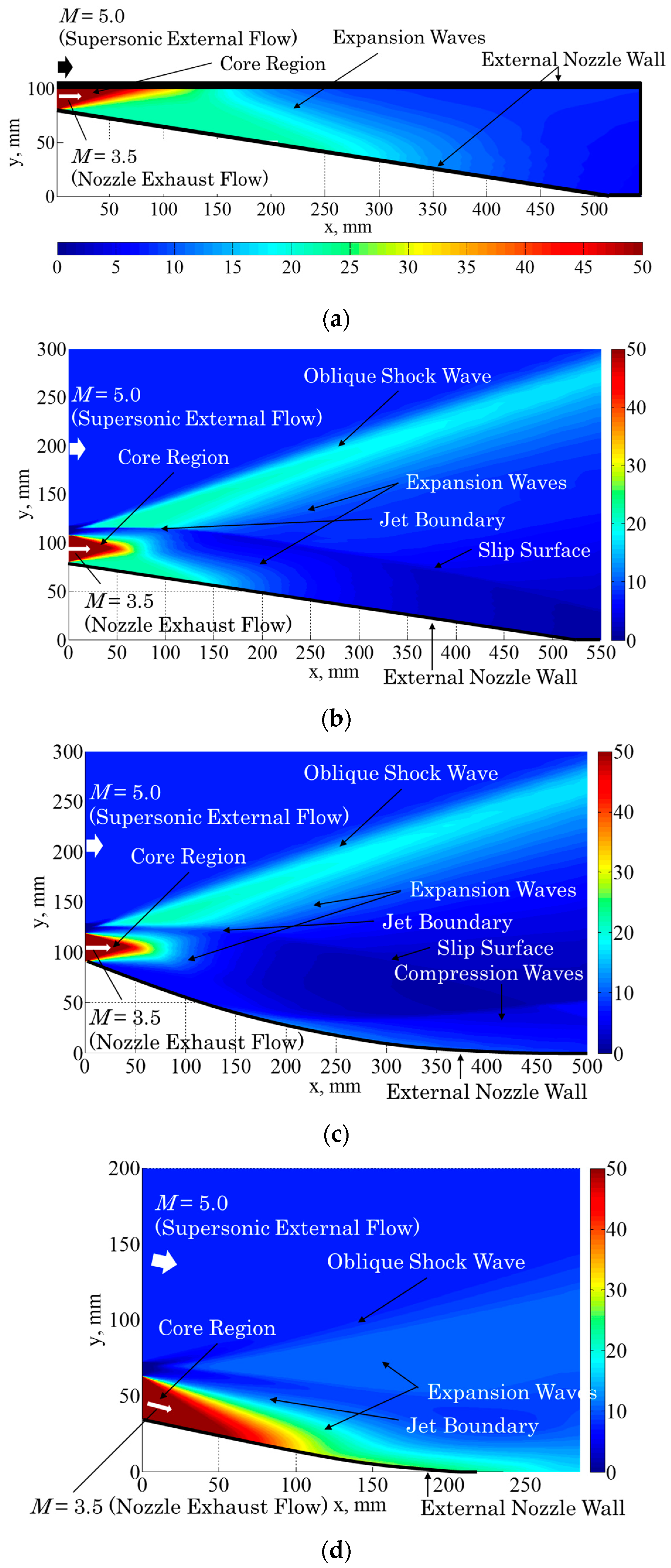
Figure 12.
Comparison of the wall pressure distribution on the external nozzle among Cases 1 to 4. The nozzle surface pressure was obtained by the CFD calculation. The location of x = 0 indicates the cell nozzle exit.
Figure 12.
Comparison of the wall pressure distribution on the external nozzle among Cases 1 to 4. The nozzle surface pressure was obtained by the CFD calculation. The location of x = 0 indicates the cell nozzle exit.

Figure 13.
Thrust breakdown comparing the contribution of each thrust component to the total thrust.
Figure 13.
Thrust breakdown comparing the contribution of each thrust component to the total thrust.
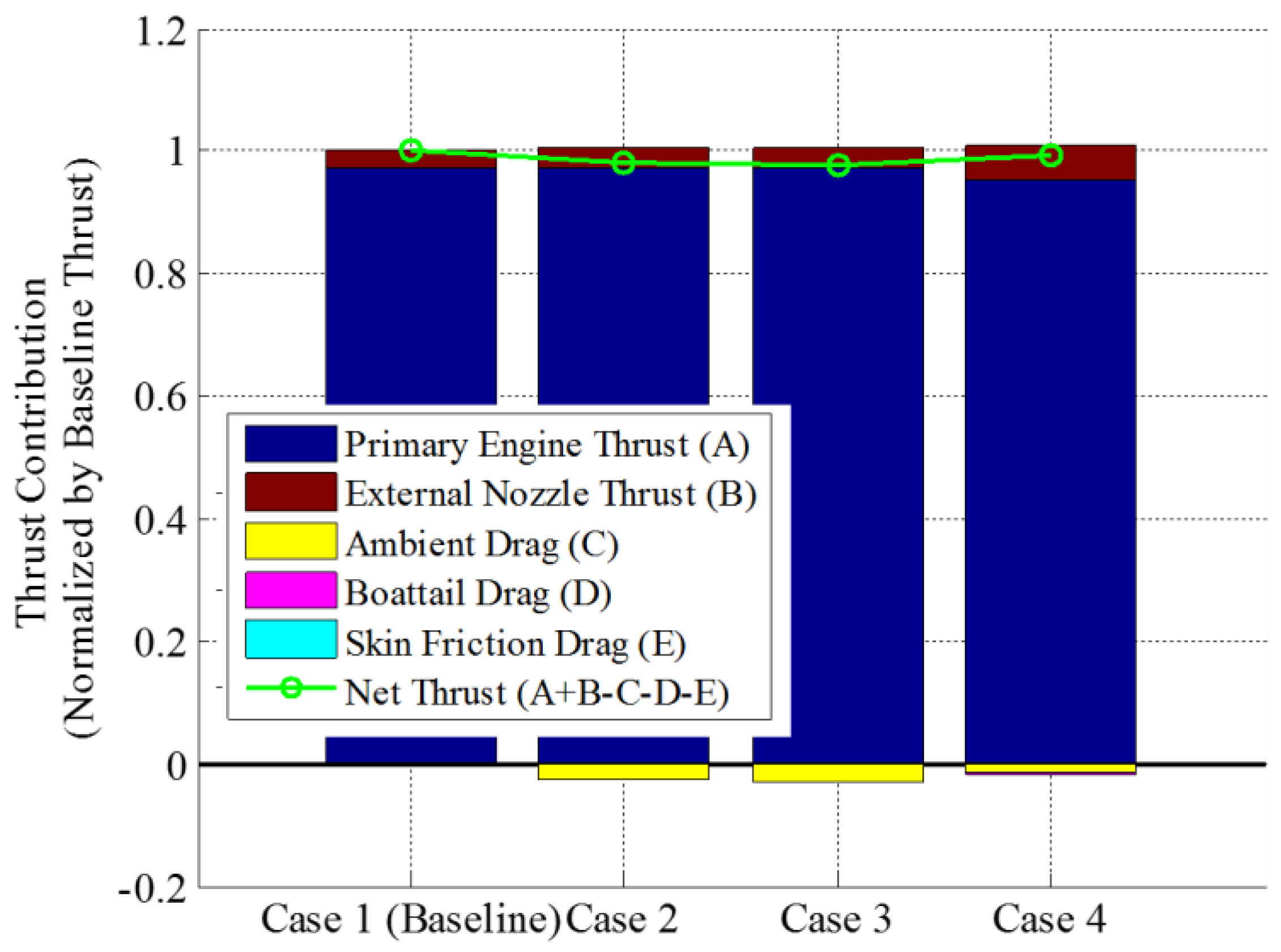
Figure 14.
Pitching moment distributions (red line) superimposed on the center cut of the airframe geometry (black line) for the baseline and proposed cases. The red circle indicates the aerodynamic center location. The flow direction is from left to right. (a) Case 1; (b) Case 2; (c) Case 3; (d) Case 4.
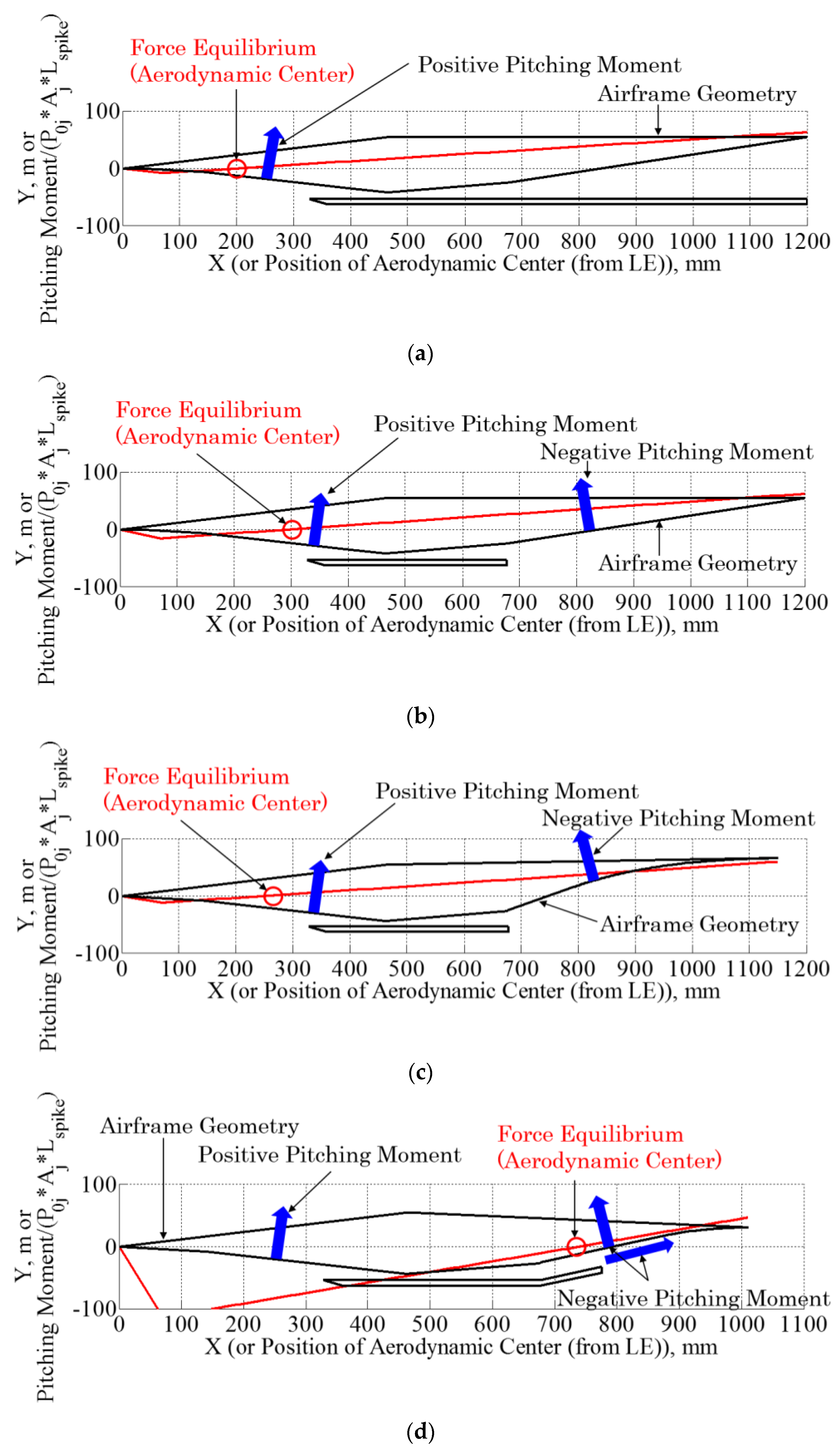
Figure 15.
Mesh grids used for calculation of the flowfield of the advanced configuration. The flow direction is from left to right. The region of interest for computation is the area indicated by the grid.
Figure 15.
Mesh grids used for calculation of the flowfield of the advanced configuration. The flow direction is from left to right. The region of interest for computation is the area indicated by the grid.

Figure 16.
Flowfield characteristics of the advanced external-nozzle case showing the pressure distribution computed by the CFD. (a) Pressure contour map (Top-view) the color bar represents the static pressure in the unit of kPa; (b) Pressure distribution on the center axis.
Figure 16.
Flowfield characteristics of the advanced external-nozzle case showing the pressure distribution computed by the CFD. (a) Pressure contour map (Top-view) the color bar represents the static pressure in the unit of kPa; (b) Pressure distribution on the center axis.


Table 1.
Summary of flow conditions.
| Parameter | Ambient Air | Engine Exhaust Flow |
|---|---|---|
| Specific Heat Ratio | γa = 1.4 | γj = 1.4 |
| Gas Constant, J/(kg·K) | Ra = 287.1 | Rj = 287.1 |
| Total Pressure, kPa | P0a = 8 | P0j = 4000 |
| Total Temperature, K | T0a = 216.6 | T0j = 1500 |
| Mach Number | Ma = 5.0 | Mj = 3.5 |
Table 2.
Summary of external nozzle configurations.
| Case | External Nozzle | Description |
|---|---|---|
| Case 1 | Baseline nozzle | Simple divergent nozzle |
| Case 2 | Straight-ramp external nozzle | Open external nozzle; baseline case without lower side cowl; the nozzle feature is an expansion wall for entire surface. |
| Case 3 | Linear-spike external nozzle | Contoured spike nozzle; the nozzle feature involves a compression wall following to the initial expansion wall. |
| Case 4 | Aerospike-type external nozzle | Angled cell nozzle configuration equipped with the boattail |
© 2018 by the authors. Licensee MDPI, Basel, Switzerland. This article is an open access article distributed under the terms and conditions of the Creative Commons Attribution (CC BY) license (http://creativecommons.org/licenses/by/4.0/).
Share and Cite
MDPI and ACS Style
Takahashi, H.; Munakata, T.; Sato, S. Thrust Augmentation by Airframe-Integrated Linear-Spike Nozzle Concept for High-Speed Aircraft. Aerospace 2018, 5, 19. https://doi.org/10.3390/aerospace5010019
AMA Style
Takahashi H, Munakata T, Sato S. Thrust Augmentation by Airframe-Integrated Linear-Spike Nozzle Concept for High-Speed Aircraft. Aerospace. 2018; 5(1):19. https://doi.org/10.3390/aerospace5010019
Chicago/Turabian StyleTakahashi, Hidemi, Toshihiko Munakata, and Shigeru Sato. 2018. "Thrust Augmentation by Airframe-Integrated Linear-Spike Nozzle Concept for High-Speed Aircraft" Aerospace 5, no. 1: 19. https://doi.org/10.3390/aerospace5010019
Note that from the first issue of 2016, this journal uses article numbers instead of page numbers. See further details here.