
Gaskinetic Modeling on Dilute Gaseous Plume Impingement Flows

Department of Mechanical Engineering-Engineering Mechanics, The Michigan Technological University, Houghton, MI 49931, USA
Aerospace 2016, 3(4), 43; https://doi.org/10.3390/aerospace3040043
Submission received: 9 November 2016
/
Revised: 4 December 2016
/
Accepted: 6 December 2016
/
Published: 9 December 2016
(This article belongs to the Special Issue Fluid-Structure Interactions)
Abstract
:This paper briefly reviews recent work on gaseous plume impingement flows. As the major part of this paper, also included are new comprehensive studies on high-speed, collisionless, gaseous, circular jet impinging on a three-dimensional, inclined, diffuse or specular flat plate. Gaskinetic theories are adopted to study the problems, and several crucial geometry-location and velocity-direction relations are used. The final complete results include impingement surface properties such as pressure, shear stress, and heat flux. From these surface properties, averaged coefficients of pressure, friction, heat flux, moment over the entire flat plate, and the distance from the moment center to the flat plate center are obtained. The final results include accurate integrations involving the geometry and specific speed ratios, inclination angle, and the temperature ratio. Several numerical simulations with the direct simulation Monte Carlo method validate these analytical results, and the results are essentially identical. The gaskinetic method and processes are heuristic and can be used to investigate other external high Knudsen (Kn) number impingement flow problems, including the flow field and surface properties for a high Knudsen number jet from an exit and flat plate of arbitrary shapes. The results are expected to find many engineering applications, especially in aerospace and space engineering.
1. Introduction
Gaseous jet impingement on a plate is a fundamental fluid dynamic problem with many reports and applications in the literature, for example [1,2,3,4,5,6], just to name a few. As the counterpart to the continuum flow situation, highly rarefied jet and jet impingement flows provide the other bounding limits and insights to many problems by solely including molecular movements. In many applications involving high Knudsen (Kn) numbers or high speed velocities, the contributions from particle–particle collisions are insignificant. The Kn number is usually defined as , where λ is the molecule mean free path and L is a characteristic length. Several examples include atomic/molecular beams [7,8], materials processing inside vacuum chambers [9], rocket plume effects on spacecraft solar panels [10], and lunar landing vehicles and missions [11,12,13,14,15,16]. In fact, if the exit speed is high relative to the mean thermal speed, molecules leaving the nozzle exit quickly, barely having time for collisions. As such, high-speed, non-dilute, gaseous, plume flows are quite similar to high Kn number flows.
Compressible flows usually can be divided into four regimes according to the Kn number: continuum, velocity slip and temperature jump, transitional, and free molecular or collisionless (Kn > 10). For jet/plume impingement on a plate, there are many studies concentrating on flows in the continuum and near continuum regimes, for example [17,18]. For the transitional flow regime, past investigations relied on particle simulations, such as the direct simulation Monte Carlo (DSMC) method [19].
This paper does not intend to work on the gaseous jet/plume impingement flows in the first three flow regimes. Instead, this paper concentrates on highly dilute plume impingement flows in the collisionless, or free molecular, flow regime. This paper presents recent and new analysis methods to analyze dilute plume impingement flows, with several sets of analytical solutions for the flow field and surface properties. With these analytical solutions, it is feasible to perform perturbations for less rarefied impingement flows in the future.
For collisionless jet or impingement flows from a nozzle exit, most other researchers relied on numerical and experimental studies on the flow field and surface properties, for example [20,21,22]. By comparison, this paper presents new analytical investigation methods leading to exact expressions.
The paper is organized as follows: Section 2 briefly reviews past results on collisionless gaseous jet expanding into a vacuum, and their solutions serve as the foundations to investigate the impingement flow problem; Section 3 presents approaches to analyze plume impingement flows, and the exact results for surface properties for collisionless jet impingement on an inclined, planar, diffuse or specular reflective plate; Section 4 presents similar methods, and solutions to the corresponding jet impingement on an inclined, rectangular, flat, diffuse or specular reflective plate surface, from a round exit. Because the final expressions are quite complex, several particle simulation results are included for validations. The last section summarizes this paper with several conclusions.
2. Background and Gaskinetic Methods to Investigate Plume and Impingement Flows
Dilute gas jet/plume impingement flows rely on the solutions to the problems of a free plume expanding from a nozzle. Another paper [23] will offer reviews and present recent work on free plumes in a vacuum condition. Here, only a few of examples for plume flows are listed. For high-speed, gaseous, collisionless flows out of an exit, many past studies adopted simplifications. For example, Noller [24] proposed a solid angle treatment to implicitly consider the nozzle exit geometry, and he obtained the plume density field expressed with integrations over solid angles that are subtended by a flow field point and many small surface elements; the cosine law/Simons model [25] treats a rocket plume as from a point source; Narasimha’s early investigations [26] indicated that the plume solution is rather complicated with many cosine functions. Another rocket plume treatment, which is also based on collisionless flows, was suggested by Woronowicz [27]. His treatment splits the exit into many small segments; as such, the density and pressure distributions in the flow field can be computed numerically. Furthermore, he proposed the concept of starting surfaces alleviating the difficulty of this problem. Because the plume and plume impingement flows are so important, many communities have been investigating them for many decades. For example, the bi-annual international rarefied gas-dynamics symposiums usually collect papers on gaseous jet impingement [22,28,29] and molecular beams, and the NASA Johnson center developed the versatile DSMC Analysis Code (DAC) package to simulate plume impingement [30,31] on spacecraft surfaces. Kannenberg and Boyd [32] used the cosine law/Simons model [25] and particle simulation method to compute the density of a plume impinging on a flat plate. Vashchenov et al. [33] and his colleagues performed particle simulations of plume flows from a nozzle. Morris [34] provided a good survey on plume impingement in a space environment.
This paper presents recent work on collisionless plume impingement on an inclined plate with a diffuse or specular surface. A diffuse reflection means that when a particle collides on a surface, it bounces in reverse and uniformly inside the solid angle in a local plane. For a specular reflection case, the reflected particles’ normal velocities are reversed, while the tangent moment maintains unchanged. Recently, detailed solutions for collisionless two-dimensional and circular plume flows were developed and reported followed by progress on the corresponding plume impingement problems [35,36,37,38,39]. These plume solutions only consider collisionless flow situations, such as those cold gas flows firing from an electric propulsion device. The collision effects are completely neglected; and for the impingement problem, only surface properties and diffuse reflections are considered. Following the same vein, Chen [40] calculated the collisionless impingement force on a spacecraft solar panel.
For a dilute equilibrium gas flow with a zero average macroscopic velocity, the velocity distribution function (VDF) is described by a full Maxwellian distribution [19,41], with a number density , and a temperature , or where R is the gas constant for a specific gas. It shall be emphasized that is related with the most probable molecular thermal speed, not a temperature. For a flow with a nonzero average value of along the flow or the X direction but zero values along the Y and Z directions, the integration domain maintains the same shape but shifts left along the u-axis by [37,38]. For an impingement flow, the reflective plate effect can be represented with other velocity distributions.
If there are several known VDFs, , within multiple integration domains, , for a specific flow field point, the local macroscopic average bulk number density, velocities, temperature and pressure can be evaluated using those VDFs [37,38]. For the problem of a free jet expanding into a vacuum, there is only one VDF within an integration domain; however, for the problems of free jets impinging on a plate, there are two separated VDFs with two separated integration domains. One of its corresponding integration domains represent the contributions from the free jet, and the other VDF and its integration domain represent the contribution from the reflective plate.
3. Gaseous Jet Impingement on a 2D Inclined Planar Plate
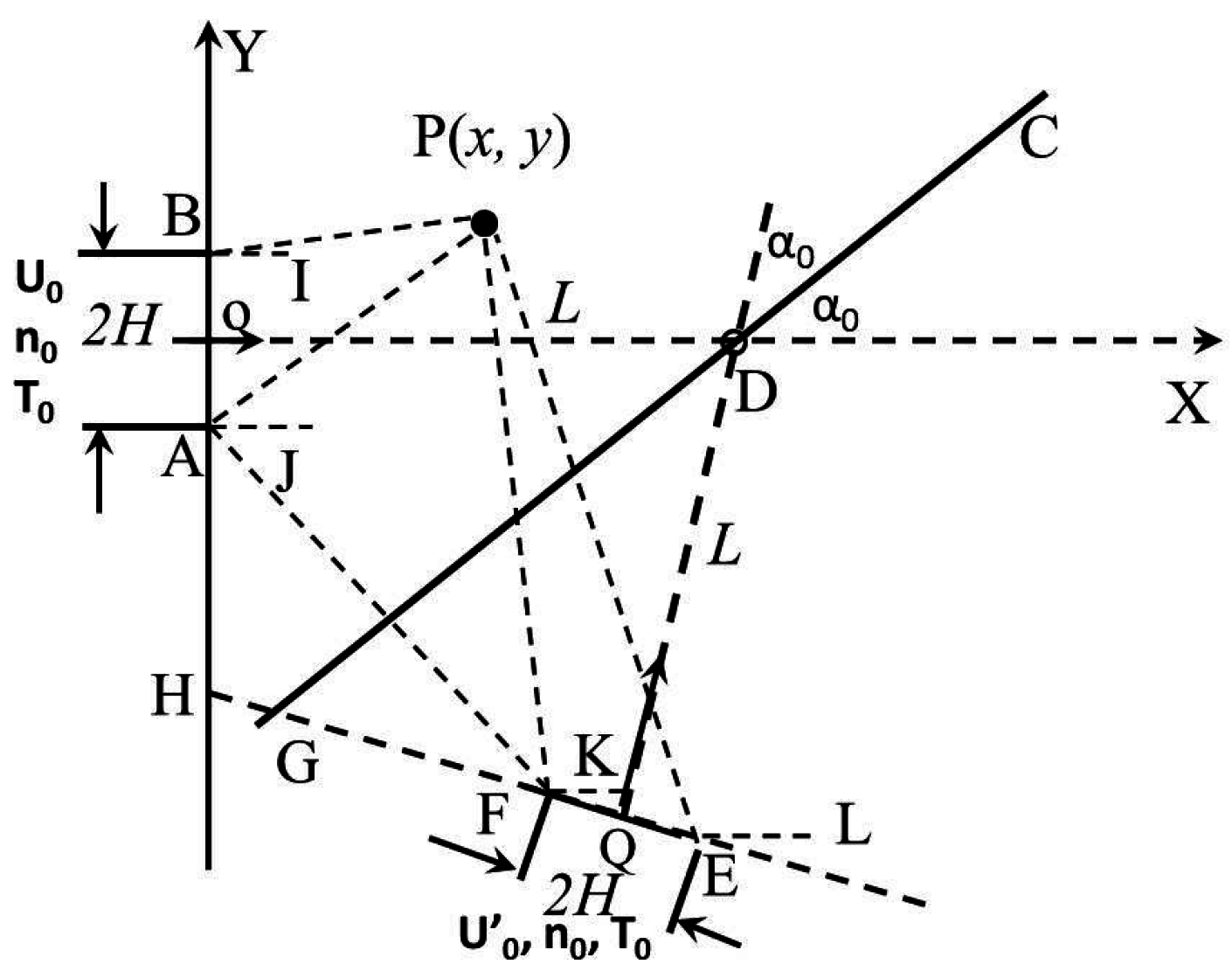
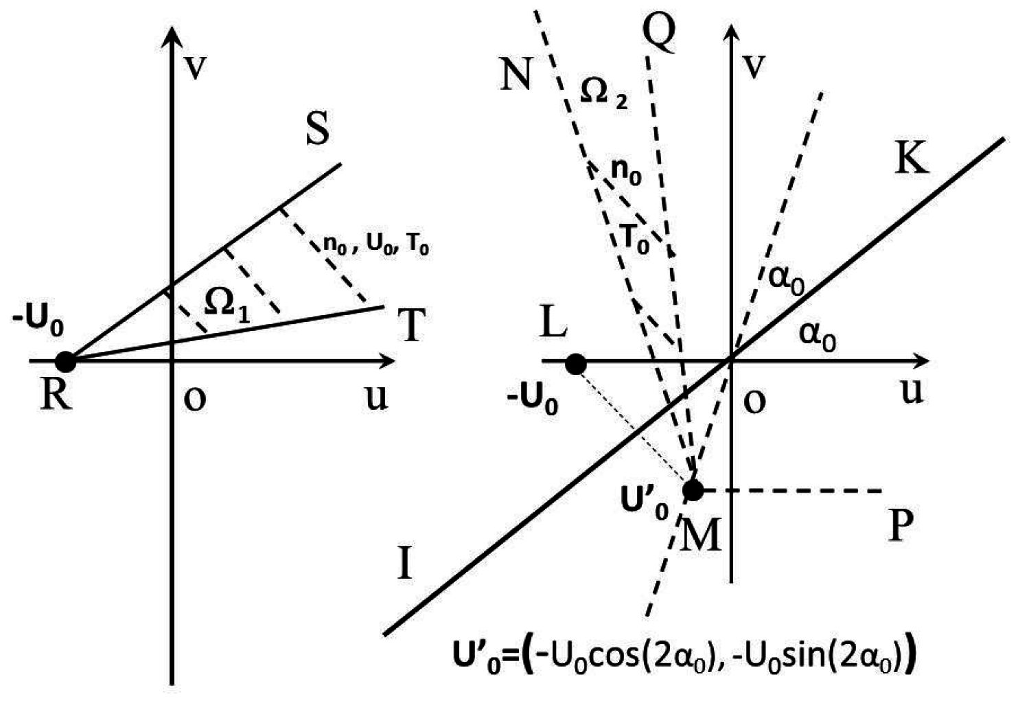
In the past few years, a new gaskinetic approach with a fundamental velocity-location relation was revealed. With that approach, it is possible to obtain exact solutions to several collisionless flow problems [35,36,37,38]. Figure 1 illustrates the problem of collisionless jet impingement on an inclined, diffuse, flat, planar plate; the nozzle exit has a width of , the center-to-center distance from the nozzle exit to the plate is L, the plate semi-width is W, and the plate inclination angle is . The jet bulk properties at the nozzle exit are characterized by a number density , a temperature , and a bulk velocity . The solutions to this problem may find many engineering applications because most surface plates can be represented well by diffuse reflections, and the plate surface may have an inclination angle. Figure 2 shows the corresponding two velocity-phase domains for the problem of free jet impingement on a diffuse reflective plate. The key relation of velocity-direction and geometry-position is, from a specific point, at the exit with a semi-height of H, and only particles with specific velocity components can arrive at a specific point in front of the exit. For the two-dimensional situation, this mapping relation for the free jet problem is:
The solutions to the problem of highly dilute jet impingement on an inclined, flat, diffusive plate are based on the free jet flow problem. At any point in front of the nozzle, the velocity phase consists of two groups of particles, one group of particles are from the nozzle and the other are from the flat, inclined, and diffuse plate. The lines in Figure 2, , , , are parallel to lines , , , and in Figure 1.
The formulas for surface coefficients of pressure, shear stress, and heat fluxes over a diffuse plate, i.e., , , and , are derived with the gaskinetic theory. With very lengthy derivations, the following expressions are obtained:
where and are the integration domains (shown in Figure 2) for the jet and impinged flows, correspondingly; and are the corresponding Maxwellian velocity distribution functions; and are the instantaneous velocity components along the directions normal and parallel to the flat plate surface, for the two groups of particles, correspondingly; s is the distance from the plate center to a point on the plate; ; ; ; is the number density for the Maxwellian distribution function representing the plate surface, and its value is determined by the non-penetration boundary conditions at the plate surface [35,37]. The dynamic pressure at the nozzle exit is used to normalize the surface pressure and friction coefficients, and . Along the plate surface, pressure and heat flux are computed along the direction perpendicular to the plate surface, while shear stress is computed along the direction parallel to the flat plate surface.
To compute the flow field properties at point , contributions from the plate must be included. Different from the specular reflective plate scenario to be discussed in the next section, all diffuse plate points contribute to the flow field properties. A similar mapping relation between geometry-location and velocity-directions is introduced to handle the contributions from the plate surface:
where , and θ is the slope of a line connecting point and a specific point at the plate with a distance of s from the plate center. It can be demonstrated that the follow relation holds:
It was demonstrated that the flow field properties can be integrated out with the above relation [39].
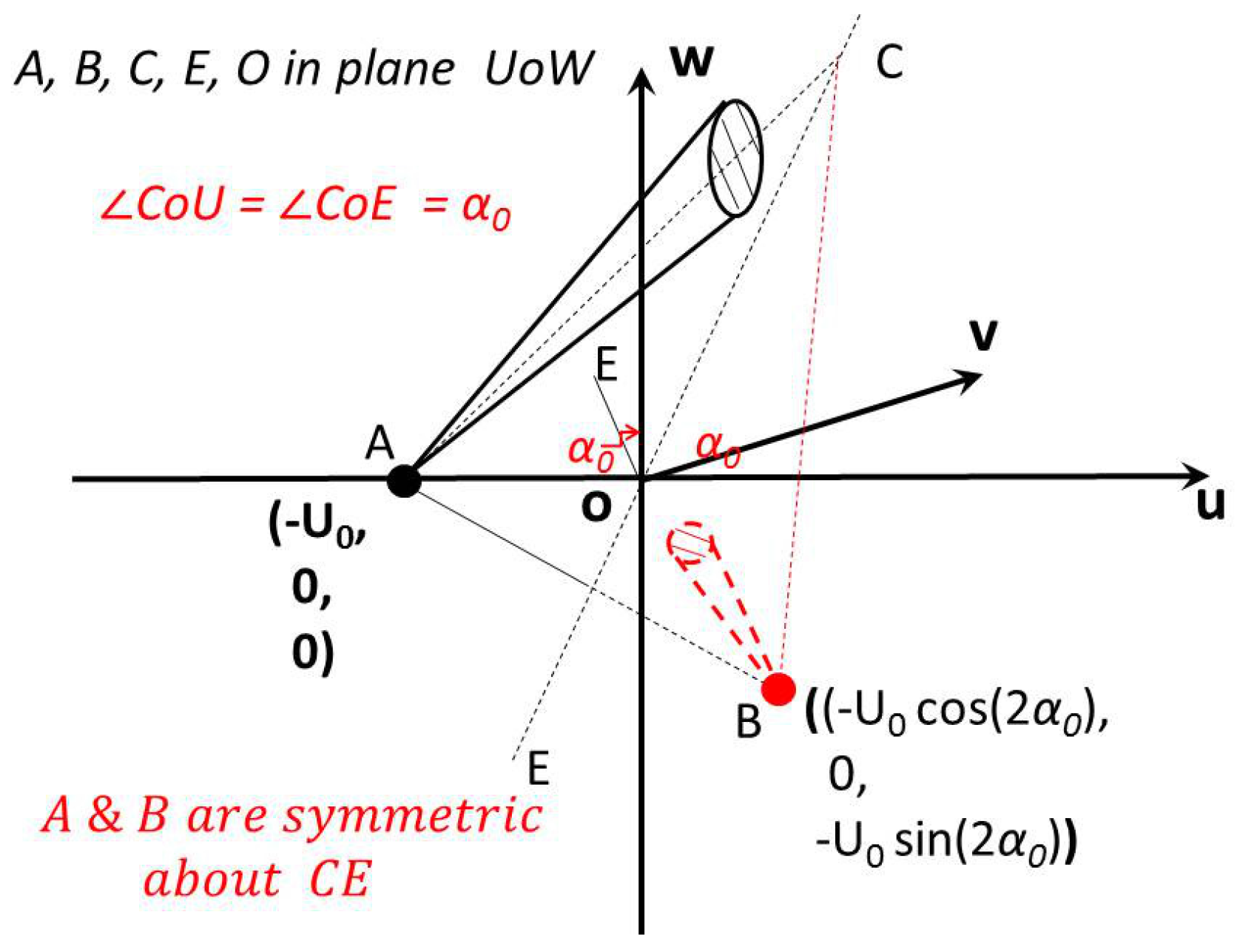
A specular plate is the other limiting case for molecule reflections, corresponding to the diffuse reflection scenario. These two limiting cases bound all practical plate reflections, which are a mixture of specular and diffuse reflections. For specular reflections, the crucial requirement is to satisfy the zero number flux along the normal direction of the wall, while the tangent direction velocity component is unchanged. Figure 3 illustrates the specular reflective plate problem and an approach to solve it. A “virtual” nozzle is mirrored and placed at the other side of the plate, i.e., points F and A, E and B, are symmetric to each other about the specular reflective plate. The virtual jet from the virtual nozzle has the same number density, velocity magnitudes, and temperature as the true nozzle exit, but the directions for the exit velocity components from the true and virtual nozzle must be symmetric about the flat plate. This virtual exit contributes to the flow field properties. Figure 4 shows the velocity phases for a general point between the real nozzle and the plate. As illustrated, there are two integration domains: the solid wedge shape is for the free jet and the other for the virtual nozzle. The latter domain has the same format of a general zero-centered Maxwellian VDF, characterized by the same and . By following this approach, it is convenient to illustrate that the particles’ thermal velocity components are related to the actual and virtual nozzles. Molecules from the true nozzle are confined inside the triangle with a vertex , and those reflected particles, from the virtual nozzle, are confined within another triangular domain with a vertex . The mirrored points F and E can be conveniently computed with vectors and the final coordinates can be represented with two complex numbers:
where the real and imaginary parts are for the x- and y-coordinates, correspondingly. A bounding edge of the integration region for the virtual nozzle has a slope of , i.e., the inclination angle of line in Figure 3. This angle corresponds to in Figure 4. The other integration domain edge is , i.e., the inclination angle of line in Figure 3, and it corresponds to angle in Figure 4. In this paper, the function has a value range of , which is slightly different from the traditional domain for function with a range of . With this treatment, it is shown possible to obtain the exact flow field properties for the planar impingement flow problem [39].
The pressure coefficient on the specular reflective plate surface can be computed conveniently by doubling the free jet local pressure component along the surface normal direction, due to the symmetry relation:
Shear stress and heat flux on the specular plate are zero due to the symmetry condition.
The expressions for flow field properties are quite complex [39] and not included to keep this paper concise. The surface properties are the most important ones for plume impingement flows involving several complex integral terms and need numerical evaluations with a computer. Several DSMC (Direct Simulation Monte Carlo) simulations are performed to validate the flow field and surface properties, and the details of the simulation are available from the literature [39]. A specific DSMC simulation, GRASP (General Rarefied gAs Simulation Package) [42], is adopted for the simulations.
Figure 5 and Figure 6 are the temperature contours for a planar jet impinging on a diffuse or specular reflective plate surface. The results are normalized by the corresponding values at the nozzle exit. The contours for specular reflections are symmetric about the plate surface. Because the temperature expressions heavily involve the density and velocity results, the almost identical agreement between the numerical and analytical temperature contours indicating the expressions for flow field density, velocity components, and temperatures are accurate, for a diffuse or a specular reflective surface.
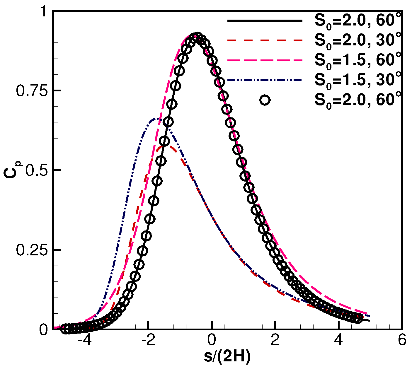
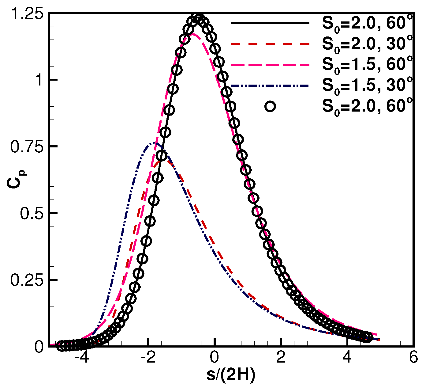
Figure 7 and Figure 8 are the plate surface pressure coefficient distributions. With different parameter combinations of the exit speed ratio, , and the plate inclination angle, , the plate surface pressure profiles show different skewness. Each figure only includes a set of DSMC simulation results for clearer illustrations. As demonstrated, the simulation and analytical results are essentially identical. Also illustrated are the facts that the pressure distributions may not be solely determined by the exit speed ratio, , a smaller exit speed ratio with a larger plate inclination angle can also result in higher pressure distributions. The pressure profiles can be skewed with a smaller inclination angle .
Figure 9 shows diffuse plate surface friction coefficients. It demonstrates that plates with a smaller inclination angle can create large friction coefficients. For the parameter combinations of and , there is a zero point in the profile, indicating that a flow separation may happen at that spot. Figure 10 shows the diffuse plate surface heat flux. The larger the is, the larger the heat flux is. It is also shown that the surface coefficient profiles have perfect agreement between the analytical and numerical simulation results.
4. 3D Diffuse and Specular Reflective Plate Surface Properties
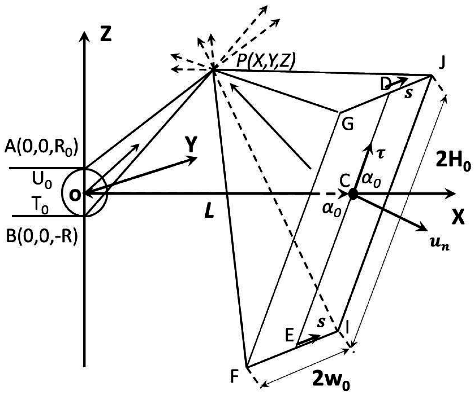
For real engineering applications, the following new work on three-dimensional impingement flows is important, more practical, and more challenging. The scenario of the gas jet from a round nozzle exit on a rectangular flat plate is used to illustrate the new work on collisionless jet impingement flow; however, the method is general and applicable to an exit or a flat plate of arbitrary shapes. The nozzle exit is assumed to have a radius of . The exit center is the coordinate origin. The flat plate inclination angle is , and the center-to-center distance from the nozzle to the flat plate is L. The plate semi-width (horizontal direction) is , the semi-length along the inclined direction is . The gas at the nozzle exit plane is assumed to have a bulk number density of , an average velocity , and a temperature . The plate temperature is assumed to be .
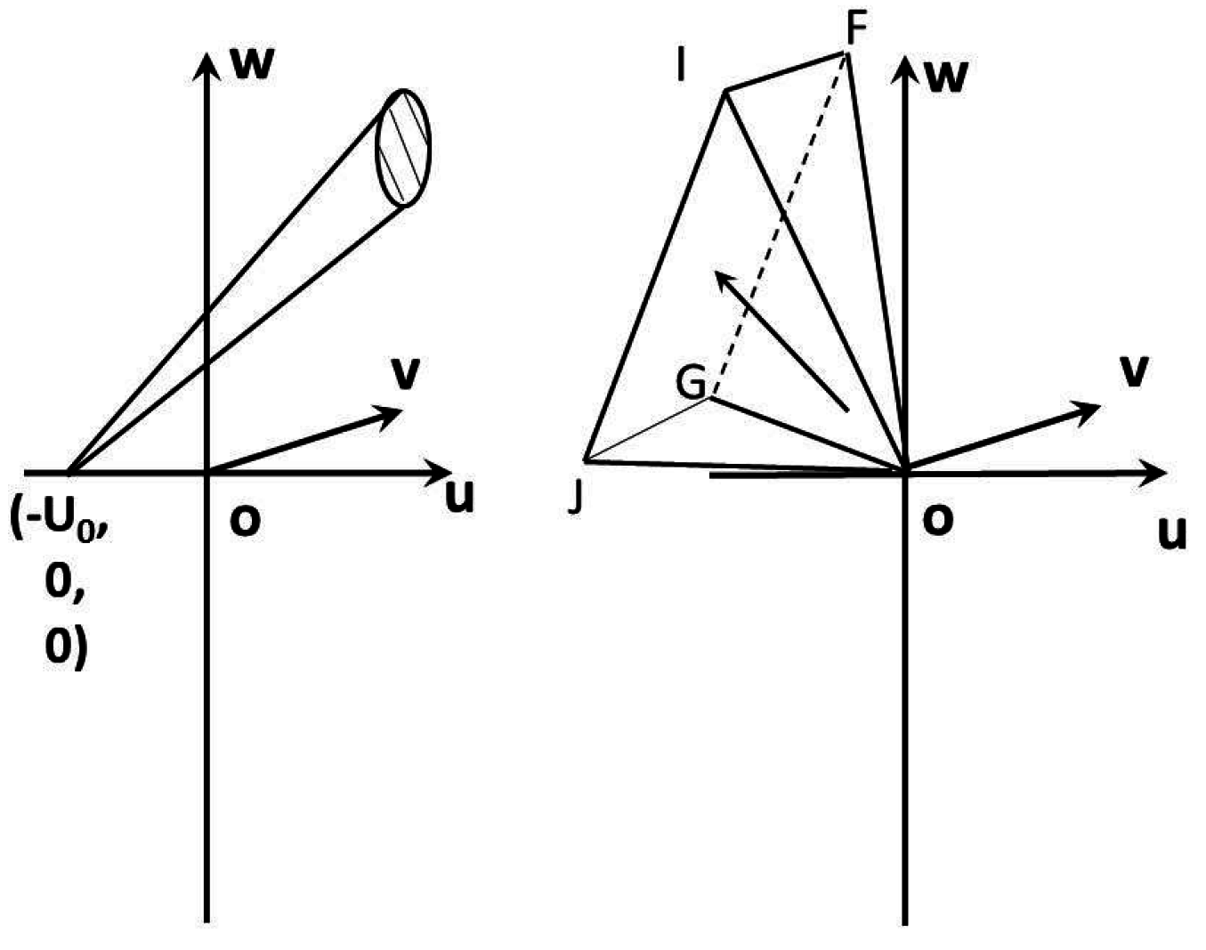
Figure 11 illustrates the situation for a free jet impinging on a diffuse reflective plate. The flow field properties at point have contributions from the free jet and the surface. For the flat plate surface properties, it is assumed that the coordinates for a point on the plate are , which can also be represented by two local coordinates of , along the plate surface: , and . Figure 12 shows the corresponding velocity domain, and the left side is for the free jet, and it has an oblique cone shape starting from and extends to infinity on the right. The right side velocity phase is for the contribution from the diffuse plate surface to the flow field point . It has a pyramid shape with a vertex point and extends to infinity. However, due to the inclination angle, it is possible to have , or , or . This situation is different from the normally set plate situation [37]. There are several parallel relations between Figure 11 and Figure 12; e.g., , , , and .
Figure 13 and Figure 14 show the corresponding specular reflective, flat plate situation. The effect from the plate is equivalently treated by placing a virtual nozzle on the right side of the flat plate. The virtual nozzle is mirrored from the real nozzle, about the plate surface. With this virtual nozzle, particles from the real nozzle can be considered absorbed when they collide at the specular plate surface. Those reflected particles are considered as new particles emitted from the virtual nozzle; hence, the specular plate effects can be considered when computing the flow field properties on the left side, and the plate is neglected. To satisfy the zero number flux or non-penetration condition at the specular plate surface, the virtual nozzle has a position of , and the velocity components are , with the same magnitudes as the jet from the true nozzle. As such, two oblique cones are included in Figure 14. The solid oblique cone in Figure 14 represents the contribution from the true nozzle, while the dashed oblique cone represents the virtual nozzle. Even though both oblique cones are bounded and extending to infinity, only the solid cone has a lower bound for the component (i.e., ). This relationship simplifies the later integrations. Due to the inclination angle and the rotation relations, such a bounding relation cannot be asserted for any velocity components from the virtual nozzle. There are also several parallel relationships between Figure 13 and Figure 14: for example, , .
Based on the gaskinetic theory, the following new solutions to the surface coefficients are obtained. For a diffuse plate, the surface pressure coefficient at point in the global coordinate system, or in the local coordinate system, can be derived as:
where “d” represents a diffuse flat plate, is the instantaneous velocity components (for the two groups of particles, correspondingly), which are normal to the plate surface, is listed in the Appendix, and .
For a diffuse flat surface, there are two surface friction forces and both depend on . The friction coefficient for the force parallel to line in Figure 11 is:
where is the instantaneous velocity components (for two groups of particles correspondingly) that are parallel to the plate surface.
The other friction force is along the or direction, parallel to line in Figure 11, and is the exit radius. The corresponding coefficient is:
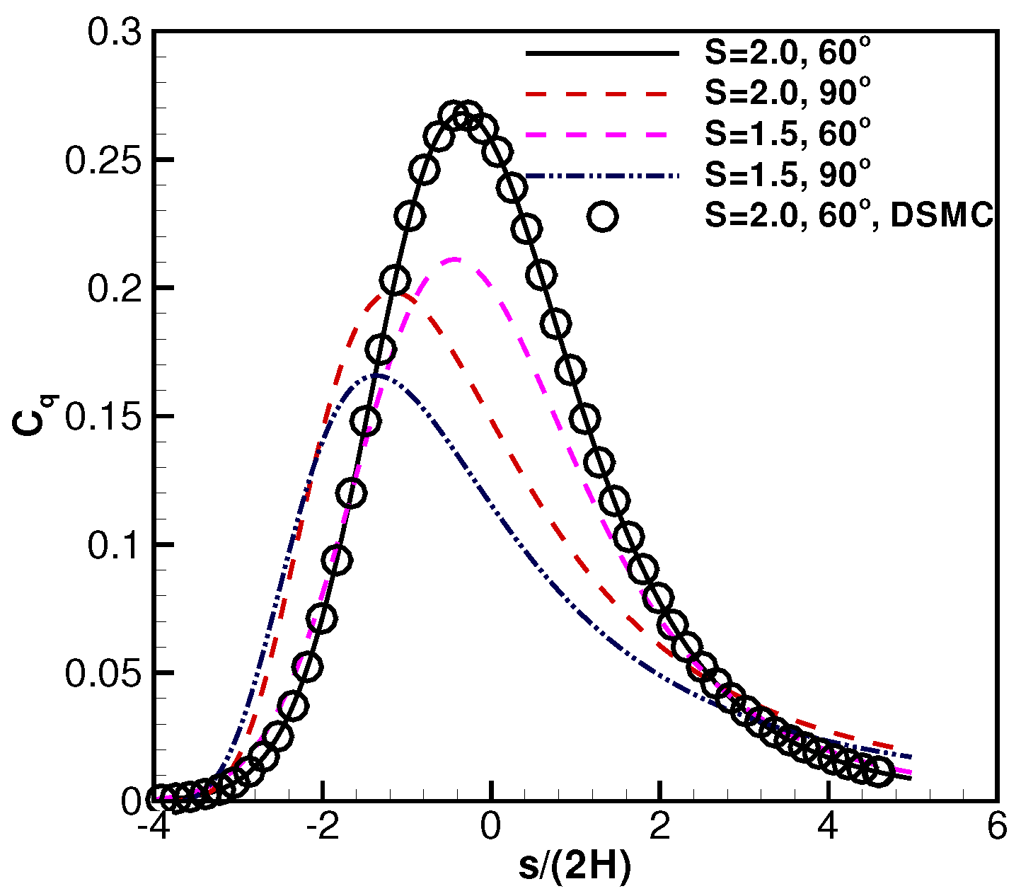
where . By definition, the heat flux is along the plate normal direction, and the coefficient reads:
where , and is listed in the Appendix. The expressions for a diffuse plate surface are complex and the surface temperature can affect these coefficients.
For a specular surface, the shear stress and heat flux are zero due to the symmetry, and the surface pressure coefficient is simply two times the contribution from the free jet to the surface:
The plate temperature does not have any effects on the plate surface pressure coefficient.
Most of the above analytical solutions and expressions involve complex integrations that need numerical evaluations with a computer. Due to their complex expressions, several DSMC numerical simulations for validations are performed. The simulation package is GRASP [42]. In these simulations, the nozzle exit diameter is set as 1.0 m, the center-to-center distance from the exit to the plate, L, is chosen as four times the nozzle diameter. Both the plate semi-length and the semi-height are set as the same length of L. The gas from the exit is Argon, the bulk temperature is K, and the characteristic speed ratio is . The flat plate surface temperature is K, and the plate inclination angle is .
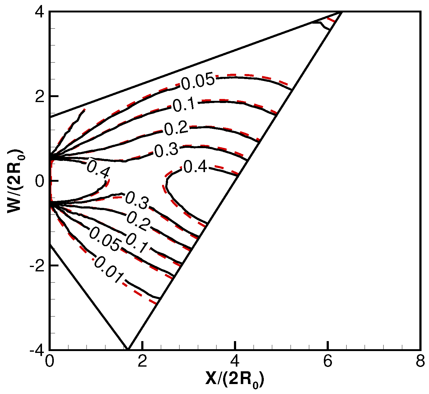
Figure 15 and Figure 16 show the pressure contours in the vertical plane, , passing through the nozzle exit. As shown, there are gas accumulations in the impingement center region. In general, the numerical and analytical solutions are essentially identical. Due to the same reason that the pressure results strongly depend on the number density and velocity components, the good agreement of pressure contours indicates that the flow field density and velocity component results are also correct.
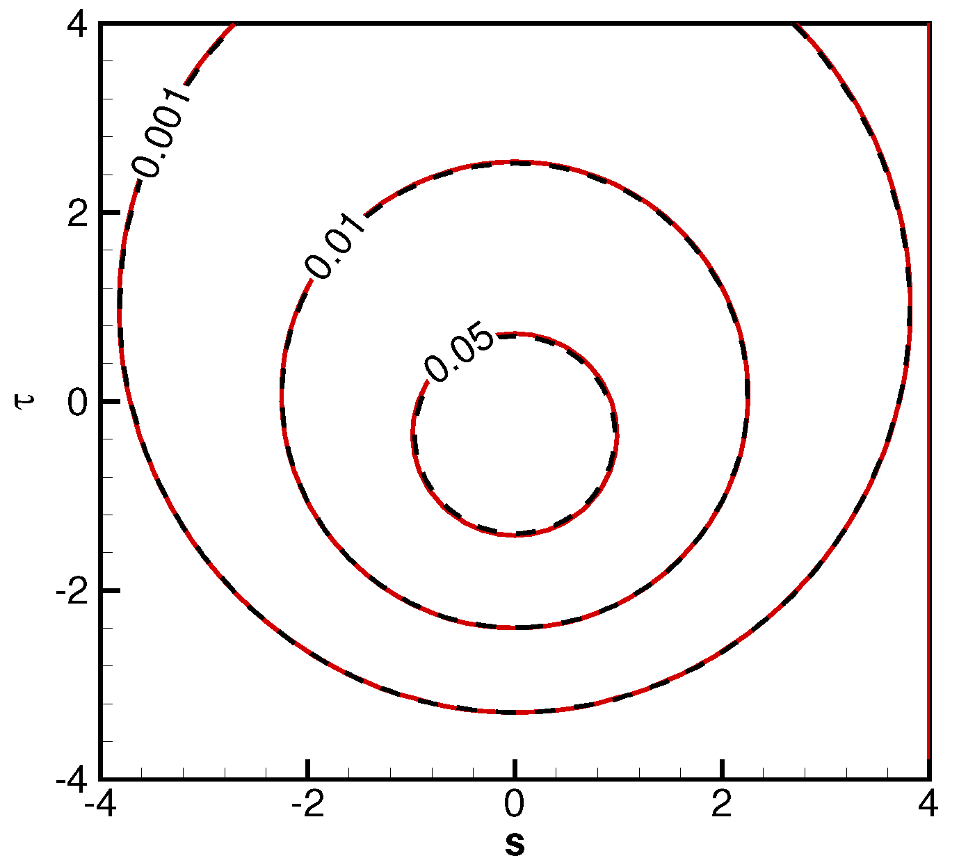
Figure 17 and Figure 18 show the surface pressure coefficients. In these two figures, local coordinates along the horizontal and the inclined directions are adopted. The symmetric patterns from the left to the right are evident, and for these parameter combinations, the specular reflective plate scenario has a slightly higher value at the impingement center. Figure 19 and Figure 20 are the shear stress coefficients along the inclination and horizontal directions for a diffuse reflective plate. The sign on the skin friction coefficient indicates the flow direction. Figure 19 indicates, at the upper plate surface, gas flows upwards with positive friction coefficients, and at the lower plate surface, gas flows downwards with negative friction coefficients. There are stagnation lines with zero shear stress. Figure 21 shows the heat flux distributions at a diffuse reflective plate. At a specific point beneath the plate center, the heat flux reaches the highest value.
5. Averaged Surface Properties for Gaseous Plume Impinging Flows
The considerations of an inclined plate angle are important with many practical and important applications. The validations of flow field and surface properties offer solid foundations to compute the global or average loads on the whole flat plate. These properties include force, moment, torque, heat flux, and the center-to-center distance from the moment to the plate. These averaged properties are named , , , , , and . Let us take the 3D impingement flow results as an example. Because the plate setup is symmetric, the total shear stress along the horizontal direction (y-axis) is zero. However, as shown in this paper, the object surface and the nozzle can have arbitrary geometric shapes. Hence, in general, the shear stress coefficient, , can also be computed with the expressions obtained in this study. These five properties are defined as follows:
where subscript “p” means the integration domain over the whole flat plate surface, and "S" represents the plate area.
6. Conclusions
The paper includes two parts. The first part reviews recent progress on planar jet impingement on an inclined plate [39], which is the general situation for past work [35,37]. The second part reports new work on dilute plume from a round exit and impingement on a flat plate, and it is general to cover the work in two past papers [36,38].
Several relationships between geometry-locations and velocity-directions are used to solve for the flow field and surface solutions. A virtual nozzle is adopted to investigate the specular reflective plate scenarios. Important surface properties, such as coefficients of pressure, shear stress and heat flux are obtained. By including the inclination angle, the expressions are rather complicated but more general and widely applicable. Several DSMC simulations are performed to validate these new analytical and comprehensive solutions over the plate surface. Essentially identical agreements are observed.
It shall be emphasized that these formulas includes trigonometric, exponential, and error functions. The exact formulas include: (1) near field detailed free jet and impingement flow field properties, including velocity components, density, temperature and pressure; (2) detailed surface properties, including surface slip velocity, pressure, friction, and heat fluxes; (3) effects of plate reflection types, i.e., diffuse or specular; (4) different ratios that have appreciable effects for the diffuse reflective surfaces; and (5) the averaged or total properties, such as the moment coefficients and the center-to-center distances.
These solutions are the counterpart solutions to the continuum jet impingement flow scenario, and they offer new insights. With a quick glance, it is convenient to tell the roles that a physical factor plays in the surface properties (e.g, in Equations (9),(11)–(14), and the inclination angle effects are represented by , , and ); by comparison, numerical simulations can offer results with physical factors buried inside numbers. The speed to evaluate these formulas is considerably faster than simulations. For example, for the 3D impingement flows in Section 4, it only took a few seconds to evaluate the flat plate surface properties, but it took days to perform DSMC simulations.
The new method of treating a specular plate with a virtual nozzle is crucial to solving the flow field properties. In general, the approaches in this work can be extended to analyze collisionless free jet impingement flow from exits with arbitrary shapes onto flat plates of arbitrary shapes. It is also possible to adopt other VDFs (not Maxwellian) for the gas at the nozzle exits and diffuse reflective surface.
Acknowledgments
The author thanks Kai Zhang (The Michigan Technological University, Houghton, MI, USA) for help confirm several equations.
Conflicts of Interest
The author declares no conflict of interest.
Appendix A. Several Important Integrals
References
- Banks, R.B.; Chandresekhara, D.V. Experimental investigation of the penetration of a high-velocity gas jet through a liquid surface. J. Fluid Mech. 1963, 15, 13–14. [Google Scholar] [CrossRef]
- Zuckerman, N.; Lior, N. Jet impingement heat transfer: Physics, correlations, and numerical modeling. Adv. Heat Trans. 2006, 39, 565–631. [Google Scholar] [CrossRef]
- Forooghi, P.; Frohnapfel, B.; Magagnato, F. Simulation of a gaseous jet impinging on a convex heated surface-effect of inlet condition. Appl. Therm Eng. 2016, 105, 1076–1084. [Google Scholar] [CrossRef]
- Remie, M.J.; Cremers, M.G.; Schreel, K.M.; de Goey, L.H. Analysis of the heat transfer of an impinging laminar flame jet. Int. J. Heat Mass Transf. 2009, 50, 2816–2827. [Google Scholar] [CrossRef]
- Miller, N.R. Optimization of Jet Impingement Channel for Near Wall Cooling in Gas Turbine Airfoils. Master’s Thesis, University of Pittsburgh, Pittsburgh, PA, USA, 2013. [Google Scholar]
- Pence, D.V.; Boeschoten, P.A.; Liburdy, J.A. Simulation of compressible micro-scale jet impingement heat transfer. J. Heat Transf. 2003, 125, 447–453. [Google Scholar] [CrossRef]
- Campargue, R. Historical account and branching to rarefied gasdynamics of atomic & molecular beams: A continuing and fascinating Odyssey commemorated by Nobel Prizes awarded to 23 Laureates in physics & chemistry. In Proceedings of the 24th International Rarefied Gasdynamics Symposium, Bari, Italy, 10–16 July 2004.
- Sanna, G.; Tomassetti, G. Introduction to Molecular Beams Gas Dynamics; Imperial College Press: London, UK, 2005. [Google Scholar]
- Maev, R.; Leshchynsky, V. Introduction to Low Pressure Gas Dynamic Spray; Wiley-Vch: Weinheim, Germany, 2008. [Google Scholar]
- Hastings, D.; Garrett, H. Spacecraft-Environment Interactions; Cambridge University Press: Cambridge, UK, 1996. [Google Scholar]
- Choate, R.; Batterson, S.; Christensen, E.; Hutton, R.; Jaffe, L.; Jones, R.; Sperling, F. Lunar surface mechanical properties. J. Geophys. Res. 1969, 74, 6149–6174. [Google Scholar] [CrossRef]
- Immer, C.; Metzger, P.; Hintz, P.E.; Nick, A.; Horan, R. Apollo 12 lunar module exhaust plume impingement on lunar surveyor III. Icarus 2011, 211, 1089–1102. [Google Scholar] [CrossRef]
- Sengupta, A.; Kulleck, J.; Sell, S.; Norman, J.V.; Mehta, M.; Pokora, M. Mars lander engine plume impingement environment. In Proceedings of the IEEE Aerospace Conference, Big Sky, MT, USA, 7–14 March 2009; pp. 1–10.
- Metzger, P. Rocket exhaust cratering: A serious challenge for space exploration. In Proceedings of the 1st Workshop on Granular Materials in Lunar and Martian Exploration, Kennedy Space Center, Orlando, FL, USA, 2–3 February 2005.
- Tosh, A.; Liever, P.A.; Arslanbekov, R.R.; Habchi, S.D. Numerical analysis of spacecraft rocket plume impingement under lunar environment. J. Spacecr. Rockets 2011, 48, 93–102. [Google Scholar] [CrossRef]
- Land, N.S.; Clark, L.V. Experimental Investigation of Jet Impingement on Surfaces of Fine Particles in a Vacuum Environment; National Aeronautics and Space Administration Technical Note: Washington, DC, USA, 1965; p. 2663. [Google Scholar]
- Gatsonis, N.A.; Nanson, R.A.; Lebeau, G.J. Navier-Stokes/DSMC simulation of cold-gas nozzle/plume flows and flight data comparisons. In Proceedings of the 33rd Thermophysics Conference, Norfolk, VA, USA, 28 June–1 July 1999.
- Boyd, I.D.; Ketsdever, A. Interactions between spacecraft and thruster plumes. J. Spacecr. Rockets 2001, 38, 433–440. [Google Scholar] [CrossRef]
- Bird, G.A. Molecular Gas Dynamics and the Direct Simulation of Gas Flows, 2nd ed.; Claredon Press: Oxford, UK, 1994. [Google Scholar]
- Koppenwallner, G. The free molecular pressure probe with finite length slot orifice. In Proceedings of the 14th International Symposium on Rarefied Gas Dynamics, Tsukuba, Japan, 16–20 July 1984; pp. 415–422.
- Dettleff, G. Plume flow and plume impingement in space technology. Prog. in Aerosp. Sci. 1991, 18, 1–71. [Google Scholar] [CrossRef]
- Legge, H. Plume impingement forces on inclined flat plates. In Proceedings of the 17th International Symposium Rarefied Gas Dynamics, Aachen, Germany, 8–14 July 1990; pp. 955–962.
- Cai, C. A new gaskinetic model to analyze facility or dilute background flow effects on weak gaseous jet flows. Aerospace 2016. under processing. [Google Scholar]
- Noller, H.G. Approximate calculation of expansion of gas from nozzles into high Vacuum. J. Vac. Sci. Technol. 1966, 3, 202–207. [Google Scholar] [CrossRef]
- Simons, G.A. Effects of nozzle boundary layers on rocket exhaust plumes. AIAA J. 1972, 10, 1534–1535. [Google Scholar] [CrossRef]
- Narasimha, R. Collisionless expansion of gases into vacuum. J. Fluid Mech. 1962, 12, 294–308. [Google Scholar] [CrossRef]
- Woronowicz, M.S.; Rault, N. On jet flow field analysis and simulation techniques. In Proceedings of the 6th AIAA/ASME Joint Thermophysics and Heat Transfer Conference, Colorado Springs, CO, USA, 20–23 June 1994.
- Hyakutake, T.; Nishida, M. Numerical simulations of rarefied plume impingement. In Proceedings of the 22nd International Symposium on Rarefied Gas Dynamics, Sydney, Australia, 9–14 July 2000; pp. 806–811.
- Legge, H.; Boettcher, R.D. Modeling control thruster plume flow and impingement. In Rarefied Gas Dynamics; Springer US: Boston, MA, USA, 1985; pp. 983–992. [Google Scholar]
- LeBeau, G.J.; Lumpkin, F.E. Application highlights of the DSMC Analysis Code (DAC) software for simulating rarefied flows. Comput. Methods Appl. Mach. Eng. 2001, 191, 595–609. [Google Scholar] [CrossRef]
- Lumpkin, F.E.; Stuart, P.C.; LeBeau, G.J. Enhanced analyses of plume impingement during Shuttle-Mir docking using a combined CFD and DSMC methodology. In Proceedings of the 31st AIAA Thermophysics Conference, New Orleans, LA, USA, 18–20 June 1996.
- Kannenberg, K. C.; Boyd, I.D. Three-dimensional Monte Carlo simulation of plume impingement. J. Thermophys. Heat Transf. 1999, 13, 226–235. [Google Scholar] [CrossRef]
- Vashchenov, P.; Kudryavstev, A.; Khotyanovsky, D.; Ivanov, M. DSMC and Navier-Stokes study of back flow for nozzle plumes expanding into vacuum. In Proceedings of the 24th International Rarefied Gas Dynamics Symposium, Monopoli, Italy, 10–16 July 2004.
- Morris, A.B. Simulation of Rocket Plume Impingement and Dust Dispersal on the Lunar Surface. Master’s Thesis, University of Texas, Austin, TX, USA, 2012. [Google Scholar]
- Khasawneh, K.R.; Liu, H.; Cai, C. Highly rarefied two-dimensional jet impingement on a flat plate. Phys. Fluids 2010, 22, 1–6. [Google Scholar] [CrossRef]
- Khasawneh, K.; Liu, H.; Cai, C. Surface properties for rarefied circular jet impingement on a flat plate. Phys. Fluids 2011, 23, 1–6. [Google Scholar] [CrossRef]
- Cai, C.; Zou, C. A gaskinetic study on planar collisionless jet impingement at a plate. Commun. Comput. Phys. 2013, 4, 960–978. [Google Scholar] [CrossRef]
- Cai, C.; Huang, X. High speed rarefied round jet impingement flows. AIAA J. 2012, 50, 2908–2911. [Google Scholar] [CrossRef]
- Cai, C.; He, X. Detailed flow field and surface properties for high Knudsen number planar jet impingement at an inclined flat plate. Phys. Fluids 2016, 28, 056103. [Google Scholar] [CrossRef]
- Chen, X. The impact force acting on a flat plate exposed normally to a rarefied plasma plume issuing from an annular or circular nozzle. J. Phys. D Appl. Phys. 2010, 43, 315205. [Google Scholar] [CrossRef]
- Vincenti, W.G.; Kruger, C.H. Introduction to Physical Gas Dynamics; Kruger Publishing: Malabar, FL, USA, 1986. [Google Scholar]
- Liu, H.; Cai, C. An object-oriented serial and parallel DSMC simulation package. Comput. Fluids 2012, 57, 65–75. [Google Scholar] [CrossRef]
Figure 1.
Free jet impingement on an inclined planar diffuse reflective plate, , , , , and .
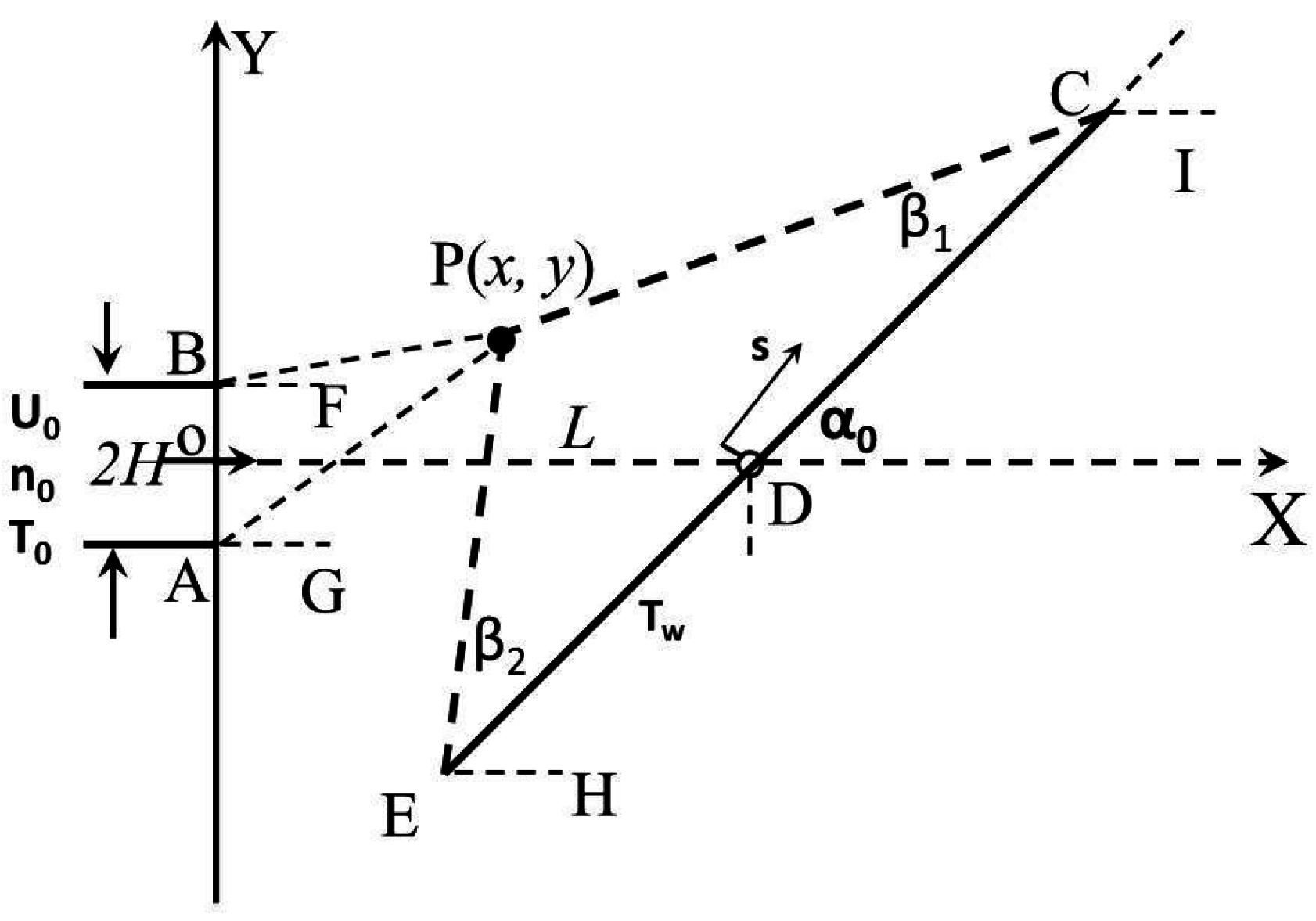
Figure 2.
Velocity spaces for jet impinging on a planar, flat, diffuse reflective plate. Left: , ; Right: , . Integration is for the free jet, and is for the reflected particles.
Figure 2.
Velocity spaces for jet impinging on a planar, flat, diffuse reflective plate. Left: , ; Right: , . Integration is for the free jet, and is for the reflected particles.
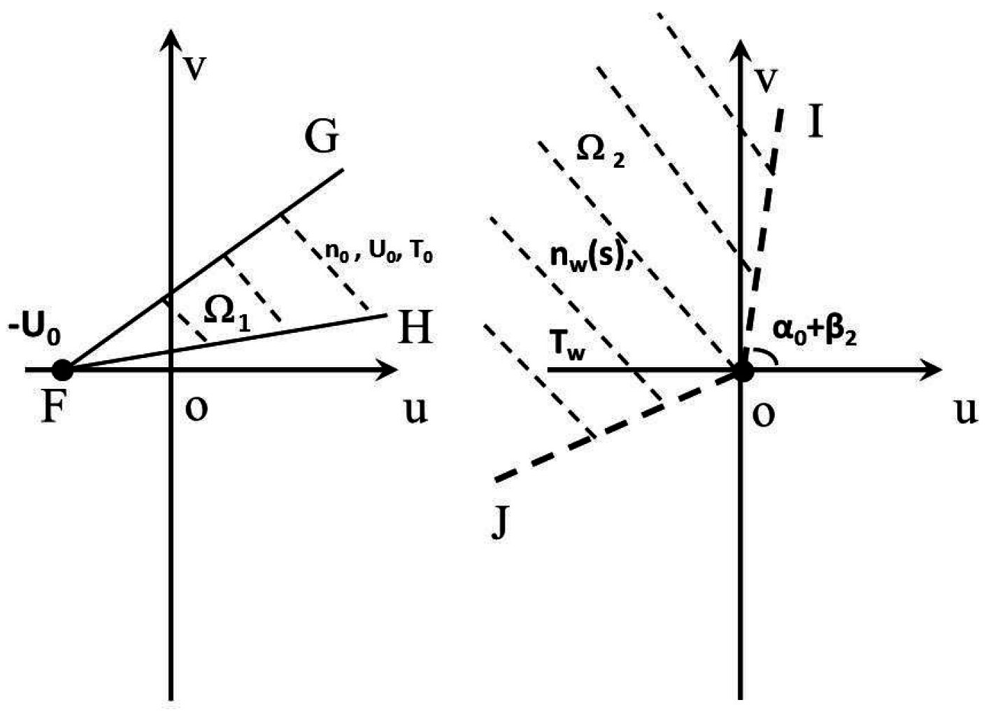
Figure 3.
Free jet impingement on an inclined specular planar reflective plate. , , , , .

Figure 4.
Velocity space for jet impinging on a specular planar reflective plate. , , , . Integration domain, is for the free jet, and is for the reflected particles.
Figure 4.
Velocity space for jet impinging on a specular planar reflective plate. , , , . Integration domain, is for the free jet, and is for the reflected particles.

Figure 5.
Temperature contours for free jet impingement on an inclined, planar, flat, diffuse reflective plate. Solid: analytical; dashed: DSMC (Direct Simulation Monte Carlo).
Figure 5.
Temperature contours for free jet impingement on an inclined, planar, flat, diffuse reflective plate. Solid: analytical; dashed: DSMC (Direct Simulation Monte Carlo).

Figure 6.
Temperature contours for free jet impingement on an inclined, flat, planar, specular reflective plate. Solid: analytical; dashed: DSMC.
Figure 6.
Temperature contours for free jet impingement on an inclined, flat, planar, specular reflective plate. Solid: analytical; dashed: DSMC.
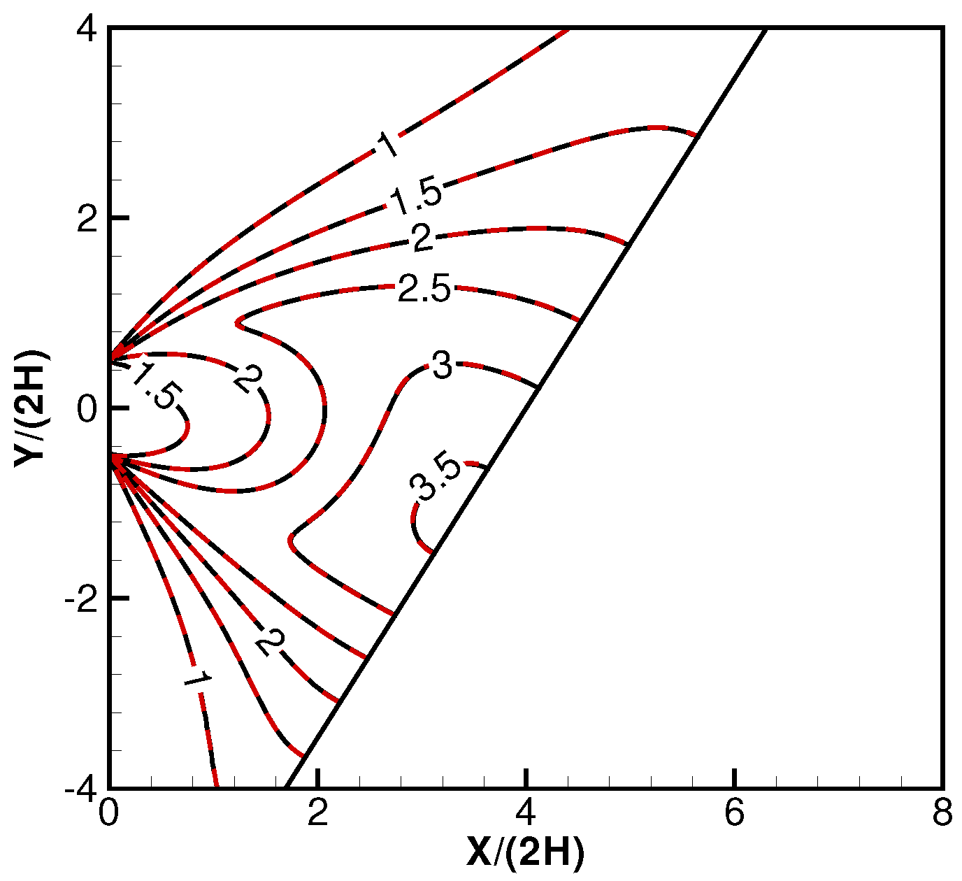
Figure 7.
Diffuse planar plate, surface , . Lines: analytical; symbols: DSMC.

Figure 8.
Specular planar plate, surface . Lines: analytical; symbols: DSMC.

Figure 9.
Diffuse planar plate: surface , . Lines: analytical; symbols: DSMC.

Figure 10.
Diffuse planar plate: surface , . Lines: analytical; symbols: DSMC.

Figure 11.
Illustration of the problem of a round jet impinging on a diffuse reflective plate.

Figure 12.
Velocity phases for the problem of a round jet impinging on a diffuse reflective plate. Left: for the free jet; Right for the reflected particles.
Figure 12.
Velocity phases for the problem of a round jet impinging on a diffuse reflective plate. Left: for the free jet; Right for the reflected particles.

Figure 13.
Illustration of the problem of a round jet impinging on a specular reflective plate. Dashed lines: virtual nozzle.
Figure 13.
Illustration of the problem of a round jet impinging on a specular reflective plate. Dashed lines: virtual nozzle.
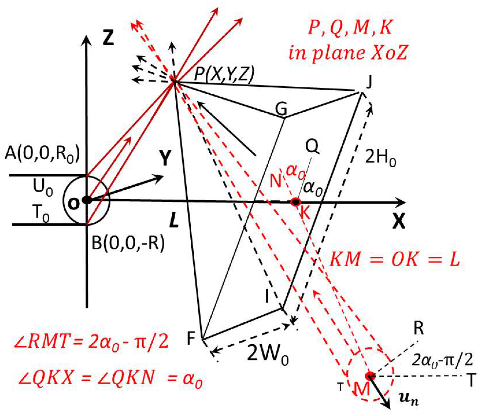
Figure 14.
Velocity phases for the specular reflective plate impingement problem. Solid cone: for the free jet; dashed red cone: reflected particles.
Figure 14.
Velocity phases for the specular reflective plate impingement problem. Solid cone: for the free jet; dashed red cone: reflected particles.

Figure 15.
Pressure contours for free jet impingement on an inclined diffuse rectangular reflective plate, from a round exit, in the middle vertical plane. Results normalized by the static pressure at the nozzle exit. Dashed: analytical; solid: DSMC.
Figure 15.
Pressure contours for free jet impingement on an inclined diffuse rectangular reflective plate, from a round exit, in the middle vertical plane. Results normalized by the static pressure at the nozzle exit. Dashed: analytical; solid: DSMC.
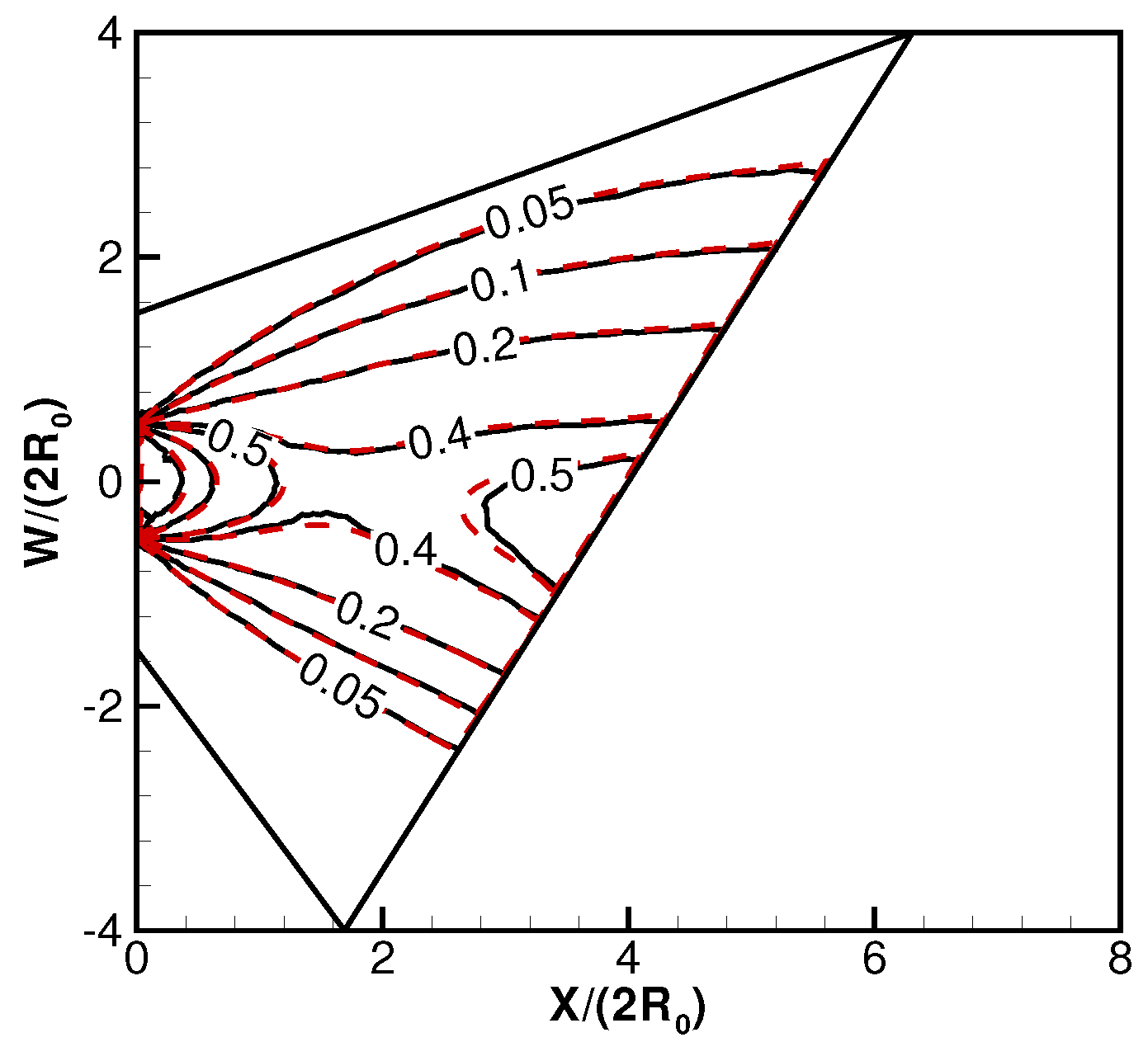
Figure 16.
Pressure contours for free jet impingement on an inclined specular rectangular reflective plate, from a round exit, in the middle vertical plane. Results normalized by the static pressure at the nozzle exit. Dashed: analytical; solid: DSMC.
Figure 16.
Pressure contours for free jet impingement on an inclined specular rectangular reflective plate, from a round exit, in the middle vertical plane. Results normalized by the static pressure at the nozzle exit. Dashed: analytical; solid: DSMC.

Figure 17.
Diffuse plate, pressure contours, , , , . Plate lengths are normalized by the nozzle diameter. Solid: analytical; dashed: DSMC.
Figure 17.
Diffuse plate, pressure contours, , , , . Plate lengths are normalized by the nozzle diameter. Solid: analytical; dashed: DSMC.
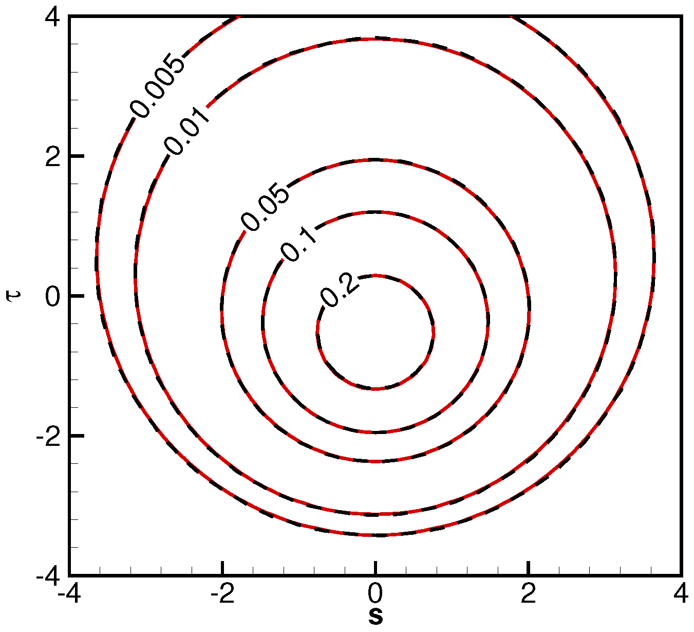
Figure 18.
Specular plate, pressure contours, , , , . Plate lengths are normalized by the nozzle diameter. Solid: analytical; dashed: DSMC.
Figure 18.
Specular plate, pressure contours, , , , . Plate lengths are normalized by the nozzle diameter. Solid: analytical; dashed: DSMC.
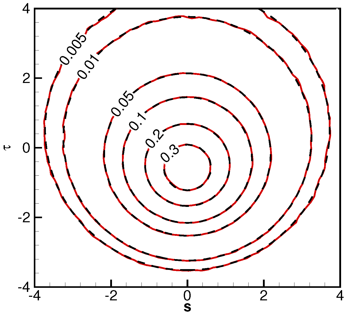
Figure 19.
Diffuse plate, friction coefficient, , , , . Plate lengths are normalized by the nozzle diameter. Solid: analytical; dashed: DSMC.
Figure 19.
Diffuse plate, friction coefficient, , , , . Plate lengths are normalized by the nozzle diameter. Solid: analytical; dashed: DSMC.
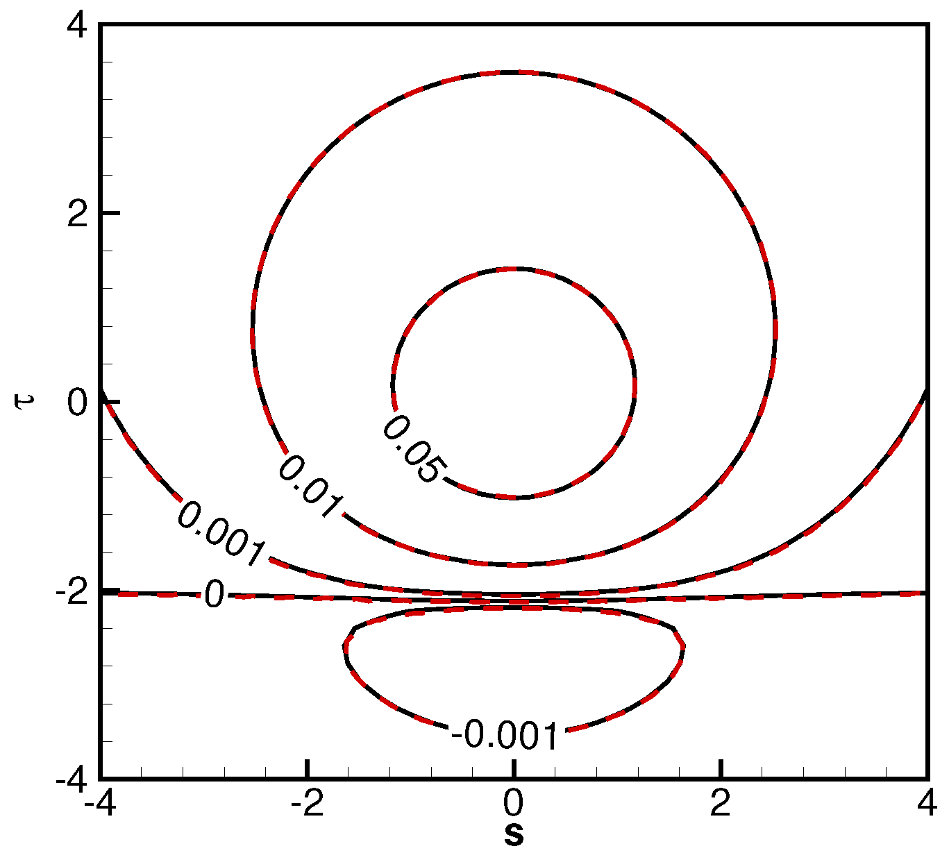
Figure 20.
Diffuse plate, friction coefficient, , , , . Plate lengths are normalized by the nozzle diameter. Solid: analytical; dashed: DSMC.
Figure 20.
Diffuse plate, friction coefficient, , , , . Plate lengths are normalized by the nozzle diameter. Solid: analytical; dashed: DSMC.
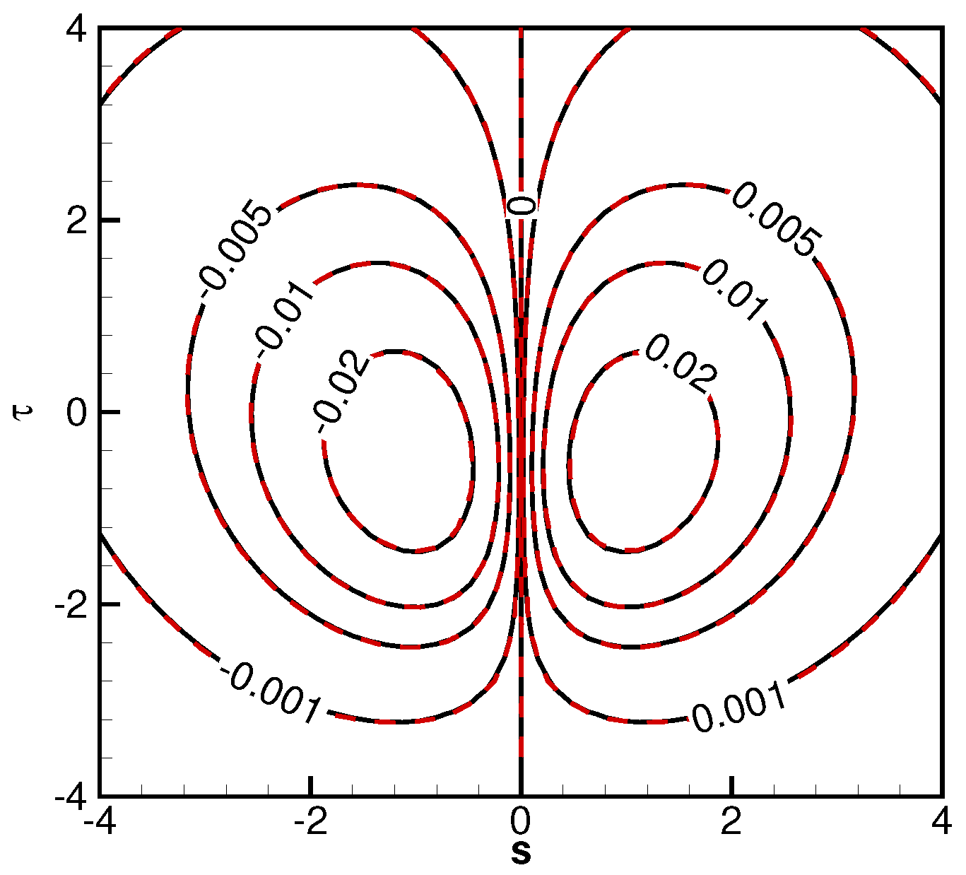
Figure 21.
Diffuse plate, heat flux, , , , . Plate lengths are normalized by the nozzle diameter. Solid: analytical; dashed: DSMC.
Figure 21.
Diffuse plate, heat flux, , , , . Plate lengths are normalized by the nozzle diameter. Solid: analytical; dashed: DSMC.

© 2016 by the author; licensee MDPI, Basel, Switzerland. This article is an open access article distributed under the terms and conditions of the Creative Commons Attribution (CC-BY) license (http://creativecommons.org/licenses/by/4.0/).
Share and Cite
MDPI and ACS Style
Cai, C. Gaskinetic Modeling on Dilute Gaseous Plume Impingement Flows. Aerospace 2016, 3, 43. https://doi.org/10.3390/aerospace3040043
AMA Style
Cai C. Gaskinetic Modeling on Dilute Gaseous Plume Impingement Flows. Aerospace. 2016; 3(4):43. https://doi.org/10.3390/aerospace3040043
Chicago/Turabian StyleCai, Chunpei. 2016. "Gaskinetic Modeling on Dilute Gaseous Plume Impingement Flows" Aerospace 3, no. 4: 43. https://doi.org/10.3390/aerospace3040043
Note that from the first issue of 2016, this journal uses article numbers instead of page numbers. See further details here.