Priority-Based Machine-To-Machine Overlay Network over LTE for a Smart City


Department of Computer Science, Ryerson University, Toronto, ON M5B 2K3, Canada
*
Author to whom correspondence should be addressed.
†
These authors contributed equally to this work.
J. Sens. Actuator Netw. 2018, 7(3), 27; https://doi.org/10.3390/jsan7030027
Submission received: 27 April 2018
/
Revised: 6 July 2018
/
Accepted: 10 July 2018
/
Published: 12 July 2018
(This article belongs to the Special Issue Wireless Sensor and Actuator Networks for Smart Cities)
Abstract
:Long-Term Evolution (LTE) and its improvement, Long-Term Evolution-Advanced (LTE-A), are attractive choices for Machine-to-Machine (M2M) communication due to their ubiquitous coverage and high bandwidth. However, the focus of LTE design was high performance connection-based communications between human-operated devices (also known as human-to-human, or H2H traffic), which was initially established over the Physical Random Access Channel (PRACH). On the other hand, M2M traffic is mostly based on contention-based transmission of short messages and does not need connection establishment. As a result, M2M traffic transmitted over LTE PRACH has to use the inefficient four-way handshake and compete for resources with H2H traffic. When a large number of M2M devices attempts to access the PRACH, an outage condition may occur; furthermore, traffic prioritization is regulated only through age-based power ramping, which drives the network even faster towards the outage condition. In this article, we describe an overlay network that allows a massive number of M2M devices to coexist with H2H traffic and access the network without going through the full LTE handshake. The overlay network is patterned after IEEE 802.15.6 to support multiple priority classes of M2M traffic. We analyse the performance of the joint M2M and H2H system and investigate the trade-offs needed to keep satisfactory performance and reliability for M2M traffic in the presence of H2H traffic of known intensity. Our results confirm the validity of this approach for applications in crowd sensing, monitoring and others utilized in smart city development.
Keywords:
LTE; RACH; PRACH; IEEE 802.15.4; IEEE 802.15.6; non-saturation operating regime; backoff error; smart city1. Introduction
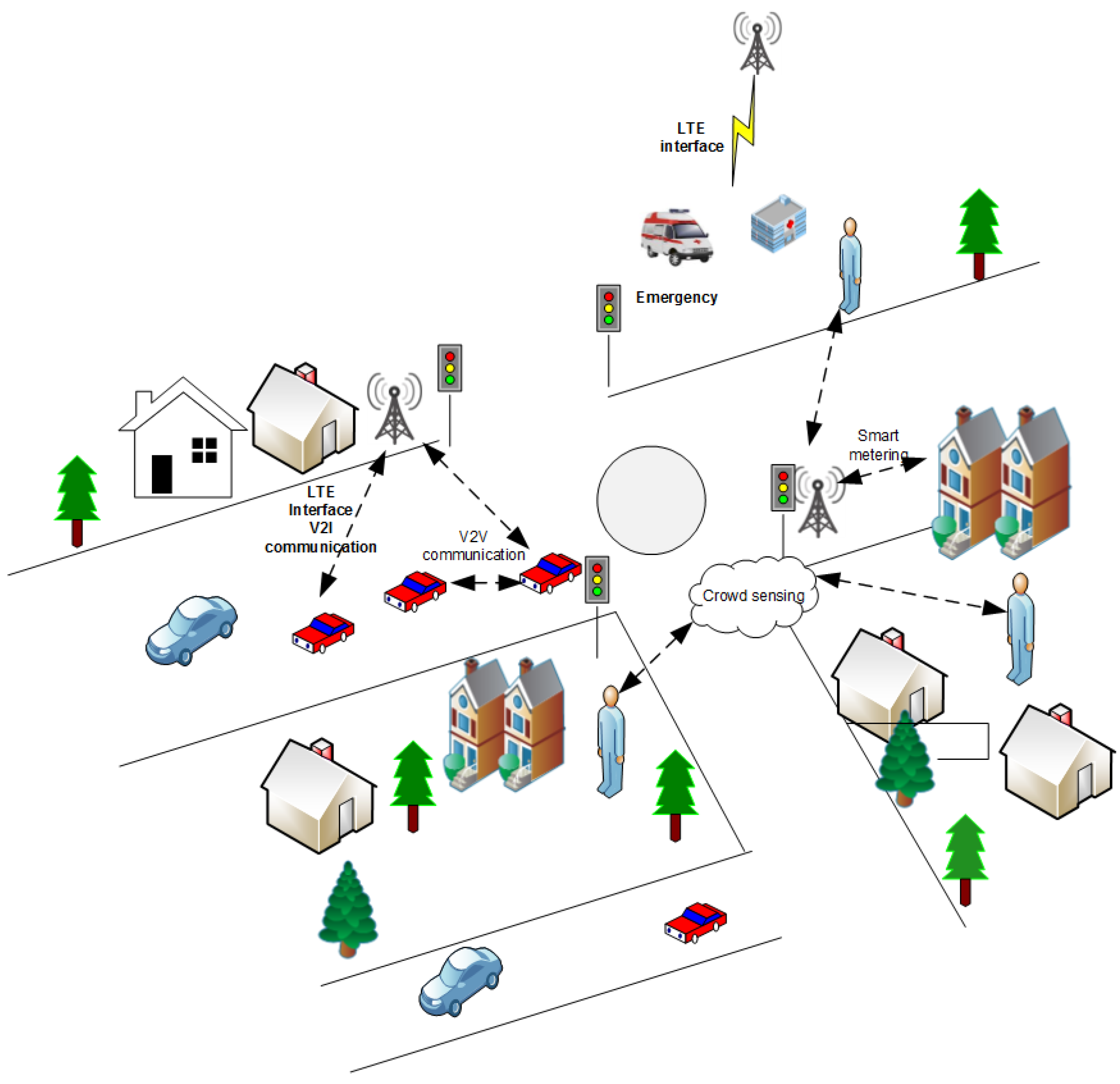
In many smart city application scenarios—from building monitoring and healthcare monitoring, through smart parking and smart city lighting, to crowd sensing and vehicular safety applications—a large number of smart devices send their messages to appropriate servers for further analysis and actions, as Figure 1 schematically shows. As monitoring and transmission oftentimes do not require human intervention, such communications are referred to as Machine-to-Machine (M2M) or Machine-Type Communications (MTC) [1]. Networks that support M2M traffic must provide broad coverage, but also message reliability and limited delay. In densely-populated urban areas, such requirements can be achieved through WiFi networks, but in sparsely-populated rural areas and along the highways, one must rely on cellular networks such as LTE/LTE-A (Long-Term Evolution and Long-Term Evolution-Advanced) [2].
In some M2M scenarios, messages arrive regularly with approximately constant inter-arrival times and thus can be transmitted using some kind of scheduled access; this is the case, for example, for healthcare applications, building monitoring and smart city lighting. In other cases such as crowd sensing and vehicular safety, messages arrive randomly and thus may be serviced through contention-based access. In both cases, messages are short, and typical interarrival periods are low when compared to other traffic such as video and data transmitted over LTE. As a result, M2M messages can be transmitted using LTE’s Physical Random Access Channel (PRACH), which was originally intended to be used for initial access or area tracking by a terminal (User Equipment (UE)) that is not connected to the base station (eNodeB), for uplink synchronization of a UE that is connected to eNodeB, when a connected UE has to transmit uplink data or to acknowledge received data or when a UE needs to perform a handoff to the target cell [2]. The LTE standard prescribes that PRACH access be performed using a four-way handshake, which is contention-based (the details of random access are presented further in Section 2 below). If PRACH is congested due to a large number of M2M and/or H2H terminals attempting access concurrently, the SINR observed at the receiver (i.e., eNodeB) may be reduced to the extent that messages cannot be detected, and consequently, many of the access attempts will fail; this is denoted as the outage condition. In the past several years, a number of techniques to improve the performance of M2M traffic by alleviating outage due to congestion have been suggested:
- UEs may be grouped into traffic classes for which random access may be delayed or temporarily blocked. This technique is known as access class barring (which is already supported for H2H calls) and extended access class barring [3].
- Differentiation among traffic classes can be achieved by allowing different backoff windows for different classes of UEs [4].
- Further differentiation among the classes can be achieved by allowing members of the traffic class to attempt access only in predefined time slots within specific LTE frames, using base station scheduling [5].
- The base station can apply a suitable polling scheme (also known as pull-based scheme) to differentiate between UEs. In this scheme, M2M terminals initiate random access only after being paged by the eNodeB [6].
- PRACH resource separation and dynamic PRACH resource allocation schemes allocate different PRACH resources such as preamble sequences and random access slots to different types of traffic (i.e., H2H and M2M) in a dynamic manner [7].
- Traffic classes can be differentiated by using different power levels rather than using power ramping based on the age of the attempt [8].
- Failed calls may be allocated a specific set of preambles to use for repeated access attempts [9].
Recently, an overlay network for M2M traffic was proposed that dedicates a portion of PRACH resources to M2M traffic [10]. The overlay network is based on the CSMA-CA mechanism similar to IEEE 802.15.4 [11] and allows M2M access to be completed without the four-way handshake. H2H traffic concurrently uses remaining resources and is coupled with M2M traffic through the SINR at the eNodeB. Further differentiation is possible using different and explicit power levels for M2M and H2H traffic [12].
However, this approach [10,12] does not address two important aspects of M2M communications. First, differentiation among different traffic classes in the M2M overlay network is needed. Second, SINR coupling between M2M and H2H traffic classes has been considered only at the packet reception level, but not at the level of listening to the medium during the CSMA-CA backoff process. This could produce incorrect durations of the backoff process and a too conservative estimate of the congestion at the overlay network.
In this work, we introduce priority differentiation in the overlay network by using the CSMA-CA similar to IEEE 802.15.6 [13] with modifications necessary to match the existing physical layer derived from PRACH. We model the medium access control algorithm including a model of imprecise listening outcome during the backoff process, which is shown to decrease the capacity of the overlay network to a non-negligible extent. We demonstrate the functionality and performance of our scheme using different schemes and bandwidths of PRACH, as well as PRACH design scenarios for micro- and macro-cells. Using an accurate characterization of noise and interference caused by other calls from the given cell, as well as from the surrounding cells (which is absent from other proposals), we show that the scheme is capable of achieving satisfactory performance, as well as sufficient differentiation between traffic classes. It is, thus, suitable for the massive Machine-Type Communications (mMTC) scenario—i.e., a large number of MTC devices with short messages and low arrival rates—which represents one of the major use cases for the development of 5G radio and network technology [14]. Furthermore, our scheme allows M2M terminals to actually transmit data during PRACH access, which in most cases should suffice given the short messages typical for M2M devices, whereas other schemes use random access to initiate a connection and send actual data only later, which increases message latency and leads to inefficient utilization of the available bandwidth.
The rest of the paper is organized as follows: In Section 2, we present the PRACH architecture and random access procedure. In Section 3, we present the M2M overlay network with the physical and MAC layer, preceded by a brief overview of earlier work on such overlays using different WLAN technologies. In Section 4, we present the random access model for H2H and PM2M traffic. The analytical model of PM2M with backoff error is discussed in Section 5. Performance evaluation of H2H and PM2M traffic (with and without the backoff error) is shown in Section 6. Finally, Section 7 concludes the paper.
2. PRACH Architecture and Random Access Procedure
The Physical Random Access Channel (PRACH) allows a UE to establish a connection with the base station (eNodeB) by sending a request to which the eNodeB will respond by scheduling appropriate resources for communications to and/or from the UE. Available bandwidth resources for LTE cell are divided in a time and frequency domain matrix. Time access is organized in frames that last 10 ms and that consist of 10 subframes with a duration of 1-ms each. Subframes can be divided into two 0.5-ms slots. In the frequency domain, resources are grouped in units of 12 OFDM subcarriers with a total bandwidth of 180 kHz. The basic access unit for either random or scheduled access is a Resource Block (RB), which consists of 12 subcarriers over one subframe. Cell bandwidth can be configured in frequency- or time-division duplex (i.e., FDD or TDD operation mode.
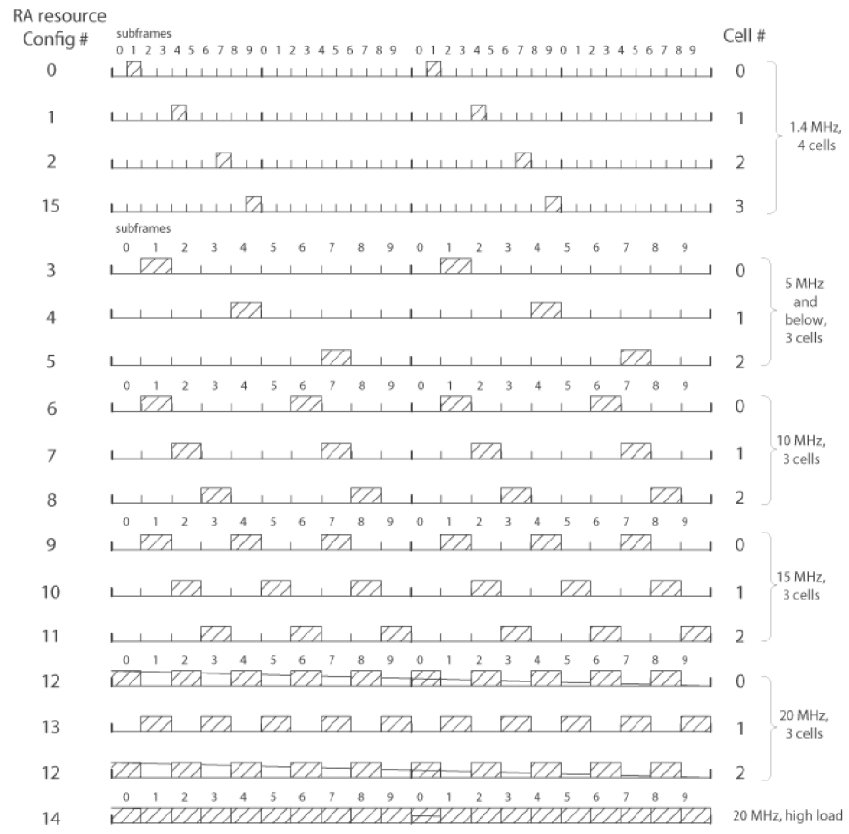
PRACH is carved out of the time and frequency domain matrix by dedicating a number of resource blocks in a number of consecutive LTE frames. The basic PRACH resource is composed of six resource blocks in frequency with a bandwidth of 1.080 MHz, for the duration of one subframe; higher traffic volume can be accommodated by allocating more resources, for a total of 16 configurations shown in Figure 2. For low traffic intensity and small system bandwidth, one PRACH resource per two frames may be sufficient (TDMA Configurations 0, 1, 2 and 15). As traffic increases, PRACH resources may be configured to occur once per frame (TDMA Configurations 3, 4 and 5), twice per frame (TDMA Configurations 6, 7 and 8) or even once every three subframes (TDMA Configurations 9, 10 and 11). These configurations avoid interference at a granularity of three neighbouring cells. However, higher traffic may require even more dense PRACH allocations, which brings the possibility of interference since the PRACH resource occurs on every second subframe (Configurations 12 and 13) or on every subframe in a frame (Configuration 14). In the discussions that follow, we will denote the number of PRACH subframes within the frame as configuration index , where means that there are k PRACH subframes in the frame.
Steps of the Random Access Procedure
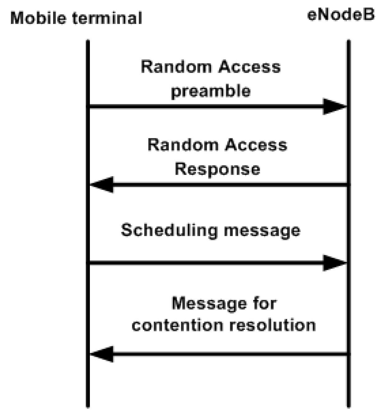
The UE that wishes to establish communication with eNodeB needs to the perform random access procedure on PRACH [15] using the four-way handshake (Figure 3), which consists of the following steps:
- Step 1:
- The terminal randomly selects the preamble from the available 54 preamble sequences and transmits it over PRACH to eNodeB.
- Step 2:
- The eNodeB transmits an RA Response (RAR) to the terminal through the physical downlink shared channel (PDSCH). RAR contains temporary Cell Radio Network Temporary Identifier (CRNTI) identity information. It also contains scheduling information for the third step.
- Step 3:
- Then, the terminal sends its CRNTI and scheduling information to eNodeB through the Physical Uplink Shared Channel (PUSCH) radio resources assigned in Step 2.
- Step 4:
- Finally, the eNodeB responds with the confirmation of the identity of the terminal and finishes the contention procedure.
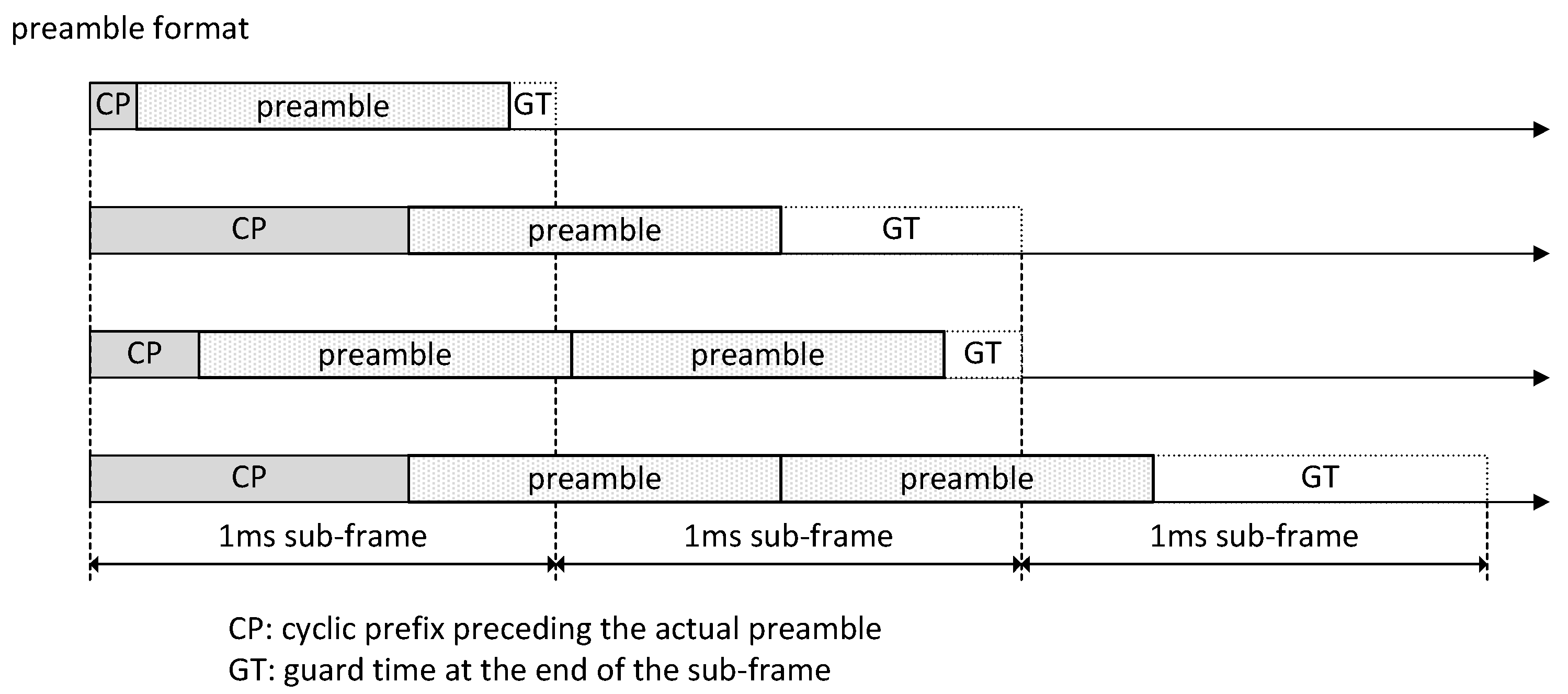
Preambles are mutually-orthogonal Zadoff–Chu (ZC) sequences; by default, each cell has a pool of preambles. A small number of preambles (typically, 10) is reserved for time critical actions like handoff, while the remaining 54 are available for random access. The duration of a preamble depends on the cell size since larger cells have higher signal attenuation and larger propagation delays. Signal attenuation can be countered by a longer preamble time (1600 s, as opposed to the default value of 800 s). Propagation delays can be countered by extending the time intervals. As a result, Preamble Format 0 fits in a single 1-ms subframe, Formats 1 and 2 fit into two consecutive subframes, while Format 3 fits into three consecutive subframes [2,15]. The structure of preamble formats is shown in Figure 4, and in the text that follows, we will refer to the format number as .
The rules for calculating preamble sequence length are based on optimizing the number of ZC sequences with respect to cross-correlation properties and minimizing interference from PUSCH in neighbouring cells [2,16,17]. For example, in a typical LTE system with a 5-MHz bandwidth, the bandwidth dedicated to the PRACH channel is MHz. For Format 0, a preamble of total length elements is transmitted within 800 s, which gives the preamble element rate of M elements per second.
Unfortunately, the first and third steps of handshaking are prone to collisions and the overload condition due to the limited number of preambles. The resulting low SINR value prevents completion of the RA handshake [10] in the case of high traffic volume, which is likely in the case of massive M2M access. In a nutshell, the use of the four-way handshaking procedure of LTE for massive network access is inefficient and leads to SINR outage at the eNodeB [2]. This has motivated our research efforts towards a PRACH overlay architecture.
3. PM2M Overlay Network over PRACH
3.1. Earlier Work on Overlays in LTE
In [18], an IEEE 802.15.4-based VANET was proposed for implementing the VANET Control Channel (CCH) in urban areas. IEEE 802.15.4 has a low power consumption feature, which is an advantage over IEEE 802.11p’s high power consumption. In [19,20,21], a comparative study between IEEE 802.11p and LTE aimed to evaluate their suitability for different vehicular applications and finding, using analytical and simulation modelling, that the latter has a distinct advantage over IEEE 802.11p-based VANET for transmission of safety messages was shown [22]. Other studies have shown that LTE supports mobility and provides higher network capacity compared with IEEE 802.11p [20]. However, LTE was found not to provide sufficient reliability in terms of safety messages transmitted over PRACH, as the network can easily become overloaded [21,23]. The main culprit is the four-way handshake, which for small safety messages limits the capacity and increases the latency [10]. Additionally, the data rate for VANET safety messages remains constant regardless of the distance to eNodeB and the closeness of congestion, while in IEEE 802.11p, it can be adaptively adjusted according to the channel quality [24].
Before the introduction of the IEEE 802.15.6 standard, IEEE 802.15.4 and Bluetooth were considered as feasible physical and MAC layer protocols for healthcare applications. In [25], the authors did a comparative study between the IEEE 802.15.4 and IEEE 802.15.6-based MAC protocols for healthcare systems. The study showed that IEEE 802.15.4 cannot reliably transmit real-time medical data because it does not support high data rate applications and priority among traffic classes. The simulation study showed that IEEE 802.15.4 is suitable only for applications that require a data rate below 40 kbps, while applications requiring higher data rates should use the IEEE 802.15.6-based network. In [26], it was shown that there is no interference when WiMAX or LTE are integrated with IEEE 802.15.6. To enlarge the radio coverage, the authors in [27] integrated IEEE 802.15.6 with LTE because they showed that existing architectures were not suitable for the scenarios of high mobility due to the channel quality fluctuation.
The performance of a healthcare system through interconnecting IEEE 802.15.6 with IEEE 802.11e-based WLAN for a medical information system was studied in [28]. The proposed architecture used the RTS/CTS mechanism for accessing the medium in the WLAN, which caused overload in the network and coexistence issues. That work also did not consider the presence of backoff error due to the interference in the physical layer while accessing the medium to transmit the packets. In [26], it was shown that there is no interference when WiMax or LTE are integrated with the IEEE 802.15.6 network. It was proposed in [27] that LTE supports reliable data transmission with high data rates for real-time health messages over large coverage areas.
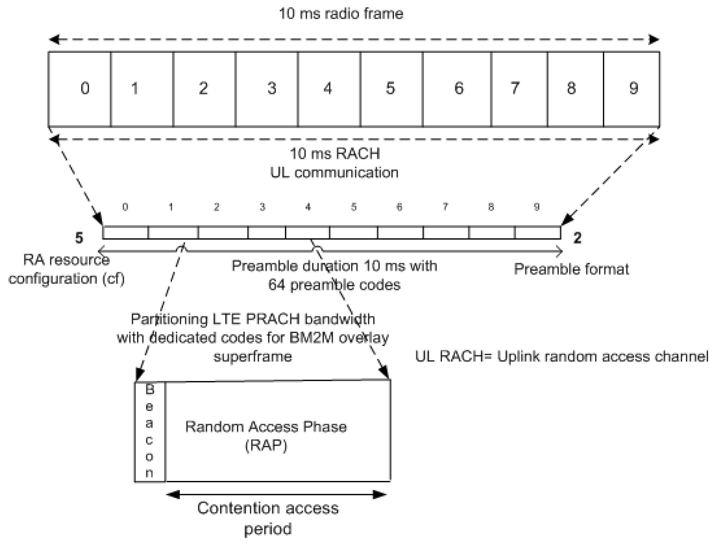
3.2. Superframe Structure of PM2M
The superframe structure of the proposed Priority-based Machine-to-Machine (PM2M) overlay network is shown in Figure 5. Time is organized in beacon-delineated superframes that start immediately after the reception of beacon; UEs send their messages in the CSMA-CA manner after completing the backoff procedure, as explained below. eNodeB has to acknowledge the message, otherwise the message will be retransmitted until the retransmission limit is reached. While H2H traffic will continue to follow the four-way handshake to access the network, the PM2M overlay network reduces four-way handshake to a simpler two-way one.
3.3. Physical and MAC Layer
The physical layer of the M2M overlay network is implemented by selecting of the 54 sequences available for contention-based access and dedicating them to M2M access. Data bits from the M2M stream are multiplexed on M2M preambles so that each sequence carries a single bit from each data byte. To transmit a single M2M data bit, preamble elements are used as a kind of ‘chipping’ sequence, the size of which affects the performance as SINR increases by . Higher SINR is needed for the detection of M2M data bits since an H2H preamble is detected based on the SINR over its entire duration, while only a portion of that duration is used by M2M packets.
Performance is also affected by the number of ZC codes dedicated to M2M, as these are bundled together so that each code carries bits of each user’s byte. The physical layer data rate is, then, , where R is the preamble element rate.
In this scheme, each PRACH resource holds a single PM2M superframe, which makes CSMA-CA access possible. For the Medium Access Control (MAC) layer, PM2M access is configured as a CSMA-CA overlay. The time for preamble transmission becomes the superframe time for the PM2M overlay network. We consider the IEEE 802.15.6 beacon mode with beacon period boundaries where at the beginning of every superframe, a beacon is transmitted on the medium. The superframe time after the beacon is divided into slots each containing 20 bits. The superframe is divided into an Access Phase (AP) and Random Access Phase 1 (RAP1); all other access phases allowed by the standard will have zero length. We do not use the RTS/CTS handshake, nor the four-way handshake of LTE, as they would easily overload the PRACH.
CSMA-CA access in the superframe resembles the one used in the beacon-enabled IEEE 802.15.6. In the CSMA-CA overlay, one backoff period has 20 sequence elements, i.e., s. To implement the overlay superframe, we use Preamble Format 2, where the preamble duration is 1.6 ms. Access in Format 2 is achieved by repeating the same preamble twice. Finally, to achieve a continuous superframe sequence without coordinated node sleeping, we assume configuration index .
3.4. Priority Mapping
IEEE 802.15.6 provides priorities through the Contention Window (CW) and Access Categories (AC). There are eight different ACs with different minimum and maximum CW values, which define User Priorities (UP) to access the medium, as shown in Table 1.
4. Modelling PRACH for H2H and PM2M Traffic
We now present the analytical model of random access, beginning with H2H terminals. Although the population of H2H terminals in a single LTE/LTE-A cell is large, they attempt random access occasionally and infrequently, which means that we may assume that H2H requests arrive according to a Poisson distribution. The mean arrival rate of H2H traffic can be calculated for a single PRACH resource as, , where is the LTE superframe time and determines the number of PRACH resource blocks per LTE frame.
LTE PRACH is overloaded by preamble transmissions with potential collisions and external interference caused by the random access in surrounding cells. To detect a signal successfully at the eNodeB, the Signal to Interference Noise Ratio (SINR) should exceed a certain threshold value as indicated in Figure 17.12 in [2]. For example, a threshold value of guarantees that the probability of preamble missed detection is smaller than and the probability of false alarm is less than for eNodeB. For H2H terminals, SINR is the ratio of preamble sequence energy over noise power density, for n H2H terminals concurrently performing access including initial and handoff requests. Assuming all transmissions use the same power level, the aforementioned ratio is:
where
- is the preamble sequence length in bits;
- W is the LTE PRACH bandwidth;
- R is the LTE PRACH preamble data rate;
- is the received signal power;
- is the power of external (Gaussian) interference;
- is the spectral density of white noise; and
- is the number of preambles that are always active for the PM2M overlay.
The ratio of the outer cell interference and received signal power of PRACH follows a Gaussian distribution with mean and variance denoted by and [10]. In the case of the threshold being exceeded, the overload condition occurs, and the preamble cannot be detected successfully. The probability of PRACH overload in the first handshake step is:
The PRACH overload for third handshake step for j concurrent H2H terminals is:
We assume that spectral efficiency in the third handshake step is the same as the first step, . The SINR threshold in this step is −5 dB because it is observed over a single bit. The ratio of the outer cell interference and received signal power of PRACH follows a Gaussian distribution with mean and variance denoted by and [10].
4.1. H2H PRACH Overload/Outage during Preamble Collision
LTE PRACH may experience the outage condition by having large access traffic, possibly with preamble collisions. To calculate the probability of PRACH outage/overload, we need to know the total Poisson arrival rate of access on a single PRACH resource block including new, returning and handoff calls, . The probability of n arrivals is:
For n H2H access attempts in PRACH resources, from overload Equation (2), we obtain the overload probability as:
where is a complementary error function,
Thus, the total overload probability for the first handshake step due to collision and interference is obtained by averaging the H2H load as:
where is a sufficiently large number.
For the third handshake step, the collision probability that H2H terminals collide when is:
where denotes the arrival rate of the third step L/L messages.
Now, to find the overload probability of the third handshake step, the overload probability of Equation (3) can be written for different values of bandwidth, spectral efficiency and SINR:
Thus, the overall PRACH overload probability for the third handshake step with preamble collision and inter-cell interference is:
4.2. PM2M Overload Calculation
The Bit Error Rate (BER) of the PM2M overlay depends on the interference caused by H2H traffic. We estimate the interference through the bit error rate BER experienced by PM2M traffic. To this end, we need to find the outage/overload probability of PM2M based on SINR requirements for PRACH, which can be expressed as:
where
- is the number of preamble elements;
- W is the LTE bandwidth;
- R is the LTE PRACH preamble data rate;
- is the received signal power;
- is the outer cell interference power; is the spectral density of white noise; and
- is the number of PM2M preamble codes that are always active.
The overload probability of PM2M data on each preamble can be derived analogously to Equations (2) and (5) as:
Then, the total PM2M overload probability can be obtained as:
Using the PM2M overload probability, we could approximate the BER as half of the overload:
5. Modelling the PM2M Backoff Procedure with Backoff Error
Let us now present the analytical model for the CSMA-CA backoff procedure. We model backoff errors that occur when a UE incorrectly estimates the state of the channel. Our modelling is based on elements developed in [13] with necessary modifications regarding the superframe structure and coupling with the physical layer. The physical layer influences clear channel assessment at MAC. The latter comes due to SINR, which depends on H2H traffic and preambles belonging to the physical layer of the overlay network.
We consider a single-hop PM2M overlay network with H2H terminals in a single LTE/LTE-A cell. The system works in the non-saturation condition where the packet queue does not always have a packet to transmit and each UE experiences an idle period when its queue is empty. The model consists of two three-dimensional Discrete Time Markov Chains (DTMCs). Note that the physical layer of our proposed architecture is different from that in [13] since our physical layer is implemented with dedicated preambles and we do not use RTS/CTS to avoid creating extra overload on the PRACH.
We consider two user priorities, , where Indices 0 and 1 refer to lower and higher priority traffic class, respectively. All the time scales are presented in slots and modified according to the LTE time scale. The backoff value of a node is distributed uniformly over the interval . has the minimum value of where . The maximum contention window value is , corresponding to the maximum number of retries . User priorities are differentiated according to the values of ; see Table 1. We assume that a packet is dropped if the number of unsuccessful attempts exceeds the retry limit R. Contention window values for a user priority node for the i-th backoff phase are calculated as follows:
- Initially, , where .
- The contention window value doubles when, , for , if i is an even number
- The contention window value increases uniformly when, , for , if i is an odd number.
We calculate the probability that neither the data nor the subsequent acknowledgement (ack) packet are corrupted by noise as:
where is the bit error rate caused by interference from H2H traffic and represent the data and acknowledgement size in slots.
In IEEE 802.15.6, during the CSMA-CA medium access, a UE senses the medium before decrementing the backoff counter. If the medium is sensed as busy, the node will freeze the backoff counter until the medium is sensed to be idle. The UE senses the status of the medium in backoff periods equivalent to 20-bit periods. Listening in each bit period may give an erroneous result with the probability . If more than half of the bits are wrong, the UE arrives at the wrong listening decision for a given backoff period with the probability of:
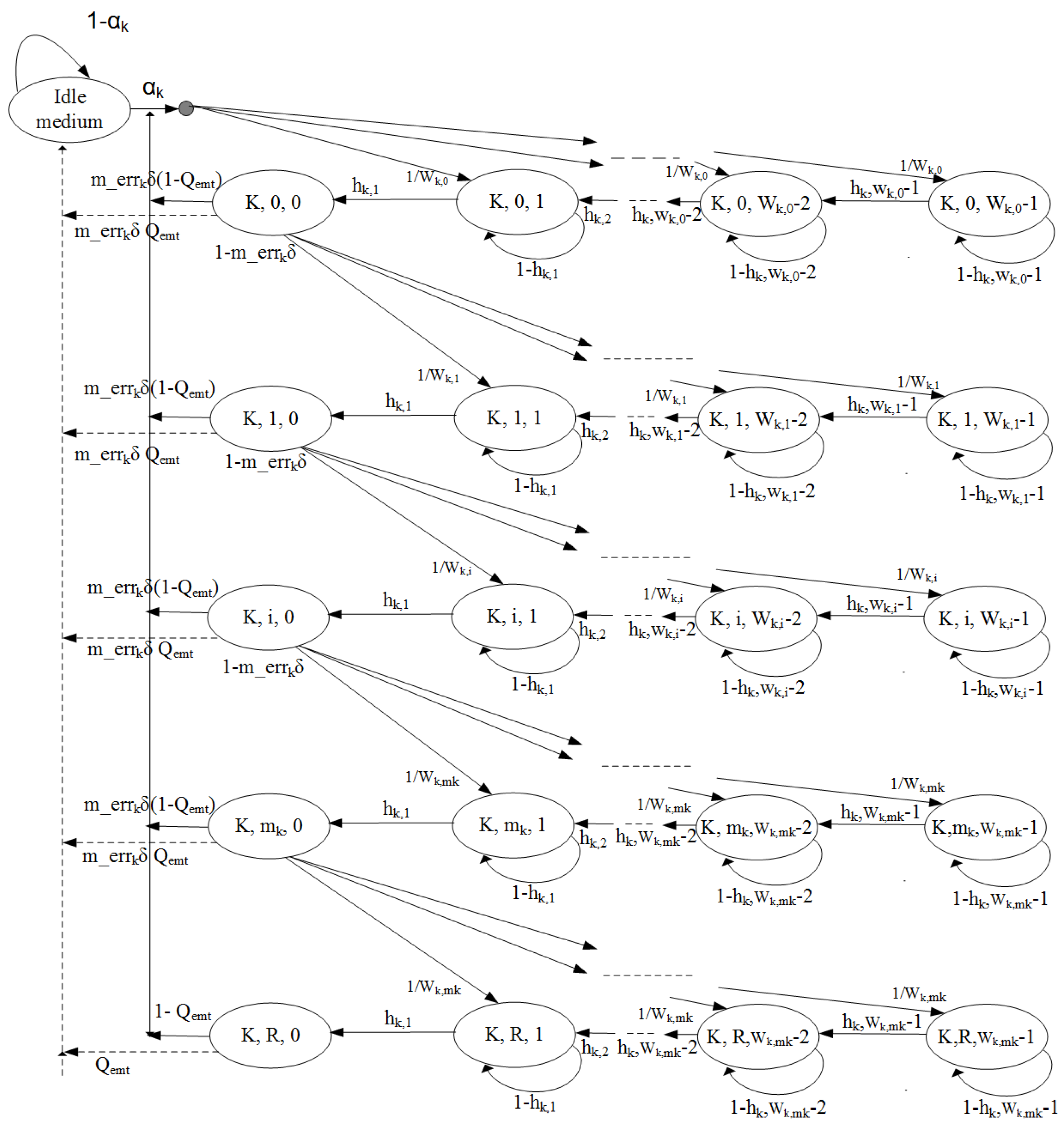
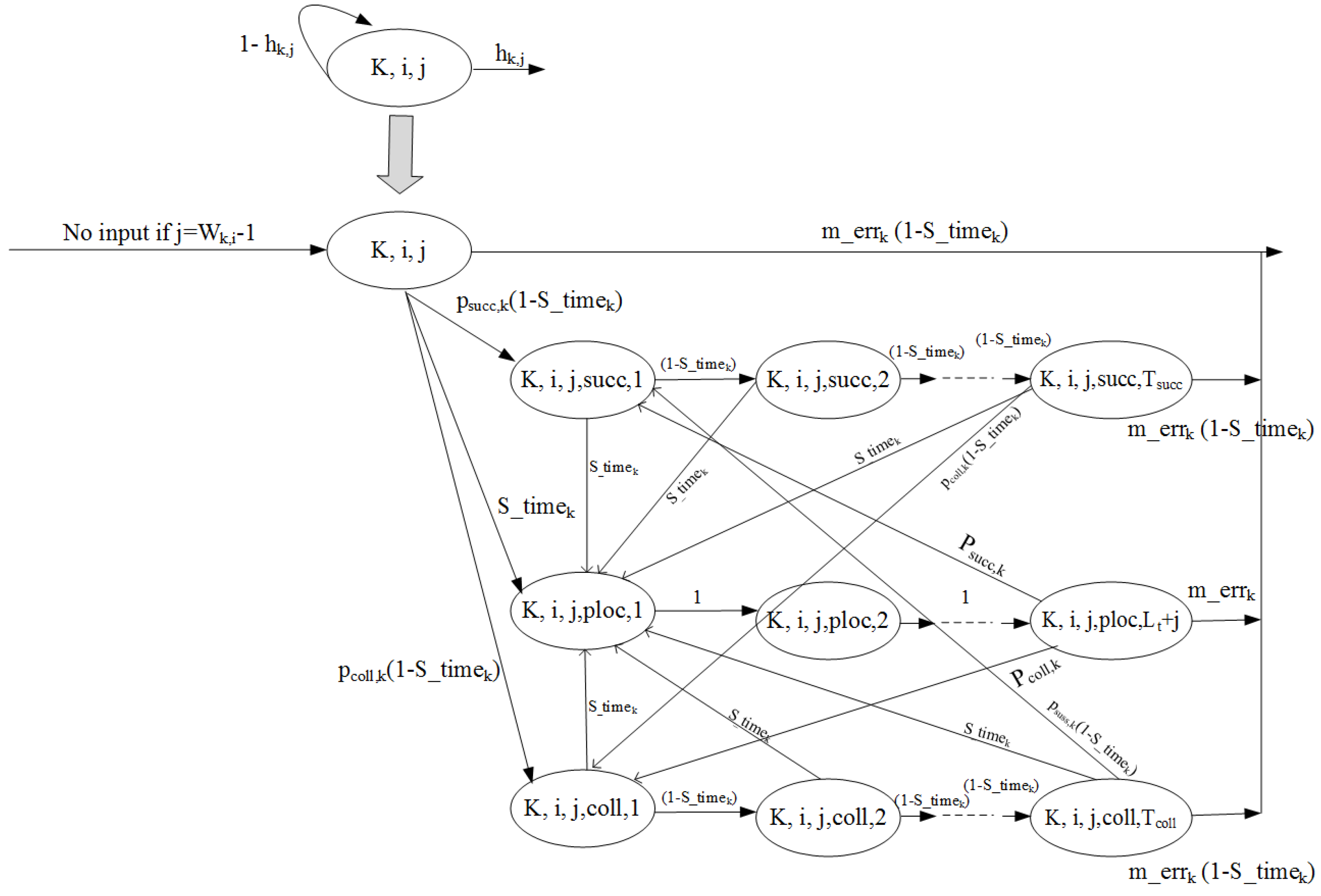
We develop a three-dimensional Discrete Time Markov Chain (DTMC) to model the backoff procedure of the CSMA-CA mechanism with backoff error only for two traffic classes and the Random Access Phase (RAP), as depicted in Figure 6. To calculate the average backoff time, we calculate all possible backoff phases during the CSMA-CA countdown and extend three-dimensional DTMCs to four-dimensional ones for all UPs, as shown in Figure 7.
The medium access probability of a node, where during RAP is calculated by solving the two dependent DTMCs derived by extending the framework from [13] with the probability of backoff error. The access probability is calculated only when the medium is idle and nodes are competing to get access. The incorrect idle medium probability in CSMA slots where all nodes with priority i perform access is:
and the probability that the medium is busy is:
Then, we evaluate the probability of the medium being idle as observed by UE of class during the backoff countdown (which means that other nodes do not access the medium during the current RAP) as:
During a given backoff countdown, there is a possibility that there is not enough time in the superframe (RAP) to complete the countdown and the transmission. The probability of this event is:
where
- = is the successful transmission time in slots;
- = is the approximate mean backoff counter value; and
- = is the unsuccessful transmission time.
In all cases, SIFS refers to short interframe space [11].
Now, we have to calculate the probability that the backoff counter value of a node will be unfrozen (i.e., decremented) for :
The indices of state probabilities of the Markov chain as shown in Figure 6 are , and . The medium access probability is calculated as .
We have to calculate the zeroth backoff phase, which depends on the probability of the CSMA slot being in the idle state, the probability that the queue is empty due to successful transmission or dropped because of the exceeded retry limit. In our model, we adopt the expression for the probability of the queue being empty from [13]. Then, the probability of being in the idle state may also refer to the wrong medium status in the presence of backoff error. Assuming that the probability of the data frame arrival during the interval between two successive Markov points is denoted as , the probability of the idle state is calculated as:
Thus, the sum of all DTMC states belonging of the zeroth backoff phase for traffic class k is:
The normalization condition for DTMCs of each class requires that the sum of all the state probabilities is one. By solving the system of equations belonging to the DTMC of each traffic class and coupling the equation for the behaviour of medium, we calculate the medium access probability for each traffic class with backoff error, , , during RAP as:
During the CSMA-CA mechanism when a node tries to get access to the medium, it has to backoff and lock the backoff counter if the channel is busy due to a transmission by another node, be it ultimately successful or not; or there is not enough time in the current superframe to complete the frame transmission.
The node unlocks the backoff counter again when the channel is idle for the SIFS period within the superframe time, and the current superframe has enough time to complete the frame transaction.
All of the above conditions work fine in the absence of backoff error. However, in the presence of backoff error, the node could decide that the medium is idle and unlock the backoff counter when the medium is actually busy, which could lead to excessive collisions in the overlay network. Alternatively, the node may freeze the backoff counter when it should not; this leads to longer backoffs and possibly to relegating a transmission to the next superframe.
We added the backoff error in the DTMC for the backoff procedure for traffic class k, as shown in Figure 7, and calculated the Probability Generating Functions (PGFs) of times for the important phases:
- , the time period between the locking and unlocking of the backoff counter due to successful transmission by another node.
- , the duration of unsuccessful transmission.
- , the time between locking and unlocking when there is not enough time for completing a packet transmission.
All of the above conditions are modelled for the RAP access phase with two traffic classes , with being the backoff counter value for the locked condition. We calculate the PGFs for the three periods stated above as:
where the parameters used in the derivations are as follows:
- is the probability that there is not enough time to complete a frame transaction in the current RAP;
- is the successful transmission time in slots;
- is the unsuccessful transmission time in slots;
- is the probability of locking the backoff counter due to successful transmission by others;
- is the probability of locking the backoff counter due to unsuccessful transmission by others; and
- is the number of CSMA slots when the backoff counter must be locked due to insufficient time for completing the transaction.
All of the above equations are solved to compute the values of unknown variables and model the duration of periods when the backoff counter is locked on the transition probabilities of the Markov chain with backoff error. Then, we proceed to find the mean number of backoff attempts in the presence of the backoff evaluation error, which, for traffic class k, has the probability .
The duration of the backoff process has a truncated geometric distribution with respect to the number of backoff phases, and we need to find the scaling factor, which corresponds to the probability that the backoff process does not complete within R attempts:
which gives:
Then, the mean number of backoff attempts () for the traffic class node before a successful access to the medium is:
6. Performance Evaluation
6.1. Performance of H2H Traffic in the Presence of the Overlay Network
We consider the LTE cells with a mix of H2H and M2M traffic, using the PRACH and PM2M overlay parameters given in Table 2.
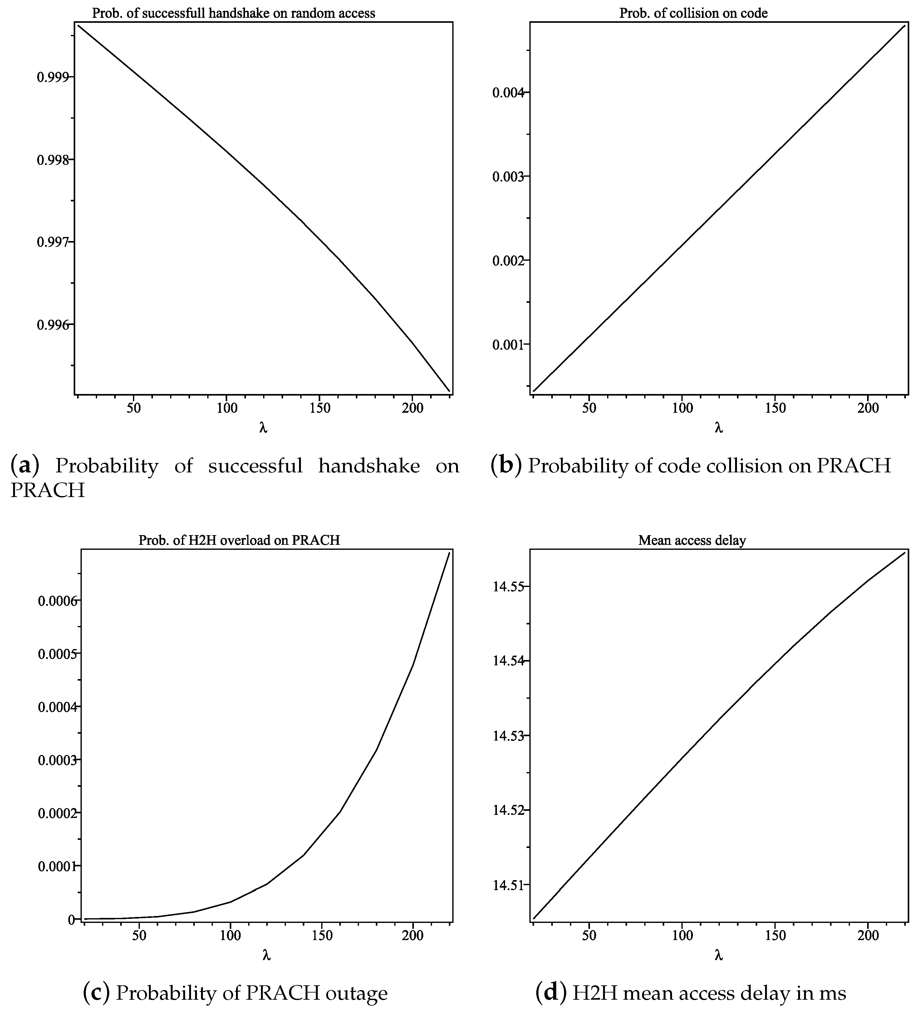
We first evaluate the performance of H2H traffic in the presence of PM2M overlay. The H2H request arrival rate was varied between 20 and 220 requests per second. Figure 8a shows the H2H probability of success, which remains within 99% up to 220 H2H calls/s. The collision probability shown in Figure 8b is only , which validates the probability of success. The presence of the overlay network is not overloading the cell with respect to H2H traffic, as shown in Figure 8c, where we observe that, for the H2H arrival rate up to 220 calls/s, the overload probability for H2H traffic is only , which is very low indeed. The mean access delay (Figure 8d) is essentially flat, with only a slight increase from ms– ms in the observed range. Note that these performance limits would apply to M2M devices in case they use regular LTE access on PRACH: in other words, the random access procedure on PRACH is able to accommodate only about 220 calls per second, be they posted by H2H or M2M users.
6.2. Performance of the PM2M Overlay Network without Backoff Error
We evaluate the performance of the PM2M overlay network for two traffic classes and for the contention-based RAP, with and without the backoff error, for H2H traffic intensity set to 100 calls/s. We consider the non-saturation condition, which means that the UE buffer will not always have a data frame to transmit. We assume that the data packet size is 30 bytes, including MAC headers of 10 bytes (where the cell and node ID should be) and the remaining 20 bytes used for MAC data.
We first investigate the capacity of the PM2M overlay network on PRACH by neglecting the error in clear channel assessment. The packet arrival rate per M2M node was set in the range between 0.4 and two packets/s, while the number of PM2M nodes was varied between 300 and 1560. The upper bound for the number of nodes was selected so as to capture reasonable decline in transmission success probability.
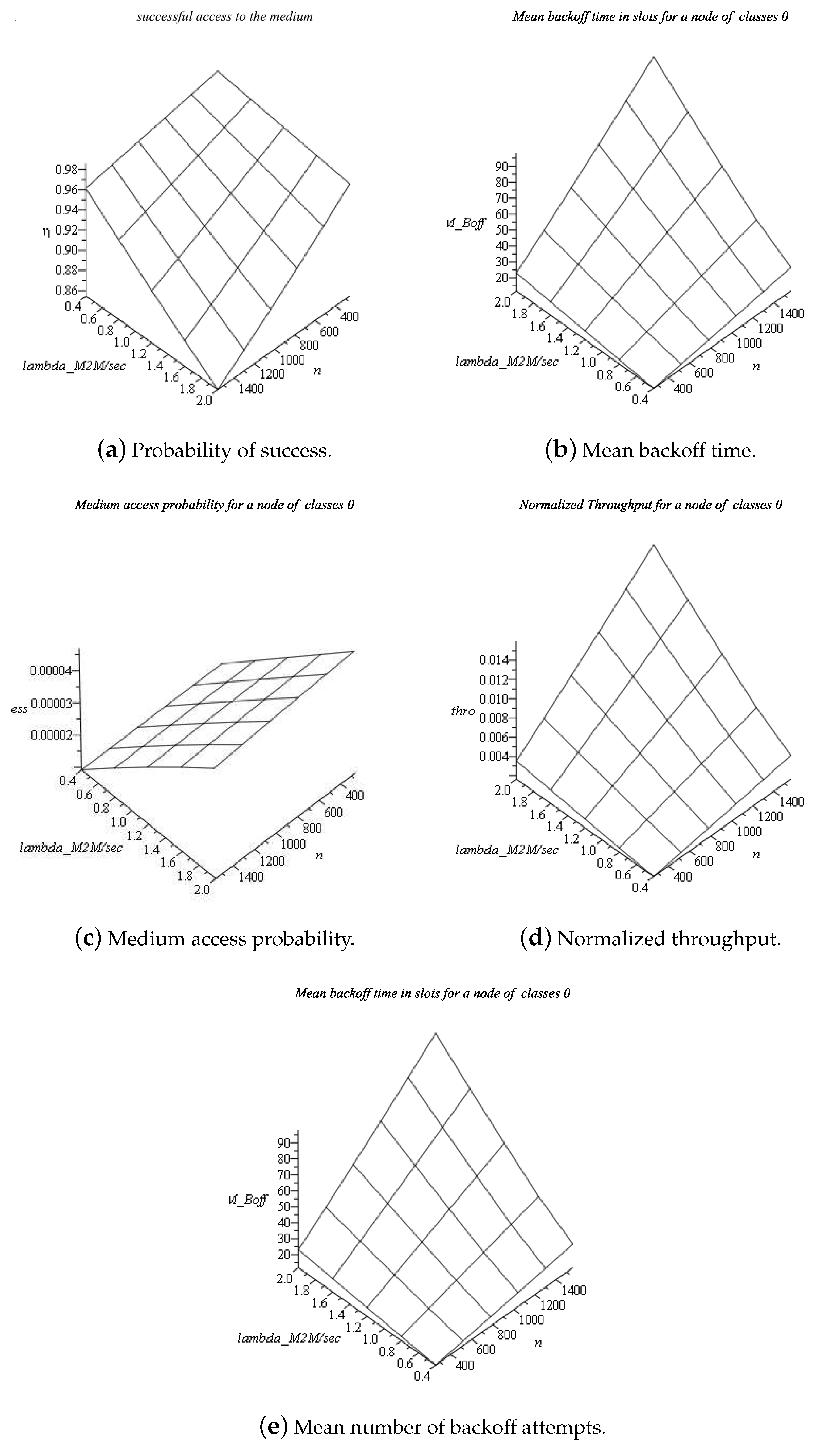
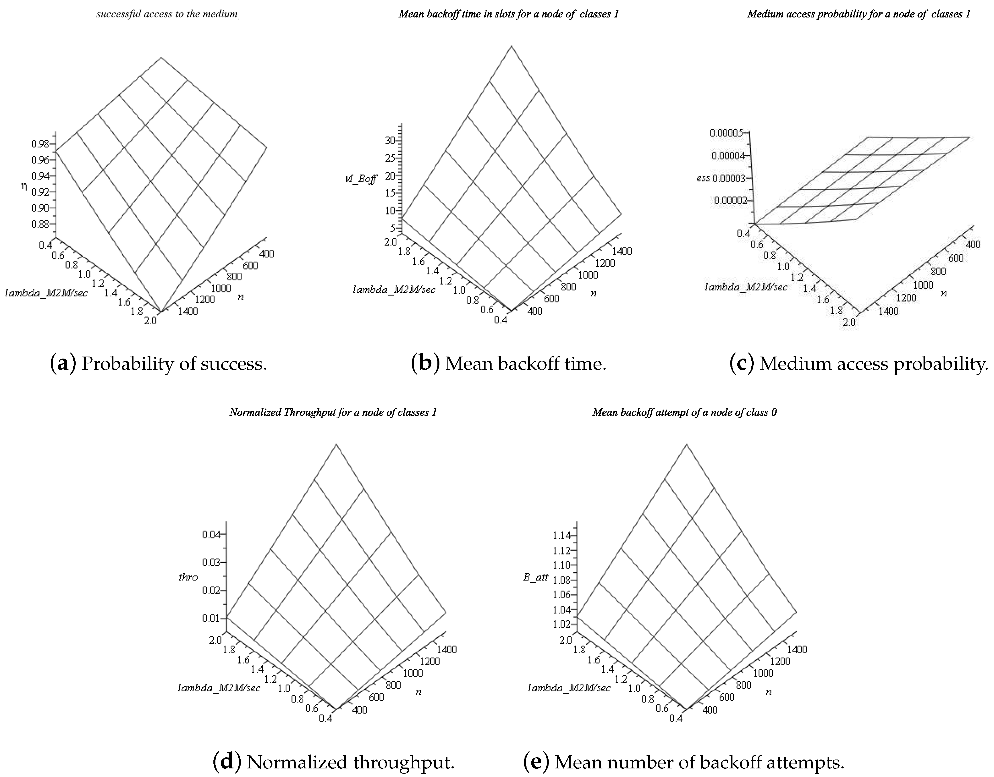
Figure 9a and Figure 10a show the probability of successful packet transmission for Traffic Classes 0 and 1. We notice that Traffic Class 1 achieves a 5% higher success probability than Traffic Class 0 for 1560 nodes. The mean backoff time for Classes 0 and 1, for 1560 nodes, was 98 and 35 backoff periods, respectively, as shown in Figure 9b and Figure 10b. This is reasonable since lower the priority traffic class with a higher contention window value has to backoff for a longer period of time than the higher priority class with shorter contention window. Medium access probabilities are shown in Figure 9c and Figure 10c. We notice that Traffic Class 1 has up to a 15% higher access probability.
We calculate the normalized throughput for each node, which was defined as the fraction of time in which the channel is used to transmit the frames’ payload. Figure 9d and Figure 10d show that the throughput of is almost three-times higher than for 1560 PM2M nodes and the highest data arrival rate. The mean number of backoff attempts is shown in Figure 9e and Figure 10e for Traffic Classes 0 and 1, respectively; again, we note the slight disadvantage of Traffic Class 0 with respect to Class 1.
6.3. Performance of the PM2M Overlay with Backoff Error
We evaluate the performance of PM2M with backoff error for both traffic classes under the same conditions as in the previous experiment, except that the number of nodes was ranging between 300 and 1320. As before, these values were chose to result in the decrease of the probability of successful access to the medium in the range similar to the case without backoff error, as considered in the previous subsection.
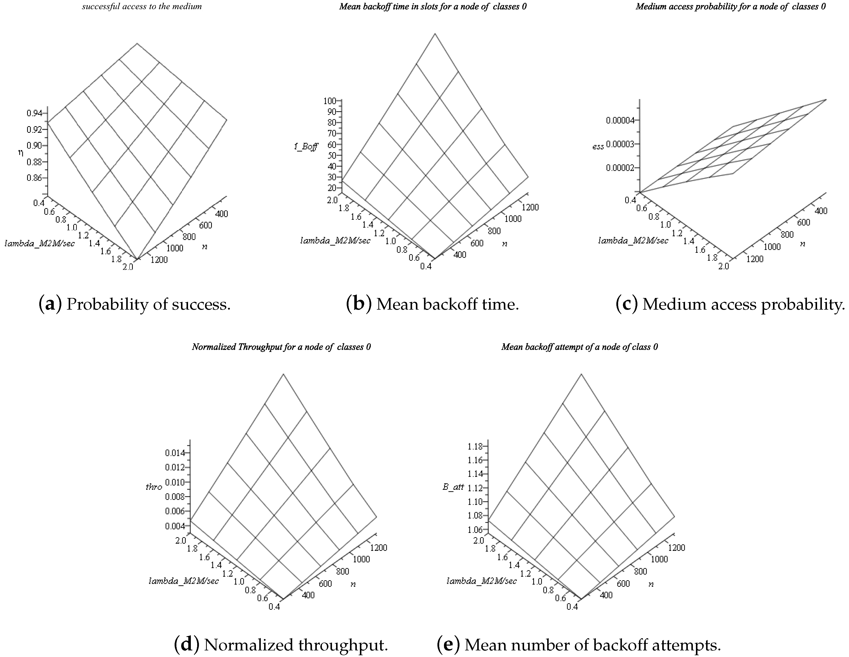
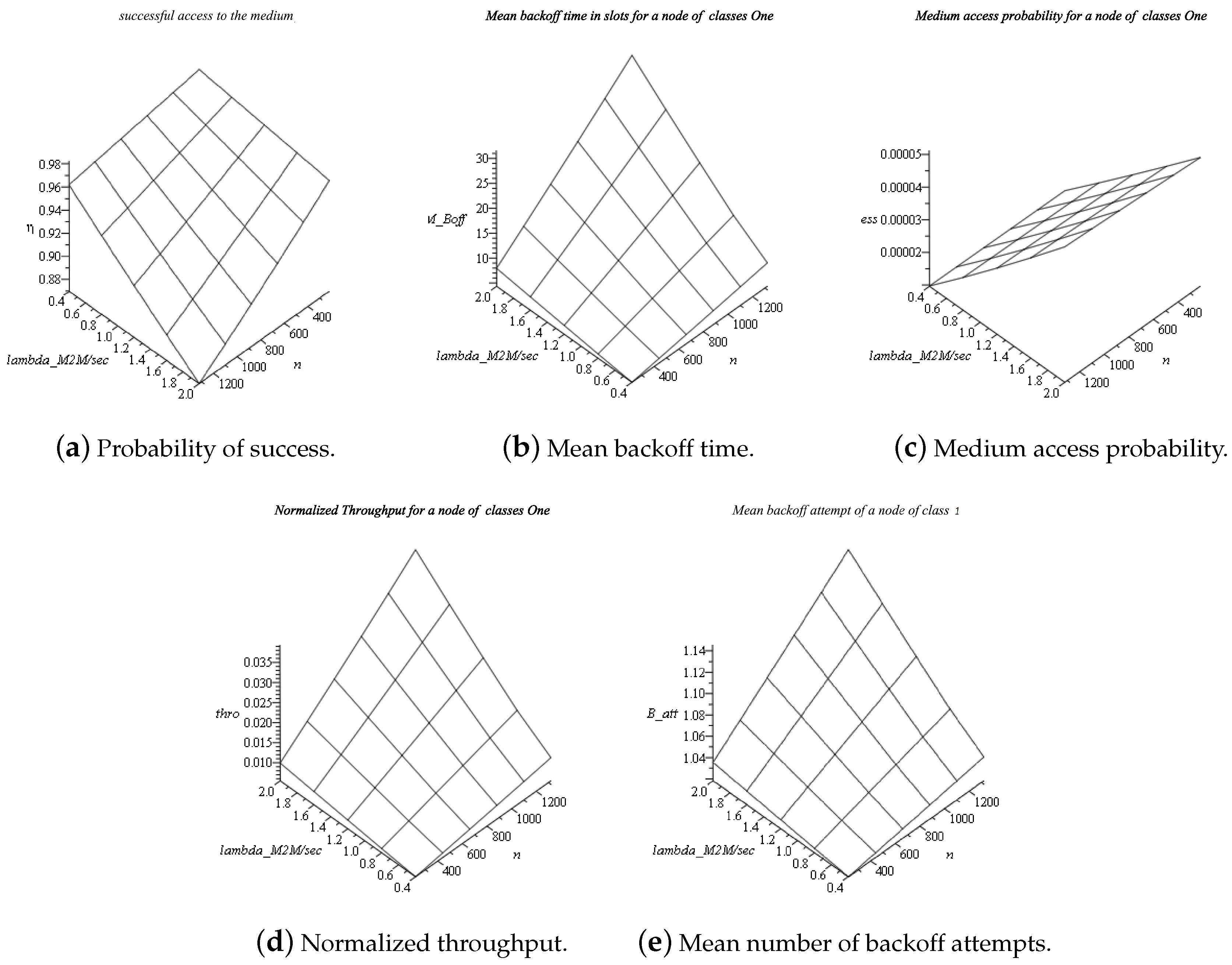
We found that we can accommodate up to about 1320 nodes for each traffic class in the same range of transmission success probability, which represents a 12% decrease of overlay network capacity. The transmission success probability for 1320 nodes and a packet arrival rate of two packets per second is close to and for Traffic Classes 0 and 1, respectively. The mean number of backoff periods in slots for Classes 0 and 1, shown in Figure 11b and Figure 12b, reaches 33 slots and 100 slots, respectively, under the highest load. The medium access probability (Figure 11c and Figure 12c) is about 10– lower for class than for the higher priority class . Figure 12d shows that the throughput of is almost three-times higher than (Figure 11d) under the highest load. Regarding the mean number of backoff attempts, Figure 11e shows that lower traffic class has to perform slightly more backoff attempts than higher priority traffic class (Figure 12e), as we expected with the presence of backoff error.
6.4. Discussion
It may seem that 1320 and 1560 M2M calls per second, obtained through the use of the PM2M overlay, are not that impressive a performance limit. However, it is known that there are “major difficulties in carrying the M2M traffic of more than 2000 UEs with an acceptable success ratio, even when all the 64 available preambles are dedicated TO M2M contention-based access” [29]. Improvements are reported when more preambles are used, up to 500 in [29], even though this is highly unrealistic. Namely, ZC sequences are mutually orthogonal, but they nonetheless cause interference with each other and decrease the achievable SINR. An increased number of preambles thus leads to increased error probability and degraded performance.
On the contrary, the PM2M overlay described here achieves this level of performance by using only eight out of 54 available ZC preambles, as explained in Section 3.3, which leaves the remaining 46 free for use with H2H traffic (10 preambles are set aside for handoff H2H calls); when 16 preambles are used, our CSMA overlay scheme can accommodate up to 2000 devices [12], which clearly shows its superiority over plain LTE random access for M2M calls.
A different scheme has been recently proposed that tries to resolve collisions and, presumably, improve performance by reassigning a subset of available preambles to calls that failed an access attempt [9]. However, they use a simplified error calculation based on slotted ALOHA, which does not account for interference caused by simultaneous random access attempts and/or other channels in the neighbouring cells. Moreover, their scheme requires modification of PRACH handling for M2M traffic, as all M2M nodes are required to listen to eNodeB announcements through which the subset of preambles used for repeated access is publicized, as it changes from one PRACH resource to the next one.
Unlike those schemes, our analysis uses the SINR calculation given in [2], which explicitly models the interference from other random access attempts both in the given and surrounding cells, which allows for more accurate and more realistic results. Furthermore, we model the impact of errors made during the medium sensing process, which no other scheme takes into account.
Finally, we note that all other schemes use random access just to initiate connection and obtain resources, as is common for H2H calls, and the actual data are sent later. In contrast, our scheme allows short messages typical for M2M devices to be actually transmitted during random access, which would lead to reduced latency and improved performance.
7. Conclusions
In this work, we have presented an IEEE 802.15.6-based overlay network that allows the LTE network to support massive M2M traffic with priorities over PRACH. The PM2M overlay operates by dedicating a number of available preambles to the physical layer of the overlay network; the remaining preambles can be used for LTE-prescribed random access by regular LTE UEs. We have modelled the performance of the overlay, as well as the mutual interference of H2H and PM2M traffic when both are present in the LTE cell and the performance of the PM2M overlay with and without the errors in the clear channel sense performed during the backoff countdown. Our results indicate, first, that the H2H traffic still enjoys fair access to the PRACH despite the presence of the PM2M overlay. Second, the PM2M overlay is capable of accommodating up to about 1500 M2M devices in a single cell with default LTE capacity. Third, the backoff error reduces this capacity by about 12% compared to the case with perfect channel sensing. In both cases, the PM2M overlay is capable of providing sufficient differentiation between low- and high-priority traffic classes given the backoff period. Our results show that including backoff error decreases overlay capacity by approximately 12% compared to the perfect clear channel assessment. We have also evaluated priority differentiation in the overlay network using different sizes of backoff windows. Therefore, we could consider a higher priority traffic class for more critical mMTC applications, such as vehicular safety, and a lower priority traffic class for applications with less stringent requirements, such as crowd sensing, thus making it suitable for a wide range of smart city applications.
Author Contributions
J.M. did the conceptualization and designed the methodology. N.K. did the investigation and adapted the methodology under the supervision of J.M. Validation was performed by J.M. and V.B.M. Original draft was written by N.K., and subsequently reviewed and edited by J.M. and V.B.M.
Funding
This research was funded by National Science and Engineering Research Council of Canada (NSERC) through Discovery Grant program.
Conflicts of Interest
The authors declare no conflict of interest. The founding sponsors had no role in the design of the study; in the collection, analyses, or interpretation of data; in the writing of the manuscript, and in the decision to publish the results.
References
- Mišić, V.B.; Mišić, J. (Eds.) Machine-to-Machine Communications—Architectures, Technology, Standards, and Applications; CRC Press: Boca Raton, FL, USA, 2014. [Google Scholar]
- Sesia, S.; Toufik, I.; Baker, M. LTE, the UMTS Long Term Evolution: From Theory to Practice; John Wiley & Sons: Hoboken, NJ, USA, 2009. [Google Scholar]
- Lien, S.Y.; Liau, T.H.; Kao, C.Y.; Chen, K.C. Cooperative access class barring for machine-to-machine communications. IEEE Trans. Wirel. Commun. 2012, 11, 27–32. [Google Scholar] [CrossRef]
- Cheng, J.P.; Lee, C.; Lin, T. Prioritized Random Access with Dynamic Access Barring for RAN Overload in 3GPP LTE-A Networks. In Proceedings of the 2011 IEEE GLOBECOM Workshops (GC Wkshps), Houston, TX, USA, 5–9 December 2011; pp. 368–372. [Google Scholar]
- Wu, H.; Zhu, C.; La, R.; Liu, X.; Zhang, Y. FASA: Accelerated S-ALOHA Using Access History for Event-Driven M2M Communications. IEEE/ACM Trans. Netw. 2013, 21, 1904–1917. [Google Scholar] [CrossRef]
- 3GPP. 3GPP TS 37.868 V11.0. Study on RAN Improvements for Machine Type Communications; Technical Report; 3GPP: Valbonne, France, 2011. [Google Scholar]
- Lo, A.; Law, Y.W.; Jacobsson, M.; Kucharzak, M. Enhanced LTE-Advanced Random-Access Mechanism for Massive Machine-to-Machine (M2M) Communications. In Proceedings of the 27th Meeting of Wireless World Research Forum (WWRF), Düsseldorf, Germany, 23–25 October 2011. [Google Scholar]
- Mišić, J.; Mišić, V.B.; Ali, M.Z. Explicit power ramping during random access in LTE/LTE-A. In Proceedings of the IEEE Wireless Communications and Networking Conference, San Francisco, CA, USA, 19–22 March 2017. [Google Scholar]
- Ali, M.S.; Hossain, E.; Kim, D.I. LTE/LTE-A random access for massive machine-type communications in smart cities. IEEE Commun. Mag. 2017, 55, 76–83. [Google Scholar] [CrossRef]
- Mišić, J.; Mišić, V.; Khan, N. Sharing It My Way: Efficient M2M Access in LTE/LTE-A Networks. IEEE Trans. Veh. Technol. 2017, 66, 696–709. [Google Scholar]
- Mišić, J.; Mišić, V. Wireless Personal Area Networks—Performance, Interconnections and Security with IEEE 802.15.4; John Wiley and Sons: Hoboken, NJ, USA, 2008. [Google Scholar]
- Mišić, J.; Mišić, V. Adapting LTE/LTE-A to M2M and D2D Communications. IEEE Netw. 2017, 31, 63–69. [Google Scholar] [CrossRef]
- Rashwand, S.; Mišić, J.; Mišić, V.B. Analysis of CSMA/CA Mechanism of IEEE 802.15.6 under Non-Saturation Regime. IEEE Trans. Parallel Distrib. Syst. 2016, 27, 1279–1288. [Google Scholar] [CrossRef]
- Boccardi, F.; Heath, R.W.; Lozano, A.; Marzetta, T.L.; Popovski, P. Five disruptive technology directions for 5G. IEEE Commun. Mag. 2014, 52, 74–80. [Google Scholar] [CrossRef] [Green Version]
- 3GPP. 3GPP TS 36.321 V10.1.0. Medium Access Control (MAC) Protocol Specifications; Technical Report; 3GPP: Valbonne, France, 2011. [Google Scholar]
- 3GPP. 3GPP TS 36.331 V10.1.0. Radio Resource Specifications; Technical Report; 3GPP: Valbonne, France, 2011. [Google Scholar]
- Dahlman, E.; Parkval, S.; Skold, J. 4G: LTE/LTE-Advanced for Mobile Broadband; Academic Press: Cambridge, MA, USA, 2011. [Google Scholar]
- Wan, J.; Li, D.; Zou, C.; Zhou, K. M2M Communications for Smart City: An Event-Based Architecture. In Proceedings of the 2012 IEEE 12th International Conference on Computer and Information Technology, Chengdu, China, 27–29 October 2012; pp. 895–900. [Google Scholar] [CrossRef]
- Araniti, G.; Campolo, C.; Condoluci, M.; Iera, A.; Molinaro, A. LTE for vehicular networking: A survey. IEEE Commun. Mag. 2013, 51, 148–157. [Google Scholar] [CrossRef]
- Mir, Z.H.; Filali, F. LTE and IEEE 802.11p for vehicular networking: A performance evaluation. EURASIP J. Wirel. Commun. Netw. 2014, 1, 89. [Google Scholar]
- Vinel, A. 3GPP LTE Versus IEEE 802.11p/WAVE: Which Technology is Able to Support Cooperative Vehicular Safety Applications? IEEE Wirel. Commun. Lett. 2012, 1, 125–128. [Google Scholar] [CrossRef] [Green Version]
- Arora, A.; Rakesh, N.; Mishra, K.K. Analysis of Safety Applications in VANET for LTE Based Network. In Networking Communication and Data Knowledge Engineering; Perez, G.M.E., Ed.; Springer: Singapore, 2018; pp. 141–154. [Google Scholar]
- Abid, H.; Chung, T.C.; Lee, S.; Qaisar, S. Performance Analysis of LTE Smartphones-Based Vehicle-to-Infrastructure Communication. In Proceedings of the 2012 9th International Conference on Ubiquitous Intelligence and Computing and 9th International Conference on Autonomic and Trusted Computing, Fukuoka, Japan, 4–7 September 2012; pp. 72–78. [Google Scholar]
- Campolo, C.; Molinaro, A. Data rate selection in WBSS-based IEEE 802.11p WAVE vehicular ad hoc networks. In Proceedings of the 2010 7th International Symposium on Communication Systems, Networks and Digital Signal Processing, Newcastle upon Tyne, UK, 21–23 July 2010; pp. 412–416. [Google Scholar]
- Zaouiat, C.; Latif, A. Performances Comparison of IEEE 802.15. 6 and IEEE 802.15. 4. IJACSA Int. J. Adv. Comput. Sci. Appl. 2017, 8, 461–467. [Google Scholar]
- Hu, L.; Dung, O.M.; Liu, Q.; Han, T.; Sun, Y. Integration of Wireless Body Area Networks (WBANs) and WAN, WiMAX and LTE. KSII Trans. Internet Inf. Syst. 2013, 7, 980–997. [Google Scholar]
- Castel, T.; Lemey, S.; Agneessens, S.; Torre, P.V.; Rogier, H.; Oestges, C. LTE as a potential standard for public safety indoor body-to-body networks. In Proceedings of the 2015 IEEE Symposium on Communications and Vehicular Technology in the Benelux (SCVT), Luxembourg, 24 November 2015; pp. 1–6. [Google Scholar]
- Rashwand, S. Efficient Wireless Communication in Healthcare Systems; Design and Performance Evaluation. Ph.D. Thesis, The University of Manitoba, Winnipeg, MB, Canada, 2012. [Google Scholar]
- Cherkaoui, S.; Keskes, I.; Rivano, H.; Stanica, R. LTE-A random access channel capacity evaluation for M2M communications. In Proceedings of the 8th IFIP Wireless Days (WD 2016), Toulouse, France, 23–25 March 2016. [Google Scholar]
Figure 1.
M2M communications for smart city scenarios through LTE.

Figure 2.
PRACH resource configurations, after [2].
Figure 2.
PRACH resource configurations, after [2].

Figure 3.
Four-way handshake between UE and eNodeB (after [15]).
Figure 3.
Four-way handshake between UE and eNodeB (after [15]).

Figure 4.
Different preamble formats.

Figure 5.
LTE and Priority-based Machine-to-Machine (PM2M) overlay superframe with PF = 2 (2-ms subframe).
Figure 5.
LTE and Priority-based Machine-to-Machine (PM2M) overlay superframe with PF = 2 (2-ms subframe).

Figure 6.
Markov chain for , modified from [13].
Figure 6.
Markov chain for , modified from [13].

Figure 7.
Extended Markov chain for modified from [13].
Figure 7.
Extended Markov chain for modified from [13].

Figure 8.
Performance of H2H traffic for PF = 2, cf = 5.

Figure 9.
Performance of the PM2M overlay for Traffic Class 0 without backoff error.

Figure 10.
Performance of the PM2M overlay for Traffic Class 1 without backoff error.

Figure 11.
Performance of the PM2M overlay for traffic class TC0 with backoff error.

Figure 12.
Performance of the PM2M overlay for traffic class TC1 with backoff error.


Table 1.
IEEE 802.15.6 Access Categories (AC) with User Priorities (UP) and Contention Window (CW) values.
Table 1.
IEEE 802.15.6 Access Categories (AC) with User Priorities (UP) and Contention Window (CW) values.
| UP | Traffic | ||
|---|---|---|---|
| 0 | Background (BK) | 16 | 64 |
| 1 | Best Effort (BE) | 16 | 32 |
| 2 | Excellent Effort (EF) | 8 | 32 |
| 3 | Controlled Load (CL) | 8 | 16 |
| 4 | Video (VI) | 4 | 16 |
| 5 | Voice | 4 | 8 |
| 6 | Network control | 2 | 8 |
| 7 | Emergency or medical event data | 1 | 4 |
Table 2.
Parameters of PRACH and the PM2M overlay network.
| Parameter | Value |
|---|---|
| codes per cell, N | 64 |
| codes for H2H traffic, | 46 |
| codes for PM2M overlay traffic, | 8 |
| LTE frame duration | 540 overlay backoff periods |
| LTE system bandwidth | 5 MHz |
| PRACH bandwidth | W = 1.08 MHz |
| preamble length | 839 elements |
| preamble duration | 1600 s |
| preamble elements | = 16 |
| preamble format | 2 |
| RACH configuration index | = 5 |
| preamble element rate | = 1.048 M elements |
| traffic class | and |
| one backoff period | 18.51 s |
| superframe beacon interval | 540 backoff periods |
| PM2M superframe duration | 410 backoff periods |
| PM2M MAC data packet size | 150 bytes with header |
| Maximum number of attempts to transmit the packet, R | 7 |
© 2018 by the authors. Licensee MDPI, Basel, Switzerland. This article is an open access article distributed under the terms and conditions of the Creative Commons Attribution (CC BY) license (http://creativecommons.org/licenses/by/4.0/).
Share and Cite
MDPI and ACS Style
Khan, N.; Mišić, J.; Mišić, V.B. Priority-Based Machine-To-Machine Overlay Network over LTE for a Smart City. J. Sens. Actuator Netw. 2018, 7, 27. https://doi.org/10.3390/jsan7030027
AMA Style
Khan N, Mišić J, Mišić VB. Priority-Based Machine-To-Machine Overlay Network over LTE for a Smart City. Journal of Sensor and Actuator Networks. 2018; 7(3):27. https://doi.org/10.3390/jsan7030027
Chicago/Turabian StyleKhan, Nargis, Jelena Mišić, and Vojislav B. Mišić. 2018. "Priority-Based Machine-To-Machine Overlay Network over LTE for a Smart City" Journal of Sensor and Actuator Networks 7, no. 3: 27. https://doi.org/10.3390/jsan7030027
Note that from the first issue of 2016, this journal uses article numbers instead of page numbers. See further details here.