Modeling of Macroscopic Building Evacuation Using IFC Data
by
Zhenhao Zhu
1, 
Liangchen Zhou
2,3,4,
Chi Zhang
1,*,
Bingxian Lin
2,3,4,
Ying Cui
1 and
Mingliang Che
1 1
College of Geographic Science, Nantong University, Nantong 226019, China
2
Key Laboratory of Virtual Geographic Environment, Nanjing Normal University, Ministry of Education, Nanjing 210023, China
3
State Key Laboratory Cultivation Base of Geographical Environment Evolution (Jiangsu Province), Nanjing 210023, China
4
Jiangsu Center for Collaborative Innovation in Geographical Information Resource Development and Application, Nanjing 210023, China
*
Author to whom correspondence should be addressed.
ISPRS Int. J. Geo-Inf. 2018, 7(8), 302; https://doi.org/10.3390/ijgi7080302
Submission received: 31 May 2018
/
Revised: 23 July 2018
/
Accepted: 25 July 2018
/
Published: 29 July 2018
(This article belongs to the Special Issue Building Information Modeling and 3D GIS Integration: From the Theoretical to the Practical)
Abstract
:Presently, most models of crowd evacuations within a building are created manually. This is inefficient. To address this issue, this paper focuses on the differences and relationship between industry foundation classes (IFC) and the macroscopic network model for evacuation (MNME), and studies the mapping and construction methods used to convert entity objects into nodes and arcs in the MNME. Furthermore, corresponding attribute information in the MNME are established from IFC. Based on this process, the MNME is created and used as an input to EVACNET4 to obtain simulation results. Finally, the results, together with a 3D building model, are expressed in a unified environment. Our study results show that a network as well as the relevant attributes can be automatically generated from IFC, and can be adapted to different working conditions. The method proposed in this paper can automatically map the semantic information model to the MNME and the simulation result as well as the building model can be integrated in a Geographic Information System (GIS) environment.
1. Introduction
As society develops, the internal structure and function of buildings are becoming increasingly complex [1]. Buildings must have a means of evacuating their occupants at times of emergency, such as in the event of a fire [2]. Therefore, it is necessary to simulate indoor evacuations during emergencies to determine potential bottlenecks that could form in buildings during evacuations.
In the fields of construction and public safety, scholars have proposed many models for indoor evacuations. Based on knowledge of various indoor spaces, the majority of models can be divided into macroscopic [3,4] and microscopic models [5,6,7,8,9,10,11,12]. Additionally, based on kinetic theory, some scholars have proposed mesoscopic models [13,14], which consider how heterogeneous individual behaviors can modify collective dynamics. Most macroscopic models use network simulations [15,16,17,18,19], while the other models use grid simulations [20,21,22,23,24]. Considering the complexity of modern buildings, microscopic and mesoscopic modeling are infeasible as the resources and time required are extremely large. Therefore, macroscopic models are a better choice for simulating evacuations in complex buildings [25].
Presently, most evacuation simulations based on macroscopic evacuation networks are created manually after importing plane data into evacuation simulation software [26,27]. Such simulations are time-consuming and suffer from duplication of effort and low-efficiency. More importantly, it is easy to make mistakes when dealing with complex building structures. Additionally, after being calculated, the simulation results are often expressed in the evacuation simulation software, and it is difficult to express them together with the building model in an integrated environment.
The primary cause of the problem can be attributed to inconsistencies between the mathematical bases used for current mainstream data models and for the analysis models of buildings. On the one hand, the macroscopic network model for evacuation (MNME) maps the building onto a network structure composed of nodes and arcs, while existing mainstream building data models are expressed by building entities, which consist of building elements and building spaces. On the other hand, unlike the general network structure, the current MNME model contains a large number of evacuation-related attributes, which are difficult to obtain from common building data models.
With the development of building information models (BIMs), a number of semantic models have emerged, such as industry foundation classes (IFC) [28], Green Building Extensible Markup Language (gbXML) [29], etc., and have drawn increasing amounts of attention. Scholars have considered using BIMs to generate evacuation simulation models for emergency situations. Based on simulation-based designs, Wang et al. [30] presented a generic scalable simulation design framework using a model-driven architecture approach. This research provides a framework for the integration of BIMs and related analysis models. Dimyadi et al. [2] developed a process of sharing BIM data with a probabilistic network evacuation simulation tool, and used the tool’s output tool to inform a computer-aided compliance audit framework. To some extent, the proposed method reduces the manual interaction involved in the conversion process from BIM model to evacuation model. Boguslawski et al. [31] realized the mapping process to the dual half-edge (DHE) using semantic and geometric information in gbXML. This method represents a new technique for transforming a semantic information model to an MNME that merits further study.
As the main data model of BIMs, IFC contain large amounts of semantic building information. IFC define building objects such as building elements and building spaces, as well as complex relationships, and attribute information contained in the interior of the building. After years of development, IFC have been significantly improved using a large number of data sources, which makes it possible to apply IFC as a macroscopic network model.
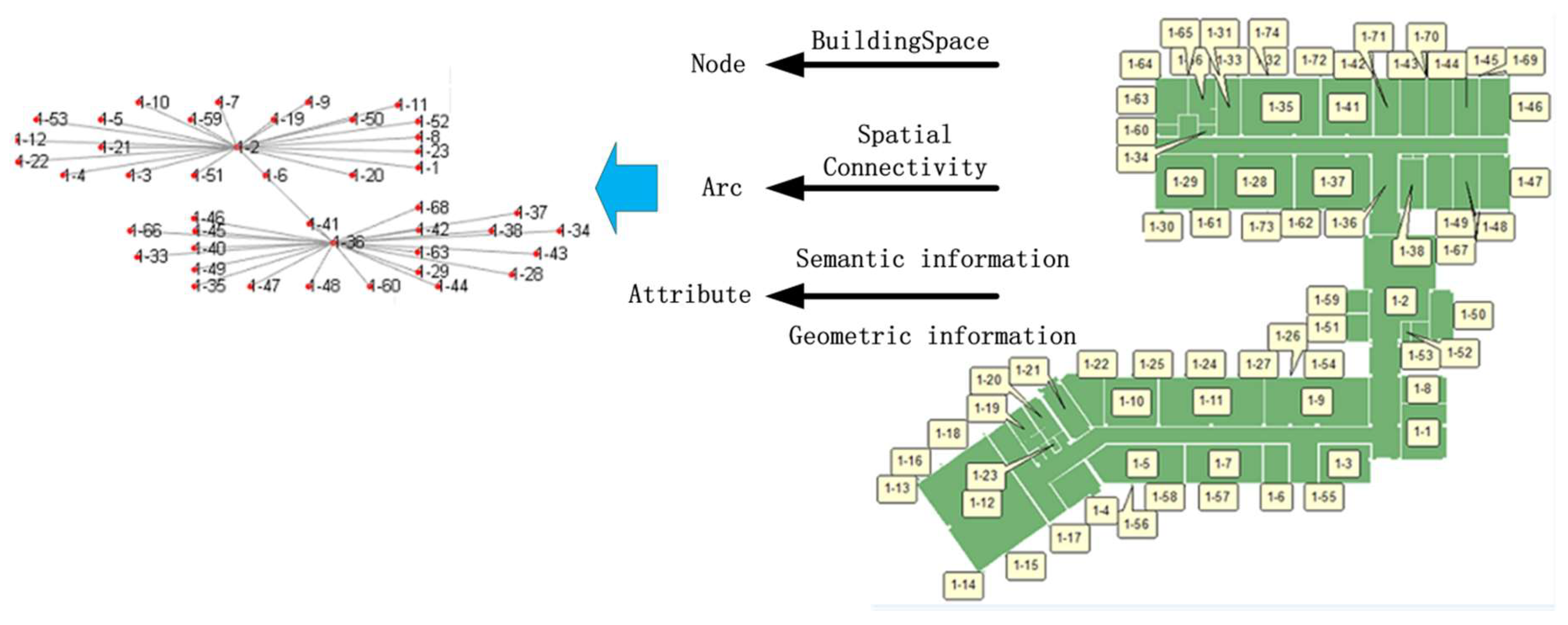
However, there are differences between IFC and the MNME. Firstly, in an MNME, nodes represent spaces in a building and the arcs represent connecting relationships between spaces. These two types of information cannot be directly extracted. Secondly, unlike the general network model, the MNME needs to take the relevant characteristics into consideration. This information must also be extracted from the semantic, geometric, and relational information contained in the IFC model. Therefore, to convert to an MNME, the following issues must be addressed: first, the corresponding information on nodes and arcs must be extracted from the entities and relational objects to realize the construction of nodes and arcs in the MNME; second, the attribute information related to evacuation should be automatically generated by the IFC.
Under the condition of solving the above issues, it is also necessary to integrate the calculated result of the MNME, which are mostly attribute information related to the building objects, with the building model itself. As a wonderful carrier of spatial data and attribute data, Geographic Information System (GIS) software has integrated them well when it was first introduced. After decades of development, many GIS vendors have updated their software for several times, making it more powerful in data expressing. Therefore, based on the powerful ability of GIS software in expressing spatial data and attribute data, the GIS software is used to integrate the calculated results of the MNME with the building data model. It is easy to express the spatial distribution and dynamic processes of various features in the building environment during the evacuation process.
To summarize, based on the entity model represented by the IFC, this study investigated methods of extracting nodes and arcs, as well as of constructing the characteristic attributes attached to them, through building entities and relationships. Based on this process, conversion to an MNME can be realized. The remainder of this paper is arranged as follows. Section 2: Analysis of the characteristics of the MNME. Section 3: Discussion of the basic ideas presented in this article. Section 4: Detailed description of the method used to construct an MNME based on IFC and express the simulation results in a GIS environment. Section 5: Using a large concert hall as a data source, an MNME is created based on the method proposed in this paper. The method is verified using EVACNET4 [32]. Section 6: The conclusions are presented.
2. Analysis of Macroscopic Network Evacuation Models
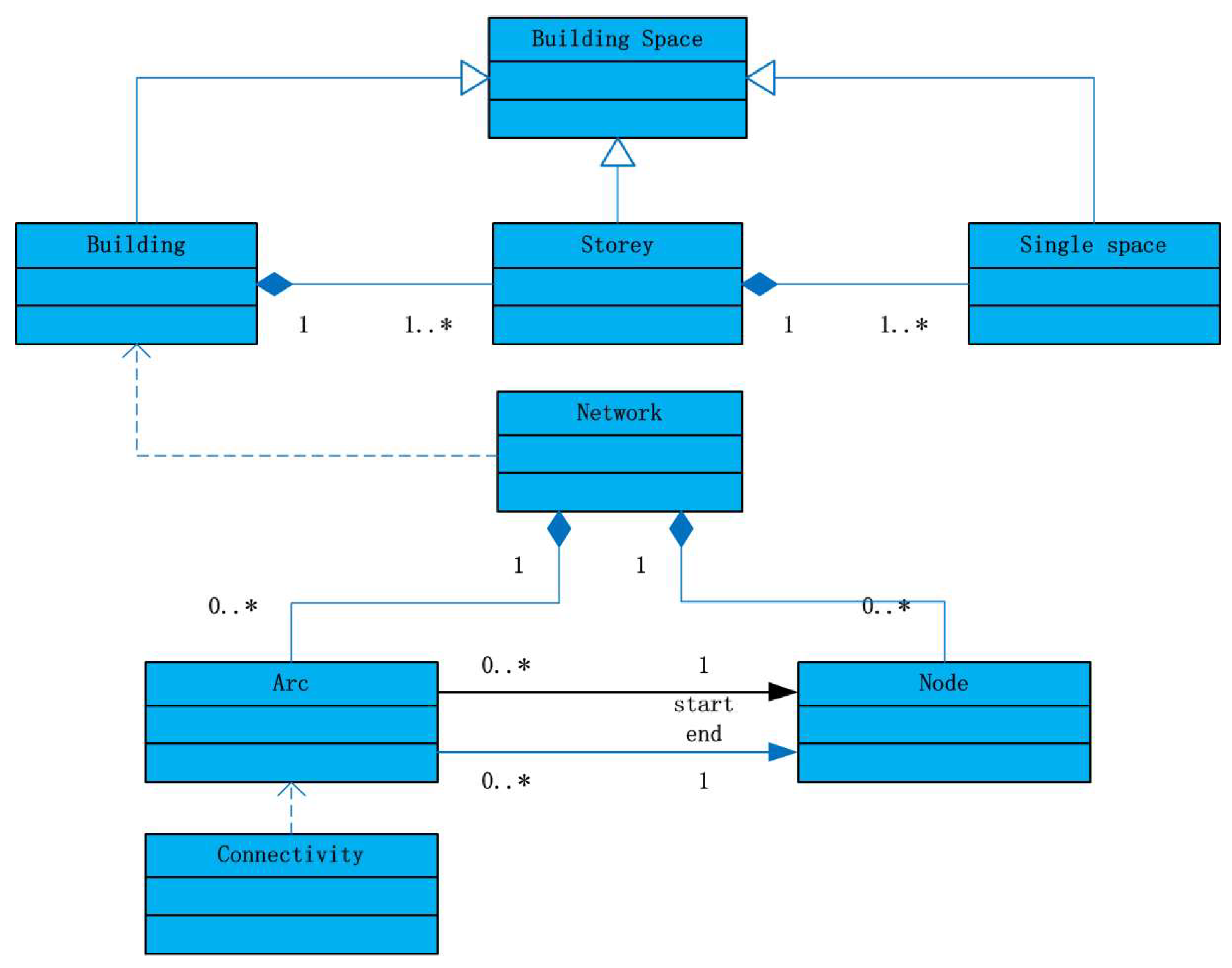
Presently, many macroscopic network models exist, such as EXIT89 [33], BGRAF [34], EVACNET4 [32], and Takehashi et al.’s model [35], etc. Analyses show that these models generally map buildings to nodes and arcs, as shown in Figure 1.
The spatial geometric model of an MNME includes two geometric objects: node and arc. Each node represents a room in a building (see Table 1), and its geometric information includes the area of the room and the coordinates of the center point. The arcs represent the connecting paths of each room in the building, and its geometric information is the length of the path.
Based on the nodes and arcs, the model also requires corresponding attribute information to assist simulation analysis. These attributes can be divided into three categories: node- and arc-related attributes, crowd-related attributes, and environment-related attributes (See Table 2).
In summary, the core of an MNME is a network created by nodes and arcs. Unlike other network models, an MNME also requires attributes related to nodes/arcs, the crowd, and the environment. Hence, to construct an MNME, the network structure and related attributes are both required.
3. Key Concepts of This Study
The core problem to be solved here is the transformation from a semantic information model represented by IFC to an MNME as well as the representation of the calculation results and building data model together. Unlike a general network model, an MNME contains a large amount of attribute information related to evacuation in addition to a network structure. Two difficulties must be solved: first, how to map the IFC semantic information model to the network model; and second, how to transform the relevant information contained in the IFC model into the attribute information for the MNME. Additionally, the influence of different operating conditions (e.g., states of openings) should be considered during simulation, and the related methods should be able to support automatic adjustments of the network structure. Finally, a solution must be considered to represent the calculation result of the MNME together with the building data model in a unified environment.
Considering this issue, this study uses the semantic, geometric, and relational information contained in the IFC to construct the nodes and arcs required in the MNME, so as to realize the mapping from the semantic information model to the network model (including related attributes).
The processes involved in achieving this transformation are as follows (see Figure 2):
(1) Generation of MNME Nodes
Nodes provide the network structure, representing the space in the semantic information model. Here, the spatial hierarchical relationships of IFC are used to extract the relevant space and to map them to nodes.
(2) Generation of MNME Arcs
Arcs provide node connectivity. Therefore, the key issue is generating connectivity between nodes, which includes horizontal connectivity on the same floor and vertical connectivity between different floors. The arcs can be generated based on openings and stairs in the IFC, which can connect different spaces.
(3) Construction of Attributes Attached to an MNME
An MNME contains an enormous amount of attribute information related to evacuation, which can be divided into the following types: node-and arc-related attributes, crowd-related attributes, and environment-related attributes. This paper discusses the three types of attribute and realizes the automatic generation of attributes from semantic, geometric and relational information in the IFC.
(4) Local Adjustment Mechanism for the Network under Different Operating Conditions
During the simulation, different operating conditions may have different consequences. In particular, some operating conditions may cause changes in the network structure (such as the presence of fire doors and windows on the ground floor, whose “opening state” will determine whether or not they can be used as passages in an emergency situation). Considering this issue, this paper discusses the automatic response of the network model structure to changes in operating conditions in order to adapt to adjustments in the network.
(5) Integration of Calculation Results and Building Data Model in a GIS Environment
Considering that the calculation results are often the attribute information related to building spaces and building elements, it is better to relate the evacuation results to the building model and they can be displayed in corresponding GIS software. This paper uses ArcScene as the environment to transform the building data model into a format that can be expressed in the software. On this basis, the information calculated by the software is attached to the corresponding features as the attributes, and finally their integrated expression is realized.
4. Construction of an MNME Based on the IFC Model
4.1. Generation of Network Structure Based on IFC Data
4.1.1. Construction of Nodes
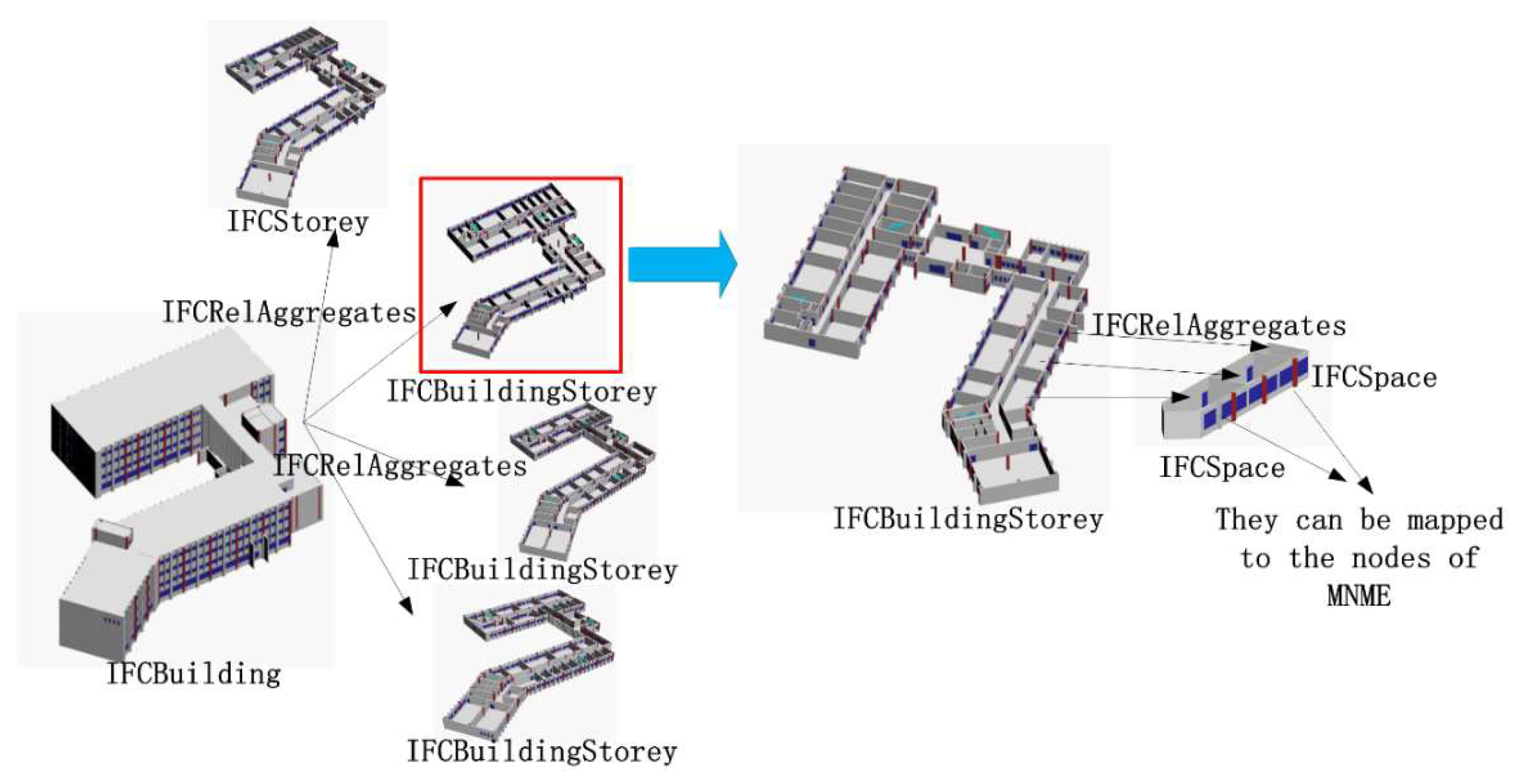
To generate the node information in a macroscopic evacuation network, all the spaces must be extracted. The IFC model classifies building objects into two parts: the building element and the space. There is a hierarchical relationship between different types of spaces in the IFC. For a building, the first level is the building itself, the second level is the building’s stories, and the third level is the single space that is organized based on the “IFCRelAggregates” relationship. The nodes of the MNME are formed by mapping the single spaces (IFCSpace). Combined with the characteristics of the IFC, the following methods are used to form the node (see Figure 3):
- (1)
- Extract the top-level space, termed “IFCBuilding.”
- (2)
- According to the “IFCRelAggregates” entity, search for stories (“IFCBuildingStorey”) that are associated with the building obtained in step 1, so that the second-level spaces (stories) can be obtained.
- (3)
- For each story obtained in step 2, use the “IFCRelAggregates” relationship to search for the subspaces (“IFCSpace”) related to this story, thus obtaining all the required single spaces. These spaces are the nodes that are needed for network extraction.
4.1.2. Generation of Arcs
Generating spatial connectivity is critical to creating an arc. Spatial connectivity is implicit in IFC, and arcs can be derived from the existing IFC relationships and building elements. Connections between different spaces usually use openings (doors or windows) as a medium. Therefore, the first step is to obtain the openings, and then find all the spaces associated with them. Subsequently, we can derive the spatial connectivity. Therefore, the analysis of this step involves not only the spatial relationship but also an analysis of building elements. In summary, the steps for generating arcs in an MNME are as follows.
(1) Derivation of Connectivity between Rooms (“IFCSpace”)
Spatial connectivity refers to two adjacent rooms that share the same “openings” such that a passage can be established. Therefore, rooms being “adjacent” is a necessary factor for judging spatial connectivity. For two adjacent spaces, the spaces must share the same building elements. That is to say, the same building elements must be present at their boundaries. Therefore, based on the spatial boundary relationship “IFCRelSpaceBoundary” of the IFC, shared building elements can be used to judge spatial adjacency and spatial connectivity. The method used to find the connected spaces associated with a single room is as follows.
- (a)
- For a specific space named Rx, search for the elements (“IFCBuildingElement”) through “IFCRelSpaceBoundary” entities, such as walls (“IFCWall”), slabs (“IFCSlab”), etc.
- (b)
- For the elements obtained in step 1, all associated spaces can be found using the “IFCRelSpaceBoundary” entity. If there exists any associated space that is not Rx, then the space and Rx are adjacent spaces, and the element is the shared boundary of the two spaces.
- (c)
- For all shared boundary elements found in step 2, search for “IFCRelVoidsElement” entities, and judge whether these shared elements include openings (“IFCOpeningElement”). If they do include openings, the two spaces are connected, and the openings on the shared boundary are the passages for the two connected spaces.
- (d)
- Map the extracted connectivity to the arc and connect to the relevant spaces.
(2) Extraction of Spatial Connectivity on Different Floors
In addition to the connectivity between rooms, the MNME arcs also include the connectivity between different floors. This requires the additional generation of spatial connectivity between floors. For different floors that are connected by stairs, the creation of spatial connectivity can be realized. The method is as follows (see Figure 4):
- (a)
- Extract the Top-Level Space—Termed “IFCBuilding.”
- (b)
- According to the “IFCRelAggregates” entity, search for stories (“IFCBuildingStorey”) that are associated with the building obtained in step 1, so the second-level spaces are obtained.
- (c)
- For each story obtained in step 2, we use the “IFCRelContainedInSpatialStructure” entity to search for elements (“IFCBuildingElement”) of the “IFCStair” type in the relevant story to obtain all the stairs.
- (d)
- For each stairs obtained in step 3, further search for “IFCRelContainedInSpatialStructure” in the model to obtain all the associated stories; these stories then have vertical connectivity.
- (e)
- Map the extracted connectivity to the arc connected to the relevant stories.
(3) Local Adjustment Mechanism for the Network
In evacuation simulations, it is often necessary to consider the impact of different conditions on the simulation results. It is particularly important to rapidly generate a corresponding network model for different operating conditions. Based on an analysis, it can be concluded that although there is no change in the overall structure of the building, the change in operating conditions actually corresponds to a partial change in the structure of the generated network. Therefore, in this paper, a local change mechanism for the network is proposed.
For the network, the main factor leading to a change is an alternation in the state of openings (i.e., doors and windows). For example, if an opening is the only medium of an arc, a closed state can result in removal of the arc. When an opening is not the only medium of an arc, a change of state will affect the possibility of passage (or “passing ability”), but does not result in removal of the arc. Furthermore, connections to the outside, such as windows on the ground floor, can serve as passages to the outside. Corresponding changes in the network not only reflect the addition/removal of some arcs, but also the addition/removal of some destination nodes.
Here, we use the following methods to respond to network changes caused by changes in the state of openings.
- (a)
- For a specific opening, search for the corresponding arc in the network.
- (b)
- If the state of the opening has changed from open to closed, take the following conditions into consideration.
- (i)
- If the related arc has only one opening, delete the arc and further consider the following condition: if the arc is on the ground floor, remove the destination node attached to it.
- (ii)
- If the arc is related to at least two openings, reduce the passing ability of the arc (the calculation method for passing ability is discussed below).
- (c)
- If state of the opening has changed from closed to open, take the following conditions into consideration.
- (i)
- If the opening was not previously related to any arc, create an arc and further consider the following condition: if the opening is on the ground floor, add a connecting destination node and calculate the passing ability of the arc, but if the opening is not on the ground floor, find related spaces to generate an arc and calculate the passing ability.
- (ii)
- If the opening has corresponding arcs, find these arcs and recalculate the passing ability.
According to the method proposed above, the network structure can be created from the IFC (see Figure 5).
4.2. Automatic Classification of Nodes for Evacuation
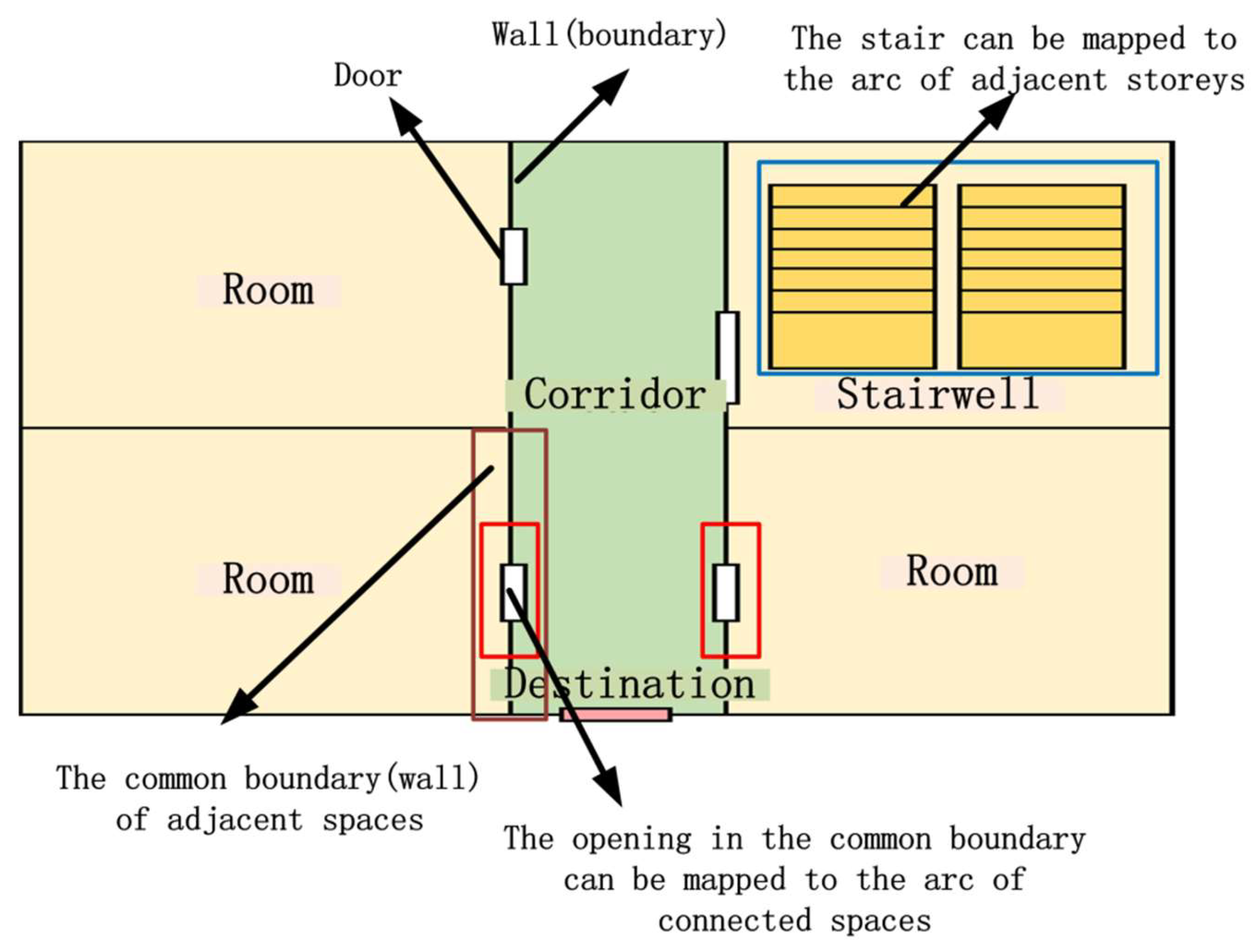
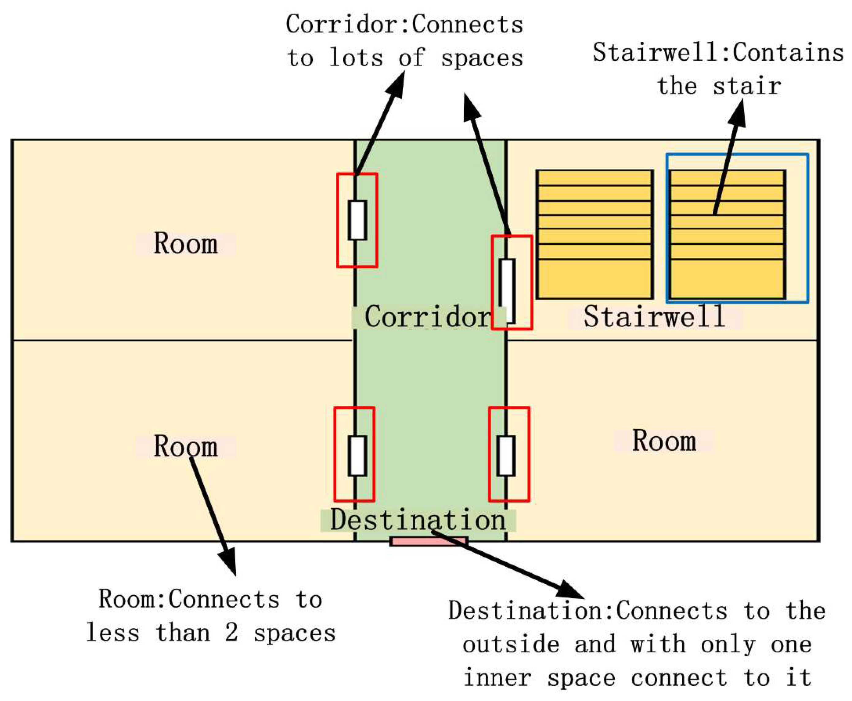
In the MNME, a single space can be divided into several categories, such as stairways, corridors, rooms, and destinations, as shown in Figure 6. Different types of building spaces also play different roles in the evacuation simulation. For example, corridors and stairways mainly function as passages, and hallways mainly function as entrances and exits. These are different from ordinary rooms. Therefore, such information is very important during an emergency evacuation and requires IFC relational information for correct classification.
- (1)
- Stairwells: this work uses the “IFCRelContainedInSpatialStructure” relationship to distinguish stairwells. Using the aforementioned relationship, we can obtain the relevant space and the stairs it contains. If a room contains an “IFCStair” element, this space node is designated as a stairwell.
- (2)
- Corridors: in this work, all single spaces are first traversed to find any connected spaces. When a space has more than two connected spaces, this space node is designated as a corridor.
- (3)
- Ordinary rooms: In combination with the results obtained above, when a room has one or two connected relationships, the space node is designated as a room. If the number of connected spaces is zero, this space could be a pipeline space. The passage cannot be used while evacuating; hence, it is not recorded as a node.
- (4)
- Destinations: It is generally believed that the escape of a disaster-prone building represents a successful evacuation. Therefore, when a space is on the ground floor, if there is only one inner space associated with a door, then this space is a destination. Additionally, in emergency situations, windows on the first floor can also be used as exits for escaping. According to the actual situation, windows on the first floor can also be set as destinations.
4.3. Calculation of the Attributes Attached to a Network
As mentioned above, generating an MNME requires not only a basic network structure, but also requires related attributes. These attributes can be classified into several types: node- and arc-related attributes, crowd-related attributes, and environment-related attributes. All attributes must be considered when generating an MNME.
4.3.1. Node- and Arc-Related Attributes
Most attributes related to nodes and arcs are geometric information on the building elements and building spaces. For example, the area of nodes, the height and width of openings, the distance between nodes, etc. All kinds of building objects in the IFC model have corresponding 3D geometric information. Therefore, most of these attributes can be extracted directly from geometric information. The method is described in Table 3).
4.3.2. Crowd-Related Attributes
Crowd-related attributes can be divided into two types. The first type is associated with occupants’ age, sex, and physical condition, and can be set according to the operating conditions. The second type is associated with the geometric information of nodes and arcs, and can be extracted from the IFC and calculated using an empirical formula (see Table 4).
(1) Space Capacity and Initial Number of Occupants of a Node
For a node, attributes such as the space capacity and the initial number of occupants must be calculated. Space capacity refers to the maximum number of occupants that a room can hold. This capacity can be very large if it is not limited as for destination nodes. For other nodes, the capacity is nmax, and is given by Equation (1) [32]:
Ar is area of the node (m2);
P is the per capita area (m2/person).
The space capacity is an important factor, and it can be calculated using the area of the space. Therefore, the maximum number of people that an ordinary space can accommodate can be derived from the average area of the spaces. This can be obtained from Equation (1), which factors in the area of the space and the per capita area.
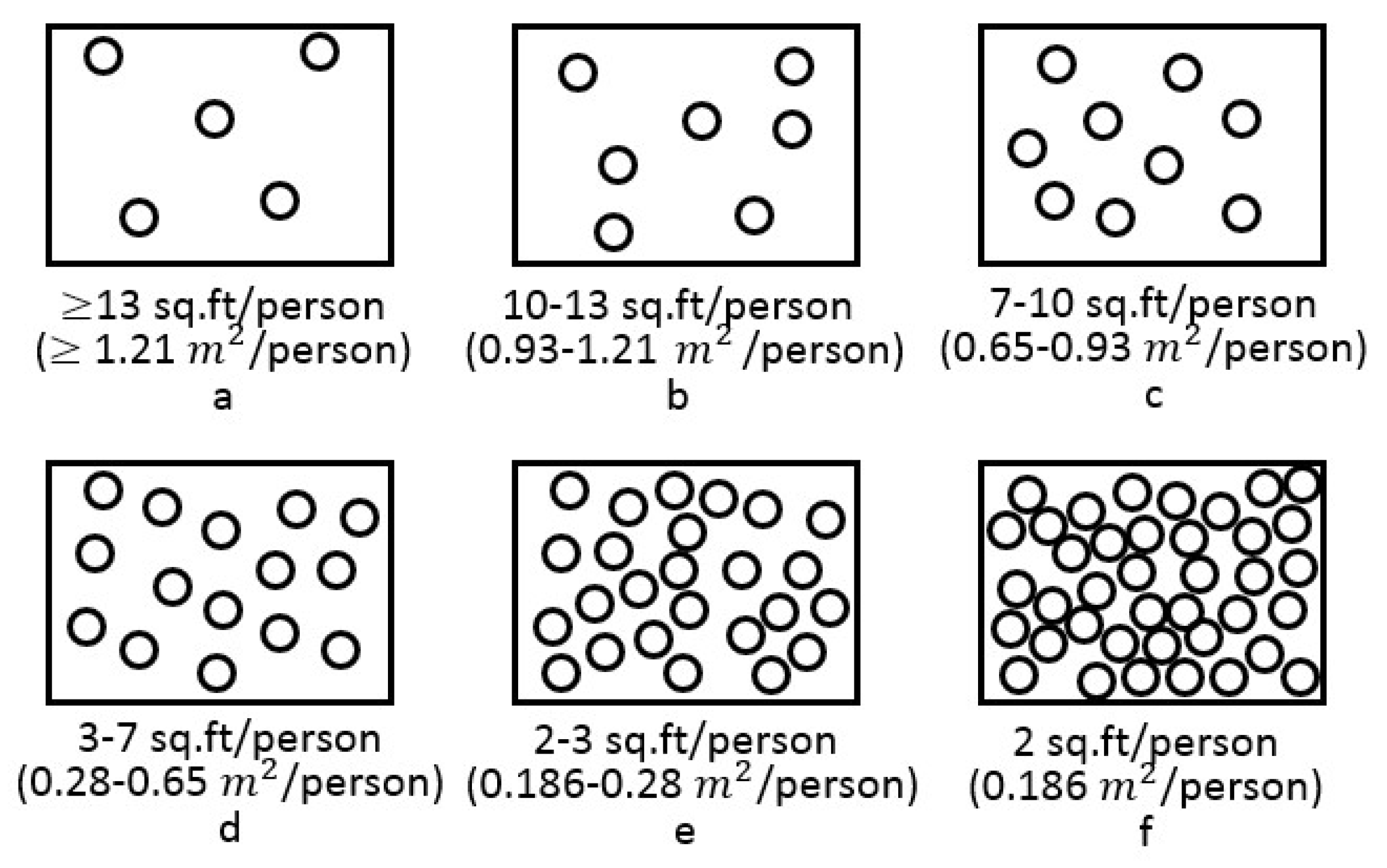
The area of a space can be directly calculated from the geometric information on the space, which can be directly extracted from the IFC. The per capita area of a node can be inferred using the method shown in Figure 7. The calculation of these factors depends on the type of building and usage conditions. For example, under normal circumstances, a teaching building can use “b” or “c” conditions, and a train station during the holidays can use “d” or “e” conditions (see Figure 7). In an emergency, highly dense corridors can use the “f” condition (see Figure 7).
In summary, the following steps can be taken to calculate the space capacity and the initial number of occupants.
- (a)
- For a specific space, the attached geometric information is obtained from the IFC and its area is calculated.
- (b)
- The per capita area is obtained under different conditions (see Figure 7).
- (c)
- Based on steps 1 and 2, the space capacity is calculated according to Equation (1).
- (d)
- The initial number of occupants of a node can be randomly generated between 0 and the required space capacity based on the simulation needs.
(2) Flow Direction of Crowds in a Network
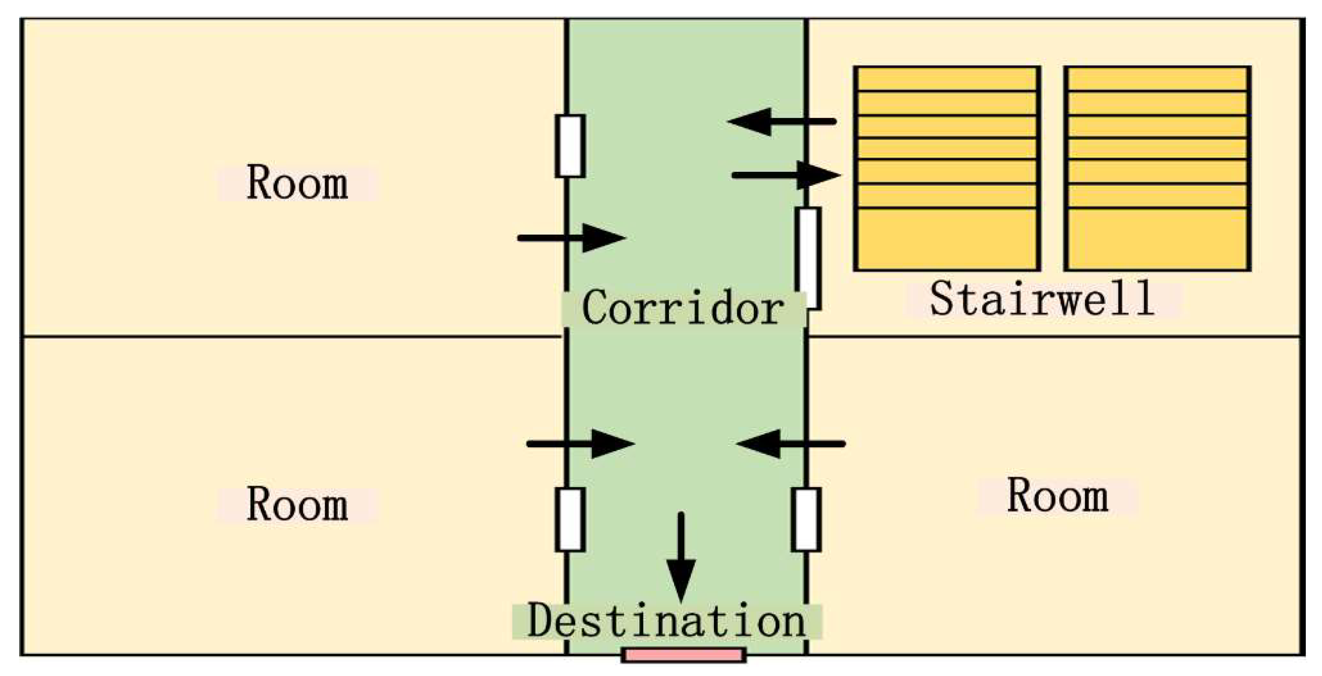
The flow of people along arcs directly affects the results of an evacuation. Therefore, it is necessary to decide the flow direction of people according to different types of spaces in the IFC. Based on the connecting nodes, arcs can be divided into the following seven types: (1) room–room; (2) room–hall; (3) corridor–hall; (4) corridor–stairwell; (5) room–destination; (6) corridor–destination; and (7) stairwell–destination. These types directly determine the flow direction along an arc (see Figure 8).
In an emergency, the directions that evacuees traverse are basically the same. Evacuees run from the rooms to the corridors and then to the stairwells on the same floor before finally arriving at destinations. The fifth, sixth, and seventh arcs are single-direction arcs pointing to the destination.
Before the evacuees find a stairwell, the direction of flow is uncertain. For example, if the person is unfamiliar with the evacuation route, it is possible that the person may choose to traverse in any direction along the corridor. In this case, the arc needs to be set as a bidirectional arc, such as the first and third types. The fourth type of arc connects corridor nodes to stairwells. Because the stairwell is a shared space between two floors, the crowd may move from the corridor to the stairwell, or it may move in the opposite direction. Therefore, it must be set as a bidirectional arc. The second type of arc should be set as a one-way arc under normal circumstances; however, it can also be set as a bidirectional arc depending on the layout of the building and the specific conditions of the evacuation facility.
(3) Calculation of Walking Speed and Passing Cost for an Arc
In an MNME, the passing cost of an arc is a function of the passing time and passing ability.
Passing time refers to the time taken to traverse a given path; passing ability refers to the number of people that can traverse the path per unit time. Passing time can be determined using Equation (2) [32]:
T is the time taken to traverse a path (seconds);
LDIST is the distance between two nodes (meters);
V is the walking speed of an individual (meters per second).
Passing ability can be determined using Equation (3) [32]:
N is the number of people who traverse the route per unit time (people per second);
We is the valid width of the passage (meters);
q is the number of people in a unit width of a passage for a given time (people per meter per second).
The time spent in a passage can be calculated using Equation (2), where the length of the path can be calculated directly from the distance between the midpoints of the two nodes. Therefore, another important factor is the walking speed.
As shown in Figure 9, the walking speed of individuals in various kinds of crowded scenarios are different. An appropriate walking speed can be selected according to the type of building and the usage conditions. For example, outside holiday periods, conditions “b” or “c” (see Figure 9) might be appropriate; for the connecting passage between a cinema theater and its exit, “d” or “e” may apply (see Figure 9); and for a large conference hall or venue, condition “f” may apply (see Figure 9).
Therefore, the passing time of arcs can be calculated as follows:
The passing ability, using the width information of the path and combining the appropriate operating conditions, can be estimated using Equation (3).
In addition, the number of doors and windows between two connecting rooms will serve as a reference for the passing ability. As shown in Figure 10, when the doors connecting two rooms are similar in size, the passing ability with two doors (Figure 10b) is twice that with only one door (Figure 10a).
Therefore, the passing ability of arcs can be calculated as follows:
- (a)
- obtain the number of people per unit width per unit time under a specific condition (see Figure 9);
- (b)
- calculate the opening width of the arcs using the method stated in Table 3;
- (c)
- use Equation (3) to calculate the passing ability based on step 1 and step 2; and
- (d)
- if there is more than one opening, calculate the passing ability of each opening according to steps 1–3 and finally sum the values.
4.3.3. Environment-Related Attributes
Environment-related attributes include factors such as smoke concentration, smoke thickness, hot upper layer, cool lower layer, first source position, height of the fire source, flame, temperature, ambient temperature, etc. Most of these attributes are specific parameters entered into the model to simulate evacuation under different conditions. Relevant information cannot be found in the IFC, and so these attributes often need to be set according to the operating conditions before running the model.
4.4. Express the Calculation Results and Building Model in a GIS Environment
The results calculated by the MNME are often the attribute information related to building spaces and building elements. In order to make this information integrated with the building model, it is better to attach them to the corresponding building object and express them in the format of thematic map. This paper uses ArcScene as an environment for expression, the relevant method is as follows:
- (1)
- Generate Shapefiles for Each Story
- (a)
- Extract each single space (IFCSpace) in IFC based on the method described in Section 4.1.1. On this basis, the geometric information of the spaces are extracted from the IFC model, projected onto the plane, and then added to the shapefile of the layer.
- (b)
- Extract all the openings related to arcs in IFC based on the method described in Section 4.1.2. On this basis, the geometric information of the openings are extracted from the IFC model, projected onto the plane, and then added to the shapefile of the layer.
- (c)
- Use the elevation of the story as the Z value of all objects in the shapefile. Then, use the height of the story as the height value of all objects in the shapefile.
- (d)
- Loop through steps a–c to generate shapefiles for each story.
- (2)
- Attach Attributes to the Shapefiles and Visualize them in GIS Environment
- (a)
- For the attributes calculated by MNME, find the associated building elements or building spaces. And these attributes can be attached to the corresponding object in the shapefile as attributes.
- (b)
- The results are expressed in the corresponding thematic map (see Figure 11).
5. Experiment and Analysis
In order to validate the method, in this paper, the instance case to build the MNME and input the model into EVACNET4 (which is a typical software supporting MNME) is selected.
5.1. Experimental Data
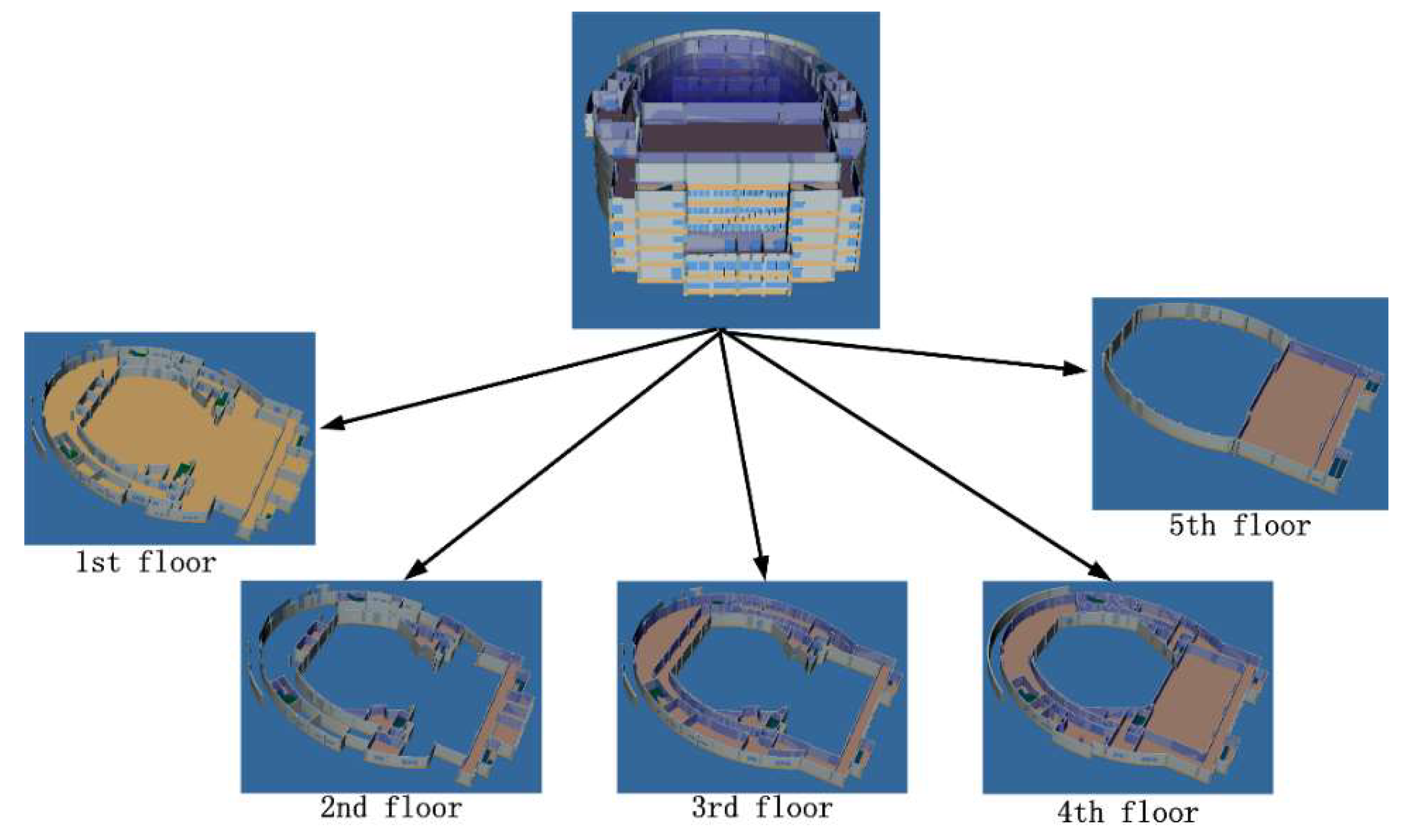
In this study, we used the IFC model of the Zhongbei Music Building, located to the northeast of the Xianlin Campus of Nanjing Normal University, to obtain the experimental data. The main structure of the North China Music Building is a five-story framework structure, which is the most common type of public building (see Figure 12). The simulation time is the performance period during ordinary working days. During this period, the concert hall is crowded. In addition, it is also necessary to consider whether the “window” elements in the building can be opened or not, whether the “window” elements can be used as passageways to a room or a corridor, or whether they allow passage to a destination.
5.2. Experimental Environment
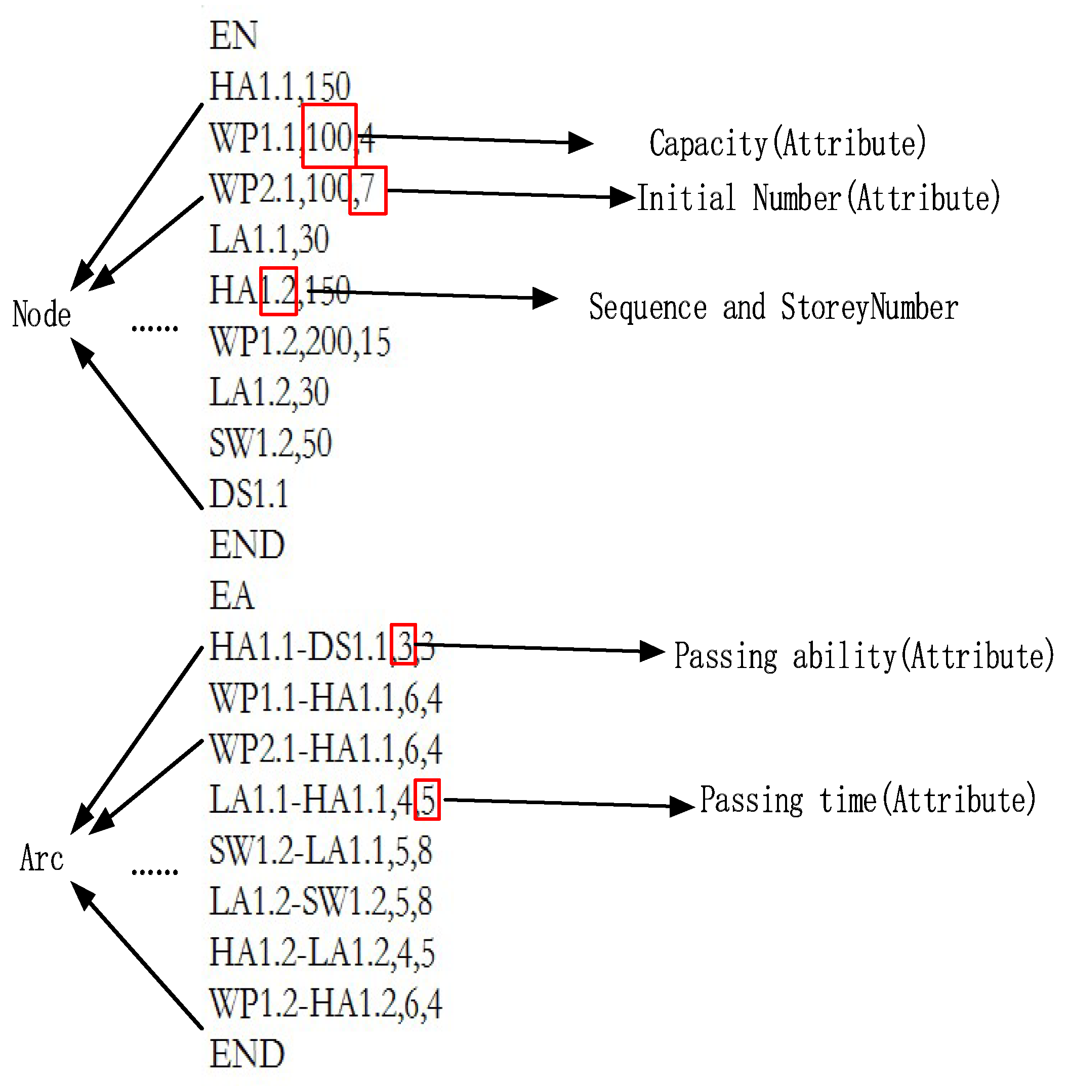
EVACNET4 uses a text file that consists of two parts as its input. The first part describes the association of information, including type, serial number, story, space capacity, and initial number of people, with each node. The second part describes the arcs’ information in the network, including passing ability and passing time, and the two ends of each arc (see Figure 13).
EVACNET4 uses a special node specification scheme to define each node in the network model (listed in Table 5). The definition of this node is also its address. Consider a standard node named “WP2.3” as an example. “WP” represents the node type of a room, “2” is the sequence number of the room, “.” is a delimiter, and “3” is the story number. The number after each node name is the attribute value attached the node, including space capacity, initial number of spaces, etc. Therefore, the meaning of “WP2.3,100,10” is that the node of room 2 on the 3rd floor can accommodate up to 100 people and contains 10 people initially.
The definition of arcs is very simple in EVACNET4. For example, the arc between node WP1.3 and node HA1.3 can be expressed as WP1.3-HA1.3. The numbers after each arc name refer to attributes, such as the passing ability, passing time, etc. Therefore, the meaning of “WP1.3-HA1.3,5,1” is the passage from room 2 to hall 1 on the 3rd floor, which can allow five people to pass per second, with each person requiring one second to traverse this passage.
From the analysis above, we can see that the information required in EVACNET4 includes nodes, arcs, and related attribute information. All the information mentioned above can be extracted from the MNME. Therefore, the input of EVACNET4 can be generated easily using the MNME.
5.3. Experiment Design
5.3.1. Basic Operating Conditions
Operating Condition 1: A total of 1683 people were placed in the building. The people were randomly distributed throughout the building (800 people in the first-floor hall, 300 people in the third-floor hall, and the remaining people randomly distributed in other rooms) using a computer. The “window” elements in the building were closed.
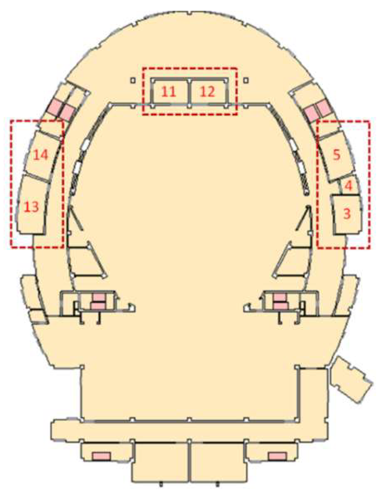
Operating Condition 2: A total of 1683 people were generated in the building and randomly placed throughout the building (800 people in the first-floor hall, 300 people in the third-floor hall, and the remaining people randomly distributed in other rooms). Two “window” elements that connect the interior spaces on the ground floor of the building were open, and the “window” elements in five rooms on the ground floor were also open.
The difference between the two operating conditions is that the “window” element that connects the inside and the destination on the ground floor of the building was open for operating condition 2 (the windows of rooms No. 3, No. 4, No. 5, No. 11, No. 12, No. 13, and No. 14 can be opened, as shown in Figure 14).
5.3.2. Experimental Procedure
The experiment followed four steps. Step 1 was to create the network structure and the relevant attributes of the MNME according to the IFC model of the Zhongbei Music Building. Step 2 involved mapping the MNME to the input file required in EVACNET4, and running the simulation based on the file. Step 3 involved obtaining the results and expressing them together with the 3D building model in a unified environment. Step 4 involved simulating the model under operating condition 2, and comparing the results with those for operating condition 1.
5.4. Results and Discussion
5.4.1. Experiment Results
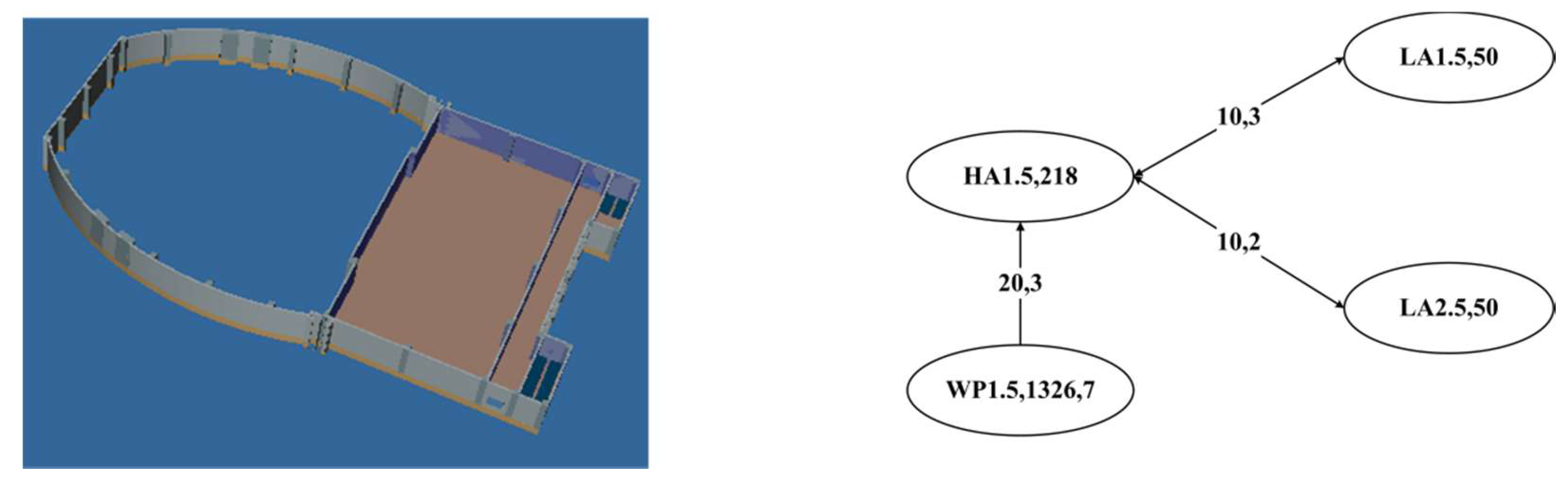
1. Network Structure Generation
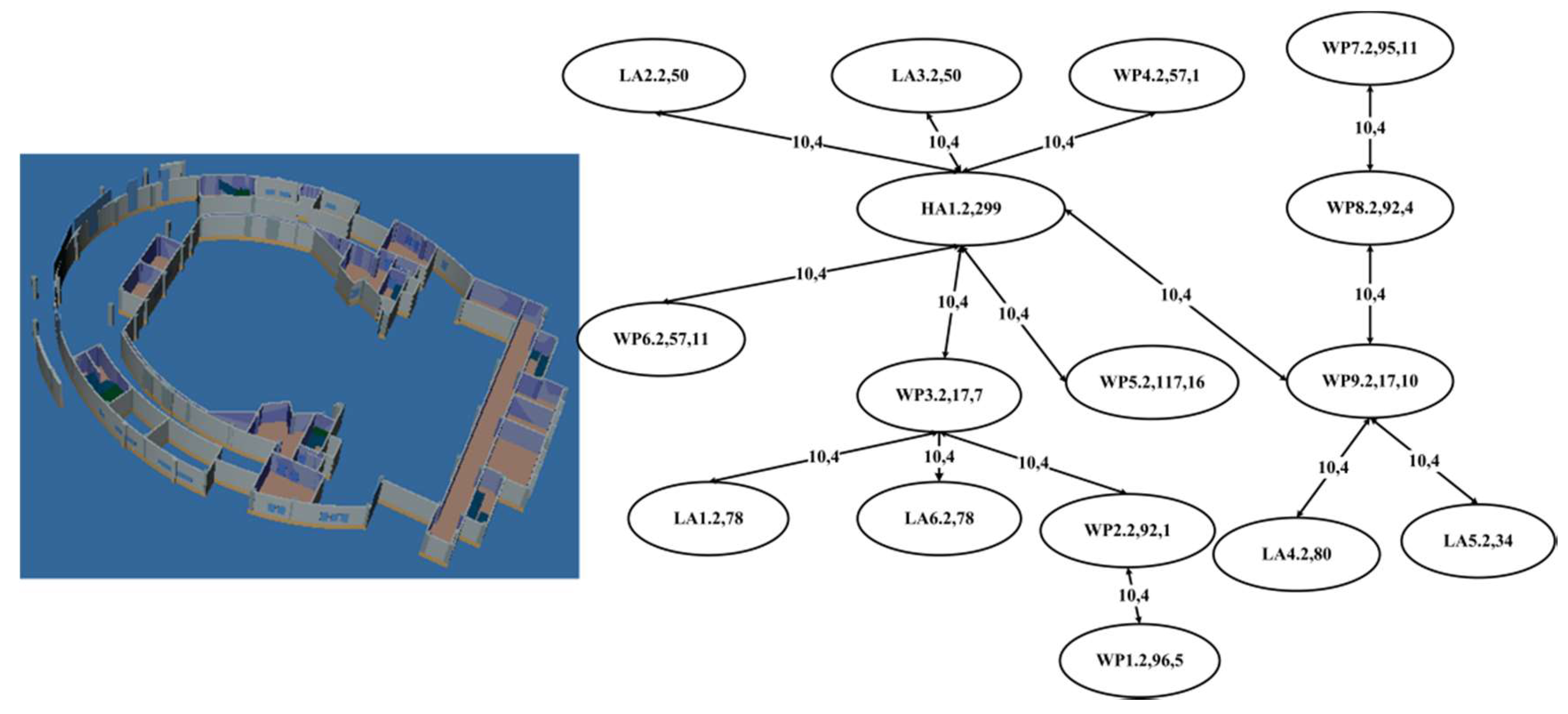
Using the method proposed in Section 4, the rooms in the IFC were mapped to nodes and the generated spatial connectivity was mapped to an arc (see Figure 15, Figure 16, Figure 17, Figure 18 and Figure 19). According to the semantic, geometric and relational information, the types, space capacity, initial number of people, and other information attached to the nodes were derived from the IFC. The flow direction, passing ability, passing time, and other attributes of the arcs were also calculated. Using the aforementioned values and parameters, the MNME model was created.
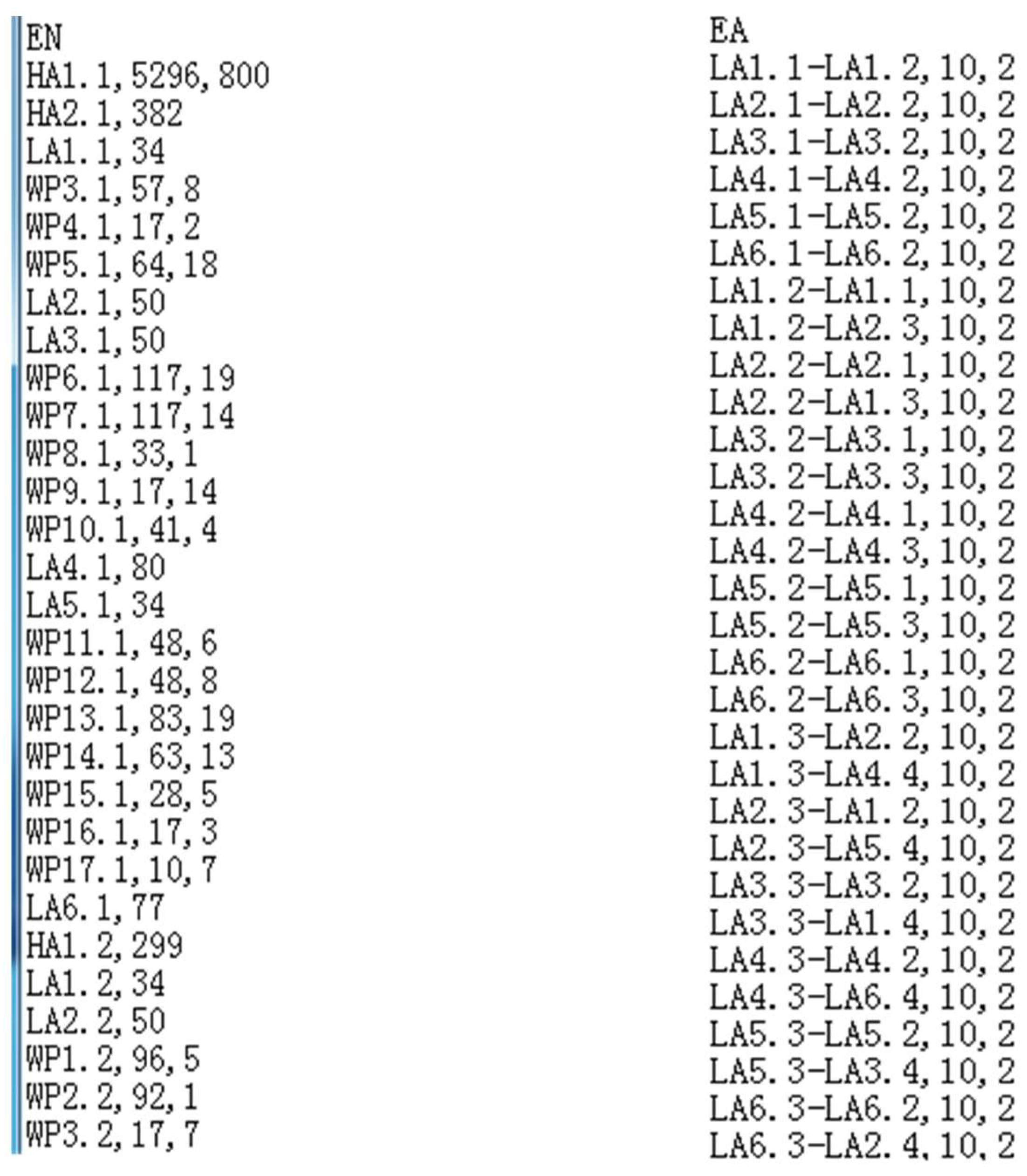
2. Input File Generation and Software Operation
First, the nodes, arcs, space capacity, initial number of occupants, passing ability, and passing time attributes were extracted by the MNME created by step 1. This information was then written into the EVANET4 input file (see Figure 20). Then, the evacuation simulation was run using this file and results were generated.
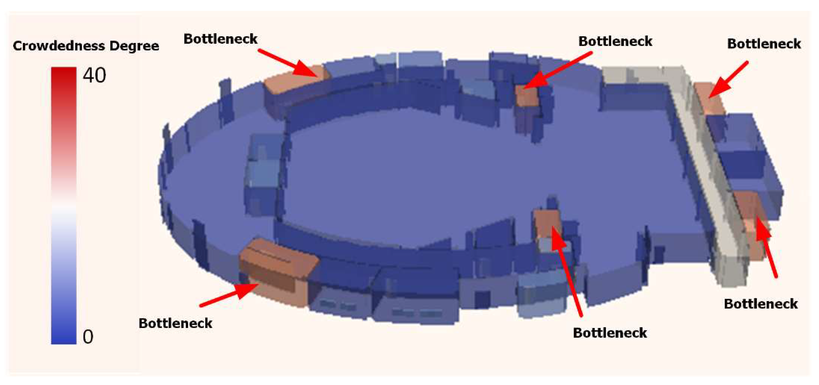
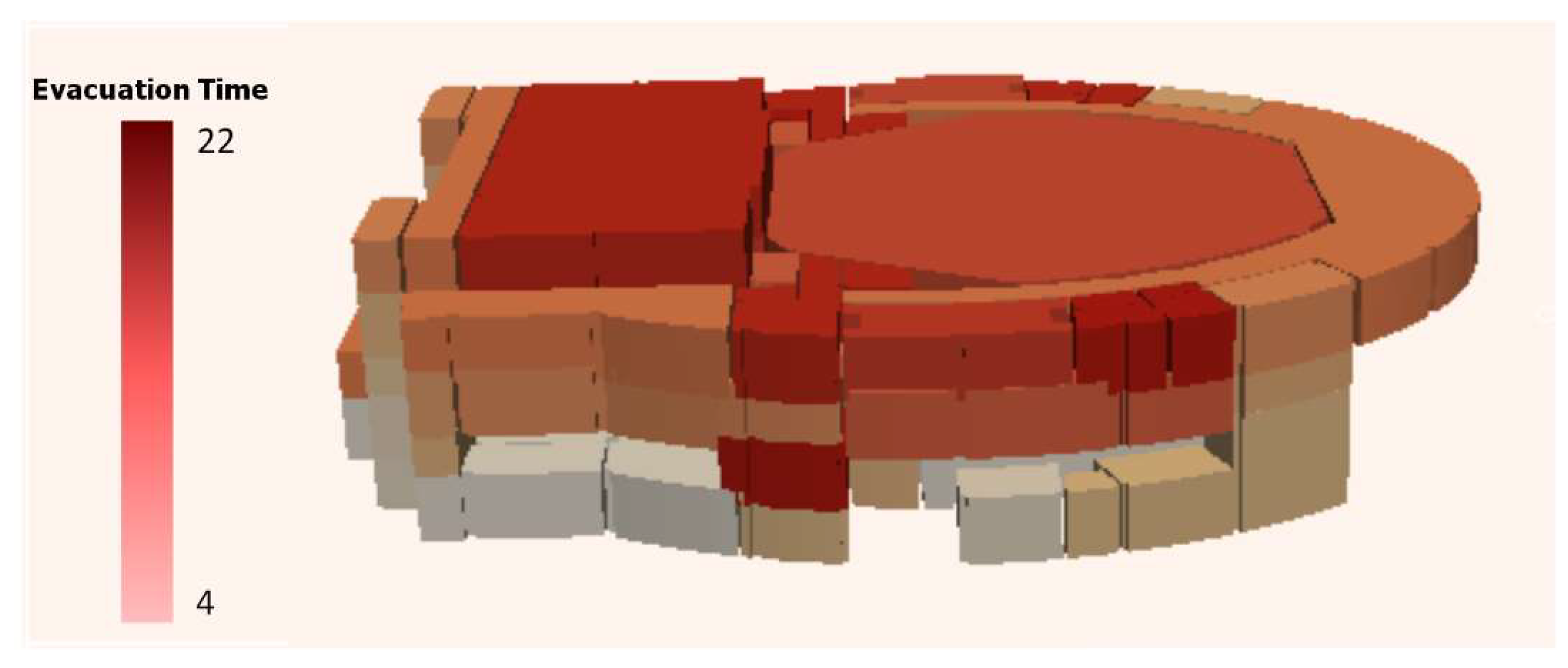
3. Expression of Running Results
The EVACNET4 simulation results were restructured and the result items, including evacuation time, crowdedness degree, and evacuation bottlenecks, were attached to the 3D building model. Hence, they can be expressed in a unified 3D scene (see Figure 21 and Figure 22).
4. Comparison of Operating Conditions
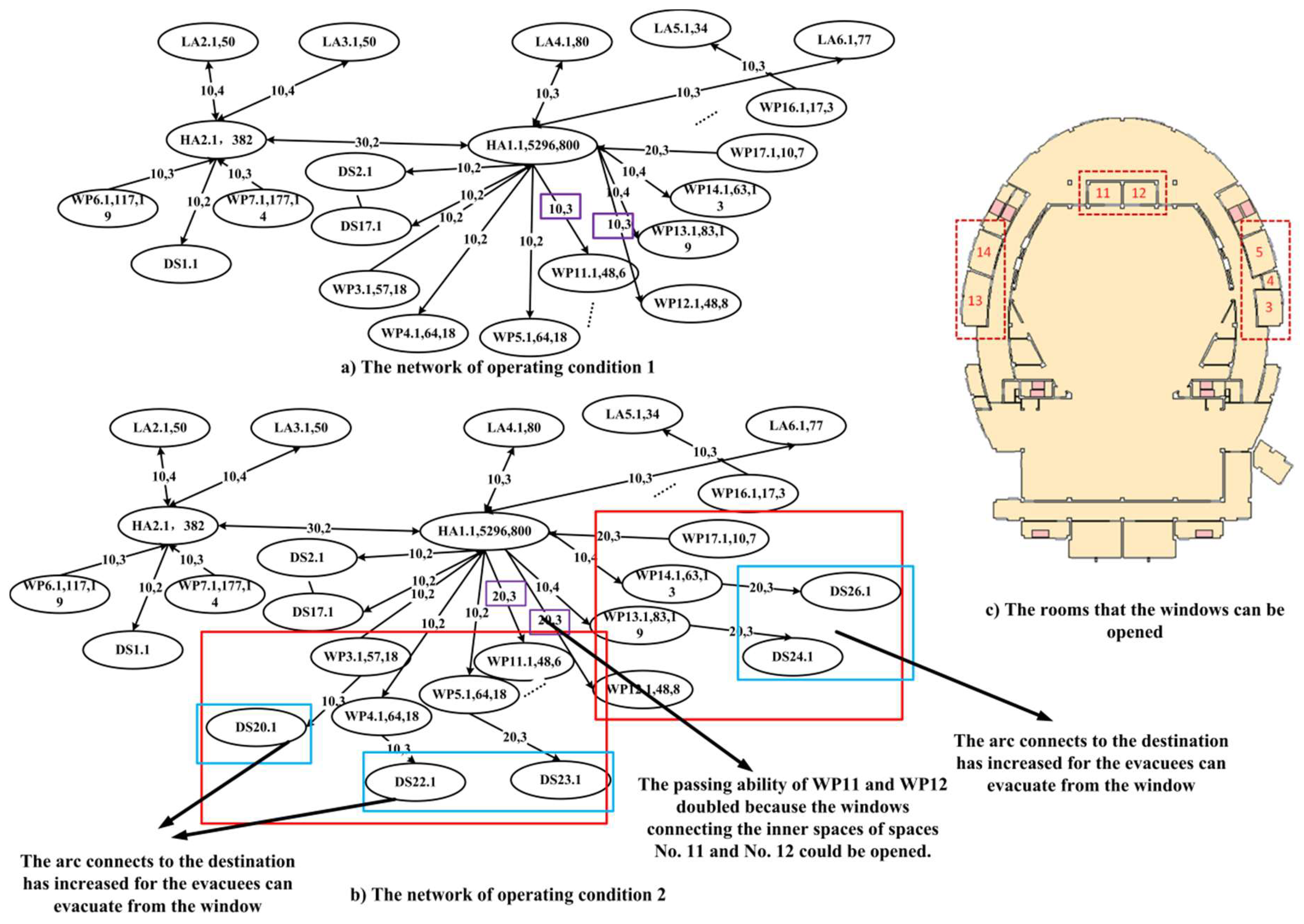
In this experiment, the changes in working conditions for spaces No. 3, No. 4, No. 5, No. 11, No. 12, No. 13, and No. 14 are mainly reflected in whether or not windows can be opened. It can be concluded that the above changes in the operating conditions caused two major changes in the experiment. First, the windows in No. 3, No. 4, No. 5, No. 13, and No. 14 connected to the outside and could be opened, meaning that the number of arcs connected to the destination increased. Second, the windows in spaces No. 11 and No. 12 (connecting the hall) could be opened, changing the passages from the room to the opening from one to two. This doubled the passing ability of the arc (See Figure 23). Based on the above-mentioned modification information, a partial modification was made to the original image, and the network structure for condition 2 was generated.
Figure 23 shows a comparison of the number of people passing through the nodes for each of the two operating conditions. It can be seen from the figure that windows No. 3, No. 4, and No. 5 could be opened for operating condition 2, and people could directly evacuate through these windows. The corresponding “window” elements serve as the arcs connecting to the destination. Subsequently, the “window” components became the “path” for crowd evacuation.
5.4.2. Discussion
(1) Automatic Generation of the Model
From step 1 to step 3 of Section 5.4.1, it can be seen that, using the method described in this paper, we can realize mapping from the IFC to the network structure of an MNME. Based on this method, construction of the related attributes required for the MNME can be realized. An MNME contains the node, arc, and related attribute information required by EVACNET4. Therefore, the transformation to EVACNET4 can be realized based on the constructed information in the MNME. The final simulation can then be realized. Additionally, the whole process, including the generation of nodes and arcs, and the construction of related properties such as passing ability and passing time, is an automatic process that does not require manual interaction.
Traditional simulations based on EVACNET4 usually create the nodes, arcs, and related attributes manually. Owing to complex construction conditions, this traditional method is both labor-intensive and may cause mistake. These limitations may lead to poor simulation results.
(2) Response to Changes in the Network Model
During the evacuation process, it is often necessary to consider the effects of different states of openings on the network structure (see Figure 24). The method proposed in this paper modified a network structure and compared results. Figure 24 shows a comparison for network structures under two different operating conditions which are both generated automatically. It can be seen from the figure that, under different operating conditions, the generated network structure changed. The passing ability of WP11 and WP12 doubled because the windows connecting the inner spaces of spaces No. 11 and No. 12 could be opened. Because the windows of spaces No. 3, No. 4, No. 5, No. 13, and No. 14 could be opened, the rooms WP3, WP4, WP5, WP13, and WP14 had arcs that directly connected to the destination.
Therefore, the method described in this paper can respond to changes in the network structure. The modified network, which is input into EVACNET4, can affect simulation results.
(3) Applicability of the Method
This method contributes to automatic construction of network structures from the IFC, and automatic generation of most of the attributes that are independent of the MNME conditions. In essence, this work solves the problem of transforming from a semantic information model to an MNME. Its core idea is to construct the nodes, arcs, and related attribute information for the MNME through the semantic, geometric, and relational information of a semantic information model. Therefore, this method could be applicable to many popular semantic information models (such as CityGML) for automatically creating an MNME.
Naturally, this method also has some limitations. An MNME may have specific environment-related attributes that were not considered in this work because the IFC does not provide the required information; therefore, they can only be set manually. Nevertheless, our method promotes efficient evacuation simulations and bridge the gap between BIM and MNME.
6. Conclusions
In this paper, we addressed the low-efficiency issue in the indoor crowd evacuation modeling process. Research on the construction of an MNME, based on IFC, was conducted, and the differences between the IFC model and the MNME were comprehensively analyzed. Based on the aforementioned research and analysis, the nodes, arcs and relevant attributes in an MNME can be extracted, and an automatic MNME implemented. The generated MNME is used as a data source for EVACNET4 and the results are visualized together with the building model in a GIS environment.
From the results presented in this paper, it can be concluded that the IFC model is compatible with various types of construction data. This model includes the semantics, geometry, and relationships that can be effectively mapped to the nodes and arcs required by an MNME. The method proposed in this paper effectively realizes the conversion from IFC to a MNME. Additionally, the generated network structure can be changed under different working conditions, and simulations for different working conditions can also be conducted.
In summary, the method proposed in this paper can realize the construction of simulations for the evacuation of an indoor crowd automatically based on IFC data. It can meet the needs of various operating conditions, and provides for the possibility of interaction between BIMs and emergency evacuations. Additionally, as an ideal carrier of spatial information and attribute information, GIS software can combine the calculation results with the building data model in an integrated environment.
In the future, we will consider an extension of this method, and study the transformation methods from CityGML, and other semantic information models, to the MNME. In addition to macroscopic models, microscopic and mesoscopic models are also used in evacuation planning. The transformation from semantic information models to these types of model also warrants further research.
Author Contributions
Z.Z. made formal analysis and wrote draft of the manuscript. L.Z. made investigation. C.Z. provide the methodology, B.L., M.C., and Y.C. principally conceived the idea and provided financial support.
Funding
This research was funded by National Natural Science Foundation of China (Nos. 41501422), National Natural Science Foundation of China (Nos. 41571381), and Nantong Key Laboratory Project (Nos. CP12016005).
Conflicts of Interest
The authors declare no conflict of interest.
References
- Wen, Y.; Zhang, H.; Guonian, L.V.; Hong, Z.; Hong, T. Estate spatial data based building space modeling for the evacuation route. J. Geo-Inf. Sci. 2011, 13, 788–796. [Google Scholar] [CrossRef]
- Dimyadi, J.; Amor, R.; Spearpoint, M. Using BIM to support simulation of compliant building evacuation. In Proceedings of the 11th ECPPM, Limassol, Cyprus, 7–9 September 2016; pp. 511–518. [Google Scholar]
- Muramatsu, M.; Nagatani, T. Jamming transition in two-dimensional pedestrian traffic. Phys. A Stat. Mech. Its Appl. 2000, 275, 281–291. [Google Scholar] [CrossRef]
- Tajima, Y.; Nagatani, T. Scaling behavior of crowd flow outside a hall. Physica A 2001, 292, 545–554. [Google Scholar] [CrossRef]
- Frisch, U.; Hasslacher, B.; Pomeau, Y. Lattice-gas automata for the Navier-Stokes equation. Phys. Rev. Lett. 1986, 56, 1505–1508. [Google Scholar] [CrossRef] [PubMed]
- Okazaki, S.; Matsushita, S. A Study of Simulation Model for Pedestrian Movement with Evacuation and Queuing. Proc. Int. Conf. Eng. Crowd Saf. 1993, 271–280, 271–280. [Google Scholar] [CrossRef]
- Muramatsu, M.; Irie, T.; Nagatani, T. Jamming transition in pedestrian counter flow. Physica A 1999, 267, 487–498. [Google Scholar] [CrossRef]
- Helbing, D. Collective phenomena and states in traffic and self-driven many-particle systems. Comput. Mater. Sci. 2004, 30, 180–187. [Google Scholar] [CrossRef]
- Helbing, D.; Farkas, I.; Vicsek, T. Simulating dynamical features of escape panic. Nature 2000, 407, 487–490. [Google Scholar] [CrossRef] [PubMed] [Green Version]
- Helbing, D.; Molnár, P. Social force model for pedestrian dynamics. Phys. Rev. E 1995, 51, 4282–4286. [Google Scholar] [CrossRef] [Green Version]
- Helbing, D.; Molnár, P.; Farkas, I.J.; Bolay, K. Self-organizing pedestrian movement. Environ. Plan. B Plan. Des. 2001, 28, 361–383. [Google Scholar] [CrossRef]
- Burstedde, C.; Klauck, K.; Schadschneider, A.; Zittartz, J. Simulation of pedestrian dynamics using a two-dimensional cellular automaton. Physica A 2001, 295, 507–525. [Google Scholar] [CrossRef] [Green Version]
- Bellomo, N.; Gibelli, L. Toward a behavioral-social dynamics of pedestrian crowds. Math. Models Methods Appl. Sci. 2015, 25, 2417–2437. [Google Scholar] [CrossRef]
- Bellomo, N.; Clarke, D.; Gibelli, L.; Townsend, P.; Vreugdenhil, B.J. Human behaviours in evacuation crowd dynamics: From modelling to “big data” toward crisis management. Phys. Life Rev. 2016, 18, 1–21. [Google Scholar] [CrossRef] [PubMed]
- Li, K.J. Indoor Space: A New Notion of Space. In Proceedings of the International Symposium on Web and Wireless Geographical Information Systems, Shanghai, China, 11–12 December 2008; Springer: Berlin/Heidelberg, Germany, 2008; Volume 5373, pp. 1–3. [Google Scholar]
- Liu, X.P.; Zhang, G.F.; Cao, L. Spatial-partition Based Evacuation Simulation Method. J. Syst. Simul. 2008, 20, 3931–3933. [Google Scholar]
- Kim, H.; Jun, C.; Cho, Y.; Kim, G. Indoor spatial analysis using space syntax. Int. Arch. Photogramm. Remote Sens. Spat. Inf. Sci. 2008, 37, 1065–1070. [Google Scholar]
- Becker, T.; Nagel, C.; Kolbe, T.H. A Multilayered Space-Event Model for Navigation in Indoor Spaces. In 3D Geo-Information Sciences. Lecture Notes in Geoinformation and Cartography; Lee, J., Zlatanova, S., Eds.; Springer: Berlin/Heidelberg, Germany, 2008; pp. 61–77. [Google Scholar]
- Nguyen, T.H.; Oloufa, A.A.; Nassar, K. Algorithms for automated deduction of topological information. Autom. Constr. 2005, 14, 59–70. [Google Scholar] [CrossRef]
- Sun, J.; Li, X. Indoor Evacuation Routes Planning with a Grid Graph-based Model. In Proceedings of the 19th International Conference on Geoinformatics, Shanghai, China, 24–26 June 2011; pp. 1–4. [Google Scholar]
- Li, X.; Claramunt, C.; Ray, C. A Continuous-based Model for the Analysis of Indoor Spaces. In Spatial and Temporal Reasoning for Ambient Intelligence Systems, COSIT 2009 Workshop Proceedings, Aber Wrac’h, France, 21–25 September 2009; Springer: Berlin/Heidelberg, Germany; New York, NY, USA, 2009; pp. 44–53. [Google Scholar]
- Li, X.; Claramunt, C.; Ray, C. A grid graph-based model for the analysis of 2D indoor spaces. Comput. Environ. Urban Syst. 2010, 34, 532–540. [Google Scholar] [CrossRef]
- Yang, L.Z. Movement Rule of Staff and Evacuation Dynamics in Building; Science Press: Beijing, China, 2012. [Google Scholar]
- Lin, Y.H.; Liu, Y.S.; Gao, G.; Han, X.G.; Lai, C.Y.; Gu, M. The IFC-based path planning for 3D indoor spaces. Adv. Eng. Inform. 2013, 27, 189–205. [Google Scholar] [CrossRef]
- Deng, L. Mesh analysis in the field modeling FDS. Fire Sci. Technol. 2006, 25, 207–210. [Google Scholar]
- Min, Y.; Yu, Y. Calculation of Mixed Evacuation of Stair and Elevator Using EVACNET4. Procedia Eng. 2013, 62, 478–482. [Google Scholar] [CrossRef]
- Sannianibire, M.O.; Hassanain, M.A. An integrated fire safety assessment of a student housing facility. Struct. Surv. 2015, 33, 354–371. [Google Scholar] [CrossRef]
- ISO PAS 16739, Industry Foundation Classes Release 2x, 2008. Available online: http://www.buildingsmart-tech.org/ifc/IFC2x3/TC1/html/ (accessed on 30 May 2018).
- gbXML 5. 10 [EB/OL]. 2012. Available online: http://www.gbxml.org/schema/5.10/GreenBuilding XML.xsd (accessed on 30 May 2018).
- Wang, S.; Wainer, G.; Goldstein, R. Solutions for scalability in building information modeling and simulation-based design. In Proceedings of the Symposium on Simulation for Architecture & Urban Design, San Diego, CA, USA, 7–10 April 2013. [Google Scholar]
- Boguslawski, P.; Mahdjoubi, L.; Zverovich, V.; Fadli, F.; Barki, H. BIM-GIS modelling in support of emergency response applications. Build. Inf. Model. 2015. [Google Scholar] [CrossRef]
- Nobel, C.R. “EVACNET4 User’s Guide, University of Florida”. 1998. Available online: http://www-old.ise.ufl.edu/kisko/files/evacnet/EVAC4UG.HTM. 2012-4-1 (accessed on 30 May 2018).
- Fahy, R.F. EXIT89: An Evacuation Model for High-Rise Buildings. In Fire Safty Science-Proceedings of the Third International Symposium; Elsevier Applied Science: London, UK; New York, NY, USA, 1991; pp. 815–823. [Google Scholar]
- Ozel, F. The Computer Model “BGRAF”: A Cognitive Approach to Emergency Egress Simulation. 1987. Available online: https://dl.acm.org/citation.cfm?id=39951 (accessed on 30 May 2018).
- Takahashi, K.; Tanaka, T.; Kose, S. An evacuation model for use in fire safety design of buildings. Fire Saf. Sci. 1989, 2, 551–560. [Google Scholar] [CrossRef]
Figure 1.
Logical structure of a macroscopic network model for evacuation (MNME).

Figure 2.
Proposed approach for constructing the MNME.

Figure 3.
Hierarchy relationships for the architectural spaces of the industry foundation classes (IFC).
Figure 3.
Hierarchy relationships for the architectural spaces of the industry foundation classes (IFC).

Figure 4.
Connectivity mapping.

Figure 5.
Connected network mapping.
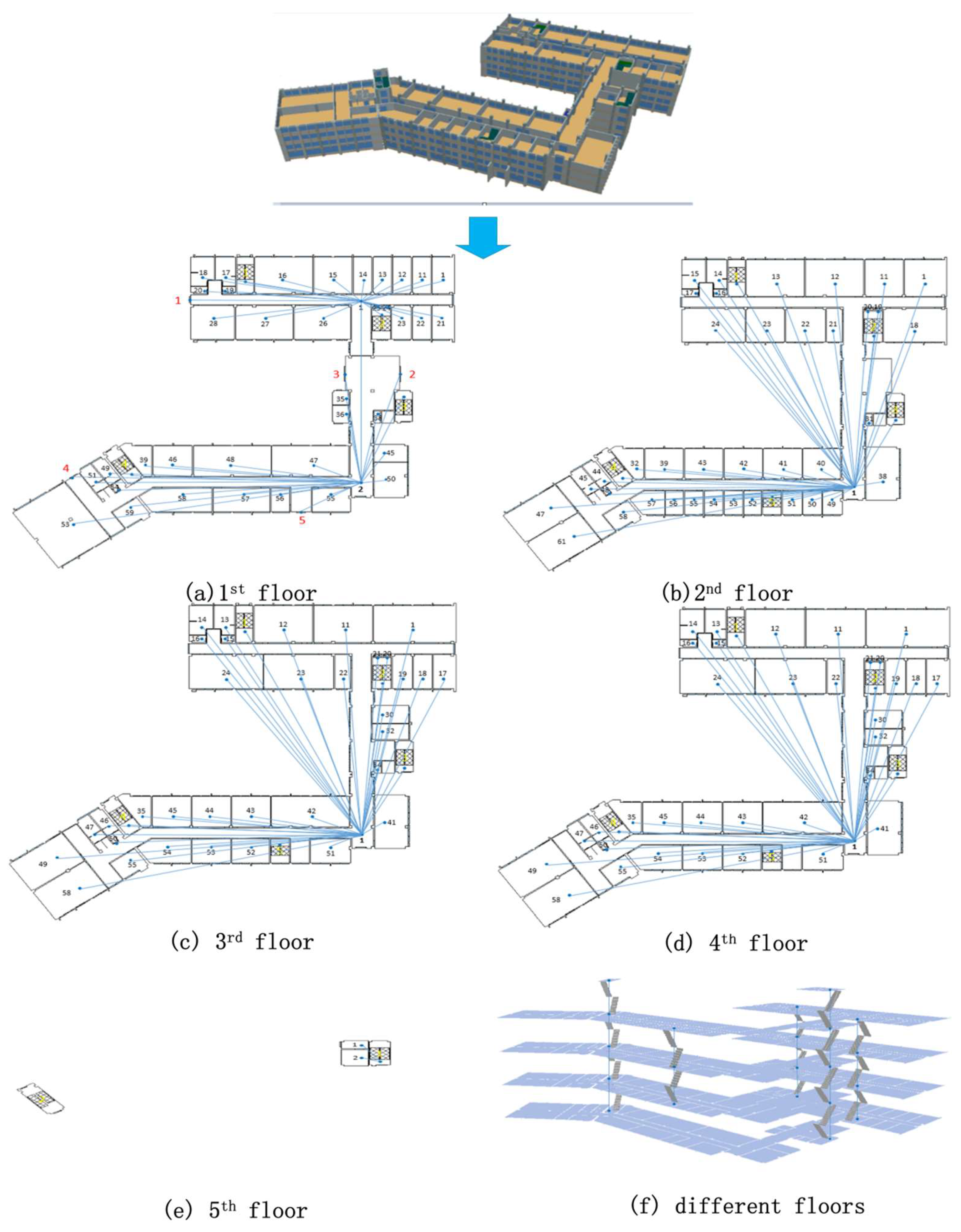
Figure 6.
Classification of indoor space nodes.

Figure 7.
Per capita area under different conditions (adapted from [32]).
Figure 7.
Per capita area under different conditions (adapted from [32]).

Figure 8.
Flow of people between indoor spaces.

Figure 9.
Individual walking speeds for different conditions (adapted from [32]).
Figure 9.
Individual walking speeds for different conditions (adapted from [32]).
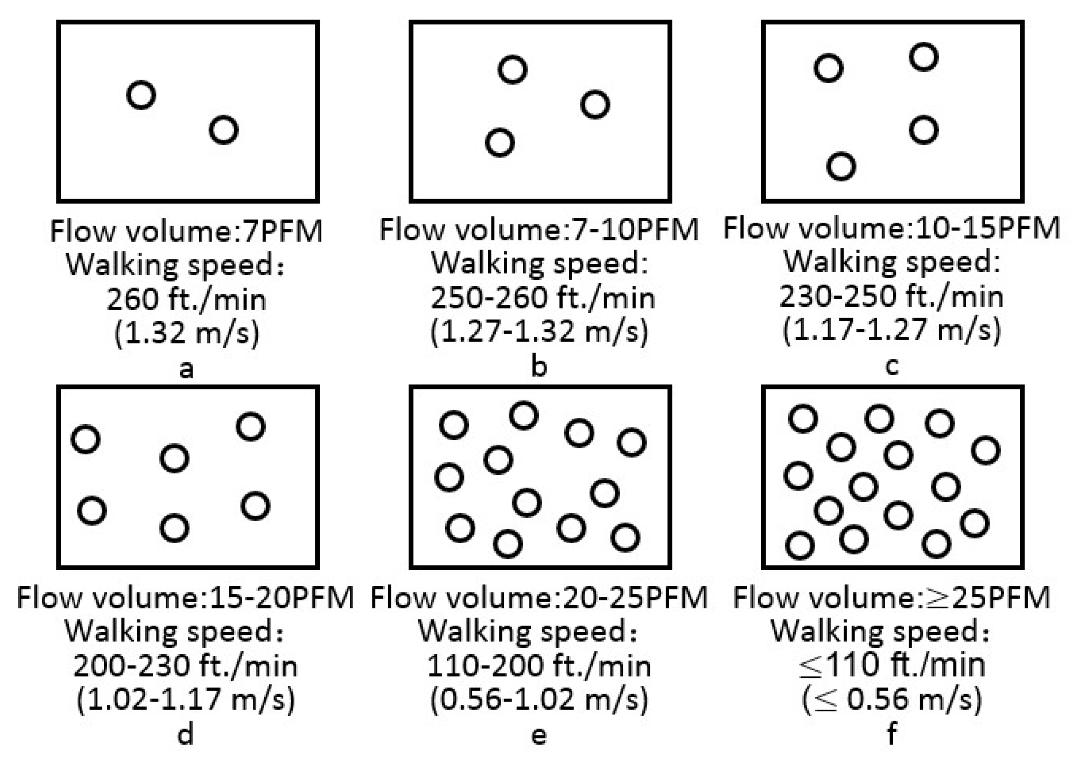
Figure 10.
Influence of numbers of similar sized doors on the passing ability.
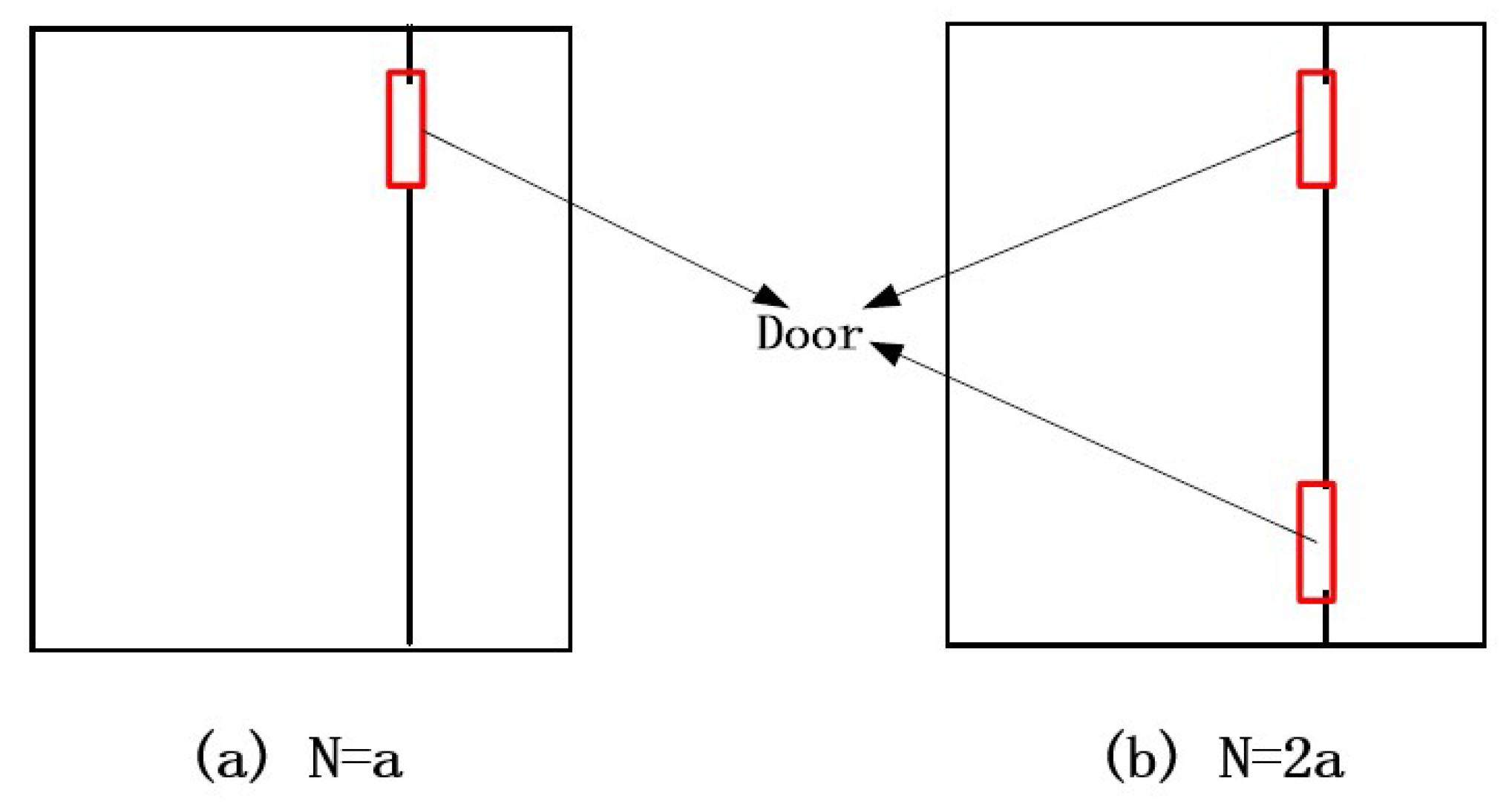
Figure 11.
Integration of the building data model and calculation results in GIS environment.
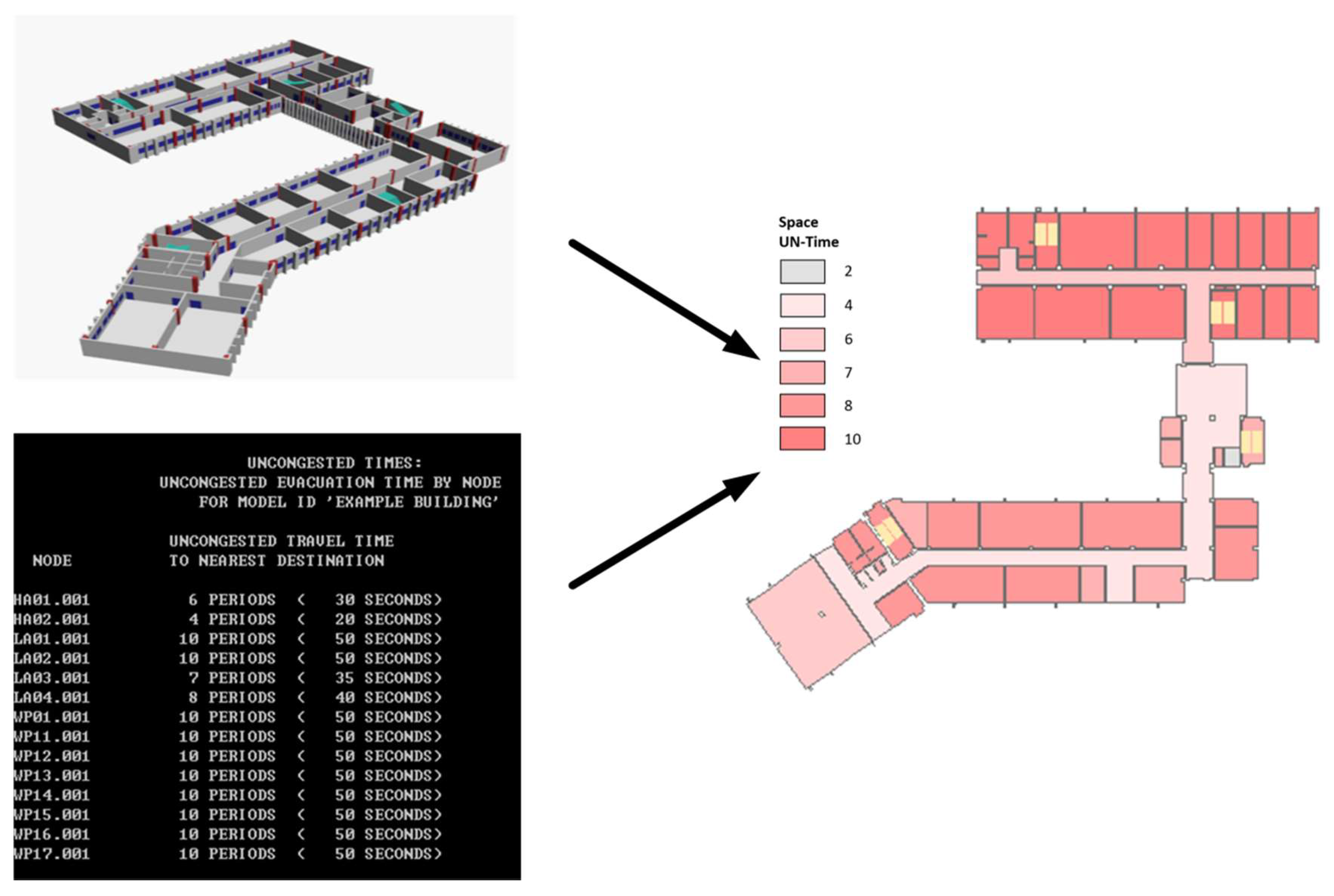
Figure 12.
IFC model of the Zhongbei Music Building.

Figure 13.
Input File of EVACNET4.

Figure 14.
Rooms with opened windows in the Zhongbei Music Building (operating condition 2).

Figure 15.
Generation of the network model on first floor.
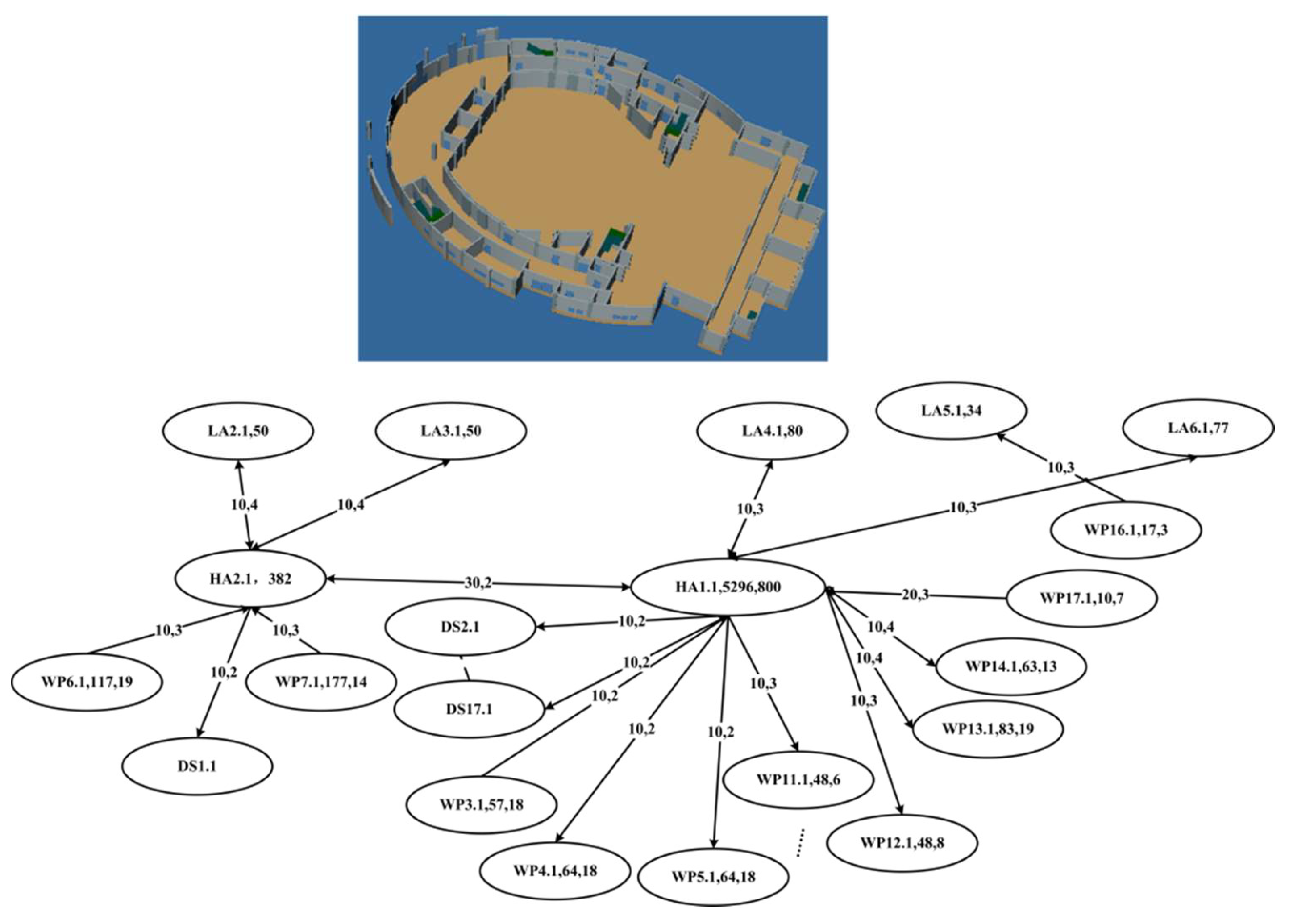
Figure 16.
Generation of the network model on second floor.

Figure 17.
Generation of the network model on third floor.
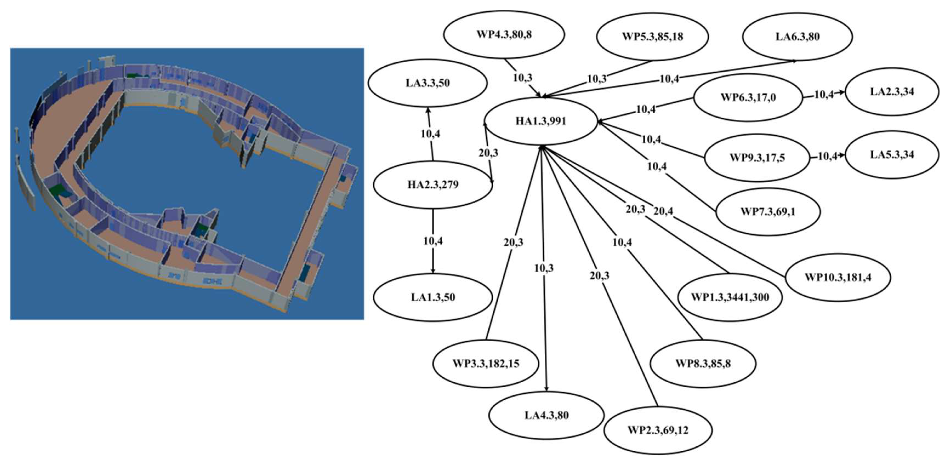
Figure 18.
Generation of the network model on fourth floor.
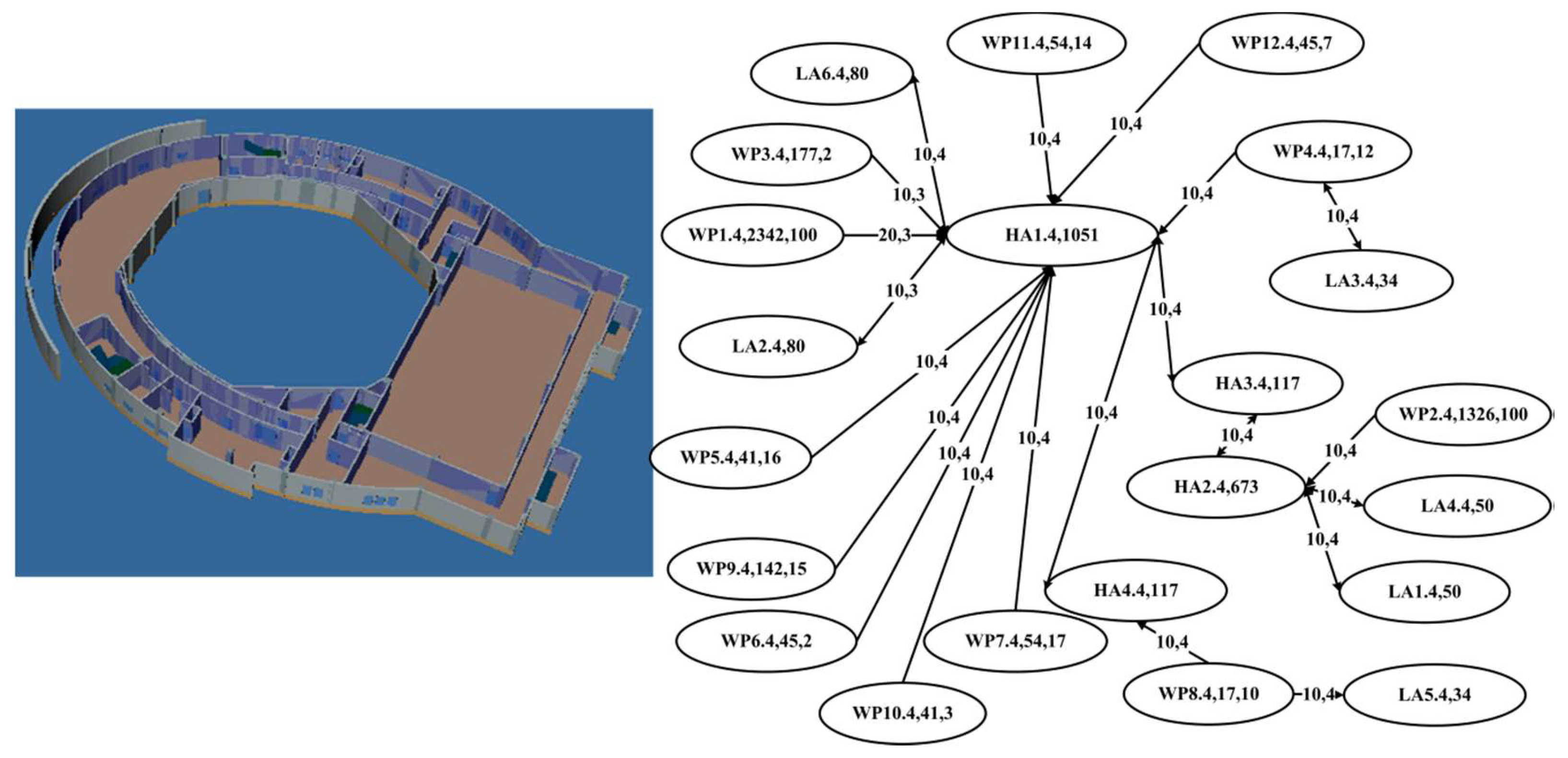
Figure 19.
Generation of the network model on fifth floor.

Figure 20.
EVACNET4 input file.

Figure 21.
Output of EVACNET4 and the 3D visualization (crowdedness degree and bottlenecks).

Figure 22.
Output of EVACNET4 and the 3D visualization (evacuation time).

Figure 23.
A comparison of the number of people in each space node for operating conditions 1 and 2.
Figure 23.
A comparison of the number of people in each space node for operating conditions 1 and 2.
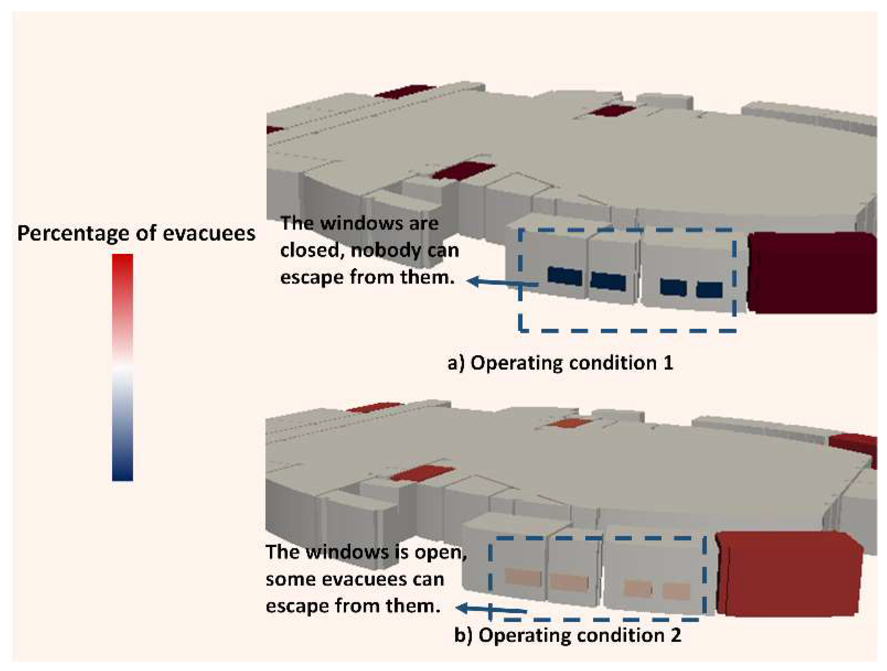
Figure 24.
Comparison of network structures for condition 1 and condition 2.

Table 1.
Semantic element types for an MNME.
| Element | Description | Type |
|---|---|---|
| Node | Inner space | Room |
| Corridor | ||
| Stairwell | ||
| Destination | ||
| Arc | Inner connections between spaces | Space connectivity with “doors” as passages |
| Space connectivity with “windows” as passages |
Table 2.
Classification of related attributes.
| Model | Node-and Arc-Related Attributes | Crowd-Related Attributes | Environment-Related Attributes |
|---|---|---|---|
| EXIT89 | node area, node height, and node distance, opening widths between nodes, etc. | age, sex, awake/asleep | smoke concentration, smoke thickness, hot upper layer, cool lower layer |
| EVACNET4 | opening widths between nodes, node distance. | passing ability, passing time, flow direction, initial occupants, capacity | |
| Takehashi et al.’s Model | room length, room width, state of openings (open/closed) | response time, walking speed | |
| BGRAF | state of openings (open/closed) | response time, familiarity with floor, awake/asleep | fire source position, speed of smoke, speed of fire |
Table 3.
Extraction of related attributes for nodes and arcs.
| Attribute Type | Extraction Method |
|---|---|
| Node (room) area, height, length, and width |
|
| Opening height, width |
|
| Distance between nodes |
|
Table 4.
Extraction method for crowd-related attributes.
| Attribute Type | Extraction Method |
|---|---|
| Passing ability, passing time, flow direction, capacity, walking speed, initial occupants | These attributes can be calculated based on the geometric information of nodes and arcs, and on related empirical formulae (the detailed method is described below). |
| Age, sex, awake/asleep, response time, familiarity with floor | These can be set according to the operating conditions. |
Table 5.
Node type definitions.
| Node Type | Room | Corridor | Staircase | Staircase | Hall | Destination | Elevator |
|---|---|---|---|---|---|---|---|
| Definition | WP | HA | LA | SW | LO | DS | EL |
© 2018 by the authors. Licensee MDPI, Basel, Switzerland. This article is an open access article distributed under the terms and conditions of the Creative Commons Attribution (CC BY) license (http://creativecommons.org/licenses/by/4.0/).
Share and Cite
MDPI and ACS Style
Zhu, Z.; Zhou, L.; Zhang, C.; Lin, B.; Cui, Y.; Che, M. Modeling of Macroscopic Building Evacuation Using IFC Data. ISPRS Int. J. Geo-Inf. 2018, 7, 302. https://doi.org/10.3390/ijgi7080302
AMA Style
Zhu Z, Zhou L, Zhang C, Lin B, Cui Y, Che M. Modeling of Macroscopic Building Evacuation Using IFC Data. ISPRS International Journal of Geo-Information. 2018; 7(8):302. https://doi.org/10.3390/ijgi7080302
Chicago/Turabian StyleZhu, Zhenhao, Liangchen Zhou, Chi Zhang, Bingxian Lin, Ying Cui, and Mingliang Che. 2018. "Modeling of Macroscopic Building Evacuation Using IFC Data" ISPRS International Journal of Geo-Information 7, no. 8: 302. https://doi.org/10.3390/ijgi7080302
Note that from the first issue of 2016, this journal uses article numbers instead of page numbers. See further details here.