Design of a Lockable Spherical Joint for a Reconfigurable 3-URU Parallel Platform


Department of Industrial Engineering and Mathematical Sciences, Polytechnic University of Marche, 60131 Ancona, Italy
*
Author to whom correspondence should be addressed.
Robotics 2018, 7(3), 42; https://doi.org/10.3390/robotics7030042
Submission received: 13 June 2018
/
Revised: 14 July 2018
/
Accepted: 30 July 2018
/
Published: 2 August 2018
(This article belongs to the Special Issue Kinematics and Robot Design I, KaRD2018)
Abstract
:This article deals with the functional and preliminary design of a reconfigurable joint for robotic applications. Such mechanism is a key element for a class of lower mobility parallel manipulators, allowing a local reconfiguration of the kinematic chain that enables a change in platform’s mobility. The mechanism can be integrated in the kinematic structure of a 3-URU manipulator, which shall accordingly gain the ability to change mobility from pure translation to pure rotation. As a matter of fact, special kinematics conditions must be met for the accomplishment of this task. Such peculiar requirements are described and properly exploited for the design of an effective reconfigurable mechanism. A detailed description of the joint operational principle is provided, also showing how to design it when is physically located at the fixed base of the manipulator.
1. Introduction
Reconfigurable manipulators may represent an answer to the request of flexibility in the nowadays manufacturing industry. A reconfigurable or metamorphic manipulator is a machine that is able to change its end-effector mobility according to a local change of kinematics. Several methods can be used to modify the kinematic structure of a manipulator; the most common one is the use of lockable joints, i.e., joints with some degrees of freedom (DOF), one of which can be selectively locked in order to reconfigure the resulting mobility. The family of Parallel Kinematics Machines (PKMs) in particular can significantly take profit by the development of reconfigurable joints since a little modification of legs kinematics may lead to substantial modifications of the global mobility. The limited availability of a dextrous workspace is one of the major drawbacks of PKMs, therefore the possibility of locally (or temporarily) modifying the motion capabilities of a particular kinematic structure can trigger a significant interest.
As is well known, many closed loop joints’ topologies, typical of PKMs, can present several assembly or working modes, often characterized by different motion capabilities, corresponding to different branches of the solution robot’s kinematics [1,2,3]. It results that the exploitation of two, three, or even more assembly modes of a parallel kinematic machine could enormously enhance its usability in an industrial application. Some studies focused on the possibility of modifying robot mobility by changing the assembly mode but avoiding the disassembly of the manipulator [4,5,6,7,8]. Further attention has been paid to temporary modification of the kinematics structure, aimed at exploitation of the superior capabilities of under-actuated redundant structures: in such cases a lockable joint properly actuated during motion can improve the ability of performing positioning tasks [9,10,11]. Moreover, the typical modularity of serial robots can be searched also in reconfigurable PKMs [12,13], where a combination of elemental branches, sometimes provided with lockable joints, can be exploited to assemble manipulators characterized by different motion capabilities. Moreover, a 6-DOF full mobility parallel robot equipped with six motors can also take advantage of lockable joints to behave like a legged manipulator [14], which can perform six-axis machining operations but also walk and reach other working stations. Scientific literature already provides few examples of lockable joints [15,16,17,18,19]; in particular, multiple DOF’s kinematic pairs are obtained by the composition of elementary kinematic pairs which are then locked alternately; however, the change of configuration of the joints is often managed manually, without taking care of the behaviour of the manipulator during the transition. In fact, it may happen that the robot passes through an under-constrained configuration, temporarily gaining degrees of freedom: in this case, only an external manual support allows for holding the robot in its pose.
The researchers at the Robotics Lab of the Polytechnic University of Marche in Ancona (Italy) in recent years developed several studies on reconfigurable robots exploiting the concept of lockable joints. Firstly, they focused on the Cylindrical-Prismatic-Universal three legged architecture (3-CPU): it allows the design of a reconfigurable tripod able to perform pure translational or pure rotational motions, depending on the orientation of the axes of the universal joints [20,21]. The switch between the two mobilities by means of a lockable joint was then faced in [22]. Notwithstanding the discussed metamorphic capabilities, the 3-CPU architecture also owns some intrinsic drawbacks. In particular, the main issue that affects such architecture is the need of reconfiguring the passive joints which connect the end-effector to limbs structure: it implies that the lockable mechanism must be part of leg structure, thus making more complex the mechanical design (for the limitation of weight and size of the device) and leading a reduction of the payload.
Consequently, the authors studied different topologies, which have in common with the 3-CPU manipulator the same types of mobilities [23] among them the 3-URU (Universal-Revolute-Universal) architecture was selected to design a novel reconfigurable manipulator [24,25]. The 3-URU manipulator can be derived from the 3-SRU (Spherical-Revolute-Universal) topology: the spherical joint connecting the leg to the fixed platform can be thought as the composition of three revolute joints with concurrent axes; locking one of them selectively, the joint turns into a universal joint with different sequences of rotations. Two of the possible sequences, as described in the following section, provide the mobile platform with the capability to yield motions of pure rotation and pure translation respectively.
2. The 3-URU Reconfigurable Robot
The main scope of this manuscript is to introduce a novel lockable spherical joint, designed to manage the reconfiguration capabilities of a 3-SRU under-actuated parallel kinematics machine. Such joint is realized as a combination of revolute pairs (see Figure 1); a locking system allows for alternatively locking one of the first two revolute joints, giving the machine different 3-URU kinematic configurations which correspond to different types of mobility. For a deeper understanding of how the joint will affect the robot mobility, a description of its structure is provided in the following.
The kinematic architecture of each leg is composed of a Spherical-Revolute-Universal (SRU) joints chain. The spherical pair, which must be reduced to a universal joint in order to guarantee the functionality of the machine, connects the first body of each leg to the chassis. The second link is connected to the first one by a revolute joint. At last, a universal joint connects the end-effector to the leg. The mutual arrangement of the joints, which is of great importance for the mobility of the moving platform, is shown in Figure 1. As visible, the three spherical pairs are located so that their centers lie on the axes of the fixed reference frame at the same distance, called a, from the origin. The three rotations that compose each pair are realized by three perpendicular revolute joints, whose axes concur in a point (namely the center of the spherical pair). At such point, three reference frames have a common origin: such frames, called , , for the i-th leg, are fixed to the bodies sequentially connected to the three revolute joints. In the home configuration, Figure 1, where the mobile platform frame is coincident with the fixed frame , it is . Given the description of local frames, the disposition of the three axes composing the spherical joint can be defined as follows:
- -
- the first revolute joint is coaxial to the respective axis of the reference frame . In the i-th leg local frame the unit vector describing such axis is ;
- -
- the second revolute joint is perpendicular to the first one and it is directed along the first body of the limb at home configuration. In the frame it is ;
- -
- the axis of the third and last rotation is perpendicular to both axes of the first and the second rotations at home configuration. With respect to frame it is .
The locking mechanism is used in this case to produce two different configurations, here called Joints Configuration A and Joints Configuration B (see Figure 1). In configuration A, the first rotation of the spherical pair is allowed and, in particular, it represents the actuated degree of freedom of the i-th leg. The second rotation is locked, while the third one is free. In configuration B, the first rotation is locked, the second one is actuated and the third one is free. As demonstrated in [24,25], such joints setting allows the generation of motions of pure rotation with Joint Configuration A and motions of pure translation with Joint Configuration B without further modification to the arrangement of the passive joints.
The rest of the kinematic chain of each leg is composed by a revolute joint, parallel to the last revolute pair of the reconfigurable spherical joint at a distance b, and by a universal joint that connects the second link of the leg to the end-effector. As demonstrated by Palpacelli et al. in [23], the arrangement of the last joint of the chain is also crucial for the definition of end-effector’s mobility. In particular, for the reconfigurable 3-URU parallel robot, the last universal joint is arranged so that the first rotation is parallel to previous revolute joint at a distance c, thus it is perpendicular to the leg plane (identified by points , , and ). The second rotation lies on and is perpendicular to the previous one; on the end effector, such axes are mutually perpendicular and concurrent at the origin of the moving frame . Moreover, such axes coincide with the axes of . With respect to such reference frame, the three attachment points are identified by vectors , , and .
The locking mechanism is designed so as to allow alternatively the motion of the first and the second revolute joint. A similar solution was already proposed by authors in [25] for the reconfiguration of a 3-CPU robot. Nonetheless, the mechanical solution proposed in the present article is significantly different since previous design was used to modify the mobility of a passive universal joint. In the present case, instead, the reconfiguration implies that the actuated joints of the robot must be changed. The mechanical design of the reconfigurable joint is obviously affected by that. On the one hand, the need of connecting an actuator to different joints relatively complicates the problem. On the other hand, the fact that the lockable device is attached at the ground frame and it is not moving together with the end effector relaxes the design parameters in terms of weight and dimension, and consequently in terms of costs.
3. Conceptual Design of the Reconfigurable Joint
The conceptual design is based on a bevel gear coupling, as shown in Figure 2. Such solution is similar to the one proposed by the authors in [23]. However, the present locking mechanism has been re-conceived in order to allow the actuation of the bevel gear D, which must be connected to the motor. The motion of the sliding cursor C reconfigures the spherical joint alternatively locking one of the rotations of the spherical joint as described in the following paragraphs.
The cursor C is driven by an actuator in two different positions, which provide the joint as many different working modes. The cursor has a cylindrical shape with an external splined shaft and an internal splined hub at the top. In the Configuration A (Figure 2, top), the cursor C engages the splined hub of the fork B. In this case B, C and D globally behave like a rigid body. Due to that, the second fork E does not rotate with respect to B. The body F remains free to rotate since it is not constrained anyhow. Such configuration turns to allow rotations about axes x and y as required by the 3-URU of pure rotation.
If the cursor is moved downwards to Configuration B (Figure 2, down), the splined shaft engages with both bodies A and B. As a consequence, the rotation of B remains locked. The rotation of the actuated bevel gear is transmitted instead to the second fork E, which now represents the actuated degree of freedom of the leg. Thus, configuration B allows an actuated rotation about axis z and a free rotation around y, exactly as required for the pure translation configuration.
4. Functional Design of the Reconfigurable Joint
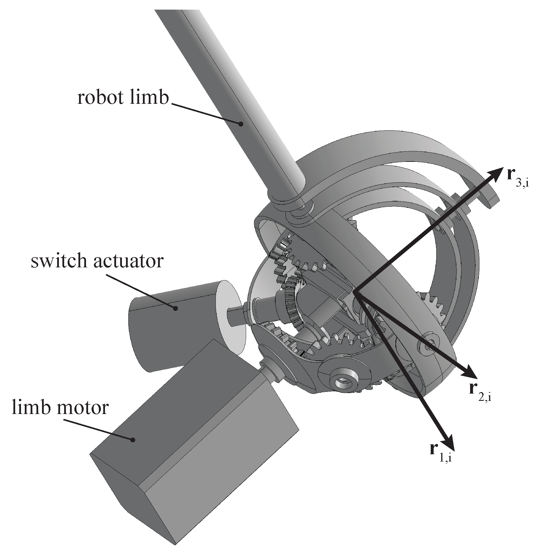
Starting from the concept described in the previous section, a functional mechanical design is here proposed and discussed. The exterior aspect of the joint is sketched in Figure 3. Both the actuator of the leg and the actuator of the switching cursor are located externally, fixed to the ground. This represents a crucially important aspect of the present version of the reconfigurable joint, which makes it a significantly enhanced version of the 3-URU reconfigurable device: in [22], the actuator was dedicated to reconfiguring a passive joint within the kinematic chain, with a series of consequent non-avoidable issues. Firstly, the actuator was moved around in the robot workspace, solidly with the last joint of the leg (thus solidly with the robot end-effector). On the other hand, in the 3-URU case study, there was no need to actuate the reconfigured degree of freedom.
Such considerations led to a different functional design of the spherical joint, based on a series of spherical links connected by a system of gears, as described in this section. Globally, the mobility is characterized by a rotation of the limb around that is always free; such rotation is preceded by a first rotation, whose axis can be selected among or acting on the switch.
4.1. The Operational Principle
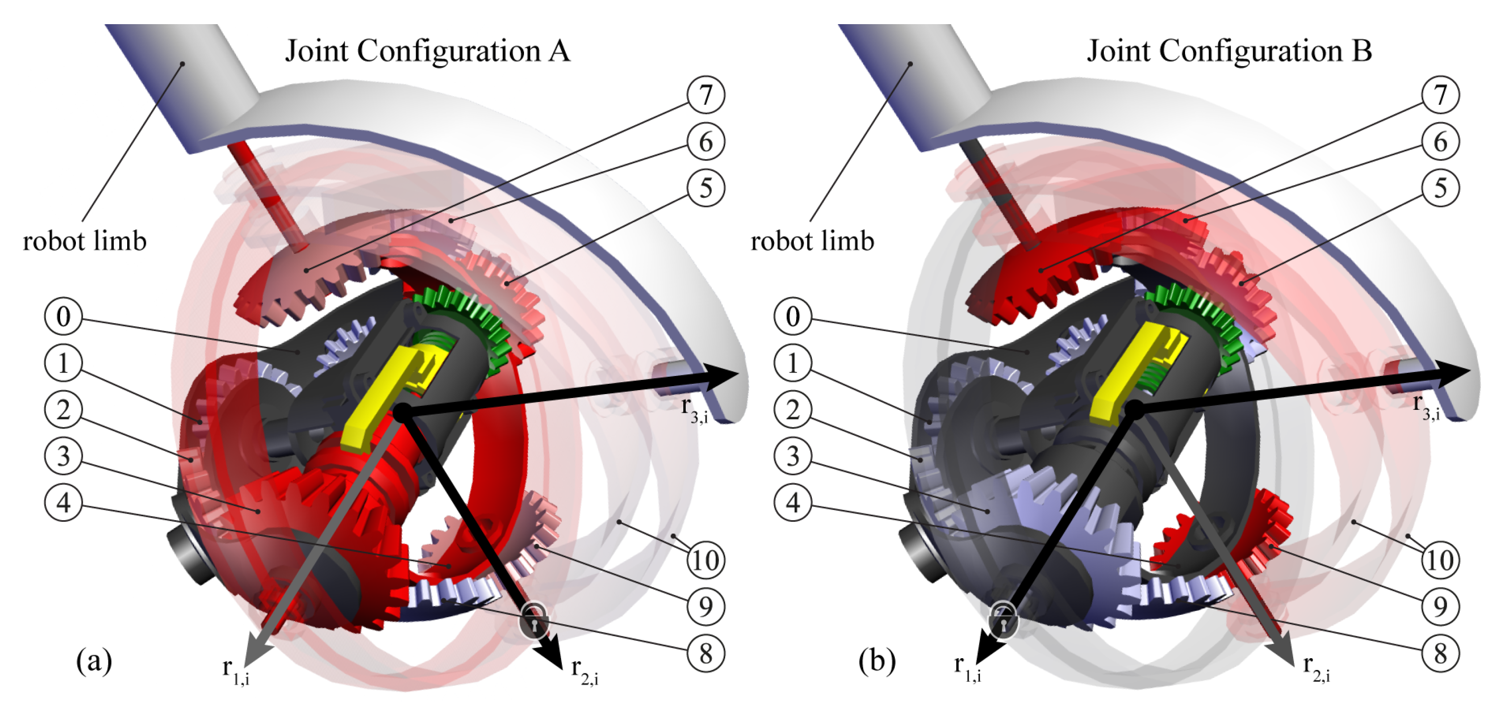
The joint exploits some bevel gear couplings, as in a previous concept; nevertheless, the rise of new additive manufacturing technologies for fast prototyping of small custom-made parts pushed the authors to adopt different shapes for the design of such gears. In particular, the classical bevel gears previously adopted were extremely binding in terms of dimension and assembly. Thus, a different solution has been adopted with gears obtained from spherical shells in order to maximize the room available within the gears coupling; such space can be used to accommodate the switching cursor. Th components of the joint are assembled on different layers, as shown in Figure 4.
The following lines, making reference to Figure 4a, explain how the reconfigurable joint works:
- -
- Joints Configuration A, Figure 4a: the actuator of the limb is fixed to the grounded body 0 (dark grey in figure) and it is connected to the bevel gear 1 which moves gears 2 and 3. In this configuration, the locking mechanism, which is described later, solidly connects the gear 3 to the body 4 (colored in red in Figure 4a). Thus, the rotation of gear 3 moves the robot limb around the axis , as required by Joints Configuration A. The gear 5, which rotates solidly with 3, does not affect the mobility since it is not connected to the body 4, as well as gears 6, 7, 8, and 9. The rotation around axis is restricted by the fact that gears 7 and 9 are always solid with the fork 10. Such gears rotate around by means of the motion of body 4, avoiding them to rotate around their own axes. Rotation about is no way controlled, as required by the robot kinematics.
- -
- Joints Configuration B, Figure 4b: in this configuration, the locking mechanism connects the body 4 to the ground 0, avoiding the rotation around . The actuation starts again from gear 1 and it is transmitted to 2, 3 and then to 8 and 9. In this case, the rotation of gear 9 puts in rotation the fork 10 around , as prescribed by the kinematics required by joints configuration B. Gears 5, 6 and 7 work exactly in the same way providing a symmetric actuation to the fork 10. Again, rotation about is no way controlled.
4.2. The Locking Mechanism
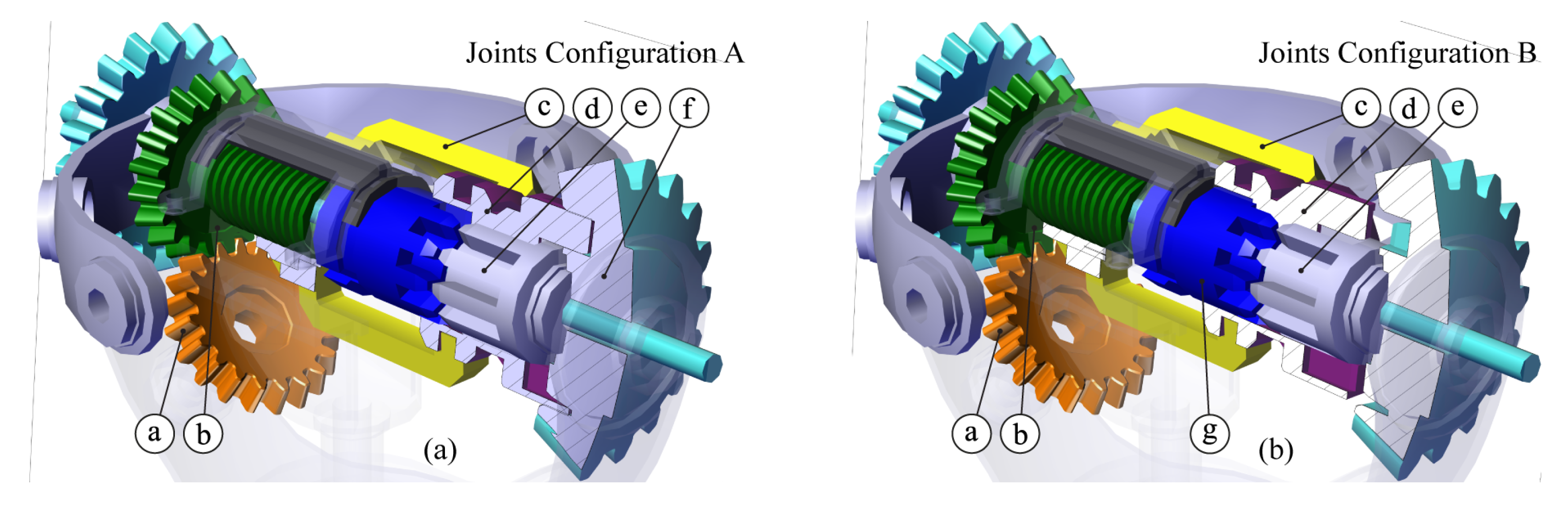
The whole functionality of the reconfigurable joint is based on a locking mechanism which is able to alternatively lock body 4 to the bevel gear 3 (Joints Configuration A) or to ground 0 (Joints Configuration B). Such mechanism, which is shown in detail in Figure 5 for both joints configurations A and B, is operated as follows:
- -
- Joints Configuration A, Figure 5a: the actuation of the locking mechanism comes through the bevel gear a, which moves the gear b, solidly connected to a screw. Such screw puts into translation a nut connected to the fork c which pushes the cursor d. The aim of such body is that of constraining the splined shaft e together with the bevel gear f, whose function has already been explained previously (see gear 3 in Figure 4a). It should be noted that the splined shaft e is a part of the body indicated with the number 4 in Figure 4a.
- -
It is worth mentioning that the locking mechanism shall be moved by a dedicated actuator which must be as simple as possible. The particular task it shall fulfill, in fact, is just to rotate the gear a through two given positions, for it is not necessary to assume intermediate poses. As a consequence, a simple rotational pneumatic, hydraulic, or solenoid binary actuator will accomplish the purpose without considerably affecting the cost of the whole robot.
5. Conclusions
The article has described the functional design of a reconfigurable universal joint. A switching cursor, which can be driven electronically, is used to change the joint configuration so that two different universal joints can be obtained. Such feature can be exploited to realize a reconfigurable 3-URU manipulator, in which the three universal joints at the fixed base are reconfigurable. A gear system is proposed as a mechanical solution to allow an effective and reliable change of the joint configuration. Future works will be focused on the structural design of the joint, in order to properly design all components in terms of dimensions and materials; such study will start from the static and dynamic analysis of the whole manipulator, in order to assess the forces acting on the joint. In that phase, the joint parts and gears will be also manufactured by rapid prototyping, with the aim of testing their strength and accuracy when assembled in a whole device.
Author Contributions
Conceptualization, L.C. and M.P.; Writing—Original Draft Preparation, G.P.; Supervision, M.C.; Project Administration, M.P.
Funding
This research received no external funding.
Conflicts of Interest
The authors declare no conflict of interest.
References
- Chablat, D.; Wenger, P. Working modes and aspects in fully parallel manipulators. In Proceedings of the IEEE 1998 International Conference on Robotics and Automation, Leuven, Belgium, 20–20 May 1998; Volume 3, pp. 1964–1969. [Google Scholar]
- Chablat, D.; Kong, X.; Zhang, C. Kinematics, workspace and singularity analysis of a multi-mode parallel robot. In Proceedings of the ASME 2017 International Design Engineering Technical Conferences and Computers and Information in Engineering Conference, Cleveland, OH, USA, 6–9 August 2017; Volume 5A. [Google Scholar]
- Au, W.; Chung, H.; Chen, C. Path planning and assembly mode-changes of 6-DOF Stewart-Gough-type parallel manipulators. Mech. Mach. Theory 2016, 106, 30–49. [Google Scholar] [CrossRef]
- Tian, C.; Fang, Y.; Guo, S.; Qu, H. A class of reconfigurable parallel mechanisms with five-bar metamorphic linkage. Proc. Inst. Mech. Eng. Part C 2017, 231, 2089–2099. [Google Scholar] [CrossRef]
- Gan, D.; Dai, J.; Dias, J.; Seneviratne, L. Reconfigurability and unified kinematics modeling of a 3rTPS metamorphic parallel mechanism with perpendicular constraint screws. Robot. Comput. Integr. Manuf. 2013, 29, 121–128. [Google Scholar] [CrossRef]
- Khalid, A.; Mekid, S. Design synthesis of a three legged SPS parallel manipulator. In Proceedings of the 36th International MATADOR Conference, Manchester, UK, 14–16 July 2010; pp. 169–173. [Google Scholar]
- Ye, W.; Fang, Y.; Guo, S. Structural synthesis of a class of metamorphic parallel mechanisms with variable mobility. In Advances in Reconfigurable Mechanisms and Robots I; Springer: London, UK, 2012; pp. 119–126. [Google Scholar]
- Finistauri, A.; Xi, F. Reconfiguration analysis of a fully reconfigurable parallel robot. J. Mech. Robot. 2013, 5, 041002. [Google Scholar] [CrossRef]
- Grosch, P.; Di Gregorio, R.; López, J.; Thomas, F. Motion planning for a novel reconfigurable parallel manipulator with lockable revolute joints. In Proceedings of the IEEE 2010 International Conference on Robotics and Automation (ICRA), Anchorage, AK, USA, 3–7 May 2010; pp. 4697–4702. [Google Scholar]
- Taherifar, A.; Alasty, A.; Salarieh, H.; Boroushaki, M. Path planning for a hyper-redundant manipulator with lockable joints using PSO. In Proceedings of the First RSI/ISM International Conference on Robotics and Mechatronics (ICRoM), Tehran, Iran, 13–15 February 2013; pp. 224–229. [Google Scholar]
- Aukes, D.; Heyneman, B.; Ulmen, J.; Stuart, H.; Cutkosky, M.; Kim, S.; Garcia, P.; Edsinger, A. Design and testing of a selectively compliant underactuated hand. Int. J. Robot. Res. 2014, 33, 721–735. [Google Scholar] [CrossRef]
- Xi, F.; Li, Y.; Wang, H. A module-based method for design and analysis of reconfigurable parallel robots. In Proceedings of the International Conference on Mechatronics and Automation (ICMA), Xi’an, China, 4–7 August 2010; pp. 627–632. [Google Scholar]
- Zhang, T.; Zhang, W.; Gupta, M. An underactuated self-reconfigurable robot and the reconfiguration evolution. Mech. Mach. Theory 2018, 124, 248–258. [Google Scholar] [CrossRef]
- Yang, H.; Baradat, C.; Krut, S.; Pierrot, F. An agile manufacturing system for large workspace applications. Int. J. Adv. Manuf. Technol. 2016, 85, 25–35. [Google Scholar] [CrossRef]
- Zhang, W.J. A new class of linkage with synthesis method for exact dwell motion at 1 and/or 2 limit positions of output link. In Proceedings of the 24th ASME Mechanisms Conference, Irvine, CA, USA, 18–22 August 1996; pp. 1–5. [Google Scholar]
- Chen, W.; Zhang, J.; Quan, J.; Lv, T. A novel spherical joint designed for metamorphic mechanism. In Proceedings of the 2008 IEEE Conference on Robotics, Automation and Mechatronics, Chengdu, China, 21–24 September 2008; pp. 976–981. [Google Scholar]
- Gan, D.; Dai, J.; Dias, J.; Seneviratne, L. Reconfiguration and static joint force variation of a 3rRPS metamorphic parallel mechanism with 3R and 1T2R motion. Mech. Mach. Sci. 2016, 36, 213–222. [Google Scholar]
- Zhang, T.; Zhang, W.J.; Gupta, M.M. A Novel Docking System for Modular Self-Reconfigurable Robots. Robotics 2017, 6, 25. [Google Scholar] [CrossRef]
- Yuan, C.W.; Yin, R.X.; Zhang, W.J.; Chen, G. A new under-actuated resilient robot. In Proceedings of the 2017 IEEE International Conference on Systems, Man, and Cybernetics (SMC), Banff, AB, Canada, 5–8 October 2017; pp. 1202–1207. [Google Scholar]
- Carbonari, L.; Callegari, M. The kinematotropic 3-CPU parallel robot: Analysis of mobility and reconfigurability aspects. In Latest Advances in Robot Kinematics; Springer: Berlin, Germany, 2012; pp. 373–380. [Google Scholar]
- Carbonari, L.; Callegari, M.; Palmieri, G.; Palpacelli, M.C. A new class of reconfigurable parallel kinematic machines. Mech. Mach. Theory 2014, 79, 173–183. [Google Scholar] [CrossRef]
- Palpacelli, M.C.; Carbonari, L.; Palmieri, G. Details on the design of a lockable spherical joint for robotic applications. J. Intell. Robot. Syst. 2016, 81, 169–179. [Google Scholar] [CrossRef]
- Palpacelli, M.; Carbonari, L.; Palmieri, G.; Callegari, M. Mobility analysis of non-overconstrained reconfigurable parallel manipulators with 3-CPU/3-CRU kinematics. In Advances in Reconfigurable Mechanisms and Robots II; Springer: Berlin, Germany, 2016; pp. 189–200. [Google Scholar]
- Carbonari, L.; Corinaldi, D.; Palpacelli, M.C.; Palmieri, G.; Callegari, M. Functional Design and Optimization of a Novel 3-URU Multimodal Reconfigurable Robot. In Proceedings of the ASME 2017 International Design Engineering Technical Conferences and Computers and Information in Engineering Conference, Cleveland, OH, USA, 6–9 August 2017; p. V009T07A050. [Google Scholar]
- Carbonari, L.; Corinaldi, D.; Palpacelli, M.; Palmieri, G.; Callegari, M. A novel reconfigurable 3-URU parallel platform. In Proceedings of the International Conference on Robotics in Alpe-Adria Danube Region, Torino, Italy, 21–23 June 2017; pp. 63–73. [Google Scholar]
Figure 1.
Setting of joints axes of the reconfigurable 3-URU kinematic architecture.
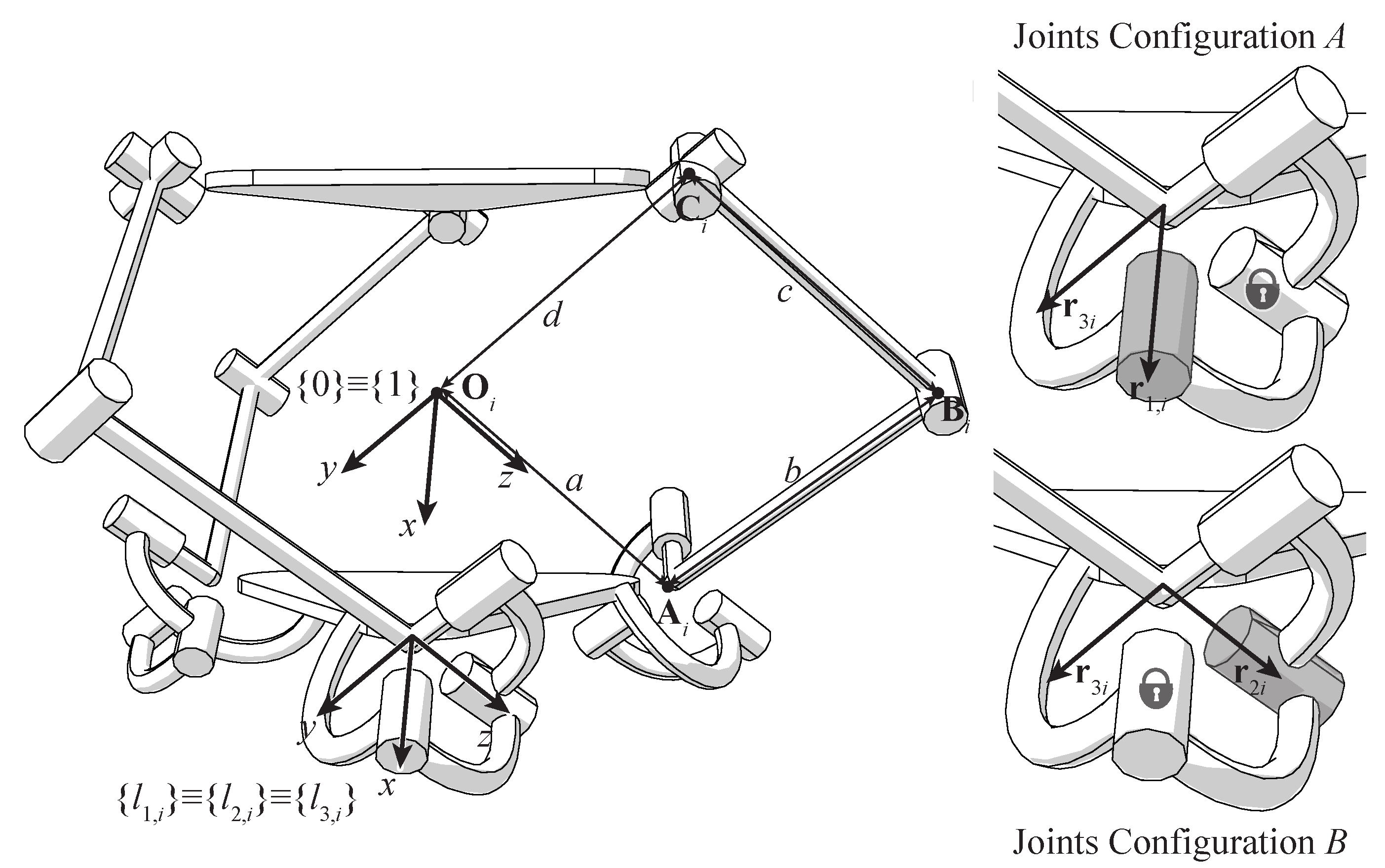
Figure 2.
Functional scheme of the reconfigurable joint for spherical (a) and translational (b) motions.
Figure 2.
Functional scheme of the reconfigurable joint for spherical (a) and translational (b) motions.

Figure 3.
Design of the reconfigurable joint.

Figure 4.
Details of the reconfigurable joint arranged for Joints Configuration A (a), and for Joints Configuration B (b).
Figure 4.
Details of the reconfigurable joint arranged for Joints Configuration A (a), and for Joints Configuration B (b).

Figure 5.
Nut-screw switching mechanism arranged for Joints Configuration A (a), and for Joints Configuration B (b).
Figure 5.
Nut-screw switching mechanism arranged for Joints Configuration A (a), and for Joints Configuration B (b).
© 2018 by the authors. Licensee MDPI, Basel, Switzerland. This article is an open access article distributed under the terms and conditions of the Creative Commons Attribution (CC BY) license (http://creativecommons.org/licenses/by/4.0/).
Share and Cite
MDPI and ACS Style
Palpacelli, M.; Carbonari, L.; Palmieri, G.; Callegari, M. Design of a Lockable Spherical Joint for a Reconfigurable 3-URU Parallel Platform. Robotics 2018, 7, 42. https://doi.org/10.3390/robotics7030042
AMA Style
Palpacelli M, Carbonari L, Palmieri G, Callegari M. Design of a Lockable Spherical Joint for a Reconfigurable 3-URU Parallel Platform. Robotics. 2018; 7(3):42. https://doi.org/10.3390/robotics7030042
Chicago/Turabian StylePalpacelli, Matteo, Luca Carbonari, Giacomo Palmieri, and Massimo Callegari. 2018. "Design of a Lockable Spherical Joint for a Reconfigurable 3-URU Parallel Platform" Robotics 7, no. 3: 42. https://doi.org/10.3390/robotics7030042
Note that from the first issue of 2016, this journal uses article numbers instead of page numbers. See further details here.