Omnidirectional Nonprehensile Manipulation Using Only One Actuator

Department of Mechanical Engineering, Graduate School of Engineering, Osaka University, Suita 565-0871, Japan
*
Author to whom correspondence should be addressed.
Robotics 2018, 7(3), 34; https://doi.org/10.3390/robotics7030034
Submission received: 1 May 2018
/
Revised: 26 June 2018
/
Accepted: 3 July 2018
/
Published: 4 July 2018
Abstract
:This paper presents a novel nonprehensile manipulation method that uses the vibration of a plate, where the two degrees of freedom of a part on the plate are controlled by only one actuator. First, a manipulator whose end effector is a flat plate is introduced. By employing an underactuated joint mechanism, the shape and orientation of the vibrational orbit of the plate vary according to frequency and offset angle of the sinusoidal displacement input to an actuator. Then, simulation analyses reveal that the manipulator can omnidirectionally induce translational velocity to the part on the plate. There exists an orthogonality between the effects of the frequency and offset angle on the velocity map of the part. Based on this characteristic, a visual feedback control for manipulating the part is designed. Finally, the proposed method is validated via experiments using a prototype manipulator. A target-trajectory tracking task and a four-way part-feeding task are demonstrated.
1. Introduction
Robotic object manipulations include the grasping type, which employs multifingered hands [1]. This type has the advantage of higher dexterity and accuracy by using a large number of degrees of freedom (DoF) of the robot. Besides, robotic object manipulations include the nonprehensile type [2,3,4,5,6,7,8,9,10,11,12,13,14,15,16,17,18,19,20,21,22,23,24] shown in Figure 1a. Compared with the grasping type, the nonprehensile type has the advantage of simplicity from the viewpoints of its mechanism and control law. Although a simple flat plate is utilized as an end effector, the position and orientation of a part can be controlled. Thus, the nonprehensile type has a capability to be applied to generic part-feeding and part-sorting devices in industrial systems. Moreover, because such a type does not involve grasping or picking a part, the stress concentration and the damage on the part are small. This implies that the nonprehensile type is suitable for handling delicate parts, such as food products and biological tissues.
So far, various nonprehensile manipulation schemes have been proposed. A typical approach is to use fully actuated systems, where the number of actuators required for driving the plate is equal to or greater than the number of DoFs of the part to be controlled [2,3,4,5,6,7,8,9,10,11,12,13,14,15]. Figure 1a shows an example of two-DoF manipulation by two actuators, where the moving velocity of a part can be induced omnidirectionally by using the X-Y translational motion of the plate. In contrast, relatively few studies for nonprehensile manipulations with underactuated systems have been reported [16,17,18,19,20,21,22,23,24]. Generally, an underactuated system contributes to simplify hardware and to reduce the number of actuators and sensors installed. It has a potential for reducing the cost, weight and maintenance labor of robot systems utilized as a planar part-feeding and part-sorting device. Based on such a motivation, the authors’ group has discussed a nonprehensile manipulation scheme where the two-DoF manipulation is realized by only one actuator. The preliminary work [23] proposed an underactuated joint mechanism with viscoelasticity and a nonparallel axis layout. The mechanism was utilized to vibrate a horizontal plate. It was shown that the direction of the induced velocity of a part on the plate could be changed according to the vibrational input to an actuator. However, the direction of the induced velocity was limited, and the part could not move directly in particular directions. While the underactuated nonprehensile manipulation methods using one actuator were discussed [19,20,21,22,23,24], there was no method that can control the induced velocity of a part omnidirectionally. The current work attempts to introduce a new manipulator using the underactuated joint mechanism introduced in [23] and a control law that can produce omnidirectional velocity of the part, as shown in Figure 1b.
This paper presents a nonprehensile manipulation via plate vibration. A two-DoF translational manipulation scheme of a planar part using only one actuator is proposed. First, a model of a manipulator with a flat plate end effector is introduced. The manipulator employs an underactuated mechanism composed of an actuator-driven active joint and a passive viscoelastic joint. The two joint axes are nonparallel to each other. A significant feature of this mechanism is that the vibrational orbit of the plate varies according to the sinusoidal displacement input to the actuator. Then, through simulation analyses, the velocity map that is drawn by the induced velocity vectors of the part by changing two input parameters, the frequency and offset angle of the sinusoidal displacement, is investigated. It is revealed that the manipulator can produce an arbitrary velocity of the part omnidirectionally. An interesting observation is that there exists a zero velocity point led by certain input parameters. In the neighborhood of the zero velocity point, orthogonality between the effects of the frequency and offset angle on the induced velocity is shown. Based on the above characteristics, a visual feedback control for omnidirectionally manipulating the part is designed. Finally, the proposed method is validated via experiments. A target-trajectory tracking task and a four-way part-feeding task are demonstrated.
The paper is organized as follows. In Section 2, related works are summarized. In Section 3, the model of the manipulator is introduced. In Section 4, the omnidirectionally induced velocity of the part is shown. In Section 5, the visual feedback control is designed. In Section 6, the experiments are described. Finally, Section 7 presents the conclusions of this study.
2. Related Works
Most of the conventional works of nonprehensile manipulation have involved fully actuated systems. Manipulation strategies wherein at most six-DoF motion of a part can be controlled by the plate attached to a six-DoF manipulator have been studied [2,3]. The universal planar manipulator (UPM), which consists of a horizontal plate with four linear motors was developed [4,5], and the three-DoF motion (two translational motions and one rotational motion) of a part was controlled. A flat plate manipulator with six speakers for vibrating the plate was developed, and it was shown that the three-DoF motion of a part can be controlled [6,7,8,9,10]. A one-DoF translational manipulation using a symmetric saw-tooth surface was proposed, in which micro-parts are transported using a single piezoelectric actuator [11,12,13,14]. A manipulation method using a surface on which the friction property varies depending upon the sliding direction of a part was discussed [15]. Underactuated nonprehensile manipulation has been employed in some studies. A manipulation scheme inspired by the handling of a pizza peel was proposed; in this scheme, the three-DoF motion of a part was controlled by a two-DoF plate [16,17,18]. The motion planning of the planar dynamic nonprehensile manipulation using a one-DoF manipulator was discussed [19]. In the vertical plane, the position and orientation of a part was controlled by using slipping, rolling, and free flight motions generated by the one-DoF manipulator. The manipulation method for the two-DoF positioning of a part based on the node of an elastic plate vibrated using a linear actuator was discussed [20,21,22]. In the above methods, the velocity of the part was not controlled. The authors proposed a manipulator equipped with an underactuated joint mechanism [23] that can change the direction of the induced velocity of a part on the plate by using one actuator. As described in Section 1, however, the direction of the induced velocity was limited. Employing the underactuated mechanism for generating non-horizontal dynamic plate motions, a different type of manipulator for positioning and orientating a part was developed [24]. In this method, however, the velocity of the part cannot be controlled. As far as we know, there was no manipulator that can control the induced velocity of a part omnidirectionally by using only one actuator as shown in Figure 1b.
3. Model of Manipulator
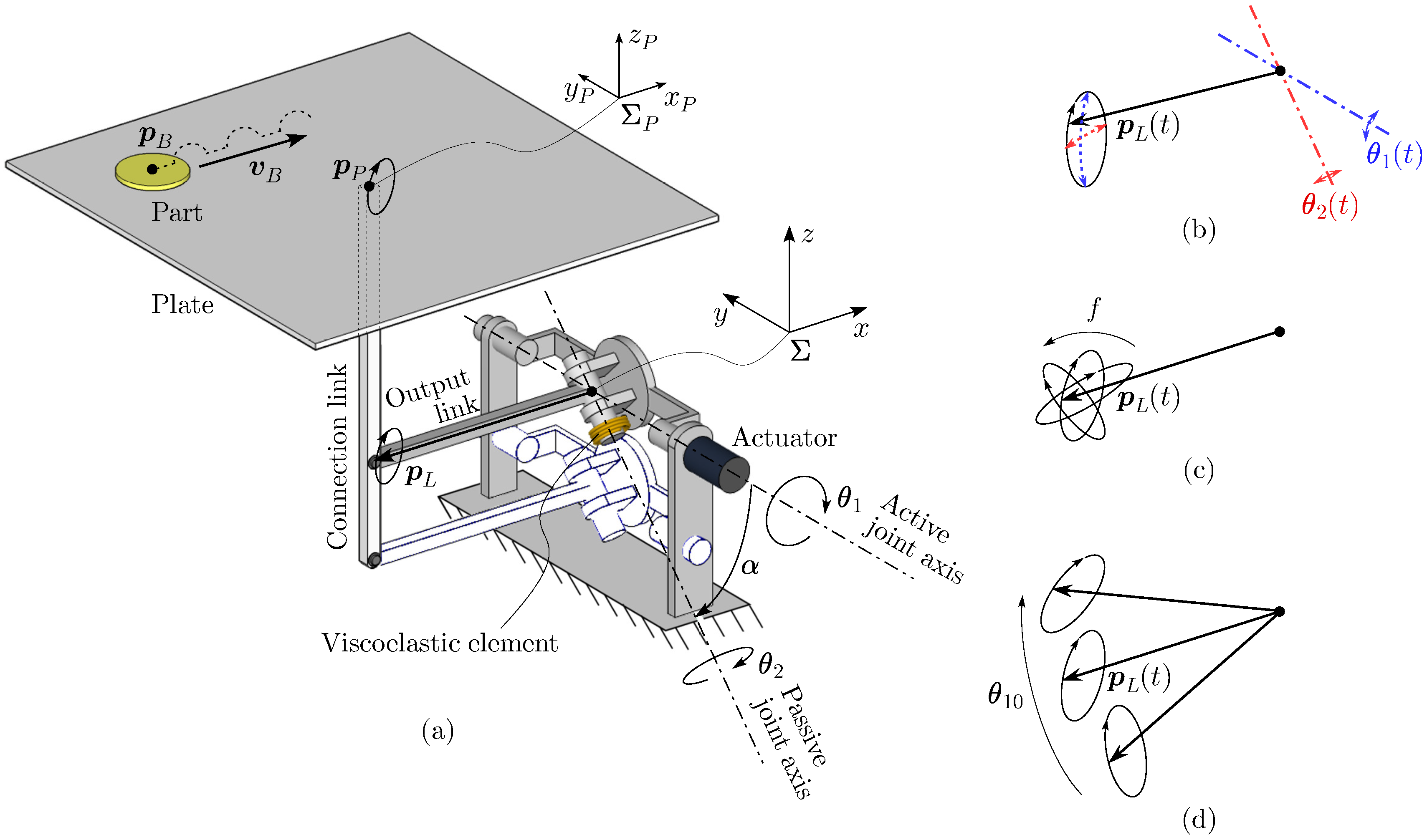
This section describes the model of a manipulator with a plate end effector, as shown in Figure 2a. The manipulator employs an underactuated joint mechanism and a parallel linkage. By the vibration of the plate, a part moves with sliding and jumping motions.
3.1. Underactuated Joint Mechanism
The underactuated joint mechanism [23] is installed to the manipulator. In the mechanism, an active joint driven by a rotary actuator and a passive joint equipped with a viscoelastic element are connected in series. Let and denote the angular displacements of the active and passive joint, respectively. The viscoelastic element, such as a torsion spring, generates the restoring and resistant torques with respect to the displacement and velocity of the passive joint. Its natural state is . A significant characteristic of this mechanism is that the two joint axes are arranged in a nonparallel manner in a common plane. Let denote the angle between the two axes. By the combination of the motions of the two joints, the tip of the output link, which is connected perpendicularly to the output shaft of the passive joint, moves on a spherical surface. Let denote the position vector of the tip of the output link with respect to the base coordinate system .
Suppose that an input command to the actuator is given so that the active joint traces a sinusoidal displacement with a small amplitude as follows:
where f, , and are the input frequency, offset angle, and amplitude, respectively. is the offset angle which is additionally given to the sinusoidal wave, and it determines the initial angle of inclination of the output link. In this case, owing to the inertial effect of the load at the tip of the output link, namely, the mass of the plate, the passive joint rotates. During steady-state vibration, the displacement of the passive joint is expressed as a sinusoidal wave, as follows:
where
is the frequency transfer function between the input and the output . and j denote the input angular frequency and the imaginary unit, respectively. is determined based on the angle , the natural angular frequency and damping ratio about the passive joint. As shown in Figure 2b, the tip of the output link draws an elliptic-like orbit by the combination of two sinusoidal joint motions and with the common frequency f. As shown in Equation (3), the amplitude and phase difference of the passive joint motion depend on the input frequency . This means that the shape, size, and orientation of the elliptic orbit of the tip of the output link vary with respect to the input frequency f, as shown in Figure 2c. The principle of changing the shape and orientation of elliptic orbit is identical to that of the Lissajous curve. In addition, the orientation of the orbit changes with respect to the offset angle while keeping its shape and size, as shown in Figure 2d. See [23] for details of the mathematical formulation of the dynamics and kinematics of the joint mechanism.
3.2. Vibrational Orbit of Plate and Manipulated Part
As shown in Figure 2a, a parallel linkage including the underactuated joint mechanism is employed. The parallel linkage includes a vertical connection link. A flat rigid plate is fixed at the tip of the connection link. Let denote the position vector indicating the connecting point between the plate and the connection link with respect to . Because of the parallel linkage, the plate maintains its horizontal posture and moves along the orbit given by the translating . Therefore, the shape, size, and orientation of the vibrational orbit of the plate are managed by two input parameters f and . Let us assume the following configurations: the active and passive joint axes are in the vertical plane and the active joint axis is horizontal. The output link is horizontal in the initial state with . The origin of the base coordinate system is located at the intersection of the two joint axes. The x axis and y axis are horizontal, and the z axis is vertical. The y axis corresponds to the active joint axis. In addition, the plate coordinate system is considered, with its origin located at the connecting point of the plate. The pose of is identical to that of .
On the vibrating plate, a planar part shows complicated motions including sliding and jumping, as shown in Figure 2a. The motion of the part varies depending upon the orbit of the plate . Therefore, there exists the possibility that the velocity of the part can be controlled by the two input parameters of the actuator, f and . Let and express the position and velocity vectors of the part with respect to , respectively. Note that, focusing on the position and velocity faced on the plate surface, the z directional components in and are omitted.
The following assumptions are considered to simplify the analysis:
- The actuator has sufficiently high power to guarantee that the active joint traces the required arbitrary trajectory.
- The gravitational torque acting on the passive joint is negligible compared to the restoring and resistance torques of the viscoelastic element.
- The mass of the part manipulated on the plate is small, and thus, it does not influence the orbit of the plate.
4. Omnidirectionally Induced Velocity of A Part
This section discusses the velocity of a part on the vibrating plate with respect to the input parameters to the actuator. Through the velocity map obtained by simulations, it is shown that the manipulator can induce the velocity of the part omnidirectionally.
4.1. Simulation Setting
To explore the induced velocity with respect to the input parameters, f and , a simulation was performed by using Adams (MSC Software Corp.) to compute the dynamic motion of a part on the vibrating plate. The parameters of the manipulator are as follows: Hz, , length of the output link mm, , and . The ranges of the input parameters to the actuator are as follows: Hz and . The part is modeled as a point mass with g, which is sufficiently smaller than the mass of the plate g. For the contact condition between the part and the plate, a friction coefficient and restitution coefficient are given. For simplicity, static and dynamic friction coefficients are not distinguished. For a given frequency f and offset angle , the motion of the part was computed during the simulation time of 3 s. The induced velocity of the part , which is the average velocity vector for s in the steady-state, was obtained.
4.2. Velocity Map
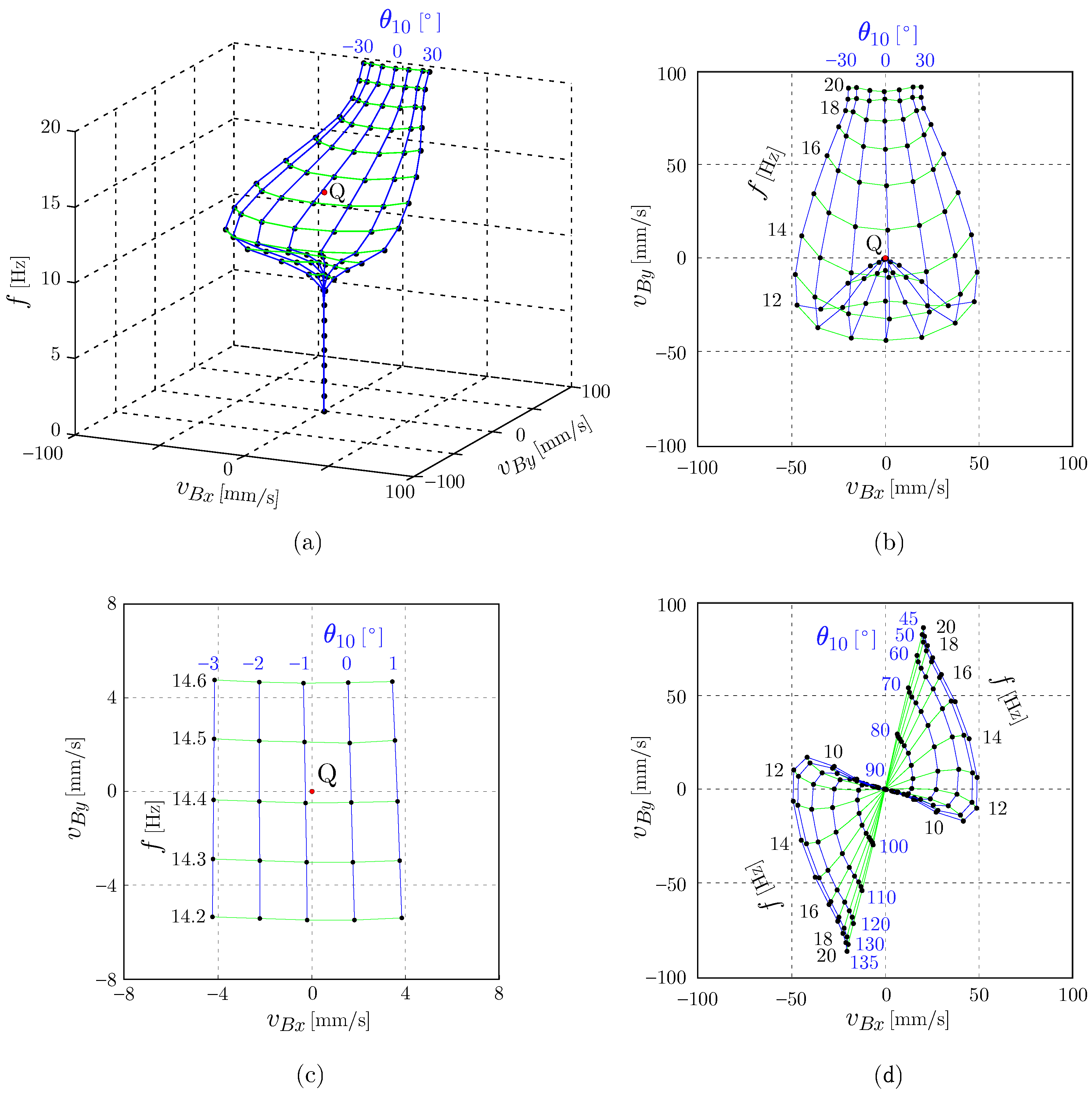
Figure 3a,b show the velocity maps, which indicate the relationship between frequency f, offset angle , and the induced velocity of the part , where Figure 3a,b correspond with a bird’s-eye view and a top view, respectively. If the frequency f is too small, such as Hz, the velocity of the part cannot be induced. This is because the inertia force applied to the part is less than the friction force. If the frequency Hz, the velocity begins to be induced toward the negative y direction and . If the frequency becomes larger and Hz, increases and becomes once at approximately Hz. Then, with frequency Hz, the induced velocity becomes . As mentioned above, the frequency f mainly changes the y directional component of the induced velocity, . In contrast, the offset angle mainly changes the x directional component of the induced velocity, . A positive or negative offset angle induces a positive or negative velocity component , respectively. An important point here is that the velocity region spanned by the two input parameters f and expands to every quadrant in Figure 3b. This means that the velocity of the part can be generated omnidirectionally. In addition, an interesting observation is that there exists a zero velocity point at which with an intermediate frequency, as indicated by point Q.
Figure 3c shows a detailed view in the neighborhood of point Q. Let denote the frequency and offset angle leading to point Q. In this case, are obtained. As shown in Figure 3c, an orthogonality is observed between the effects of the frequency f and offset angle on the velocity map. The velocity components and change linearly with respect to and f, respectively. Figure 4 explains such characteristics physically. Figure 4a shows the orbit of the plate by . When , the orbit of the plate is generated approximately in the y-z plane. With such an orbit, the x directional force is not applied to the part. Therefore, is achieved by . In addition, is achieved with a particular frequency and its orbit of the plate. In this case, the part actually moves and comes back to the original location after one cycle, including the y directional small sliding and/or jumping motions. The offset angle and frequency depend on the friction property between the part and the plate. The relationship between them is investigated in the next subsection. Figure 4b shows the case where f is changed while keeping . In this case, the shape of the orbit of the plate varies in the y-z plane with respect to f, and thus, is controlled. Figure 4c shows the case where is changed while keeping . In this case, the orbit is tilted without changing its shape with respect to , and thus, is controlled.
Note that the above characteristics are generated by the design of the manipulator introduced in this paper. In the preliminary version [23], the manipulator was designed so that the output link directs to the vertical direction in the initial state (). Owing to the mechanical restriction, its range of offset angles corresponded with . Figure 3d shows the velocity map for the manipulator in [23]. It can be confirmed that the induced velocity of the part cannot be produced omnidirectionally. The orbits in the y-z plane by , as shown in Figure 4b, never be generated and the manipulator could not induce a velocity vector along the y axis.
4.3. Influence of Friction Property
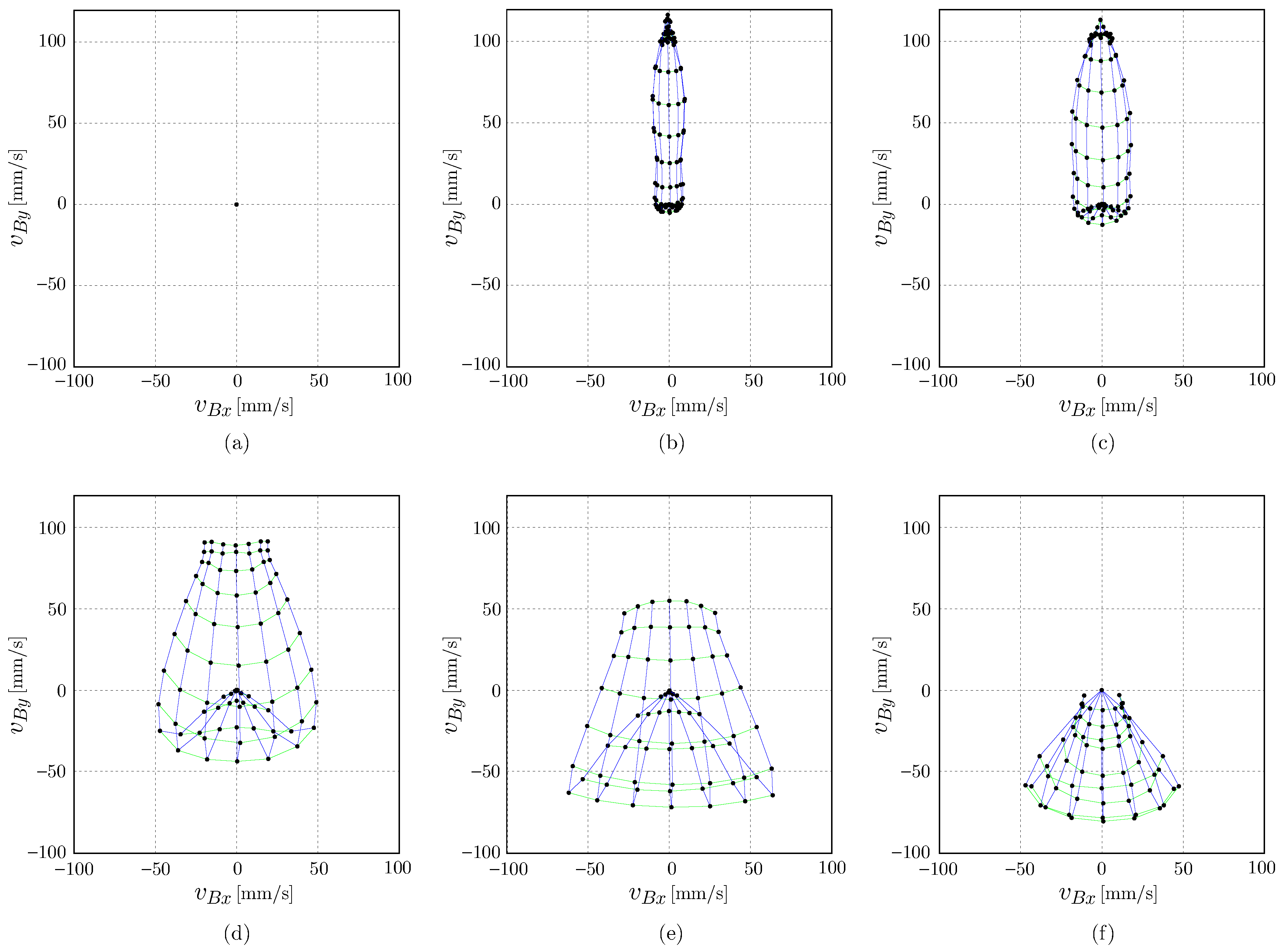
Figure 5 shows velocity maps of the part under various friction properties, where all parameters except for the friction coefficient are the same as those in the simulation described in Section 4.2. Figure 5a–f correspond to , respectively. As shown in Figure 5a, the velocity vector is always zero when no frictional force acts on the part. As shown in Figure 5b,c, the region spanned by the two input parameters f and is narrow for slippery surfaces. As shown in Figure 5d,e, the region becomes wide for the appropriate frictional surfaces. As shown in Figure 5f, the region becomes small for a nonslip surface. Thus, the velocity map varies depending on the friction property. The results imply that the friction property is an essential design parameter in producing the velocity of the part in every direction with sufficient magnitude under the given ranges of input parameters f and . Figure 6 shows the relationship between the friction property and . As explained previously, the offset angle is close to zero regardless of . Besides, the frequency increases monotonously in a wide range with respect to . This is because the moving distances by sliding and jumping are sensitive to the friction property.
5. Visual Feedback Control
Let us consider the target-trajectory tracking of the part based on the input parameters . In practical cases, the manipulator would include construction errors that lead to plate orbit errors, and they work as disturbance in the position or velocity control of the part. In addition, the contact condition between the part and the plate surface would not be uniform with respect to the location of the part. Such a nonuniformity works as the disturbance. To compensate for the disturbance, this section introduces a simple visual feedback controller for tracking a reference trajectory.
Suppose that the position of the part is recognized via a vision sensor. Let denote the reference position vector of the part with respect to time. As shown in Figure 3a, when the part is controlled based on the stationary state by , at least once the part must move to the negative y direction, even if the positive y directional motion is needed. To address this issue, the zero velocity point Q generated by can be utilized as the ready state for moving the part omnidirectionally. Based on the above discussion, the input parameters to the actuator are given as follows:
where the first and second terms in the right side correspond with the feedforward and feedback inputs, respectively. Based on the orthogonality where f and control and , respectively, around the zero velocity point Q, the feedback input is given as follows:
where
are the proportional gain matrix, integral gain matrix, derivative gain matrix, and deviation vector, respectively. In the PID controller, the integral term can work for compensating the steady-state deviation caused by the initial error of . This means that practical values of can be obtained by a preliminary experiment using Equations (4) and (5) with a tentative and constant for the zero velocity. Under this setting, in Equation (4) in the steady-state corresponds with the practical .
6. Experiments
This section shows experiments using a prototype for confirming the validity of the proposed method. See the supplementary downloadable movie file that shows the prototype robot and the experiments.
6.1. Experimental Setup
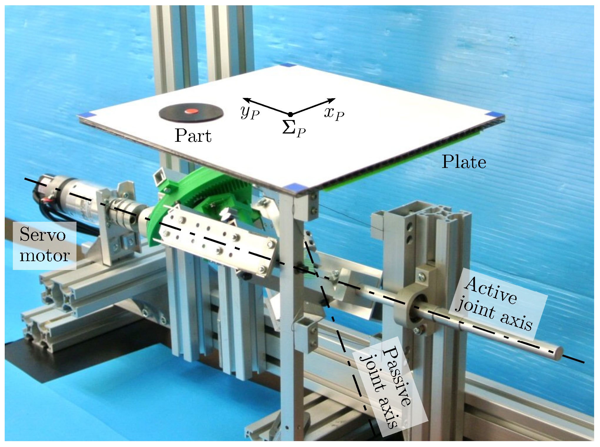
Figure 7 shows an overview of the prototype of the manipulator. The manipulator was designed and developed based on the model shown in Figure 2. An AC servo rotary motor (RSF-11B, Harmonic Drive Systems Inc.) controlled by a PC was installed to drive the active joint. An acrylic spring and an oil damper were attached as the viscoelastic element of the passive joint. Each joint was equipped with a rotary encoder to measure the angular displacement. The main parameters of the manipulator were as follows: mm, , Hz, , and . Here, and were experimentally identified by using the data of and under steady-state vibration. An acrylic square plate with a side of 200 mm was used as the end effector. A circular rubber sheet was used as the manipulated part. Its radius and thickness were 20 mm and 1 mm, respectively. The static and dynamic friction coefficients between the part and the plate surface were and , respectively. A marker was pasted on the part to enable visual detection of the position of the part. As vision sensor, a CMOS camera with pixel resolution and 30 fps was implemented at a height of 400 mm from the plate.
6.2. Experimental Results
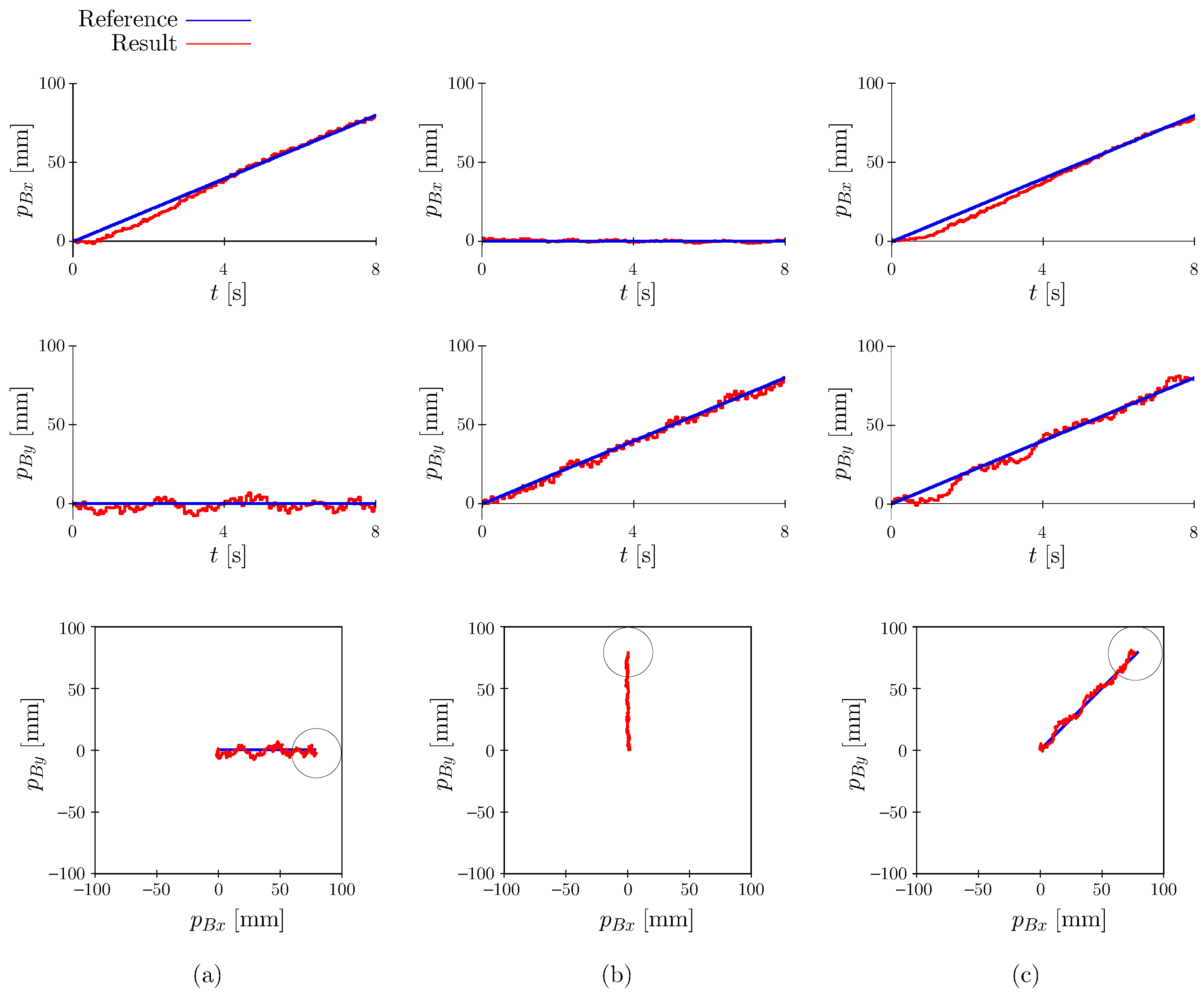
In the preliminary experiment, Hz and were obtained for the zero velocity point. By employing them, trajectory tracking tasks were examined using the visual feedback based on Equations (4) and (5). Figure 8 shows the representative experimental results where the reference trajectories of the part in Figure 8a, b, and c were given along the axis ( mm), axis ( mm), and diagonal ( mm), respectively, for s. In Figure 8, the position data of the part with respect to time , are shown, while its trajectory on the plate surface is drawn in the bottom. The PID gain was empirically given as , , , , , and . From the results, it can be confirmed that the proposed manipulator can control two-DoF motion of the part. Basically, a highly precise manipulation is not expected because the jumping and sliding of the part generated by the vibration of the plate are utilized. The mean values of the error mm were obtained as mm, mm, and mm for Figure 8a–c, respectively. The proposed method is suitable for rough positioning and transporting of the part.
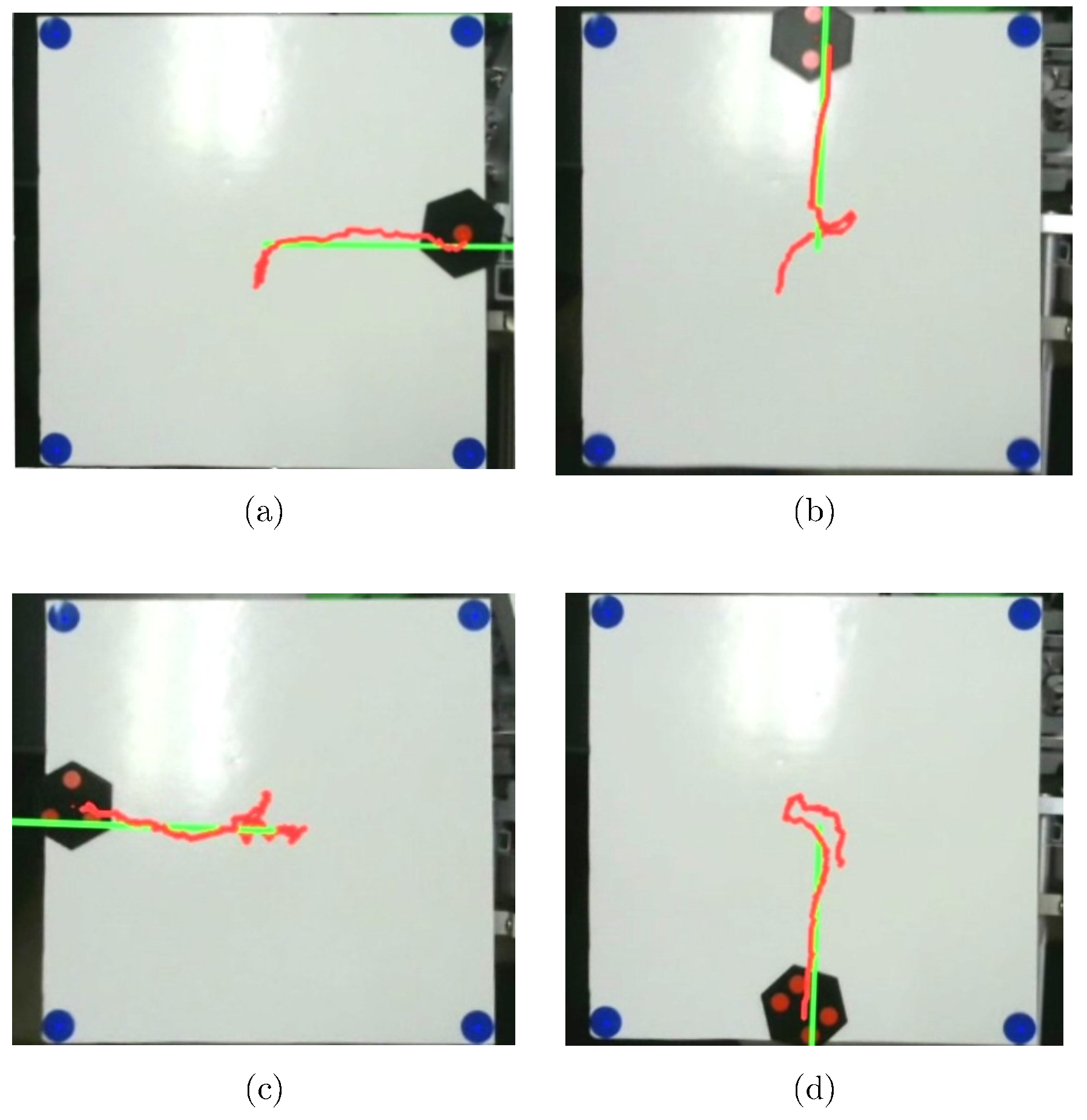
Figure 9 shows an application to a four-way part-feeding task. The outline of the part-feeding tasks is as follows. Four parts were prepared, to which one, two, three, and four circle marker(s) were pasted on, respectively. One of the parts was manually thrown to the surface of the plate. Based on the visual information obtained by the camera, the number of markers was recognized. After the part was moved to the center of the plate for the first 1 s, subsequently the parts with one, two, three, and four marker(s) were transported and fed into the right, upper, left, and lower direction, respectively. In Figure 9, the green and red lines indicate the reference and resultant trajectories, respectively. The above experiments show the feasibility of the proposed method that produces the omnidirectional manipulation by using one actuator.
7. Conclusions
This paper has presented a nonprehensile manipulation scheme wherein two-DoF translational motion of a part is controlled using only one actuator. The main results are summarized as follows:
- A manipulator with an underactuated mechanism with a viscoelastic element and a nonparallel axis layout was introduced. The vibrational orbit of a plate end effector varies based on the sinusoidal displacement input to an actuator.
- Via simulation analyses, the velocity map of a part was explored. It was revealed that the manipulator can produce an arbitrary velocity of the part omnidirectionally.
- In the neighborhood of a zero velocity point, there exists an orthogonality between the effects of the frequency and offset angle on the induced velocity. Based on the characteristics, a visual feedback control for manipulating the part was designed.
- The proposed approach was validated via experiments. The feasibility was confirmed and an application to a four-way part-feeding task was demonstrated.
Future works include an optimum problem to design the mechanical parameters, such as the viscoelasticity and angle between the two axes. By considering the relationship between the torque of the actuator, the viscoelasticity of the passive joint, and the induced velocity of the part, the energy efficiency of the system will be investigated.
Supplementary Materials
Supplementary Materials are available online at https://www.mdpi.com/2218-6581/7/3/34/s1.
Author Contributions
M.H. conceived of and designed the model. A.S. and K.Y. developed the system and performed the experiments. M.H. and A.S. analyzed the data and wrote the paper.
Acknowledgments
The authors would like to thank Hiroya Natsuhara with Mitsubishi Electric Corp. and Ryohei Sakashita with Mitsubishi Heavy Industries, Ltd. for their cooperation in the experimental works.
Conflicts of Interest
The authors declare no conflict of interest.
References
- Bicchi, A. Hands for Dexterous Manipulation and Robust Grasping: A Difficult Road Toward Simplicity. IEEE Trans. Rob. Autom. 2000, 16, 652–662. [Google Scholar] [CrossRef]
- Arai, H.; Khatib, O. Experiments with Dynamic Skills. In Proceedings of the 1994 Japan-USA Symposium on Flexible Automation : A Pacific Rim conference, Kobe, Japan, 11–18 July 1994; pp. 81–84. [Google Scholar]
- Amagai, A.; Takase, K. Implementation of Dynamic Manipulation with Visual Feedback and Its Application to Pick and Place Task. In Proceedings of the 2001 IEEE International Symposium on Assembly and Task Planning (ISATP2001), Fukuoka, Japan, 29–29 May 2001; pp. 344–350. [Google Scholar]
- Reznik, D.; Canny, J. A Flat Rigid Plate is a Universal Planar Manipulator. In Proceedings of the 1998 IEEE International Conference on Robotics and Automation, Leuven, Belgium, 20–20 May 1998; pp. 1471–1477. [Google Scholar]
- Reznik, D.; Canny, J. C’mon Part, Do the Local Motion! In Proceedings of the 2001 ICRA. IEEE International Conference on Robotics and Automation, Seoul, South Korea, 21–26 May 2001; pp. 2235–2242. [Google Scholar]
- Vose, T.H.; Umbanhowar, P.; Lynch, K.M. Vibration-Induced Frictional Force Fields on a Rigid Plate. In Proceedings of the 2007 IEEE International Conference on Robotics and Automation, Roma, Italy, 10–14 April 2007; pp. 660–667. [Google Scholar]
- Vose, T.H.; Umbanhowar, P.; Lynch, K.M. Friction-Induced Velocity Fields for Point Parts Sliding on a Rigid Oscillated Plate. Int. J. Rob. Res. 2009, 28, 1020–1039. [Google Scholar] [CrossRef] [Green Version]
- Vose, T.H.; Umbanhowar, P.; Lynch, K.M. Friction-Induced Lines of Attraction and Repulsion for Parts Sliding on a Oscillated Plate. IEEE Trans. Autom. Sci. Eng. 2009, 6, 685–699. [Google Scholar] [CrossRef]
- Vose, T.H.; Umbanhowar, P.; Lynch, K.M. Toward the Set of Frictional Velocity Fields Generable by 6-Degree-of-Freedom Oscillatory Motion of a Rigid Plate. In Proceedings of the 2010 IEEE International Conference on Robotics and Automation, Anchorage, AK, USA, 3–7 May 2010; pp. 540–547. [Google Scholar]
- Vose, T.H.; Umbanhowar, P.; Lynch, K.M. Sliding Manipulation of Rigid Bodies on a Controlled 6-DoF Plate. Int. J Rob. Res. 2012, 31, 819–838. [Google Scholar] [CrossRef]
- Mitani, A.; Sugano, N.; Hirai, S. Microparts Feeding by a Saw-Tooth Surface. IEEE/ASME Trans. Mechatron. 2006, 11, 671–681. [Google Scholar] [CrossRef]
- Mitani, A.; Hirai, S. Submillimeter Micropart Feeding Along an Asymmetric Femtosecond-Laser- Microfabricated Surface. Int. J. Autom. Technol. 2009, 3, 151–156. [Google Scholar] [CrossRef]
- Le, P.H.; Dinh, T.X.; Mitani, A.; Hirai, S. A Study on the Motion of Micro-Parts on a Saw-Tooth Surface by the PTV Method. J. Syst. Des. Dyn. 2012, 6, 73–80. [Google Scholar] [CrossRef] [Green Version]
- Le, P.H.; Dinh, T.X.; Mitani, A.; Hirai, S. Effect of Geometry Parameters of Saw-tooth Surface on the Feeding Velocity of Micro-parts. IEEJ Trans. Electr. Electron. Eng. 2013, 8, S102–S105. [Google Scholar] [CrossRef]
- Umbanhowar, P.; Vose, T.H.; Mitani, A.; Hirai, S.; Lynch, K.M. The Effect of Anisotropic Friction on Vibratory Velocity Fields. In Proceedings of the IEEE International Conference on Robotics and Automation, Saint Paul, MN, USA, 14–18 May 2012; pp. 2584–2591. [Google Scholar]
- Higashimori, M.; Utsumi, K.; Omoto, Y.; Kaneko, M. Dynamic Manipulation Inspired by the Handling of a Pizza Peel. IEEE Trans. Rob. 2009, 25, 829–838. [Google Scholar] [CrossRef]
- Ramirez-Alpizar, I.G.; Higashimori, M.; Kaneko, M.; Tsai, C.; Kao, I. Dynamic Nonprehensile Manipulation for Rotating a Thin Deformable Object: An Analogy to Bipedal Gaits. IEEE Trans. Rob. 2012, 28, 607–618. [Google Scholar] [CrossRef]
- Ramirez-Alpizar, I.G.; Higashimori, M.; Kaneko, M. Identification of a Thin Flexible Object with Bipedal Gaits. In Proceedings of the 8th IEEE International Conference on Automation Science and Engineering, Seoul, Korea, 20–24 August 2012; pp. 952–957. [Google Scholar]
- Lynch, K.; Mason, M.T. Dynamic Nonprehensile Manipulation: Controllability, Planning and Experiments. Int. J. Rob.Res. 1999, 18, 64–92. [Google Scholar] [CrossRef]
- Böhringer, K.F.; Bhatt, V.; Goldberg, K. Sensorless Manipulation Using Transverse Vibrations of a Plate. In Proceedings of the IEEE International Conference on Robotics and Automation, Nagoya, Japan, 21–27 May 1995; pp. 1989–1996. [Google Scholar]
- Böhringer, K.F.; Donald, B.R.; MadDonald, N.C. What Programmable Vector Fields Can (and Cannot) Do: Force Field Algorithms for MEMS and Vibratory Plate Parts Feeders. In Proceedings of the IEEE International Conference on Robotics and Automation, Minneapolis, MN, USA, 22–28 April 1996; pp. 822–930. [Google Scholar]
- Böhringer, K.F.; Donald, B.R.; Bhatt, V.; Goldberg, K. Algorithms for Sensorless Manipulation Using a Vibrating Surface. Algorithmica 2000, 26, 389–429. [Google Scholar] [CrossRef] [Green Version]
- Natsuhara, H.; Higashimori, M. Dynamic Nonprehensile Manipulation by Using Active-passive Hybrid Joint with Nonparallel Axes. In Proceedings of the IEEE International Conference on Robotics and Automation, Seattle, WA, USA, 26–30 May 2015; pp. 2502–2507. [Google Scholar]
- Sakashita, R.; Higashimori, M. 1-Actuator 3-DoF Parts Feeding Using Hybrid Joint Mechanism with Twisted Axis Layout. In Proceedings of the IEEE International Conference on Robotics and Automation, Singapore, 29 May–3 June 2017; pp. 2335–2342. [Google Scholar]
Figure 1.
Nonprehensile manipulation using plate vibration. Omnidirectional velocity of a part can be induced. (a) Typical approach: two-DoF manipulation by two actuators. (b) Proposed approach: two-DoF manipulation by underactuated mechanism with one actuator.
Figure 1.
Nonprehensile manipulation using plate vibration. Omnidirectional velocity of a part can be induced. (a) Typical approach: two-DoF manipulation by two actuators. (b) Proposed approach: two-DoF manipulation by underactuated mechanism with one actuator.
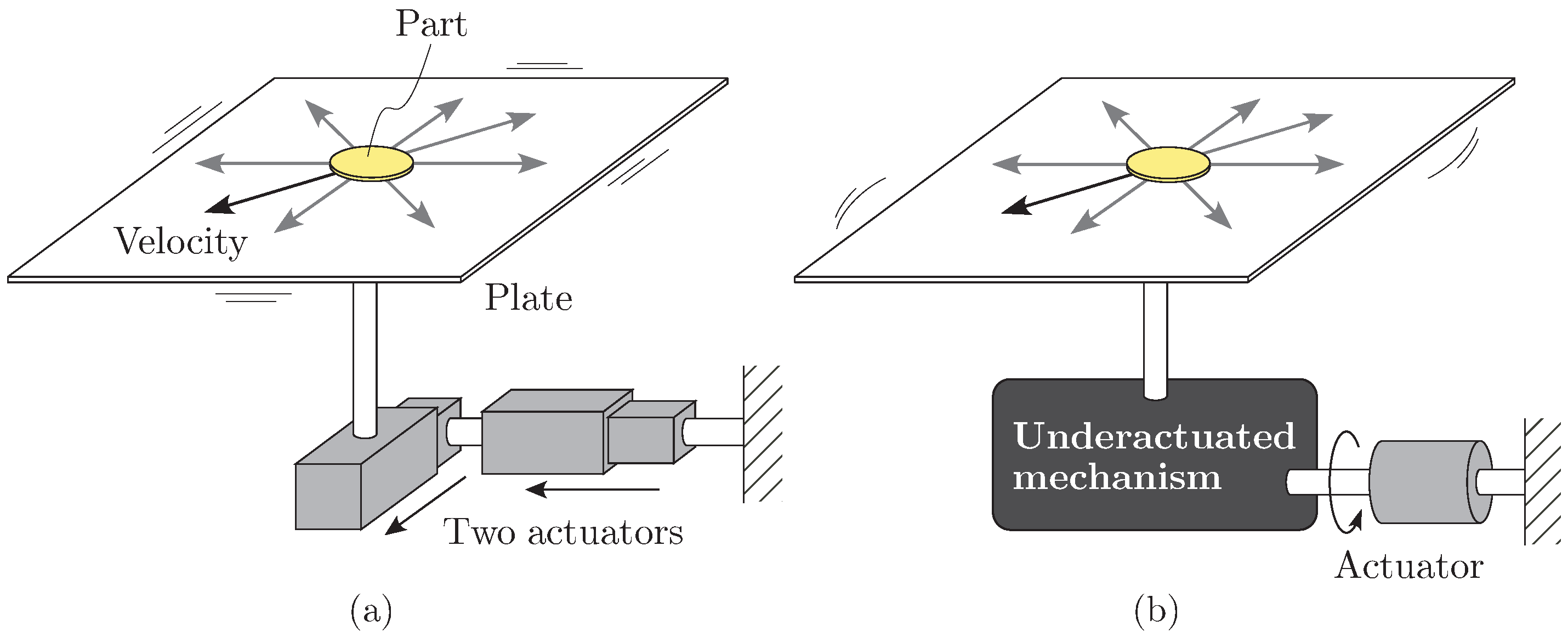
Figure 2.
Model of the proposed manipulator. (a) Owing to the underactuated joint mechanism, the orbit of the plate end effector varies based on the vibrational input to the actuator, while parallel linkage maintains the plate horizontal. A planner part located on the vibrating plate moves by sliding and jumping. (b) The tip of the output link draws an elliptic-like orbit by the combination of two sinusoidal joint motions and with the common frequency f. (c) The vibrational orbit varies with respect to the frequency f. (d) The orientation of the orbit varies with respect to the offset angle while keeping its shape and size.

Figure 3.
Velocity map indicating the relationship between the frequency f, offset angle , and induced velocity of the part . (a) Bird’s-eye view. (b) Top view. (c) Detailed view in the neighborhood of the zero velocity point Q. The velocity of the part can be induced omnidirectionally. Especially in the neighborhood of the point Q, there exits an orthogonality between the effects of the frequency f and offset angle . (d) Velocity map for the manipulator in [23]. The velocity of the part cannot be induced omnidirectionally.

Figure 4.
The induced velocity in the neighborhood of the zero velocity point. (a) The zero velocity is generated by . The orbit of the plate is generated approximately in the y-z plane. After one cycle including the y directional small sliding and/or jumping, the part comes back to the original location. (b) Under , the shape of the orbit of the plate varies in the y-z plane with respect to f, and thus is controlled. (c) Under , the orbit of the plate is tilted without changing its shape with respect to , and thus is controlled.
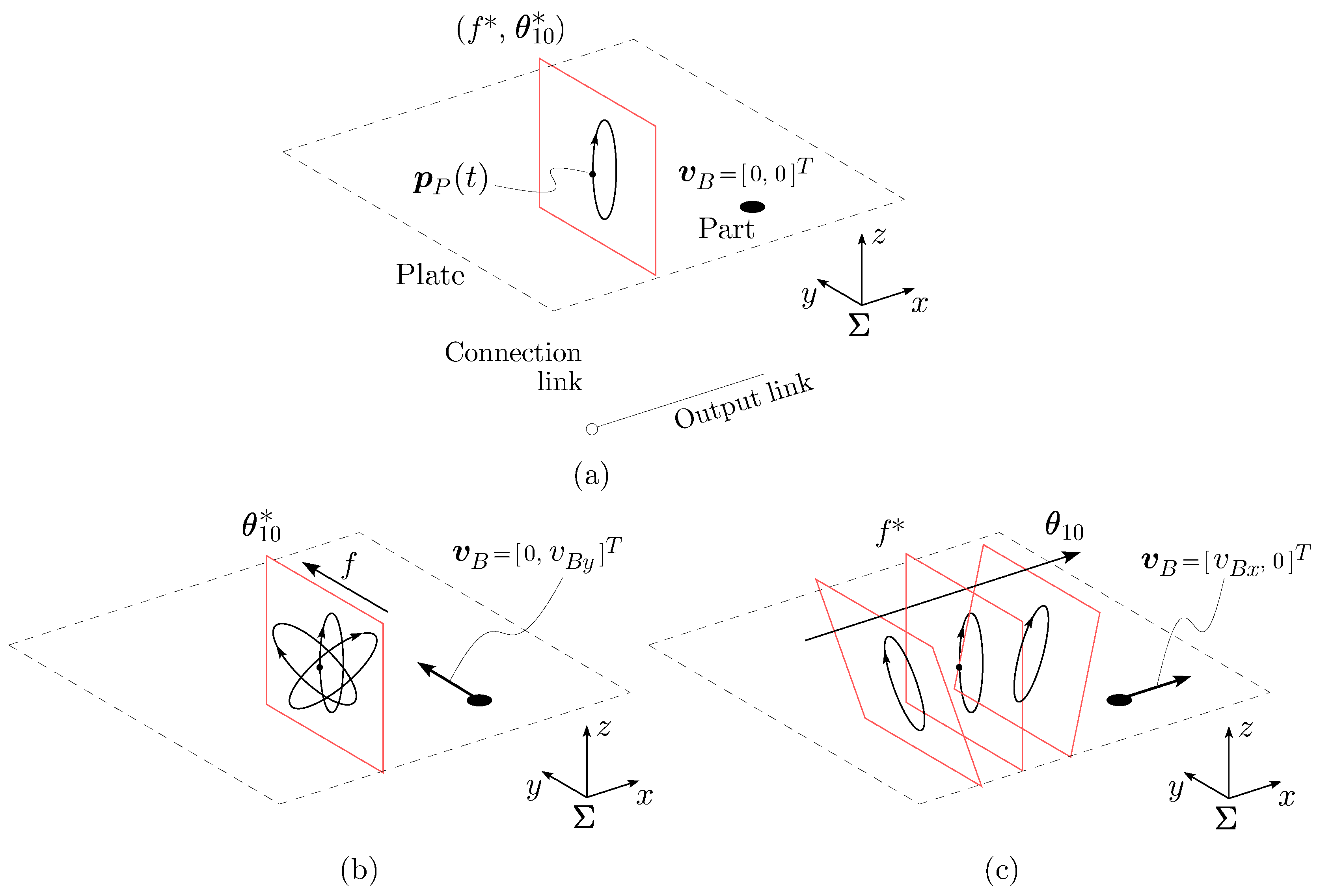
Figure 5.
Velocity maps for different friction properties. (a) . (b) . (c) . (d) . (e) . (f) . The region spanned by the two input parameters Hz and varies depending on the friction property.
Figure 5.
Velocity maps for different friction properties. (a) . (b) . (c) . (d) . (e) . (f) . The region spanned by the two input parameters Hz and varies depending on the friction property.

Figure 6.
The relationship between the friction coefficient and the input parameters leading the zero velocity point Q. (a) vs. . (b) vs. . The frequency is sensitive to the friction coefficient while the offset angle constantly.
Figure 6.
The relationship between the friction coefficient and the input parameters leading the zero velocity point Q. (a) vs. . (b) vs. . The frequency is sensitive to the friction coefficient while the offset angle constantly.
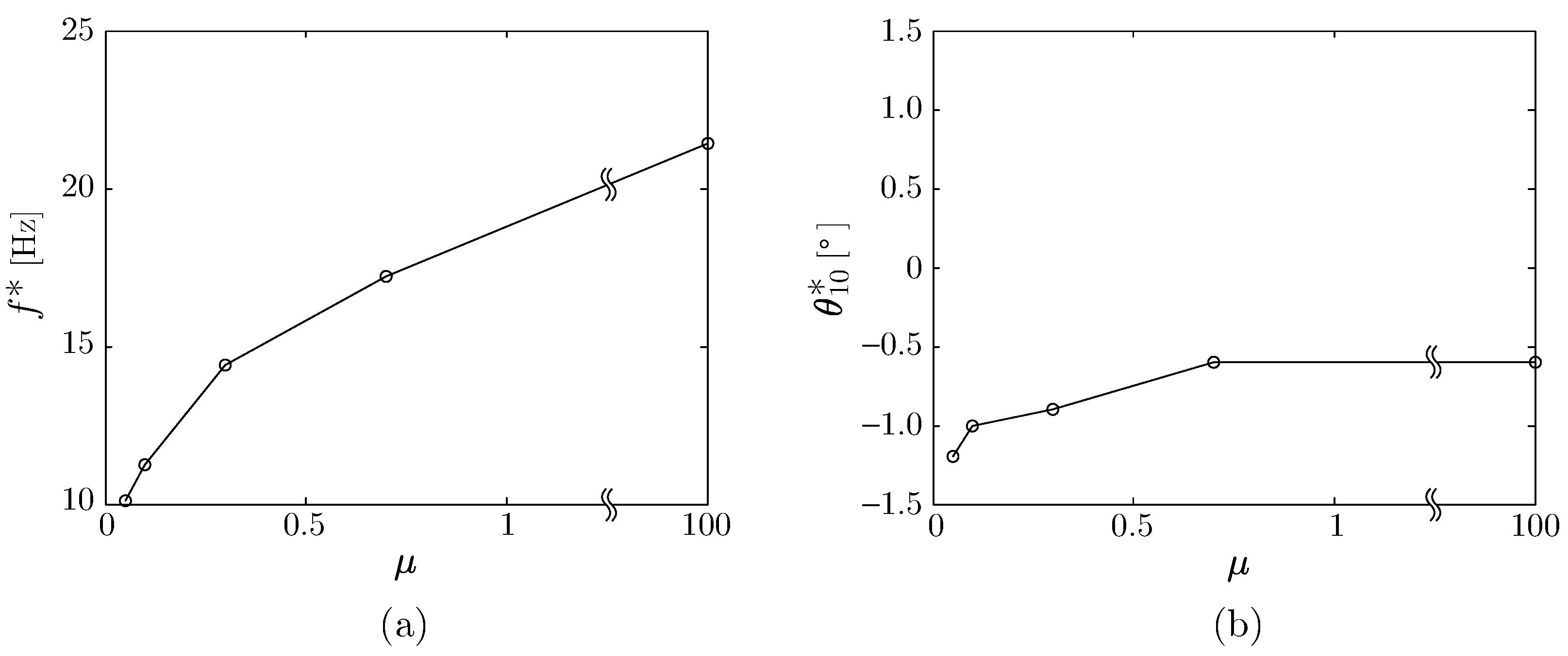
Figure 7.
Overview of the prototype manipulator.

Figure 8.
Experimental results in trajectory tracking tasks. (a) Trajectory along the axis ( mm) . (b) Trajectory along the axis ( mm). (c) Trajectory along a diagonal ( mm).
Figure 8.
Experimental results in trajectory tracking tasks. (a) Trajectory along the axis ( mm) . (b) Trajectory along the axis ( mm). (c) Trajectory along a diagonal ( mm).

Figure 9.
An application to a four-way part-feeding task. Parts with one, two, three, and four marker(s) were transported and fed into the right, upper, left, and lower direction, respectively.
Figure 9.
An application to a four-way part-feeding task. Parts with one, two, three, and four marker(s) were transported and fed into the right, upper, left, and lower direction, respectively.
© 2018 by the authors. Licensee MDPI, Basel, Switzerland. This article is an open access article distributed under the terms and conditions of the Creative Commons Attribution (CC BY) license (http://creativecommons.org/licenses/by/4.0/).
Share and Cite
MDPI and ACS Style
Higashimori, M.; Yamaguchi, K.; Shibata, A. Omnidirectional Nonprehensile Manipulation Using Only One Actuator. Robotics 2018, 7, 34. https://doi.org/10.3390/robotics7030034
AMA Style
Higashimori M, Yamaguchi K, Shibata A. Omnidirectional Nonprehensile Manipulation Using Only One Actuator. Robotics. 2018; 7(3):34. https://doi.org/10.3390/robotics7030034
Chicago/Turabian StyleHigashimori, Mitsuru, Kohei Yamaguchi, and Akihide Shibata. 2018. "Omnidirectional Nonprehensile Manipulation Using Only One Actuator" Robotics 7, no. 3: 34. https://doi.org/10.3390/robotics7030034
Note that from the first issue of 2016, this journal uses article numbers instead of page numbers. See further details here.