Automation of Electrical Cable Harnesses Testing
by
 ,
,
Zhuming Bi
1,*, 
Carlos Pomalaza-Ráez
2,
Dustin Hershberger
1,
Jeremy Dawson
1,
Andrew Lehman
1,
John Yurek
2 and
Jared Ball
2 1
Department of Civil and Mechanical Engineering, Purdue University Fort Wayne, Fort Wayne, IN 46805, USA
2
Department of Electrical and Computer Engineering, Purdue University Fort Wayne, Fort Wayne, IN 46805, USA
*
Author to whom correspondence should be addressed.
Robotics 2018, 7(1), 1; https://doi.org/10.3390/robotics7010001
Submission received: 26 October 2017
/
Revised: 13 December 2017
/
Accepted: 19 December 2017
/
Published: 21 December 2017
(This article belongs to the Special Issue Robust and Resilient Robots)
Abstract
:Traditional automated systems, such as industrial robots, are applied in well-structured environments, and many automated systems have a limited adaptability to deal with complexity and uncertainty; therefore, the applications of industrial robots in small- and medium-sized enterprises (SMEs) are very limited. The majority of manual operations in SMEs are too complicated for automation. The rapidly developed information technologies (IT) has brought new opportunities for the automation of manufacturing and assembly processes in the ill-structured environments. Note that an automation solution should be designed to meet the given requirements of the specified application, and it differs from one application to another. In this paper, we look into the feasibility of automated testing for electric cable harnesses, and our focus is on some of the generic strategies for the improvement of the adaptability of automation solutions. Especially, the concept of modularization is adopted in developing hardware and software to maximize system adaptability in testing a wide scope of products. A proposed system has been implemented, and the system performances have been evaluated by executing tests on actual products. The testing experiments have shown that the automated system outperformed manual operations greatly in terms of cost-saving, productivity and reliability. Due to the potential of increasing system adaptability and cost reduction, the presented work has its theoretical and practical significance for an extension for other automation solutions in SMEs.
1. Introduction
Automation is playing more and more important roles in modern manufacturing industries. In contrast to human operators, automated machines can work restlessly and reliably with a high productivity. Automation can be a cost-effective means for a manufacturing enterprise to sustain its competitiveness in the globalized business environment. Manufacturing technologies cannot be advanced without the wide applications of intelligent machines [1,2]. Manufacturing enterprises rely heavily on automation to achieve high quality and productivity, reduce cost, and deal with labor shortages [3,4]. Despite the numerous advantages of system automation, robotic systems in traditional applications lack flexibility in dealing with changes and uncertainties, and this turns out to be a significant challenge to use robots in small- and medium-sized enterprises (SMEs). The quantity of the same tasks is usually limited. If either robotic hardware or program have their limitations in coping with a variety of tasks, applying a robot might cause some issues, such as poor utilization rate, long setup time, and high initial investment, and, thus, a high unit cost of products [5]. To replace human operators with better performance, the automation solution should not only be affordable, but also be flexible to accommodate as many different tasks as possible. Therefore, we are motivated to address the aforementioned concerns by using modularized architecture in the automated solutions for enhanced system adaptability [6,7,8,9], while the selections and assemblies of modular components in a system can be varied and tailored to the needs in given applications [10]. It is also worth mentioning that due to the complexity and uncertainty, full automation is often cost-forbidding in production lines with small or limited batch volumes. Affordable automation solutions mostly require human and machine collaboration to synergize the advantages of human operators and machines [11,12,13]. In this paper, the semi-automated solution for harness testing is presented and used as the case study to illustrate the application of the modularization method.
In this paper, the solution to the testing automation of cable harnesses is used as the case study to illustrate the application of the modularization method. Testing operations at the client company are automated to replace human operators, shorten testing time, follow standardized tests, and achieve high consistency and quality. The rest of the paper is organized as follows: In Section 2, the features and variety of cable harnesses are introduced, the testing requirements of products are introduced, and the types of tested flaws and defects are classified. Some drawbacks of manual testing are discussed to identify some challenges of the automation solution for testing. In Section 3, the hardware of the mechanical and electronic sub-systems are presented. In Section 4, the control system and graphical user interface are discussed. In Section 5, the proposed method and system is implemented and prototyped, and the system performance is evaluated by performing tests on actual products. In Section 6, we summarize the presented work and our contribution for the development of modularized automated solutions. In addition, the plan for the extension of the proposed system is briefed.
2. Cable Harness and Testing Requirements
2.1. Cable Harness Products
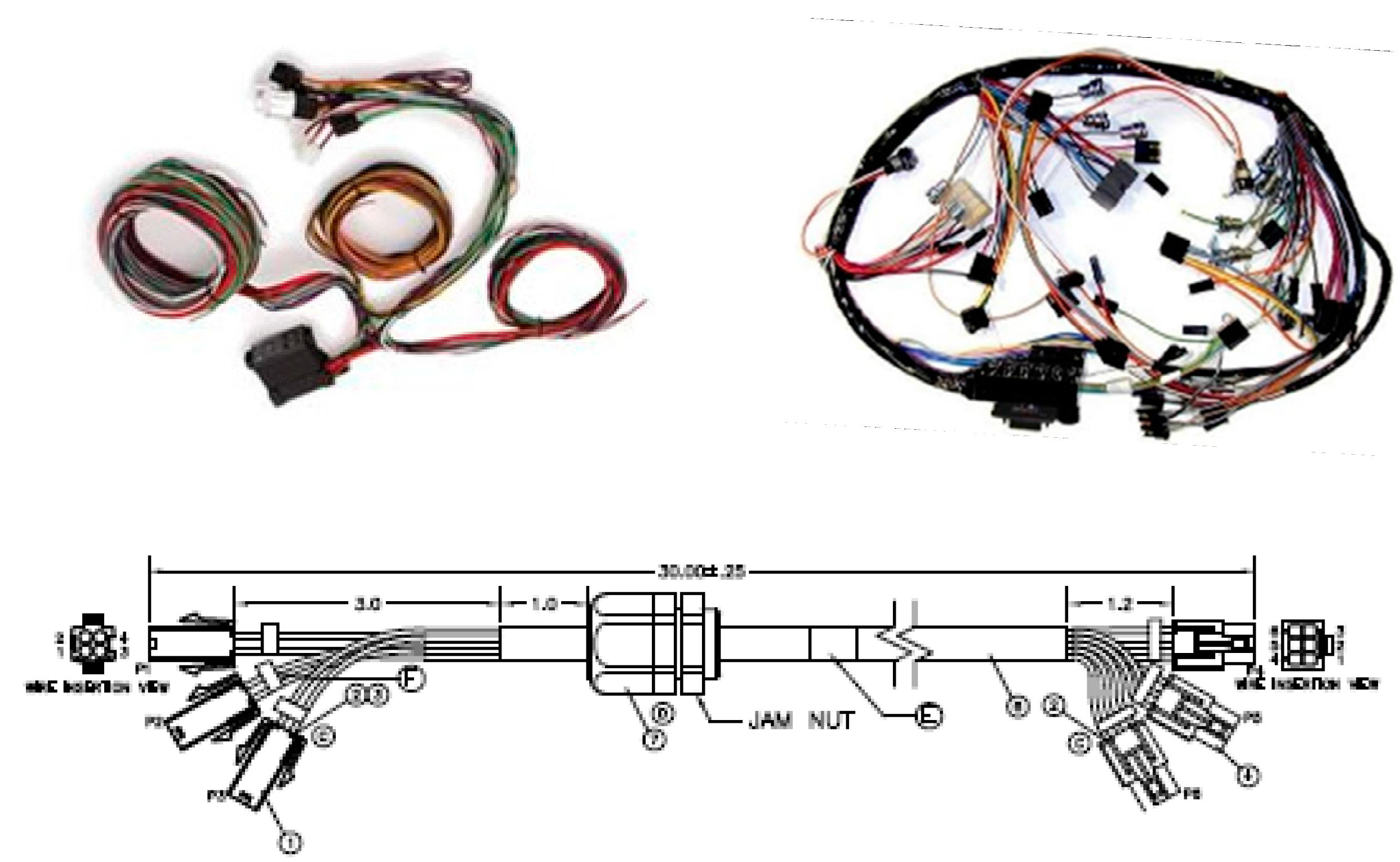
Figure 1 shows an example of a cable harness whose connections are required to be tested for quality assurance. Generally, a harness refers to a set of bonded wires which are used to transmit signals or electrical power in electric and electronic systems [14]. To meet the quality standards of products, harnesses must be tested accordingly. The testing methods and procedures for electronic systems have been extensively discussed in the literature [15]. However, it is worth noting that cable harnesses in modern electronics are becoming more and more complicated and diversified, and this brings challenges in cost-effectively testing various cable harnesses in production. As a matter of fact, the majority of SMEs in the field rely on human testers. Figure 2 shows an example where cable harnesses are tested by human operators. Some drawbacks of manual testing include long testing time, risk concerns to operators, subjective criteria for pass/fail tests, and testing variants by different operators.
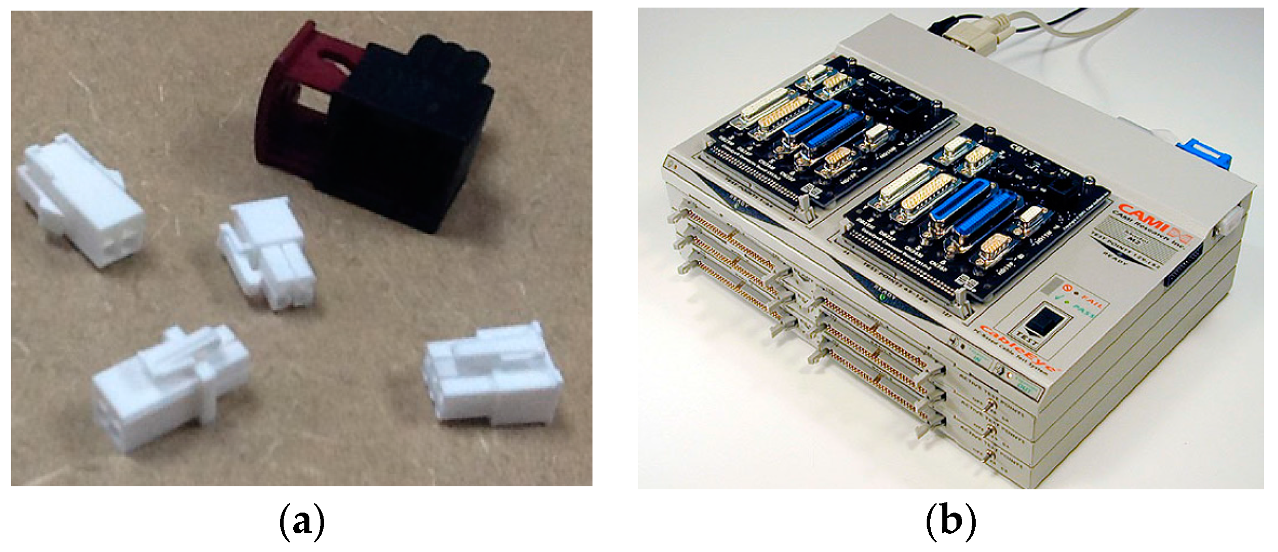
The most important concern for the automation of the testing process is to provide the flexibility for different types of cable harnesses by one testing system since a SME usually has a number of harnesses to be tested. One cable harness may differ from another in terms of the configuration of wires or the connection interface. Figure 3a shows that the plugs of the connections can vary from one harness to another. Note that most of the cable testers on the market, such as the one shown in Figure 3b, are dedicated devices, which can only be used to test harnesses with the same type of plugs. Therefore, the system adaptability for a variety of products must be considered as the primary requirement of a new testing system.
The common quality issues are mainly the loose connection of a cable harness to backplanes and printed circuit boards (PCB). For a comprehensive testing, the continuity, resistance, insulation resistance, dielectric breakdown, missed wires, and other intermittent defects must be diagnosed to determine if the cable harness passes or fails [16,17]. In addition, the system must be flexible to accommodate the testing needs for a variety of harness products in the client company.
2.2. Requirements of Harness Testing
Previously, due to a relatively low volume of each cable harness type, these harnesses were manually tested by human operators. The company found that manual testing took an extremely long time; moreover, the testing quality depended heavily on the visual inspection and subjective judgment. To address the aforementioned issues, the company expected to automate the testing process with affordable hardware and software components, so that cable harnesses can be tested efficiently and cost-effectively.
A new system is proposed to test the continuity of cable harness and alert operators if any irregularity is detected automatically. Other than the detection of discontinuity, dielectric breakdown, missed wires, and intermittent defects, the testing system should be designed to minimize the wear on harnesses and connectors, and the system must compete with testing all of the harness variants produced by the company. Therefore, the main functional requirements for the testing system include:
- ▪
- Detection of all types of defects: Some defects in harnesses, such as broken wires, mixed, cross-over or loose connections, will cause malfunctions in its application. The primary goal of cable testing is to identify these imperfect harness products.
- ▪
- Shortened cycle time: One main drawback of manual testing is the long testing time, which usually takes several minutes to test one cable harness. The automated testing system is expected to have a cycle time of testing less than 20 s, so that harnesses under test can be turned over within the demanded cycle time to catch up with the throughput of the current production line.
- ▪
- Setup time for tooling changeover of different products: The testing system is designed to test different harness types, and the products to be tested should be changed from time to time. Both of the settings for hardware and software are subjected to be adjusted for new products. The setup time for the tooling changeover must be less than 5 min.
- ▪
- Adaptability for product variants: The company has more than 20 conductors, which are produced on the same production line simultaneously. Therefore, the testing system should be flexible to test more than 20 harness types. In addition, the architectures of both software and hardware systems much be adaptable for the testing of new products in the future.
3. Modularization
To make a system adaptable, two primary methods are (1) to introduce flexible components which can be adjusted and controlled for different tasks and, (2) to adopt a modularized architecture where the system consists of different modules, and different types and number of modules can be selected and assembled in different ways for different tasks [7,8,9]. In this paper, we use the second approach to improve the system adaptability. The system architecture is modularized so that the functionalities of modular components can be decoupled to maximize the design spaces of these sub-components; the designs of individual modules can be revised and upgraded with less impact on other modules [3]. At the highest level of modular system architecture, functional modules in the testing system are classified into two distinct subsystems, i.e., the electrical sub-system and the mechanical sub-system.
The functional requirements of the electrical subsystem are (1) to test the continuity and insulation and, (2) to detect and classify the defects of harnesses. In addition, any type of motions in the testing system must be controlled adequately to meet the requirements of the product cycle time. Axiomatic design theory is applied to establish the mapping between functional requirements and designed components [6]. Therefore, the corresponding hardware of the electrical elements are presented as follows:
Electrical components consist of:
- ▪
- Control module: The control module is designed to meet the control requirement of testing machine. Other criteria of selecting a control module are (1) the ease of operation, and (2) the compatibility with other system modules. In addition, the programming platform must be determined since the testing system needs a program for users to set up the hardware configuration, perform testing, and generate testing reports.
- ▪
- Automated testing module: The testing system is applicable to a variety of cable harnesses. The interface of the testing module with the tested cable harness is configurable so that different connections can be mated to the testing system to perform the tests by the specified program automatically.
- ▪
- Power supply module: This module is responsible to provide power for all of the actuated mechanical components, as well as the electronic components with external power. Therefore, the selections of the power supplies depend on the designs of the control system and the testing module.
The mechanical system is required to possess the following functionalities: (1) the mechanical structure will house all of the electrically- and mechanically-actuated components in the testing system; (2) the mechanical interface will provide the flexibility to connect a variety of plugs of the tested harnesses; and (3) the safety assurance will prevent any potential risk of the manual intervenes duration the course of testing. Therefore, the main functional requirements of a mechanical system include the following:
- ▪
- Requirement for enclosure: This will be integrated with the control system so that the hardware interface to a cable harness can be automatically adjusted for the specified harness subject to testing.
- ▪
- Requirement for actuation: This is for the moving mechanism, via which the interface can be self-reconfigured to provide the connections for the testing of different harnesses.
- ▪
- Requirement for interface: This is for the interface to make the physical connection to a cable harness to be tested; it is adjustable so that all wires of the harness can be connected appropriately based on the information of its configuration.
Following the axiomatic design theory, the independence of functional requirements and design variables are considered, and this led to the need to develop five functional modules. Figure 4 shows these modules: supports for individual pins, configuration of pins, actuation of the pin array, securement of pins, and the testing controller. Hardware components needed to be designed or selected for these functional modules accordingly.
4. Implementation of the Proposed Testing System
Figure 5 illustrates the main components of the conceptual testing system. The proposed system was prototyped and implemented to evaluate its testing performances. To reduce the cost, the frame of the mechanical system used the off-the-shelf extruded aluminum products; only the moving parts in the mechanical system are machined, and again, the materials for these machined parts are common industrial materials, such as aluminum, steel, and stainless steel. To simplify the graphical user interface (GUI), a CTC touch screen is selected for the operator to run and terminate the testing system with one-touch control for starting or stopping.
4.1. Mechanical System Structure
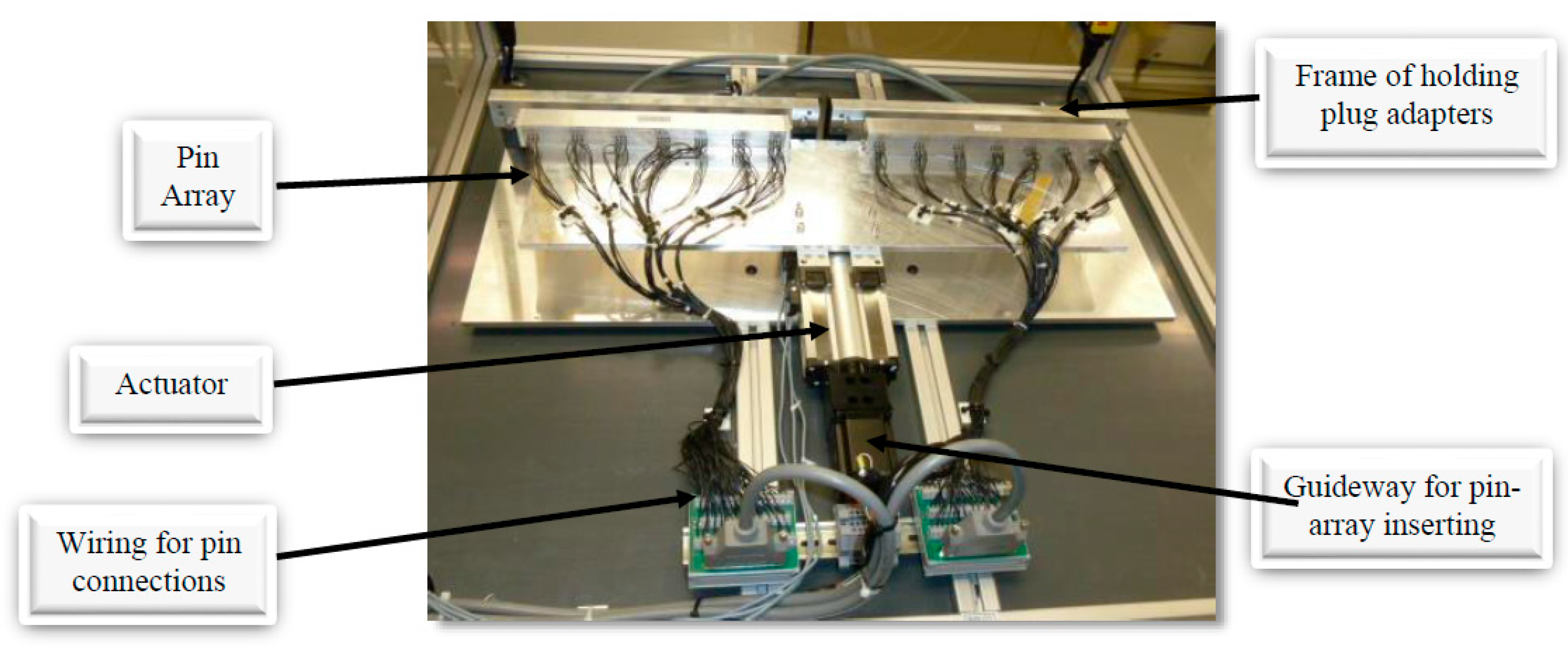
The actuated moving mechanism is implemented as an integrated assembly, which is driven by a linear actuator. All of static parts are fastened to the frame by T-nuts and bolts, and the main components of the moving mechanism are illustrated in Figure 6. A number of positions are available for an operator to mount the plugs of cable harnesses in place; the geometries at these positions are varied to accommodate different plug types of cable harnesses. The illustrated pins are loaded by springs and they are aligned specially with the terminals in the plugs.
4.2. Pins Loaded by Springs
Taking into consideration all variations of cable harnesses by the company, the maximized stroke length for the pin adjustment is less than 12.192-mm. Therefore, the stroke length for an adjustable spring is set as 12.192-mm. In addition, less mechanical force will be involved in connecting a cable harness to the terminal, therefore, the spring force is not critical, and the pitch diameter of a spring can be minimized for a 2.286-mm square hole for the smallest plug. As shown in Figure 7, the pin is designed to incorporate a relatively large length-to-diameter ratio; the pin has a pitch diameter of 1.27-mm at the end for the connection and 36.83-mm in length. Finally, with the criteria of strength, electrical conductivity, corrosion resistance, durability, and fatigue life, stainless steel is selected as the material for the pins.
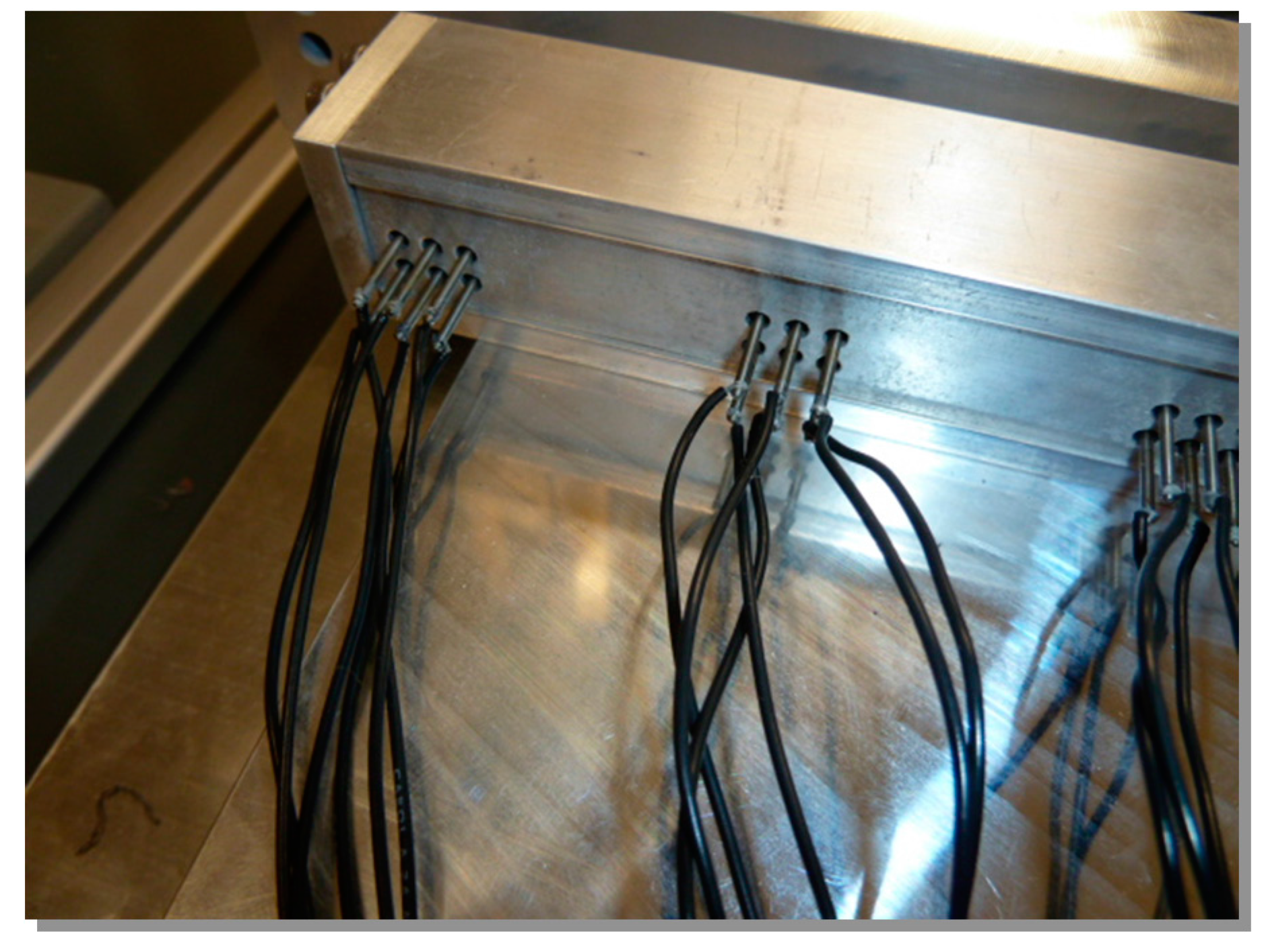
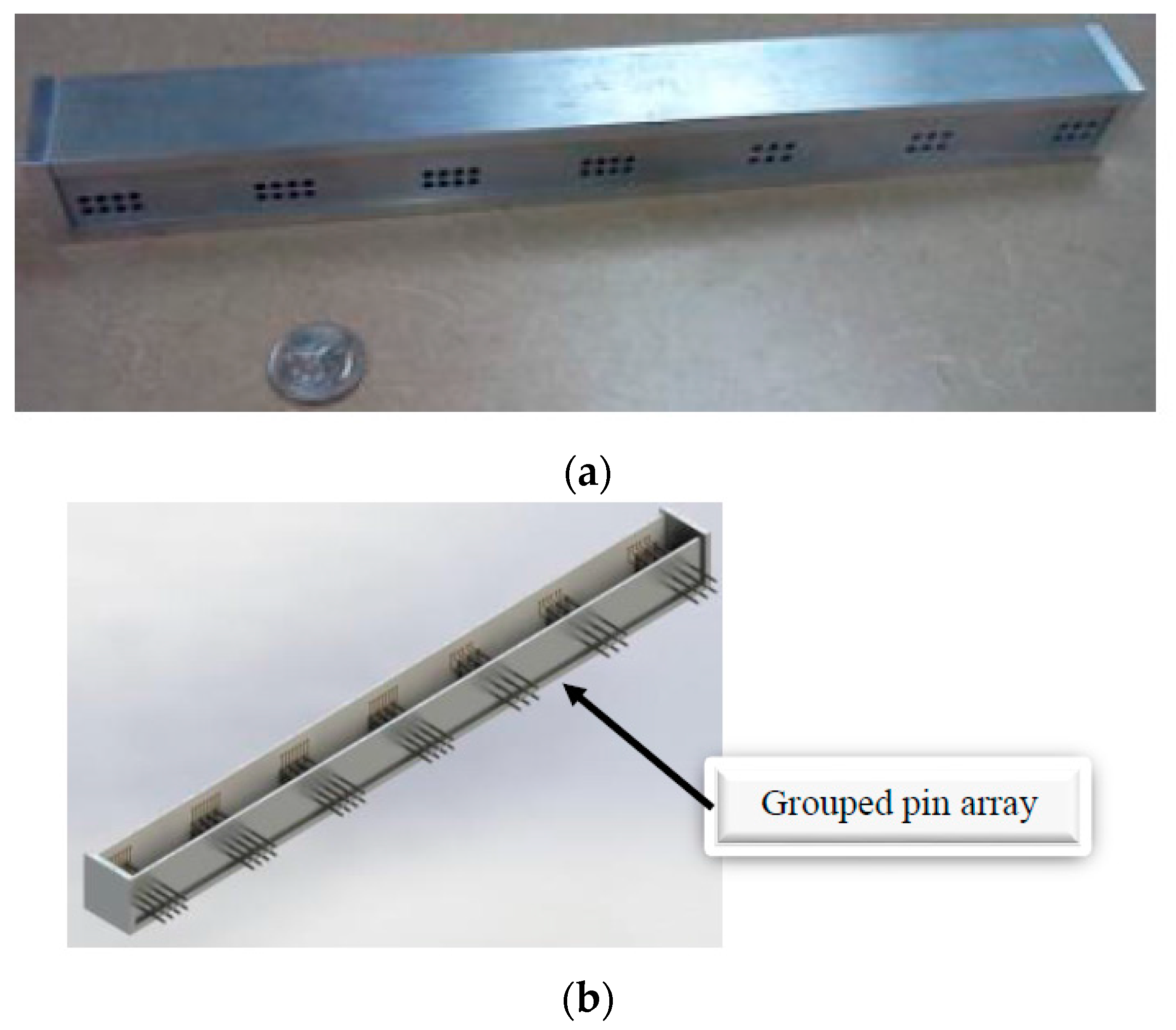
4.3. Configuration of the Pin Array
To align the pins with plugs in testing operation, pins are restrained by springs and placed in a rectangular container, which is illustrated in Figure 8. An array of holes are drilled on the lateral walls of the containers, while allowing the pins to pass over the walls. The patterned holes function to separate pins with the desired spacing, and they also guide the shafts to achieve the required points of contact with plugs. To increase the flexibility, the pin array is modularized. It consists of a number of the pin grid with 4 × 2 pins, the spacing is selected as 4.166-mm, which is compatible with all of the products at the company. All of the plugs to be tested have two rows of pins. Note that the hardware interface is modularized, i.e., the design change occurring to the pin array would not affect the designs of other components in the system. To adapt to the testing of possible products in future, alternative pin grids have been designed with a spacing of 50.80-mm.
4.4. Connection of Plugs
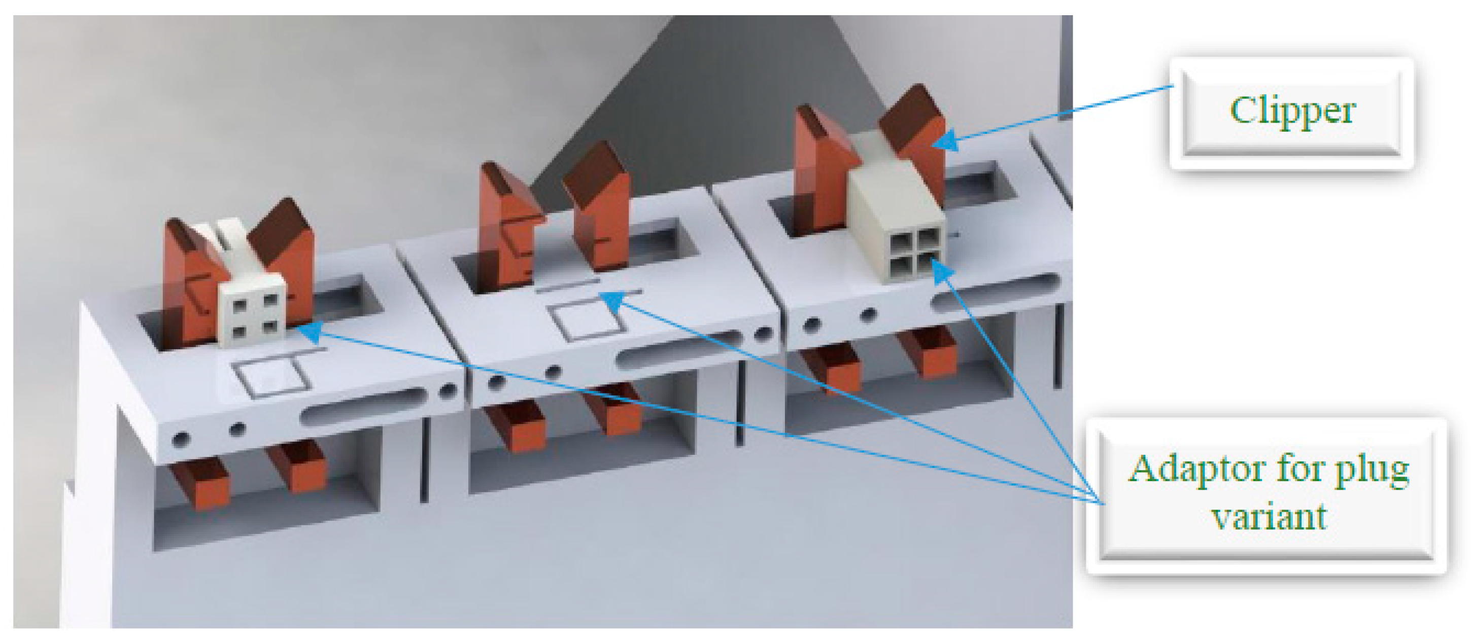
Figure 9 illustrates the connection of plugs, which is used to set up harnesses before the testing is performed. Two design requirements for the connection of plugs are to (1) minimize the damage to plugs and, (2) maximize the testing flexibility with an ease operation. In Figure 9, the arms for clamping are rounded so that plugs can make smooth contact with the pins; this reduces the possibility of an incidence for a scratch to plugs. The top of a clamping arm is angled at 45° so that the plug can be forced and secured at the desired position for testing. This allows an easy set-up for harness tests in a short time. The assembly included four modules of the clamping mechanism, a set of two clamping modules at the left side and right side, respectively. A slight difference exists between the clamping modules. The modules on the right can only be moved horizontally; this allows the adaptability for varying lengths of plugs subjected to tests. A fastening position of a clamping module is flexible for the adjustment. If the same type of harnesses is tested, the module can be fastened at its initial position for a batch of harnesses repeatedly with no adjustment. The other type of clamping modules (on the left) are mounted at a fixed position, but allow a free rotation; this allows the flexibility that a plug can be inserted into the center of two clamping arms.
4.5. Holders of Plugs
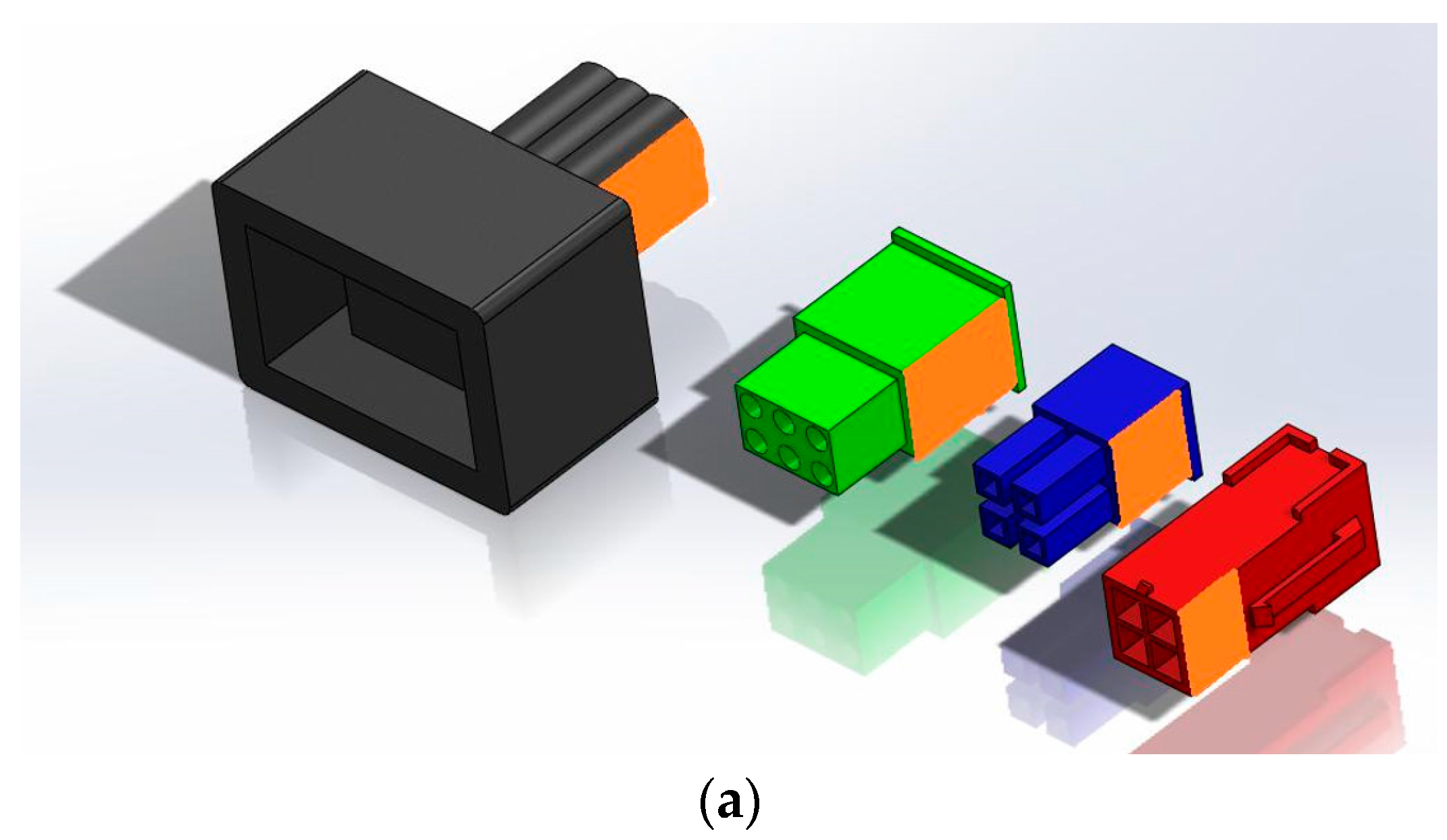
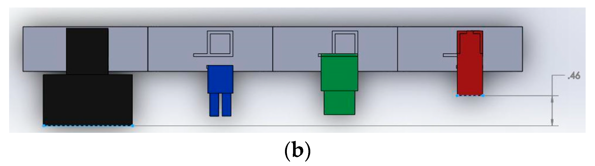
No interference is allowed when a plug is placed at the interface of the connection. The geometries of the plug holders must be customized and tailored to the cross-sectional profiles of the plugs. Figure 10 shows four examples of plug holders whose geometries are designed for the corresponding harnesses; each plug is uniquely flush on its surface for the specified plug. Along the wire direction, the plug length is also different which causes the different position of contacting surface. The adjustment is made by the springs attached on pins. The travel distance of a spring-loaded pin is set as 11.684-mm. To facilitate the machining process, the margin of space 0.508-mm has been added to compensate the stack-up tolerance. Therefore, the maximized travel of a spring-loaded pin is 12.192-mm.
4.6. Control System
The control system is required to (1) activate motion mechanism and, (2) perform testing processes. For the hardware of control system, The Allen Bradley CompactLogix system, (i.e., RSLogix5000 from Rockwall Automation, Milwaukee, WI, USA) was used; the base of such a logic system is 1769-L35E CPU. The communication of the RSLogix5000 is implemented using one RS232 and one Ethernet/IP port. In particular, RS232 ports are used to develop the graphical user interface (GUI) for testers, and the Ethernet ports are used data transmission and exchange in programming. The system also needs the power source for input and output modules. A 1769-PA4 power supply is used. Such a power supply can support up to eight modules, with four modules on each side. The same power supply is shared by all functional modules. To communicate with other sensing devices, a 1769-SDN DeviceNet network module is selected; this network module connects the simple industrial device (i.e., sensors and actuators) to high-level programming and control.
The CompactLogix system is equipped with a 24V-DC power supply, two 16-input 1769-IQ16, and two 16-output 1769-OB16 modules. To eliminate the impact of power consumption by the control system on testing result, an additional external power supply is used only for testing purpose, the selected power supply is Weimueller DC power supply with 10 amp to generate 24 V output signal. As a control system, it is capable of generating a testing signal at one end of harness, and probing the transmitted signal at the other end of the harness. The functional integrity of harnesses can be tested based on the detecting results from the system. The user needs a software interface to access the system. The graphical user interface has been implemented on a personal computer (PC)-based human machine interface (HMI) touch panel. As shown in Figure 11, the user can specify the part number for the harness to be tested, run a test, and stop a test at any time. The interface also includes an emergency stop button and system enable mounted on an enclosure. Figure 12 gives the schematic of the circuit for the implementation of the graphical user interface.
4.7. Control Program for Testing
The control system for testing has been implemented and operated on the Allen Bradley programmable logical controller (PLC) in the ladder logic format. The execution of code follows the sequence from left to right on each rung and from top to bottom from rung to rung. Statements in each rung can be for setting or revising the value of parameters, read input, or send output. Generally, a PLC platform also support some complex operations such as counting, computing, conditioning, and looping. For the testing purpose, the required functions of the PLC are shifting register values, obtaining inputs and generating outputs at a specified time and sequence. In addition, the testing system was incorporated with a number of new safety features to minimize the potential risks to operators. For example, acrylic panels were placed to prevent unintended intrusions from the sides of the testing platform. At the front door where harnesses are loaded and unloaded, a light curtain is placed so that the testing process can be automatically terminated when an intrusion is detected. This eliminates the possibility of injuries if an operator makes physical contact with any electric circuit from some moving parts in the system. The connected emergency button will shut down the power supply immediately when an abnormal condition is detected.
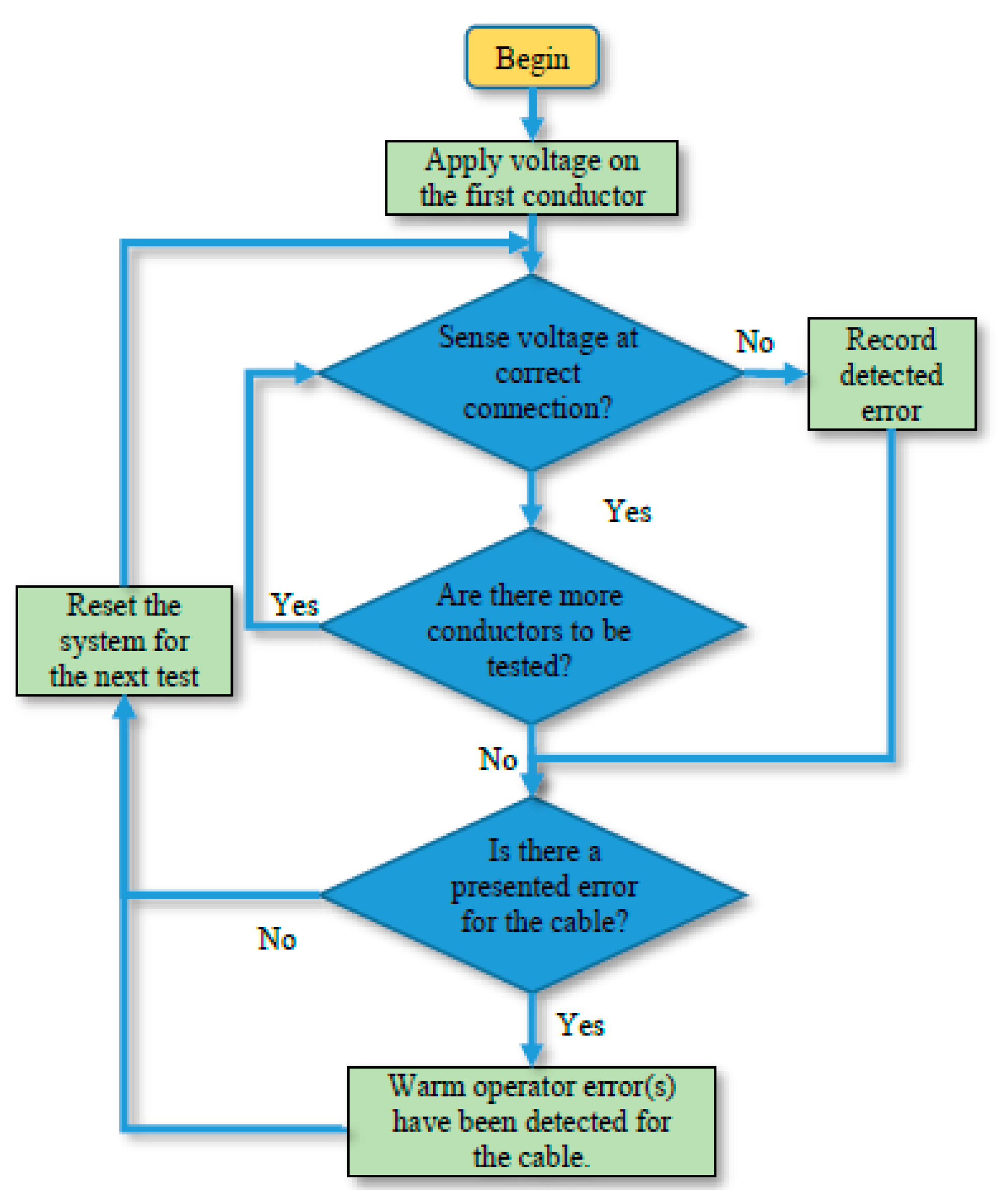
Figure 13 gives the flowchart of the program for harness testing. After the cable harness has been mounted and connected appropriately, the program is initialized by an operator with the Run button. A DC signal with 24 V is generated at the end of the firstly designated conductor from the input side of harness, and the output conductors of the harness are scanned progressively to determine the connected conductor with the 24 V potential. Once a conductor with a 24 V potential is identified, its identity is recorded and stored until the testing of the harness is completed; this process will be repeated until all of input conductors have been tested, respectively.
After the testing has been completed for a harness, the monitor screen will display a summary of the testing results for the harness. The testing result of a harness can be ‘pass’ and ‘no-pass’. The conclusion of ‘pass’ indicates that all of wires in the tested harness are connected and functioned adequately as designed. The conclusion of ‘no-pass’ indicates the detected malfunction(s) of the tested harness; it alerts the operator with the red background on the screen. If the type of malfunction has to be further classified, the operator can look into the data collected by the controller during testing to identify the problematic wire(s). Additional diagnosis steps are optional for testing of harness batches. The System Enable button is used to reset the system so that the collected data for previous tested can be cleared and transferred to the permanent storage, and the system be made ready for testing of the next harness. The System Enable button also ensures that an operator learns the testing result of the current harness before he/she tests the next one.
5. System Prototyping and Experiments
To evaluate the effectiveness of the proposed design concept, the testing system was developed and experiments were conducted to evaluate the system performance. Unit tests were performed on individual modules and proven that all of them met the required functionalities. At the system level, a number of harness products were randomly selected by the company and those harnesses were tested manually and by the developed system. Among the selected harnesses, malfunctioned harnesses with crossed and open connections were included, and all of them were detected successfully by the proposed system noting that those harnesses had no visible damage from their appearances.
The collected statistics from the experiment was summarized in Table 1. It shows that all of the quantified design objectives were achieved in the experiments. More specifically, harness testing can be performed semi-automatically with reliable outcomes and at a higher productivity. The average times for each operation by the tester were recorded as follows:
- ▪
- Set up a harnesses to be tested: 11.8 s;
- ▪
- Run a test: 4.2 s from beginning to end;
- ▪
- Remove a harness from the platform: <4 s;
- ▪
- Reconfigure testing setup: <2 min;
- ▪
- The shortest testing time: <18 s;
- ▪
- Train a new operator: <2 min.
6. Summary and Conclusions
We argue that one significant bottleneck in promoting robotic applications with a wider scope is how to develop automated systems for small and medium sized enterprises (SMEs) cost-effectively. The promising strategy to address this concern is to modularize a solution system so that the automated system can be reconfigured from time to time to adapt the changeable needs in the system application. Each system configuration can be optimized to meet the specific needs of the application in the given timeframe. The concept of modularization has been elaborated and its application has been illustrated via a case study.
The modularization concept has been applied to automate the testing processes of cable harnesses for a SME. The aim of modularization is to decouple the complexity of mechanical, electrical and electronic, and control components. The system adaptability has also been enhanced since the designs of individual modules can be changed to meet new testing needs without an impact on other system components. The proposed system has been developed, and the comparable study of manual and automated testing has been conducted. It has shown that the designed system has outperformed manual tests in terms of productivity, reliability, safety, and cost-effectiveness. The design concept of customization and modularization can be extended for the development of other automated solutions for SMEs.
One of the important future works is how to make the whole system with a high degree of resilience [18,19,20]. The resilience for such a system is very important, as those cables are susceptive to broken, and as such the requirement in-situ to the automated robotic system may be beyond its original requirement. This situation may happen unexpectedly. How to design the automatic robotic system such that it can change itself to meet the change in the requirements is an interesting question to be further studied.
Acknowledgments
The author Zhuming Bi would like to acknowledge the support by the State International Science and Technology Cooperation Special Items (Grant No. 2015DFA11700), the Frontier and Key Technology Innovation Special Funds of Guangdong Province (Grant No. 2014B090919002, 2015B010917003), and the Program of Foshan Innovation Team of Science and Technology (Grant No. 2015IT100072).
Author Contributions
Z.B. and C. P.-R. conceived the research framework and defined the project; D.H., J.D., and A.L. implemented the design and testing of mechanical sub-system; J.Y and J.B. implemented the design and testing of electrical and control sub-systems; Z.B. and C. P.-R. prepared and revised the manuscript.
Conflicts of Interest
The authors declare no conflict of interest.
References
- Wang, C.; Bi, Z.M.; Xu, L.D. IoT and cloud computing in automation of assembly modeling systems. IEEE Trans. Ind. Inform. 2014, 10, 1426–1434. [Google Scholar] [CrossRef]
- Bi, Z.M.; Wang, G.; Xu, L.D.; Thompson, M.; Mir, R.; Nyikos, J.; Mane, A.; Witte, A.; Sidwell, C. IoT-based system for communication and coordination of football robot team. Internet Res. 2017, 27, 162–181. [Google Scholar] [CrossRef]
- Bi, Z.M.; Xu, L.D.; Wang, C. Internet of things for enterprise systems of modern manufacturing. IEEE Trans. Ind. Inform. 2014, 10, 1537–1546. [Google Scholar]
- Bi, Z.M.; Pomalaza-Raez, C.; Singh, Z.; Nicolette-Baker, A.; Pettit, B.; Heckley, C. Reconfiguring machines to achieve system adaptability and sustainability: A practical case study. Proc. Inst. Mech. Eng. Part B J. Eng. Manuf. 2014, 228, 1676–1688. [Google Scholar] [CrossRef]
- Cochran, D.; Kim, Y.; Foley, J.; Bi, Z.M. Use of the manufacturing system design decomposition for comparative analysis and effective design of production systems. Int. J. Prod. Res. 2017, 55, 870–890. [Google Scholar] [CrossRef]
- Bi, Z.M.; Zhang, W.J. Concurrent optimal design of modular robotic configuration. J. Robot. Syst. 2000, 18, 77–87. [Google Scholar] [CrossRef]
- Bi, Z.M.; Zhang, W.J. Modularity technology in manufacturing: Taxonomy and issues. Int. J. Adv. Manuf. Technol. 2001, 18, 381–390. [Google Scholar] [CrossRef]
- Bi, Z.M.; Lang, S.Y.T.; Verner, M.; Orban, P. Development of reconfigurable machines. Int. J. Adv. Manuf. Technol. 2008, 39, 1227–1251. [Google Scholar] [CrossRef]
- Bi, Z.M.; Lang, S.Y.T.; Shen, W.M. Reconfigurable manufacturing systems: The state of the art. Int. J. Prod. Res. 2008, 46, 967–992. [Google Scholar] [CrossRef]
- Bi, Z.M.; Liu, Y.; Baumgartner, B.; Culver, E.; Sorokin, N.; Peters, A.; Cox, B.; Hunnicutt, J.; Yurek, J.; O’Shaughnessey, S. Reusing industrial robots to achieve sustainability in small and medium-sized enterprises (SMEs). Int. J. Ind. Robot. 2015, 42, 264–273. [Google Scholar] [CrossRef]
- Tsarouchi, P.; Makris, S.; Michalos, G.; Stefos, M.; Fourtakas, K.; Kaltsoukalas, K.; Kontovrakis, D.; Chryssolouris, G. Robotized assembly process using dual arm robot. In Proceedings of the 5th CIPR Conference on Assembly Technologies and Systems (CATS 2014), Dresden, Germany, 13–14 November 2014; Volume 23, pp. 47–52. [Google Scholar]
- Jiang, X.; Koo, K.-M.; Kikuchi, K.; Konno, A.; Uchiyama, M. Robotized assembly of a wire harness in a car production line. Adv. Robot. 2011, 25, 473–489. [Google Scholar] [CrossRef]
- Michalos, G.; Makris, S.; Tsarouchi, P.; Guasch, T.; Kontovrakis, D.; Chryssolouris, G. Design considerations for safe human—Robot collaborative workplaces, (CIRPe2015). Procedia CIRP 2015, 37, 248–253. [Google Scholar] [CrossRef]
- Pradhan, A. Current trends in automotive wire harness design. In Proceedings of the International Conference on Mechanical, Production and Automobile Engineering (ICMPAE’2011), Pattaya, Thailand, 28–29 December 2011; pp. 277–279. [Google Scholar]
- Elite Electronic Engineering, Inc. 10 Steps to Successful Automotive EMC Testing. Available online: http://www.elitetest.com/sites/default/files/downloads/automotive_emc_ebook_final.pdf (accessed on 19 December 2017).
- CAMI Reseach Inc. Cable and Harness Manufacturing—Productivity through Flexibility. Available online: https://www.camiresearch.com/Campaigns/Web-Articles/pdfs/Cable-Harness-Manufacturing-*.pdf (accessed on 19 December 2017).
- Zhu, Z. Automatic 3D Routing for Phyiscal Design of Electical Wireing. Ph.D. Thesis, Delft University of Technology, Haveka, The Netherland, 2016. [Google Scholar]
- Zhang, W.J.; van Luttervelt, C.A. Towards a resilient manufacturing system. CIRP Ann. 2011, 60, 469–472. [Google Scholar] [CrossRef]
- Zhang, W.J.; Lin, Y. On the principles of design of resilient systems—Application to enterprise information systems. Int. J. Enterp. Inf. Syst. 2010, 4, 99–110. [Google Scholar] [CrossRef]
- Zhang, T.; Zhang, W.J.; Gupta, M.M. Resilient robots: Concept, review and future directions. Robotics 2017, 6, 22. [Google Scholar] [CrossRef]
Figure 1.
Cable harness products.

Figure 2.
Cable testing by a human operator.

Figure 3.
Examples of various cable connections and specialized testing device. (a) Different interface connectors; and (b) a specialized testing device.
Figure 3.
Examples of various cable connections and specialized testing device. (a) Different interface connectors; and (b) a specialized testing device.

Figure 4.
Five functional modules of the mechanical system.
Figure 5.
Illustration of the conceptual testing system.
Figure 6.
Actuated pin array in mechanical system.

Figure 7.
Enlarged View of Pins Loaded by Springs.

Figure 8.
Pin array fixture. (a) Pin holder; (b) Rendered pin array

Figure 9.
Connection to plugs.

Figure 10.
Plug adapter (a) for four different plugs; and (b) alignment of different plugs on the holder.
Figure 10.
Plug adapter (a) for four different plugs; and (b) alignment of different plugs on the holder.


Figure 11.
Interface panel.
Figure 12.
Circuit schematic of the graphical user interface. (a) Wiring for connection testing; and (b) circuit schematic.
Figure 12.
Circuit schematic of the graphical user interface. (a) Wiring for connection testing; and (b) circuit schematic.
Figure 13.
Flowchart of testing.


Table 1.
Recorded times of testing by six operators.
| Operators’ Times of Testing (min:s) | ||||||
|---|---|---|---|---|---|---|
| #1 | #2 | #3 | #4 | #5 | #6 | |
| Total time to test 10 harnesses | 3:27 | 4:40 | 4:51 | 4:52 | 5:17 | 5:20 |
| Average time | 20.7 | 28 | 29.1 | 29.2 | 31.7 | 32 |
| Shortest time | 18 | 23 | 23 | 24 | 28 | 25 |
© 2017 by the authors. Licensee MDPI, Basel, Switzerland. This article is an open access article distributed under the terms and conditions of the Creative Commons Attribution (CC BY) license (http://creativecommons.org/licenses/by/4.0/).
Share and Cite
MDPI and ACS Style
Bi, Z.; Pomalaza-Ráez, C.; Hershberger, D.; Dawson, J.; Lehman, A.; Yurek, J.; Ball, J. Automation of Electrical Cable Harnesses Testing. Robotics 2018, 7, 1. https://doi.org/10.3390/robotics7010001
AMA Style
Bi Z, Pomalaza-Ráez C, Hershberger D, Dawson J, Lehman A, Yurek J, Ball J. Automation of Electrical Cable Harnesses Testing. Robotics. 2018; 7(1):1. https://doi.org/10.3390/robotics7010001
Chicago/Turabian StyleBi, Zhuming, Carlos Pomalaza-Ráez, Dustin Hershberger, Jeremy Dawson, Andrew Lehman, John Yurek, and Jared Ball. 2018. "Automation of Electrical Cable Harnesses Testing" Robotics 7, no. 1: 1. https://doi.org/10.3390/robotics7010001
Note that from the first issue of 2016, this journal uses article numbers instead of page numbers. See further details here.