Article

Microfluidics-Based Four Fundamental Electronic Circuit Elements Resistor, Inductor, Capacitor and Memristor

Department of Electronics, Faculty of Technical Sciences, University of Novi Sad, 21000 Novi Sad, Serbia
*
Author to whom correspondence should be addressed.
Electronics 2019, 8(9), 960; https://doi.org/10.3390/electronics8090960
Submission received: 19 July 2019 / Revised: 21 August 2019 / Accepted: 24 August 2019 / Published: 29 August 2019
(This article belongs to the Section Circuit and Signal Processing)

Abstract

:
The microfluidics domain has been progressing rapidly recently, particularly considering its useful applications in the field of biomedicine. This paper presents a novel, microfluidics-based design for four fundamental circuit elements in electronics, namely resistor, inductor, capacitor, and memristor. These widely used passive components were fabricated using a precise and cost-effective xurography technique, which enables the construction of multi-layered structures on foil, with gold used as a conductive material. To complete their assembly, an appropriate fluid was injected into the microfluidic channel of each component: the resistor, inductor, capacitor, and memristor were charged with transformer oil, ferrofluid, NaCl solution, and TiO2 solution, respectively. The electrical performance of these components was determined using an Impedance Analyzer and Keithley 2410 High-Voltage Source Meter instrument and the observed characteristics are promising for a wide range of applications in the field of microfluidic electronics.

1. Introduction

It is well known that the four fundamental two-terminal circuit elements in electrical engineering are the resistor (R), inductor (L), capacitor (C), and memristor (M) [1]. These four basic elements can be described using the following variables: electric current i, voltage v, charge q and magnetic flux ϕ [2]. There are many published papers describing methods to manufacture these components in conventional electronics, or in microelectronics, using various fabrication technologies. In microelectronics, these components are usually rigid and have a static geometrical shape.
In previous decades, the field of microfluidics as well as 3D microfluidics [3] has been developing and growing rapidly, primarily thanks to a wide range of applications in biomedicine [4]. Several fabrication technologies can be used for the manufacturing of microfluidic devices, such as: PDMS (PolyDiMethylSiloxane)-based, LTCC (Low Temperature Co-fired Ceramic), 3D printing, PCB (Printed Circuit Board)-based, xurography, etc. These technologies have their own advantages and disadvantages, but from the point of view of microfluidics, one of the most important characteristics is a resolution or minimal width of microfluidic channel which can be fabricated. The resolution in PDMS-based process can be around 10 μm, in LTCC around 60 μm, in PCB-based and using 3D printer around 100 μm, whereas by means of xurography, it is possible to fabricate routinely the channel width around 60 μm, and with carefully adjusted force, the lower limit can be 14 μm [5]. Nevertheless, microfluidics can also have useful applications in electronics, bearing in mind that microfluidics-based electronics can provide flexible and transparent components [6]. While the use of fluids and gels in the construction of various electronic devices has been demonstrated previously as reviewed below, to the best of our knowledge, literature reports demonstrating uniform fabrication techniques for microfluidic versions of the four passive electronic components are lacking.
The measurement of microfluidic channel electrical resistance was demonstrated in [7] on a PDMS microfluidic device. Nine different designs were fabricated, twenty-seven devices were tested, and a correlation between electrical resistance and fluidic resistance was established. In [8], the authors reported the use of a 3D printer and laser for manufacturing inductors and transformers of different shapes. They applied liquid conductive (galinstan) and magnetic (commercial ferrofluid) materials, achieving a maximum quality factor (Q-factor) value equal to 71. Banitorfian et al. [9] presented a structure in the form of a solenoid from copper wire mounted on a PCB, through the middle of which a ferrofluid-filled tube was inserted. The volume of the ferrofluid in the tube regulated the penetration of the magnetic field along the length of the solenoid, and in that manner a variable inductor was achieved. However, this solution combined different manufacturing techniques which are not automated and it is not possible to obtain a compact electronic component. Elsewhere, a microfluidic chip featuring a channel going through the middle of a 0.025 mm-diameter copper wire coil was reported [10], but was limited to a sensor application. The coil was created in the form of a solenoid with 600 turns and the internal diameter of the air-cored coil was 0.3 mm. A total inductance around 42.9 nH was obtained. The same author presented a similar inductive sensor application using a single layer planar coil with a diameter of 50 μm made from 33 turns of copper wire [11]. The diameter of the microchannel was 270 μm, resulting in a total inductance of 1.25 μH.
Various capacitors featuring liquids have also been reported. For example, a ring-shaped plate capacitor was reported in [12], not as a discrete component, but to function as a relative permittivity sensor. The fluid-filled channel in the sensor was lying perpendicular to the direction of the electrical conductors and pads. In another example [13], the main idea of the authors was to modify the radio frequency (RF) characteristics of a microwave capacitor, fabricated using photolithography, and including spiral-shaped, deionized water-filled capacitor electrodes. In this way, the authors succeeded in increasing capacitance from 0.52 pF to 18.5 pF when the channel was empty or filled, respectively, in the frequency range from 0.1 GHz to 4 GHz. The same group of authors described a similar principle in [14], for a continuously tuned capacitor. An interdigitated capacitor with a PDMS microreservoir of fluid on top of the structure was presented in [15]. This device changed capacitance from 10 pF (in air) to 50 pF (in deionized water). In another report, a liquid metal (GaInSn)–liquid dielectric (silicone oil, glycerol, or water) capacitor structure was created using PDMS as a base material [16]. The capacitor was composed of two cylindrical electrodes and obtained capacitance up to 10 pF depending on the gap between the electrodes and incorporated material. Further, a parallel plate capacitor and a planar spiral inductor were presented in [17], creating a wireless biosensor with a microchannel inside the LC structure, fabricated in LTCC technology. The resonant frequency was changed with variation of the permittivity of the liquid in the microchannel in the LTCC structure. Another microfluidic device with a straight microchannel and two embedded single-layer inductance coils, as well as a micro capacitor, was reported in [18], using PDMS and applied for the detection of contamination in hydraulic oil.
In accordance with the general trend of creating all-soft-matter components and circuits [15], a prototype of quasi-liquid memristors was presented in [19]. The device was composed of hydrogel layers doped with polyelectrolytes as an active material, with liquid metal electrodes [19]. A change in the overall resistive state was achieved in accordance with the local change of pH in the gel. Furthermore, a fluidic memristor can also be designed to exhibit sensing properties using indium tin oxide (ITO) glass as substrate and bottom electrode, a TiO2 layer representing the active film, PDMS for the inlet and outlet chamber of the chip and Al top electrode [20]. Sensing functions were realized through nine wells, each with a diameter of 1 mm, which acted as a liquid position area, allowing the device to detect the concentration of D-GLucose by measuring I–V characteristics and Roff–Ron ratios. The manufacturing of a nanofluidic memristor suitable for use as a core element in neuromorphic computing within flexible devices was proposed in [21]. A track-etching technique was used to form a conical nanochannel (minimum diameter of 6 nm) which was responsible for the hysteretic loop in the I–V curve as the positive bias voltage created a depletion state within the channel, which was filled with IL (ionic liquid)/water solution [21]. From previously described state-of-the-art analysis in the field, it is obvious that there is a need for cost-effective, rapid prototyping technology which can be used for fabrication of all four fundamental elements. This paper addresses this challenge.
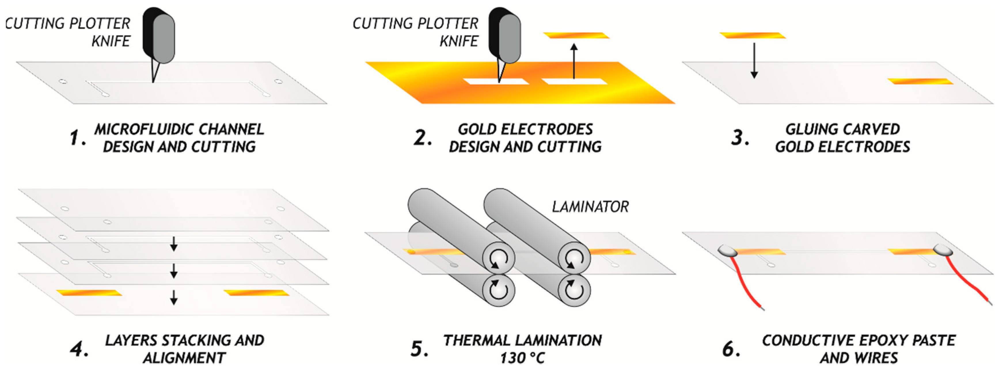
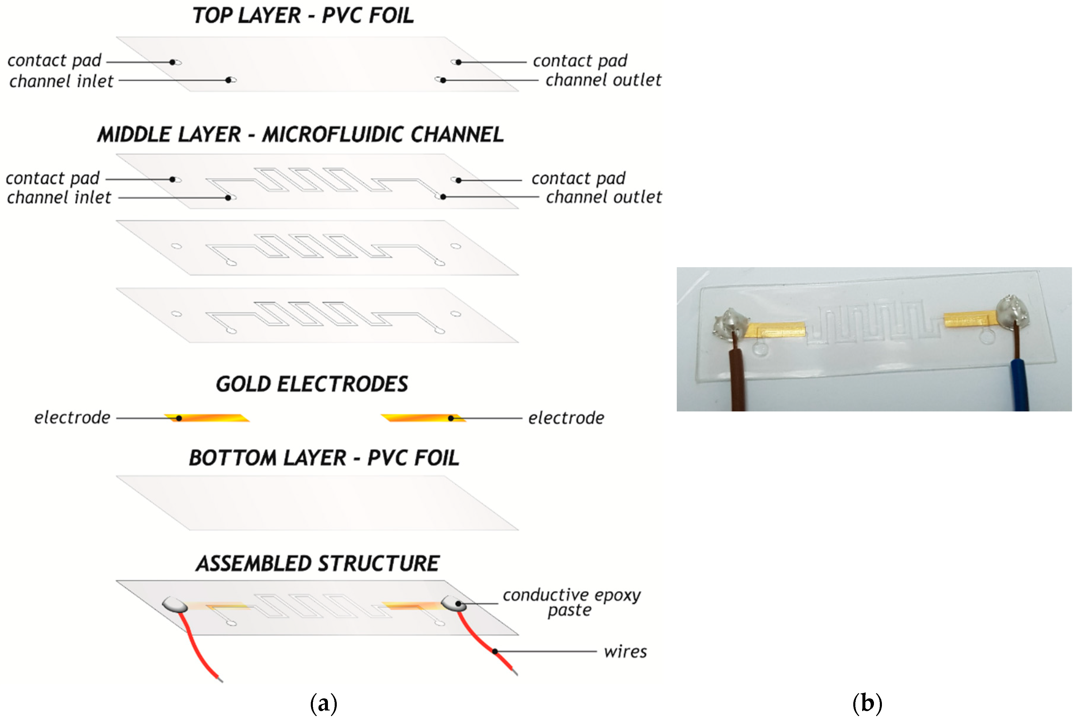
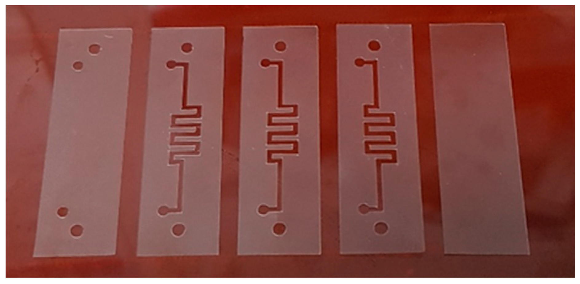
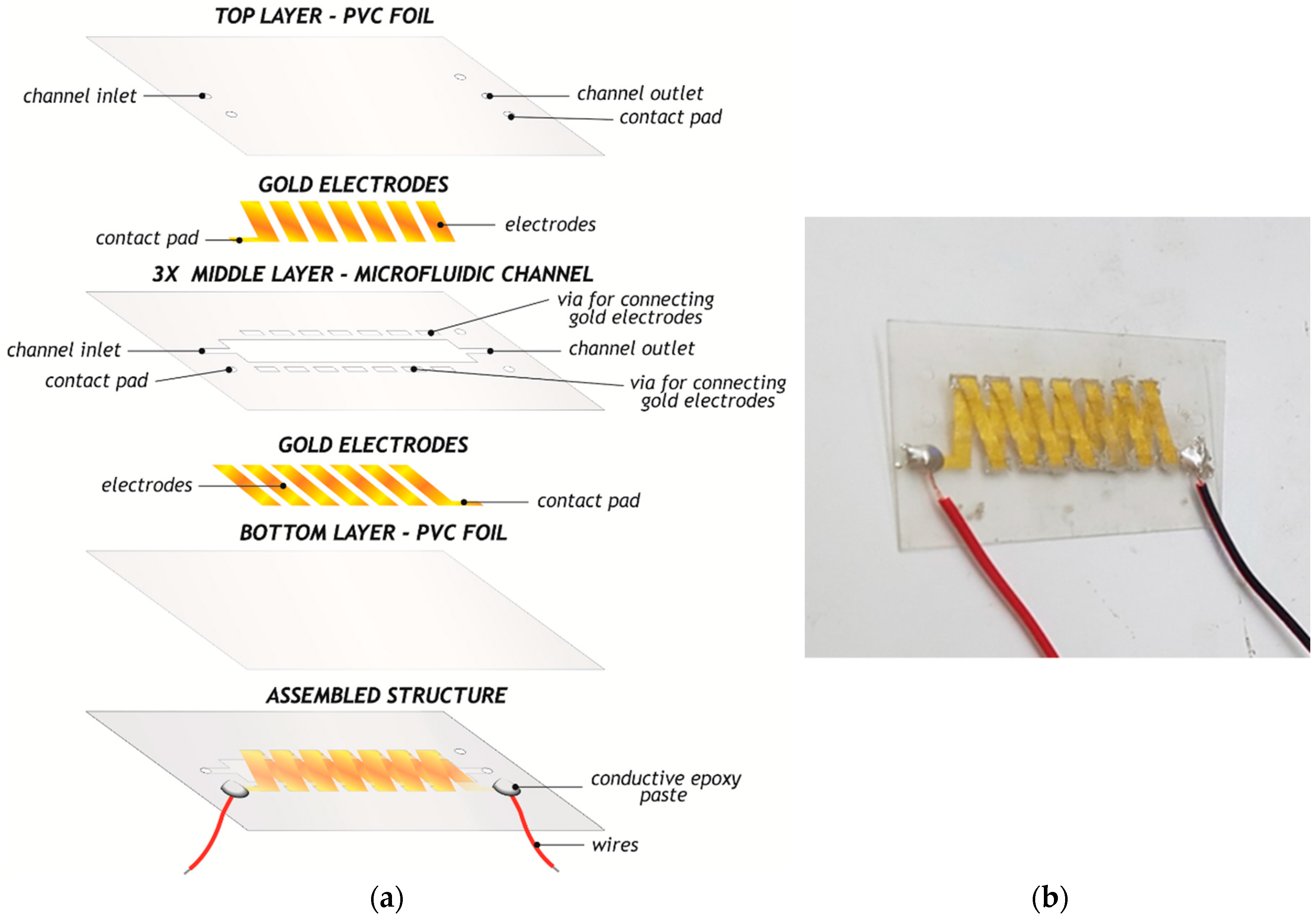
We here present the design, fabrication, and characterization of four fundamental circuit elements—R, L, C, and M. These components were fabricated using a rapid prototyping xurography technique, which is based on creating the different geometrical shapes of components in PolyVinyl Chloride (PVC) foils and laminating them under elevated temperature and pressure. Gold leaves were used as a conductive material, and after cutting separate layers in the desired pattern, multi-layered compact electronic structures were obtained. Electrical parameters were determined for all fabricated components, using impedance spectroscopy and I–V measurements. Resulting performances were better or comparable with previously published reports of components manufactured using sophisticated and costly technologies. The potential application domains of the proposed elements are: (1) development of a parallel world of microfluidics electronics using two-terminals components; (2) sensors’ applications, where in the channel can be injected some suspension, for example a drug; (3) inductive structures can be applied in microfluidic transformers with ferrofluid instead of a ferrite core between primary and secondary coils; and (4) in neuromorphic circuits (memristors are key elements in these circuits which can mimic brain behavior).

2. Materials and Methods

Four components presented in this paper were fabricated using a very precise xurography technique. Xurography is a rapid prototyping, computer-controlled method which employs a knife plotter to create microstructures of different geometries into thin foils or layers. A schematic illustrating the main steps of pattern transfer using xurography technique can be seen in Figure 1. It enables lamination of multi-layered structures mechanically carved from pressure sensitive and thermal activated adhesive foils in a very short period of time, without the necessity for costly clean room facilities.

2.1. Resistor Design

The resistors were composed of three layers. The substrate was PVC foil, on which the gold electrodes for contacts were glued. The middle layer was formed from foil and contained the microfluidic channels. We designed three types of resistors in the meander shape, creating different length channels (10 mm, 15 mm and 20 mm in the x-axis) to provide varying values of resistance. The top layer, also of PVC foil, contained the inlet, outlet, and contact pads. The design of the complete structure is illustrated in Figure 2a, and one of the fabricated microfluidic resistors is shown in Figure 2b. The total dimensions of this structure are 5 cm × 2 cm. Figure 3 shows carved separate layers of PVC foils. The width of the microfluidic channel was 1 mm, whereas the diameter of the holes was 2 mm. For the purpose of testing these resistors we used liquid dielectric materials—transformer oils and synthetic oil. Transformer oil is a petroleum based insulating oil with high electrical resistivity stable at room, but also at high temperatures. This liquid dielectric can prevent oxidation and support heat transfer in surrounding environment. Synthetic oil (or motor oil) is artificially made from chemical compounds and has a usual role as a lubricant. In this paper, these two liquid dielectrics were selected due to the possibility to be injected in microfluidic channels and the capability of increasing resistance of the component.

2.2. Inductor Design

The inductor was designed in the solenoid form with 7 turns. The Autocad software package was used for drawing patterns for each layer. The xurography technique uses a cutter plotter to mechanically cut each layer of the solenoid structure in PVC foil. Graphtech pro studio software was used to control the cutting process using a computer and the cutter plotter. The complete structure was composed of 5 layers. At the bottom, PVC foil was used as a substrate. After that came a layer incorporating the bottom part of the solenoid electrode structure. The middle layer contained a microfluidic channel for injection of ferrofluid (liquid magnetic material) which exactly represents the solenoid core, in order to increase the total inductance of the proposed structure. The dimensions of the channel were 4 cm × 0.8 cm. The fourth layer included the upper part of the conductive electrodes. Finally, the fifth layer contained holes for inlet and outlet of fluid, as well as pads for connecting wires from each terminal of the solenoid structure. Conductive gold segments in the second and fourth layer were electrically connected with silver paste. The design of all layers is shown in Figure 4a, whereas Figure 4b depicts the complete fabricated inductive structure.
The separate layers for fabrication of solenoid inductor, cut in PVC, and gold conductive segments can be seen in Figure 5. We used foils with a thickness of 80 μm. Each conductive segment had dimensions of 2.5 mm × 15 mm. The thickness of the gold segments was around 10 µm. Separate layers were stacked and laminated together using a laminator at 130 °C and the fabricated two-terminals inductor is shown in Figure 4b. The total dimensions of this microfluidic inductor were 5.5 cm × 3.6 cm.

2.3. Capacitor Design

We designed a parallel plate capacitor with two gold electrodes, between which is the space for the microfluidic channel, filled afterwards with liquid dielectric. The fabricated structure is presented in Figure 6, whereas the separate layers can be seen in Figure 7. The capacitor is composed of five layers. The bottom PVC foil layer has a role of substrate, and a contact from the bottom electrode of the capacitor is created on this layer. The next layer consists of the electrode. In the middle layer, the microfluidic channel was created. The fourth layer is comprised of the second plate electrode, and finally the fifth layer is for the inlet, outlet, and contact for the second electrode. The dimensions of the gold electrodes are 4 cm × 2 cm and the total dimensions of the fabricated structure are 5 cm × 3 cm. The distance between electrodes is equal to the thickness of one PVC foil, which is around 80 μm.

2.4. Memristor Design

The memristor is designed similarly to the resistor, but with a straight microfluidic channel. We analyzed the device with the length of the channel equal to 5 mm, and width of 1.4 mm. As a typical active material for memristors is TiO2, we used TiO2 nanopowder (as a 1% solution) and injected this solution into the microfluidic channel using a syringe. Figure 8 depicts the appearance of the fabricated memristor with 5 mm channel length. The total dimensions of the fabricated memristors were 5 cm × 2 cm.

3. Results and Discussion

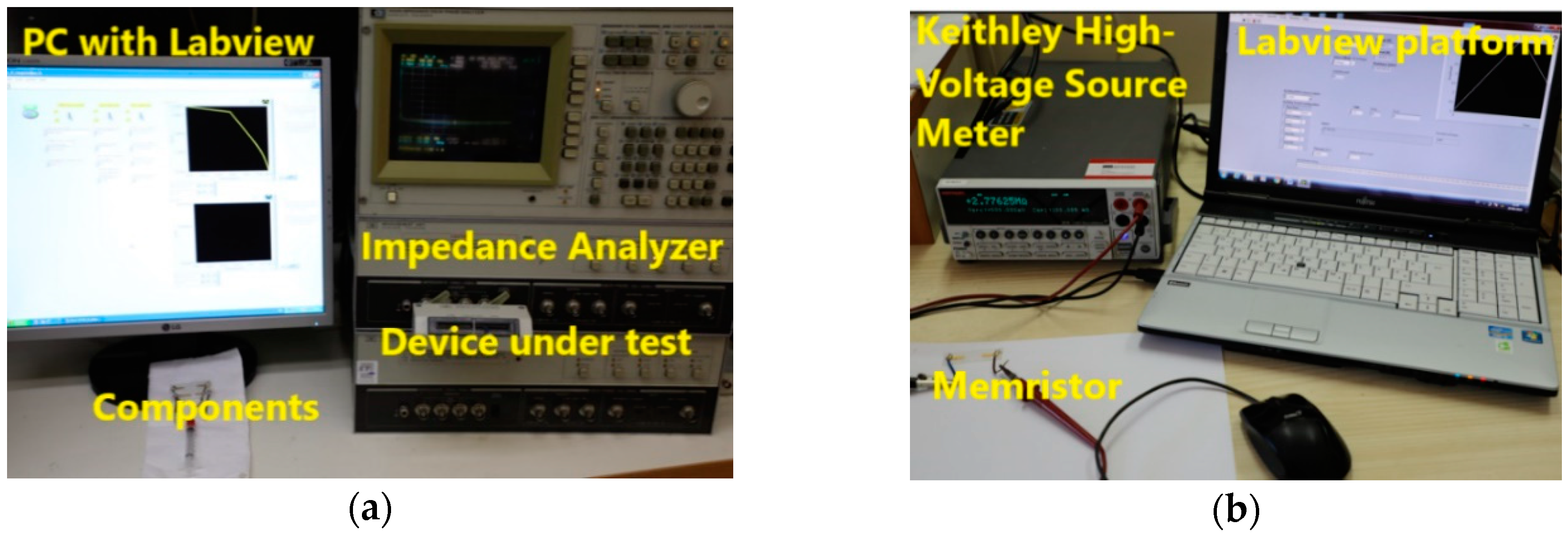
For testing the described components, we used an Impedance Analyzer HP4194A as well as Keithley 2410 High-Voltage Source Meter controlled with the LabVIEW platform. Part of the experimental setup can be seen in Figure 9.
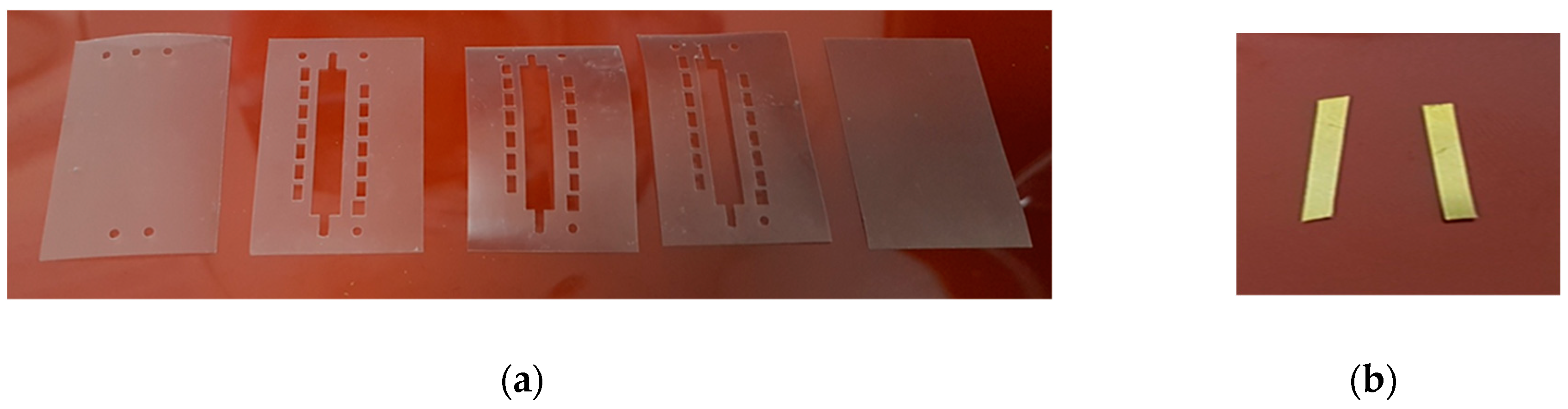
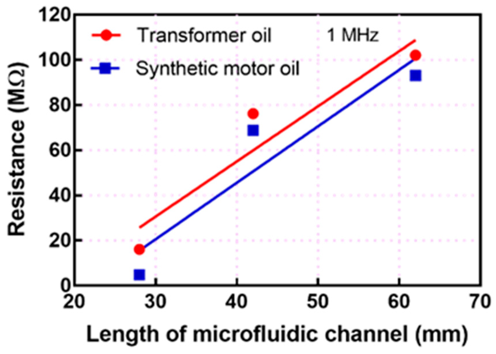
The three types of fabricated resistors were tested through the injection of transformer oil as a liquid material into the meander-shaped microfluidic channel. The measured resistance for these three cases of different length channels are presented in Figure 10. From Figure 10, it can be concluded that resistance is increased with increasing the length of the channel, which is in accordance with the equation: R = ρl/A, where ρ is the resistivity of the applied dielectrics, l is the length of the microfluidic channels, and A is the surface area (width of the channel × thickness of the channel). The total length of the channels for three types of fabricated structures were: 28 mm, 42 mm, and 62 mm. Transformer oil has higher resistivity than synthetic (motor oil) and, as a consequence, higher resistance value for the same channel length.
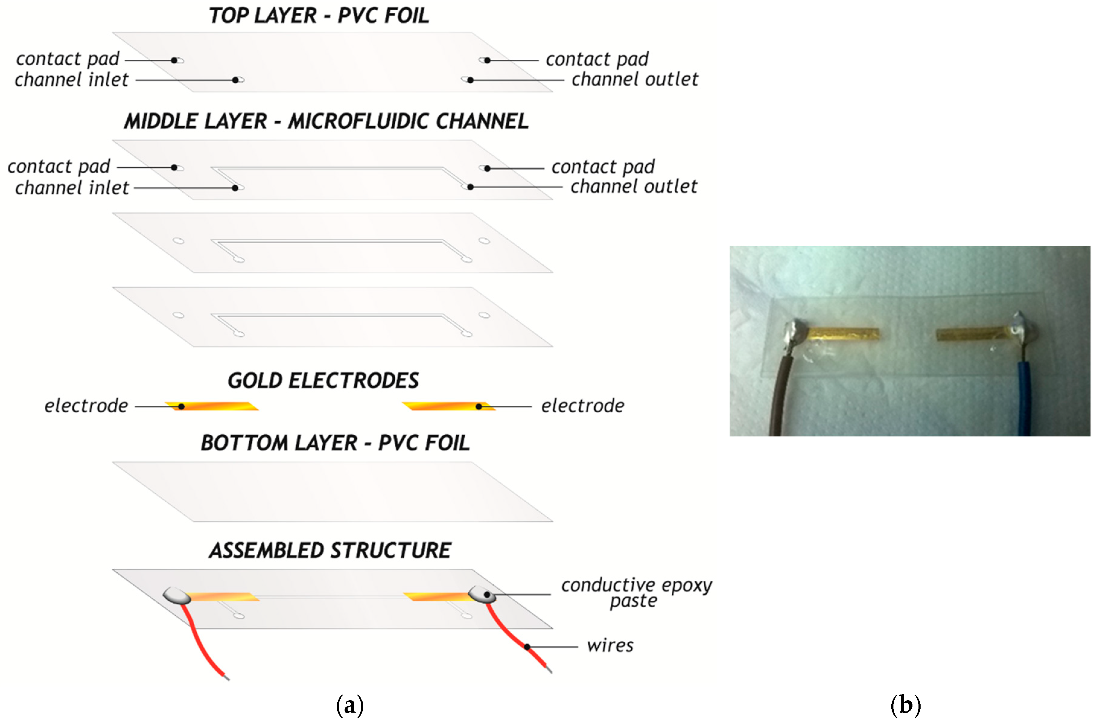
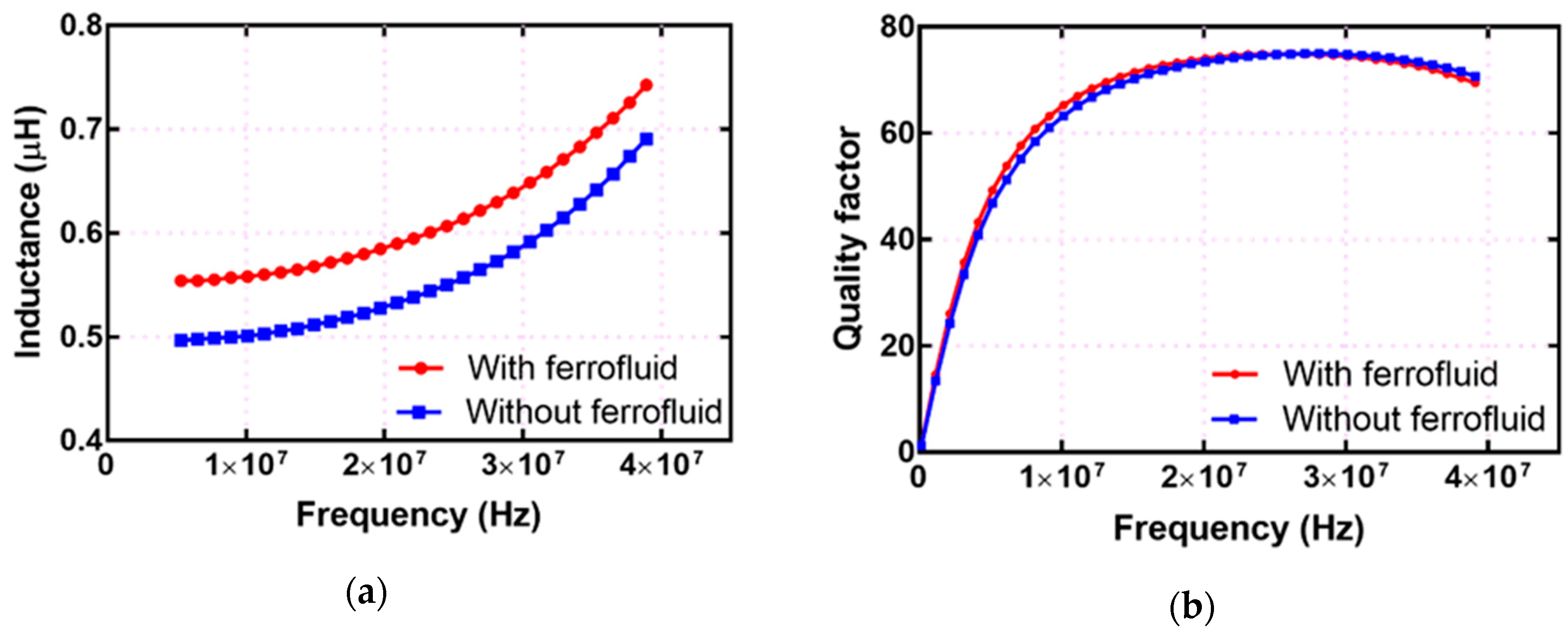
For the inductor, we studied the solenoid structure to achieve the best coupling between coils, which would result in higher mutual inductance and, consequently, higher total inductance of the component. In the channel, the liquid magnetic material—ferrofluid was injected in order to additionally increase the total inductance according to the following expression, L = A N 2 μ 0 μ r l , where A is cross-section area, N is number of turns, μ 0 = 4 π 10 7 N A 2 is the permeability in vacuum, μ r is the relative permeability of ferrofluid, and l is the length of the channel equal to 4.5 cm.
The measured inductance and quality factor, without and with ferrofluid inside the channel, are presented in Figure 11. The total inductance is around 500 nH at the frequency of 10 MHz with an empty channel, whereas this value is equal to 560 nH with ferrofluid material inside of the channel, having the role of the liquid core for the solenoid. This is an approximately 12% increase in the total inductance. The advantage of our approach is that this increase in total inductance is not paid by increasing the weight and size of the component, which is usually the case in conventional ferrite-based inductors and transformers. The bulkiest part of the inductive components in classical electronics is the magnetic core. On the contrary, in microfluidics-based electronics we used a very small amount of liquid and the weight of the component changed can be measured in μg. The maximum value obtained for the quality factor was 75 at a frequency equal to 26 MHz. This maximum value was higher than the value published in [8], which was 71.
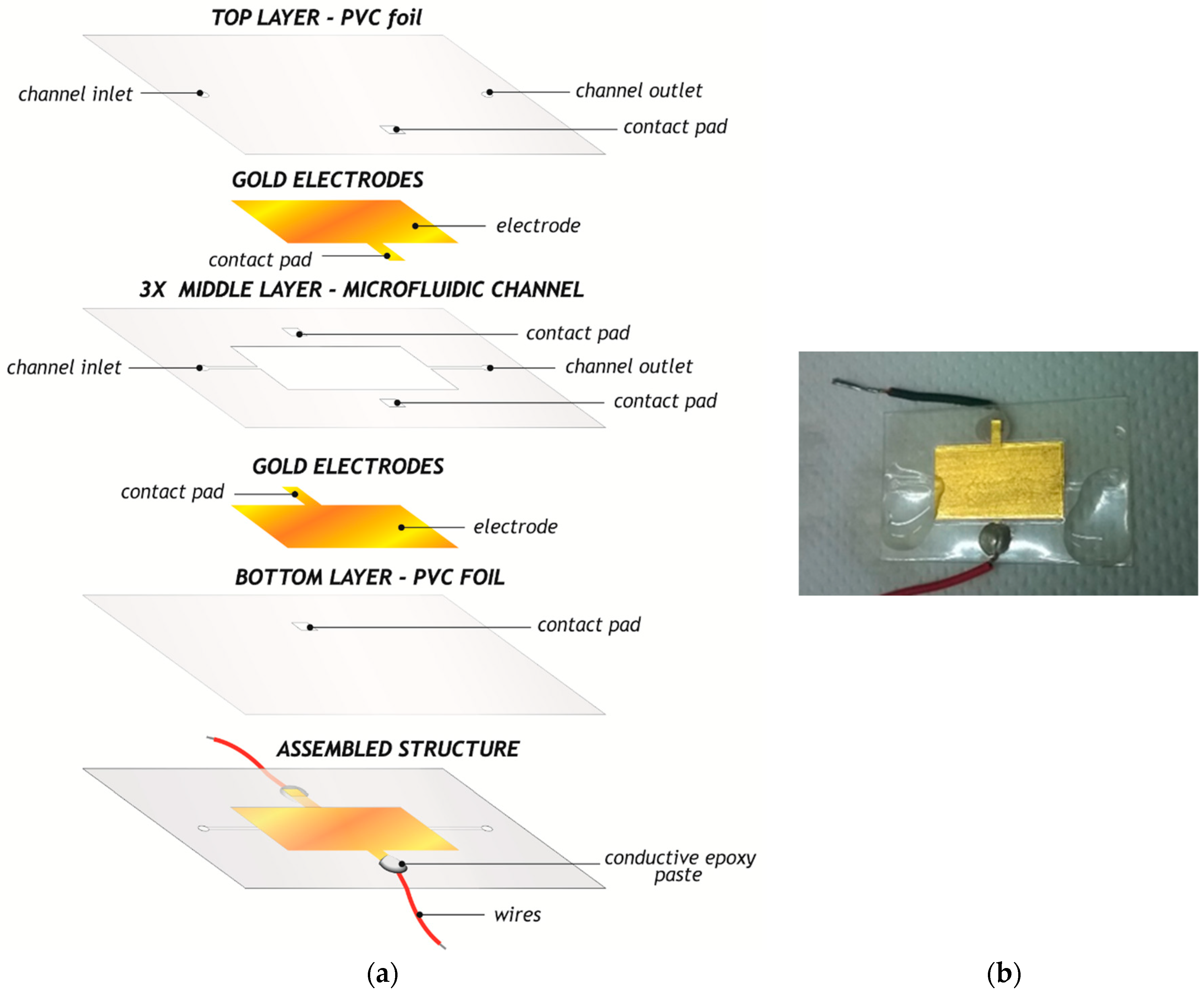
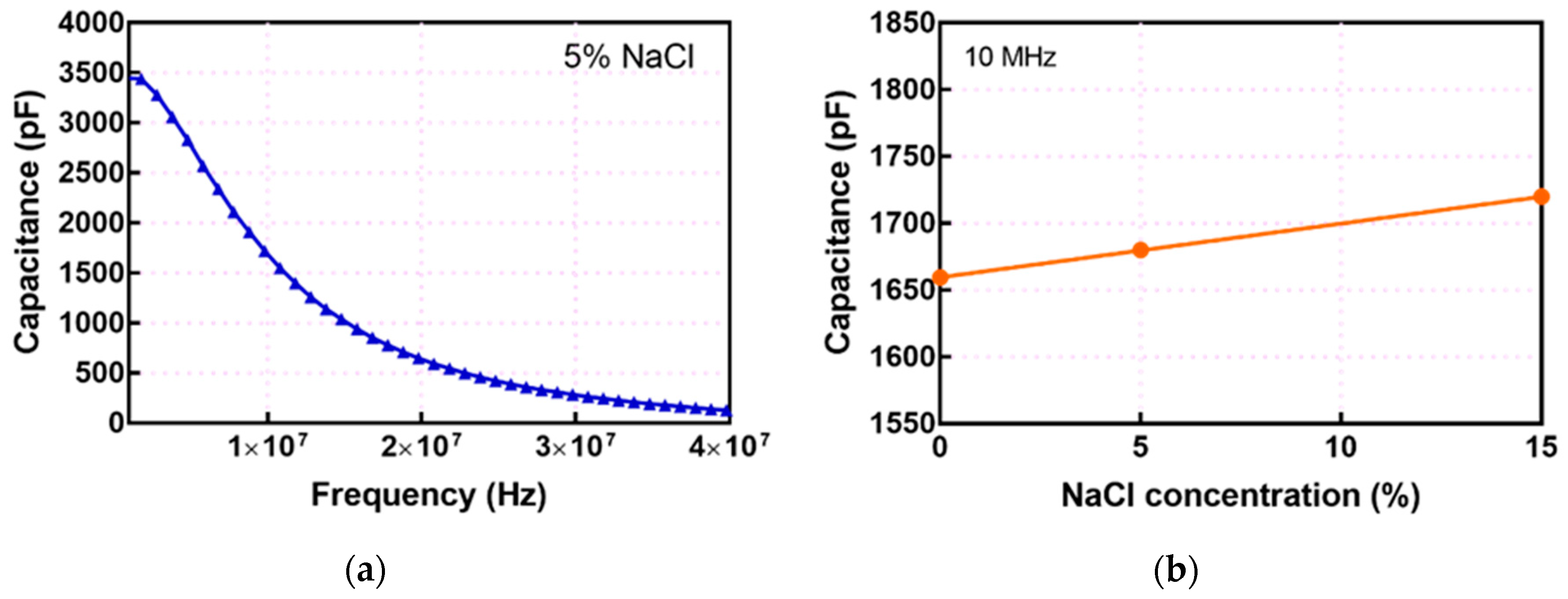
To test the capacitor, a solution of NaCl in different concentrations was injected into the microfluidic channel. In this way, the dielectric constant of the parallel plate capacitor was increased according to the formula C = ε 0 ε r   A d , where ε 0 = 8.85 × 10 12 F M , ε r is the relative permittivity of dielectric inside of the channel, A is the surface area of electrodes, and d is the distance between them. Measured capacitance as a function of frequency for different concentrations of NaCl as a parameter is shown in Figure 12. A higher concentration of NaCl was associated with a higher dielectric constant and increasing capacitance, as can be seen in Figure 12b, presented at a constant frequency point of 10 MHz. Measured capacitance decreased with increasing frequency, bearing in mind that the same trend has a dielectric constant, due to different types of polarization which can be noticed from low frequencies towards the high frequency range.
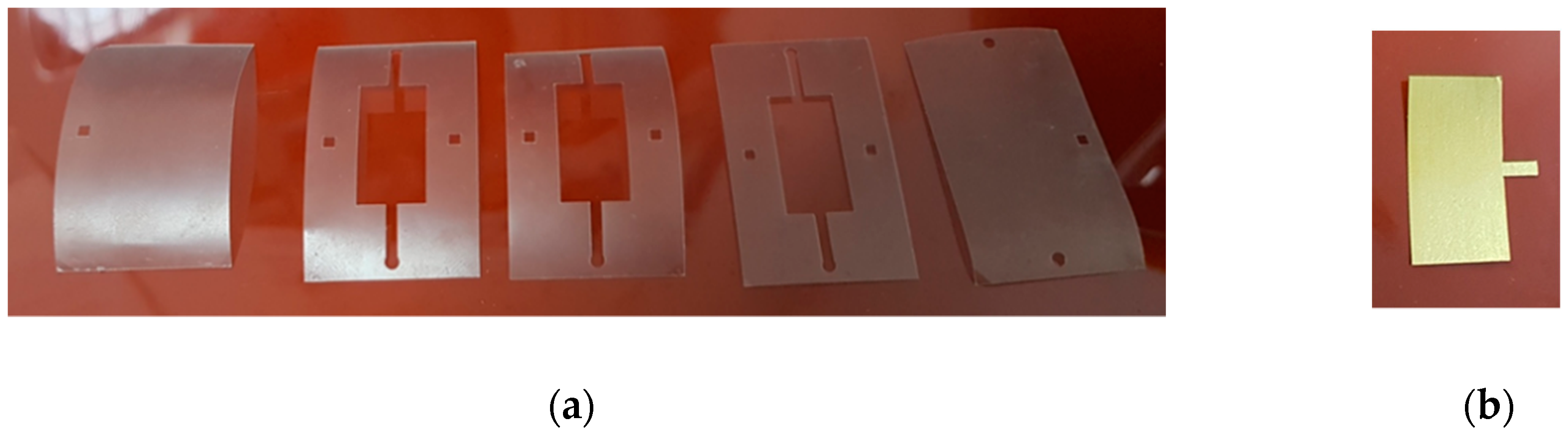
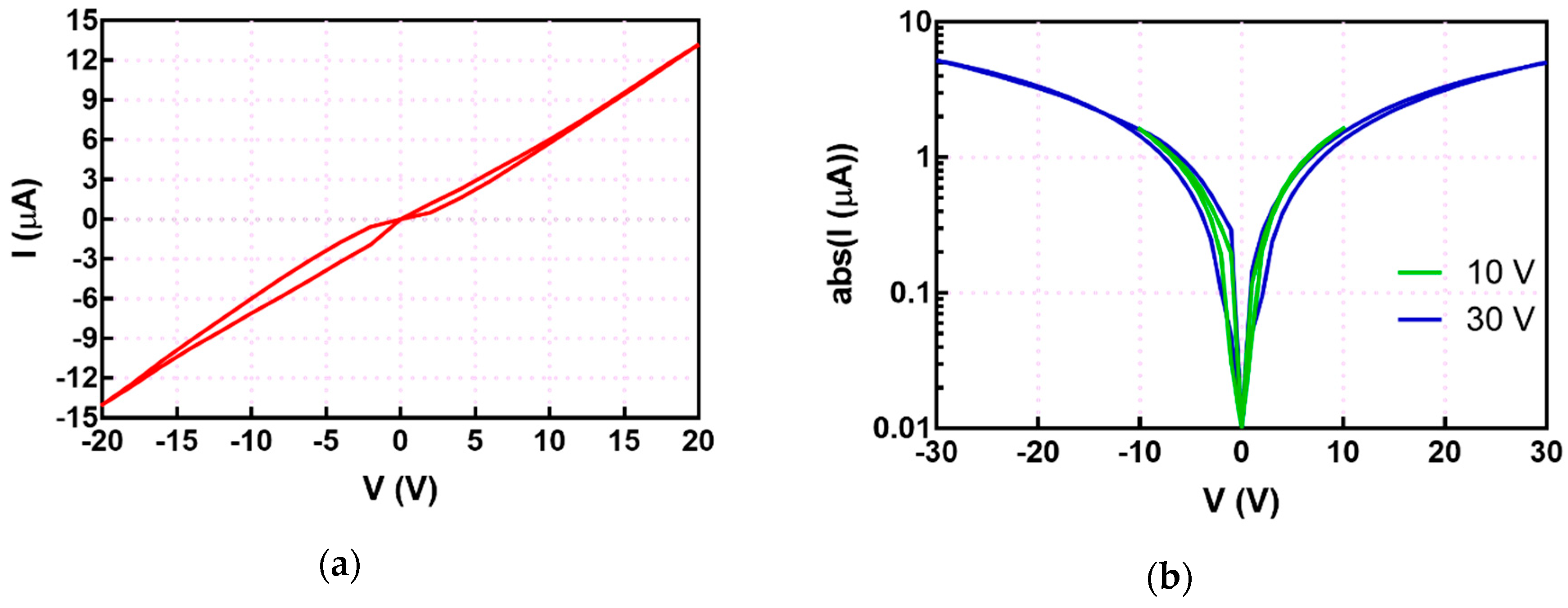
For memristors, a solution of TiO2 nanopowder (1%) was prepared and injected into the straight line-shaped microfluidic channel. Measurements were performed using Keithley 2410 High-Voltage Source Meter controlled with the LabVIEW platform (ambient conditions, temperature ~ 300   K ). The actuation voltage was a bipolar voltage waveform (0 V → Vmax→ 0→ –Vmax→ 0 V), triangular waveform, with a sweep speed of 1 V/ms and voltage amplitude of 20 V, as can be seen in Figure 13a. Ground (referent) potential is connected to the microfluidic device inlet, while positive voltage is connected to the device’s outlet, as shown in Figure 9b. Transition from High Resistive State (HRS)/ON state to Low Resistive State/OFF state occurs for negative voltage polarity. The obtained hysteresis loop in I–V characteristic (determined by the direction of switching) belongs to the non-crossing type (NCT), or tangential hysteresis loop, i.e., two parts of the loop only touch each other, and do not intersect [22]. According to measured results, presented in Figure 13a, we estimated OFF-to-ON resistive ratio around a factor of 2. Unlike other reported results in the literature for microfluidic memristors [20,21,22], the current–voltage characteristics of the fabricated device exhibited hysteresis for both positive and negative polarities of actuation voltage; consequently it represents a bipolar class of resistive switching devices. Furthermore, existing loops in the 1st and 3rd quadrants of the I–V plane showed similar lobe area (close to symmetric loops), which indicates low dissipation, i.e., lower Joule heating compared to results reported in the literature [20,21,22]. Increasing the amplitude of actuation voltage, the width of hysteresis loops was increased in both 1st and 3rd quadrant, indicating improvement in OFF-to-ON resistive ratio and potential application of these devices as multilevel memristors, Figure 13b.
This observation can be explained by the symmetric structure of the device as well as low-Ohmic contact between electrodes achieved by the combination of Au electrodes and silver paste contacts between the device and the wires.
The main advantages of the presented components can be summarized as follows: (1) rapid and precise applied xurographic technology; (2) robust and cost-effective components; (3) realization of discrete two-terminal basic electronics components in microfluidic world; (4) optical transparency and mechanical flexibility of fabricated components. If we can talk about some disadvantages of the proposed components, they might be: (1) limited resolution imposed by applied technology, which has consequences in total dimension of these fundamental circuit elements; (2) limited choice of conductive materials (gold, copper, aluminum) which can be used as materials in leaf form or foil structure.

4. Conclusions

In this work we have connected the fields of microfluidics and electronics, presenting the design, fabrication and testing of four fundamental circuit elements, R, L, C, and M, the characteristics of which are improved by injecting the appropriate fluid into the microfluidic channels. We applied a precise, rapid prototyping xurography technique, enabling fabrication of robust, mechanically flexible, transparent and lightweight components. This method enables the manufacturing of electronic components very rapidly, using cost-effective equipment and without a requirement for clean room facilities. We estimate the entire cost of fabricating the presented components is around 0.6 EUR per component, and this price can be reduced in the case of using higher dimensions of PVC foils than A4 format (used in this work). The proposed components will further advance the development of the electronics and microfluidics industries, as well as have potential to make revolutionary changes in the field of passive electronic components.

Author Contributions

Investigation, M.P., N.S. and M.R.; methodology, G.S.; resources, G.S.; visualization, D.K.; writing—original draft, G.S., and N.S.

Funding

Results presented in this article received funding from the European Union’s Horizon 2020 research and innovation program under the Marie Skłodowska-Curie grant agreement no. 690876–MEDLEM as well as being partly supported within project no. III45021.

Acknowledgments

Authors would like to thank colleagues from Faculty of Technology, University of Novi Sad for shaking some solutions used in this work.

Conflicts of Interest

The authors declare no conflicts of interest.

References

  1. Shan, S.D.; Sheng, C.Y.; Xian, C.Z.; Jun, L.; Young, S. Toward the complete relational graph of fundamental circuit elements. Chin. Phys. B 2015, 24, 068402. [Google Scholar] [CrossRef] [Green Version]
  2. Strukov, D.B.; Snider, G.S.; Stewet, D.R.; Williams, S. The missing memristor found. Nature 2008, 453, 80–83. [Google Scholar] [CrossRef] [PubMed]
  3. Fan, Y.-J.; Wu, Y.-C.; Chen, Y.; Kung, Y.-C.; Wu, T.-H.; Huang, K.-W.; Sheen, H.-J.; Chiou, P.-Y. Three dimensional microfluidics with embedded microball lenses for parallel and high throughput multicolor fluorescence detection. Biomicrofluidics 2013, 7, 044121. [Google Scholar] [CrossRef] [PubMed]
  4. Chen, Y.; Wu, T.-H.; Kung, Y.-C.; Teitell, M.A.; Chiou, P.-Y. 3D pulsed laser-triggered high-speed microfluidic fluorescence-activated cell sorter. Analyst 2013, 138, 7308–7315. [Google Scholar] [CrossRef] [PubMed] [Green Version]
  5. Chirasatitsin, S.; Kojić, S.; Stojanović, G. Optimization of microchannel fabrication using xerographic technique for microfluidic chips. In Proceedings of the Scientific Conference ETIKUM’2017, Novi Sad, Serbia, 6–8 December 2017. [Google Scholar]
  6. Cheng, S.; Wu, Z. Microfluidic electronics. Lab Chip 2012, 12, 2782–2791. [Google Scholar] [CrossRef] [PubMed]
  7. Godwin, L.A.; Deal, K.S.; Hoepfner, L.D.; Jackson, L.A.; Easley, C.J. Measurement of Microchannel Fluidic Resistance with a Standard Voltage Meter. Anal. Chim. Acta 2013, 758, 101–107. [Google Scholar] [CrossRef] [PubMed]
  8. Lazarus, N.; Bedair, S.S.; Smith, G.L. Creating 3D Printed Magnetic Devices with Ferrofluids and Liquid Metals. Addit. Manuf. 2019, 26, 15–21. [Google Scholar] [CrossRef]
  9. Banitorfian, F.; Eshghabadi, F.; Manaf, A.A.; Noh, N.M.; Mustaffa, M.T. A Novel Ferrofluids-Based High-Tuning High-Q Variable Solenoid Inductor for Frequency-Reconfigurable Circuits Applications. In Proceedings of the IEEE International Circuits and Systems Symposium (ICSyS), Langkawi, Malaysia, 2–4 September 2015. [Google Scholar]
  10. Wu, Y. Detection of foreign particles in lubrication oil with a microfluidic chip. Ind. Lubr. Tribol. 2018, 70, 1381–1387. [Google Scholar] [CrossRef]
  11. Wu, Y.; Zhang, H. Research on the effect of relative movement on the output characteristic of inductive sensors. Sens. Actuators A Phys. 2017, 267, 485–490. [Google Scholar] [CrossRef]
  12. Andersson, M.; Wilson, A.; Hjort, K.; Klintberg, L. A microfluidic relative permittivity sensor for feedback control of carbon dioxide expanded liquid flows. Sens. Actuators A Phys. 2019, 285, 165–172. [Google Scholar] [CrossRef]
  13. Habbachi, N.; Boussetta, H.; Boukabache, A.; Kallala, M.A.; Pons, P.; Besbes, K. Fabrication and modelling of a capacitor microfluidically tuned by water. IEEE Electron Device Lett. 2016, 38, 277–280. [Google Scholar] [CrossRef]
  14. Habbachi, N.; Boussetta, H.; Boukabache, A.; Kallala, M.A.; Pons, P.; Besbes, K. Design and fabrication of a continuously tuned capacitor by microfluidic actuation. J. Micromech. Microeng. 2018, 28, 035012. [Google Scholar] [CrossRef]
  15. Kim, M.G.; Alrowais, H.; Pavlidis, S.; Brand, O. Size-Scalable and High-Density Liquid-Metal-Based Soft Electronic Passive Components and Circuits Using Soft Lithography. Adv. Funct. Mater. 2017, 27, 1604466. [Google Scholar] [CrossRef]
  16. Liu, S.; Sun, X.; Hildreth, O.J.; Rykaczewski, K. Design and characterization of a single channel two-liquid capacitor and its application to hyperelastic strain sensing. Lab Chip 2015, 15, 1376–1384. [Google Scholar] [CrossRef] [PubMed]
  17. Liang, Y.; Ma, M.; Zhang, F.; Liu, F.; Liu, Z.; Wang, D.; Li, Y. An LC Wireless Microfluidic Sensor Based on Low Temperature Co-Fired Ceramic (LTCC) Technology. Sensors 2019, 19, 1189. [Google Scholar] [CrossRef] [PubMed]
  18. Zeng, L.; Zhang, H.; Zhao, H.; Yu, Z.; Teng, H. Novel Inductance/Capacitance Microfluidic Chip for the Multi-Contamination Detection in Marine Hydraulic Oil. In Proceedings of the Prognostics and System Health Management Conference (PHM-Harbin), Harbin, China, 9–12 July 2017. [Google Scholar]
  19. Koo, H.J.; So, J.H.; Dickey, M.D.; Velev, O.D. Towards All-Soft Matter Circuits: Prototypes of Quasi-Liquid Devices with Memristor Characteristics. Adv. Mater. 2011, 16, 3559–3564. [Google Scholar] [CrossRef] [PubMed]
  20. Hadisa, M.N.S.; Manafa, A.A.; Ngalimc, S.H.; Hermand, S.H. Fabrication and characterisation of fluidic based memristor sensor for liquid with hydroxyl group. Sens. Biosens. Res. 2017, 14, 21–29. [Google Scholar]
  21. Sheng, Q.; Xie, Y.; Li, J.; Wang, X.; Xue, J. Transporting ionic-liquid/water mixture in a conical nanochannel: A nanofluidic memristor. Chem. Commun. 2017, 53, 6125–6127. [Google Scholar] [CrossRef] [PubMed]
  22. Biolek, Z.; Biolkova, D.; Biolkova, V.; Kolka, Z. Comments on Pinched Hysteresis Loops of Memristive Elements. Radioengineering 2015, 24, 962–967. [Google Scholar] [CrossRef]
Figure 1. The main fabrication steps in fabrication of a microfluidic component by means of xurography technique: microfluidic channel cutting in PVC foil, electrodes cutting in gold layer, layers stacking and alignment, as well as their lamination.
Electronics 08 00960 g001
Figure 2. (a) Design of multi-layered resistor: bottom—PVC layer with gold electrodes, middle layer—microfluidic channel, top layer—for inlet, outlet and electrical terminals, (b) one of the fabricated microfluidic resistors, after lamination.
Electronics 08 00960 g002
Figure 3. Separate layers of PVC foils: one top layer, three middle layers with microfluidic channel, and bottom layer as a substrate.
Electronics 08 00960 g003
Figure 4. (a) Design of all layers of the inductive solenoid structure with microfluidic channel in the middle layers, (b) fabricated microfluidic solenoid inductor with two terminals.
Electronics 08 00960 g004
Figure 5. (a) Separate layers of PVC foil for inductor fabrication: bottom—PVC layer, middle layer—microfluidic channel, top layer—for inlet, outlet and electrical terminals, (b) conductive segments for solenoid turns from one side as well as from another side of the microfluidic channel.
Electronics 08 00960 g005
Figure 6. (a) Design of all layers of the capacitive structure: PVC layer with two gold electrodes of the capacitor, middle layer—microfluidic channel, top layer—for inlet, outlet and electrical terminals, (b) fabricated microfluidic capacitor with fluid inside the channel.
Electronics 08 00960 g006
Figure 7. (a) Separate PVC layers of microfluidic capacitor, (b) gold electrodes for parallel plate capacitor.
Electronics 08 00960 g007
Figure 8. (a) Design of all layers of the memristive structure: bottom—PVC layer with gold electrodes, middle layer—microfluidic channel, top layer—for inlet, outlet, and electrical contact pads, (b) fabricated microfluidic memristor.
Electronics 08 00960 g008
Figure 9. Experimental set-up with: (a) Impedance Analyzer HP4194A for experimental testing of microfluidic resistor, inductor, and capacitor, (b) Keithley 2410 for experimental determination of microfluidic memristor characteristics.
Electronics 08 00960 g009
Figure 10. Resistance as a function of the microfluidic channel length, for transformer oil and synthetic motor oil as resistive liquid materials inside the channel.
Electronics 08 00960 g010
Figure 11. (a) Measured inductance, (b) measured quality factor, without and with ferrofluid inside the channel of microfluidic solenoid inductor.
Electronics 08 00960 g011
Figure 12. Capacitance of microfluidic capacitor as a function of: (a) frequency for 5% NaCl solution, (b) different concentration of NaCl solution inside the channel.
Electronics 08 00960 g012
Figure 13. Current–Voltage (I–V) characteristics of fabricated microfluidic memristor, based on liquid TiO2 inside of the channel, for voltage amplitude, (a) 20 V, (b) 10 V and 30 V.
Electronics 08 00960 g013

