Accelerometer-Based Gyroscope Drift Compensation Approach in a Dual-Axial Stabilization Platform


1
College of Automation, Harbin Engineering University, Harbin 150001, China
2
National Key Laboratory of Science and Technology on Aerospace Intelligence Control, Beijing Aerospace Automation Control Institute, Beijing 100854, China
*
Author to whom correspondence should be addressed.
Electronics 2019, 8(5), 594; https://doi.org/10.3390/electronics8050594
Submission received: 26 April 2019
/
Revised: 16 May 2019
/
Accepted: 21 May 2019
/
Published: 27 May 2019
(This article belongs to the Section Microelectronics)
Abstract
:An accelerometer-based gyro drift compensation approach in a dual-axial stabilization platform is introduced in this paper. The stabilization platform consists of platform framework, drive motor, gyro and accelerometer module and contorl board. Gyro is an angular rate detecting element to achieve angular rate and rotation angle of the dynamic platform system. However, the platform system has an unstable factor because of the drift of gyro. The main contribution of this paper is to implement a convenient gyro drift compensation approach by using the accelerometer. In contrast to a kalman filtering method, this approach is simpler and practical due to the high-precision characteristic of the accelerometer. Data filtering algorithm and limit of threshold setting of total acceleration values are applied in this approach. The validity and feasibility of the proposed approach are evaluated by four tests under various conditions.
1. Introduction
A device which measures the attitude change of carrier by gyro and keeps a platform steady is called a gyro stabilization platform. A gyro stabilization platform has various applications in military affairs and the civil and industry fields [1,2]. It can be used in intelligent mechanical systems for smooth movements. The technology of gyro stabilization platforms belongs to inertial techniques; it can be used to detect and control inertial attitude. Recently, the high-precision laser or fiber optical gyro has been used to measure the angular rate of the carrier. However, high cost and large volume drawbacks of a laser or fiber optical gyro are the main reasons that make them unsuitable to small-scale and foundation platforms [3]. Fortunately, micro electro mechanical system (MEMS) technology is developed by semiconductor manufacting technology. The MEMS inertial sensor is generated by an inertia principle and has the advantages of small size, low cost and low power consumption. It plays an important role in various navigation systems of the industrial field. The core of MEMS inertial sensor is the inertial measurement unit (IMU), which consists of a tri-axis gyro and tri-axis accelerometer to measure the angular rate and the linear acceleration of the carrier. However, gyro drift error from integral calculation in long time is not to be neglected [4,5]. Hence, a proper compensation method for gyro drift is necessary to improve the accuracy and stability of the gyro stabilization platform.
Various compensation methods have been developed for gyro drift. A method for combining the accelerometer and gyro sensors has been presented to improve the precision of epicardial motion measurement. However, This application belongs to the domain of biomedical science and the scope of its applicability is restricted within narrow limits [6]. A methodology for the calibration and the drift compensation of a wearable device with accelerometer and gyroscope is also described to improve performance of the device. This method refers to calibration and compensation steps. Compensation is completed in static drift aspect and dynamic drift aspect, so the logical algorithms are incresed [7]. Moreover, motion compensation with a single-axis gyroscope and dual-axis accelerometer for automotive SAR is presented in motion compensation systems which can cope with worse road conditions. This compensation approach is generally suited to a low rotational dynamic situation [8]. A method is applied to correct the nonorthogonality errors in some cases where the cluster design of the inertial measurement unit is inappropriate. So the computational procedure of this method is complex [9]. Gyro sensor drift compensation method by kalman filter is presented to control a mobile inverted pendulum robot system [10]. A calibration and compensation method for installation errors of accelerometer in gyroscope strap-down inertial navigation system is proposed to improve the accuracy of angular velocity [11]. The delay compensation method of tilt sensor based on the MEMS accelerometer is presented to improve the accuracy in the tilt measurement. Data fusion technique is applied in this method [12]. Drift model and compensation method for MEMS-based gyroscope which uses a wiener type recurrent neural network is described to increase the accuracy of trajectory reconstruction. However, a neural network method needs more data and takes longer to completea task than other methods [13]. Considering a gyroscope drift model is a time-varying model, the realtime parameter identification and model construction are necessary. In fact, it is difficult to realize this process. So a more feasible approach is needed to solve the problem of gyroscope drift.
The characteristic of accelerometers that have high precision and less accumulative error compared to gyro are considered in this paper. A convenient gyroscope drift compensation method for a gyroscope-stabilized platform system by using accelerometer compensation strategy is proposed. Compared with the above-mentioned methods, this approach is simple and convenient. Meanwhile, computation of some complex compensation algorithms needs longer time, but computation of the proposed method needs shorter time.
This paper is structured as follows. In Section 2, motion equations of stabilized platform are described. In Section 3, accelerometer compensation strategy is described. In Section 4, experiments are conducted, datas are simulated and results are analysed. In Section 5, the concluding remark and future work are mentioned.
2. Motion Equations of Stabilized Platforms
A stabilized platform is a device that can ensure the stability of the platform in a constant position or changing position by a specified command. According to different demands and application fileds, dual-axis or tri-axis is chosen from pitch axis, roll axis and heading axis to compose the stabilized platform. The dual-axis-stabilized platform which includes pitch axis and heading axis is addressed in this paper.
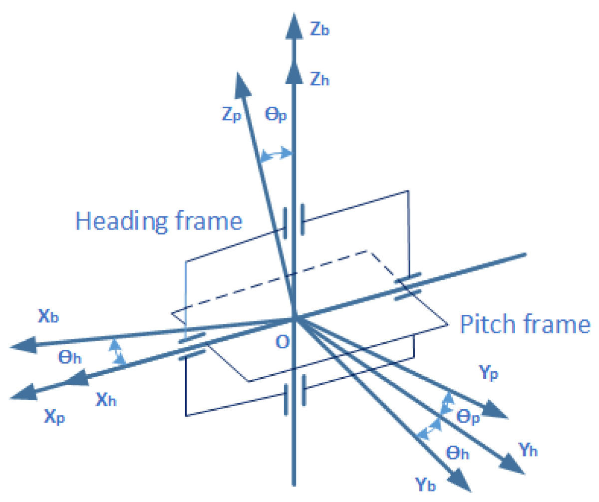
The coordinate system of dual-axis-stabilized platform is expressed in Figure 1. A stabilized platform consists of internal frame and external frame. Internal frame is a pitch frame and external frame is a heading frame. is the platform coordinate system. is the pitch frame coordinate system. is the heading frame coordinate system. is the pitch angle that rotates around the axis. is the heading angle that rotates around the axis.
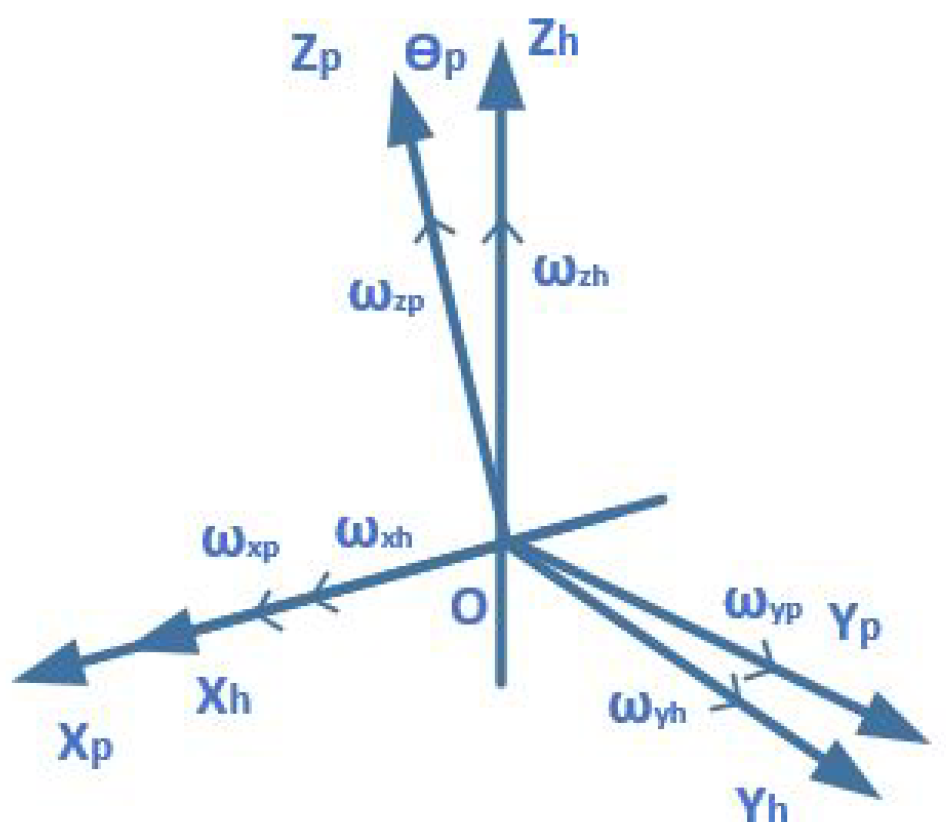
When there is disturbed angular velocity in the dynamic carrier relative to inertial space, disturbed angular velocity is transmitted to the heading axis and pitch axis of stabilized platform, which results in platform unstability. Compensation equations from kinematics analysis are necessary to isolate disturbance. The relationship between carrier coordinate and heading coordinate is described in Figure 2 when a pitch frame is separated. , and are angular velocity component that disturbed angular velocity is decomposed in each coordinate axis. Analogously, angular velocity components in heading frame coordinate axis are expressed as , and . Corresponding expressions are written as follows.
The relationship between pitch frame and heading frame can be described in Figure 3. Angular velocity components in pitch frame are expressed as , and . Accordingly, the corresponding relationship can be written as follows.
Substituting Equations (1)–(3) into the above equation. Angular velocity component of moving carrier in heading frame coordinate axis is expressed as follows.
In practice, angular velocity component of output compensation angular velocity and of stability control system in pitch frame coordinate axis are written as follows.
Consequently, angular velocity component can be expressed as follows.
The central premise of line-of-sight stabilization is that and .
Compensation angular velocity and are obtained as follows.
and are measured by gyro sensor, which is installed in pitch frame. Substituting Equations (4), (7) and (9) into Equation (15) and (16). Compensation angular velocity in pitch and heading frame are obtained and represented as follows [14].
When the above conditions are satisfied, angular motion disturbance of moving carrier is isolated and line-of-sight of camera module of stabilized platform is stabilized.
3. Accelerometer Compensation Strategy
Accelerometer measurement value is introduced to compensate the gyroscope drift in a gyroscope stabilized platform. Pitch angle of stabilized platform can be calculated by using accelerometer measurement value. Specifically, accelerometer is installed in pitch frame. Gyroscope compensation in pitch direction is considered in this paper.
Gyro drift is a slow changing and random process. Attitude angle is obtained by integral calculation of angular velocity. Attitude measurement errors are easily produced due to gyro drift. The longer work time, the greater the error [15]. To solve this problem, a gyro drift compensation method is applied to increase the accuracy of attitude estimation. Gyro drift model is represented as follows.
where is the gyro output data from the actual measurements. is the real angular velocity. b is the gyro drift.
When there is no accelerating or decelerating motion in a carrier and stabilized platform is at horizontal position, the axis of pitch frame coincides exactly with the axis of geographic coordinate system. The output of axis accelerometer is zero when carrier starts moving and stabilized platform is not at horizontal position. At this time, the output of axis accelerometer is not zero and assume it is . Pitch angle is represented as follows by using trigonometrical function [16].
Comparing this angle with pitch angle which integrates from a gyroscope signal, a compensation angle is obtained to adjust gyroscope drift by restricting and scaling.
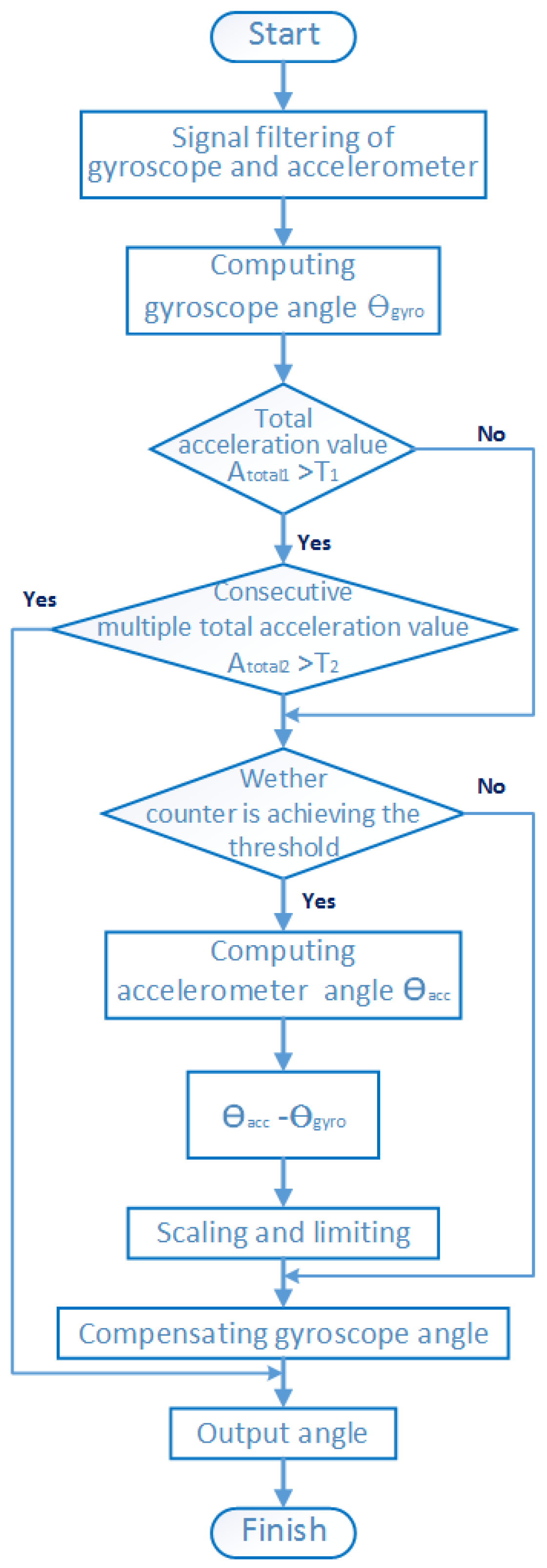
When there is continuous accelerating or decelerating motion in carrier. The output signal of accelerometer includes acceleration information of carrier, pitch angle of stabilized platform can not be extracted and compensated in this time. However, instantaneous acceleration and deceleration of carrier can be obtained by data filtering algorithm and limit of threshold setting of total acceleration value, then gyroscope compensation is completed. The detailed compensation algorithm step is described in Figure 4.
is the total acceleration value. is the consecutive multiple total acceleration value. and are the corresponding limited thresholds, respectively. An accelerometer compensation algorithm is easier and more practical than the kalman filter method. It is more applicable to a stabilized system in this paper. Specifically, the accelerometer compensation algorithm is uncomplicated compared to the mentioned methods in Section 1. Hence, run time and adjusting time of the stabilized system are short.
4. Experimental Analysis and Results
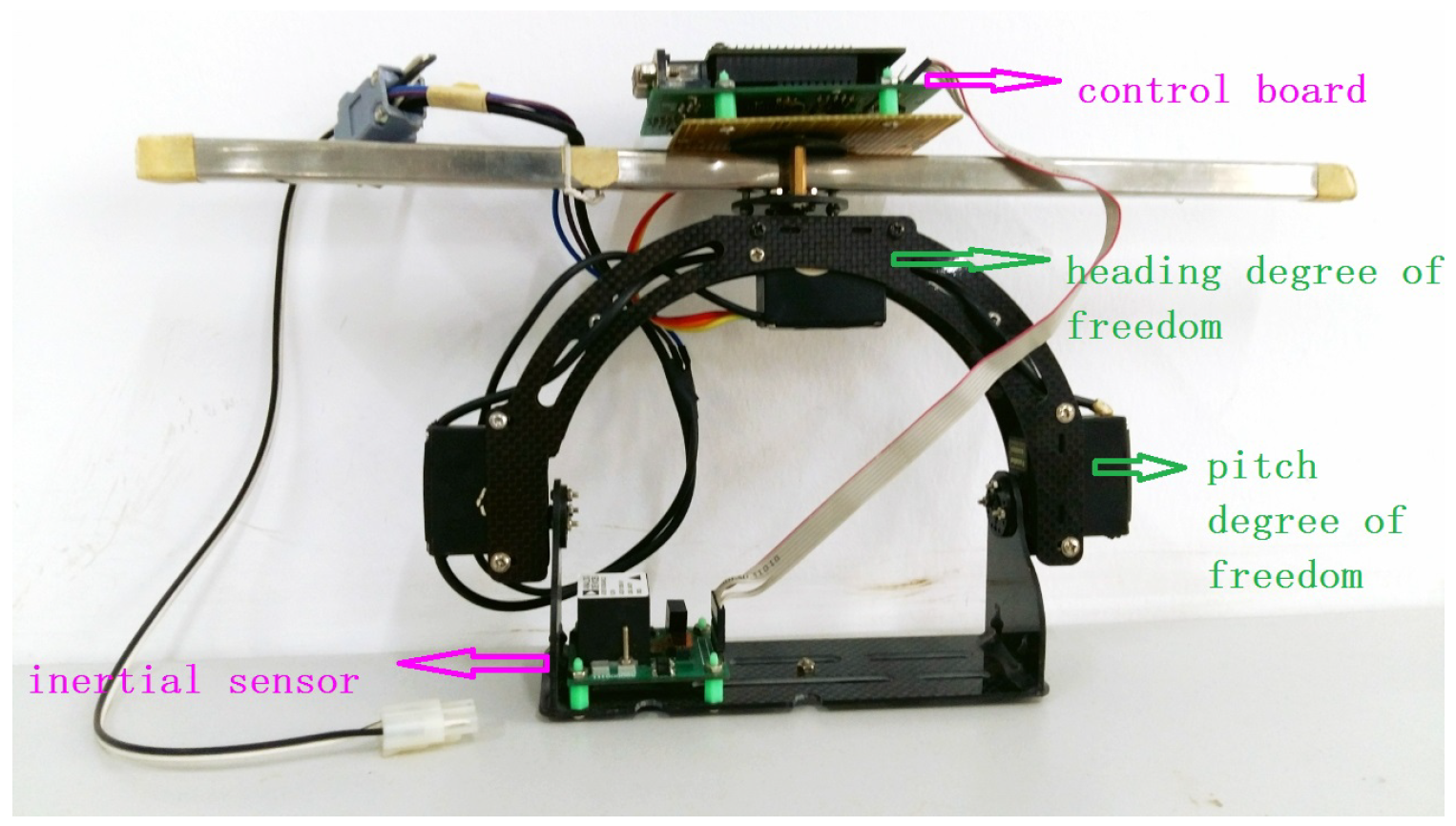
The experiment of accelerometer compensation method applied in gyroscope-stabilized platform systems is conducted in this section. Gyro and accelerometer are the main sensing device in the experiment. Gyro senses angular motion information and the accelerometer senses linear motion information. When there is no accelerating or decelerating motion, the accelerometer senses deflection of platform relative to horizontal plane and compensates gyro drift. Tri-Axis inertial sensor ADIS16350 is chosen as IMU. It involves micromechanics and mixed information technology. It provides the calibrated digital inertial reaction and communicates with external devices by an SPI interface. Its structure and stabilized platform structure are shown in Figure 5 and Figure 6. The experiments are divided into four groups, which contain carrier position changes under different motion states.
4.1. Experimental Analysis
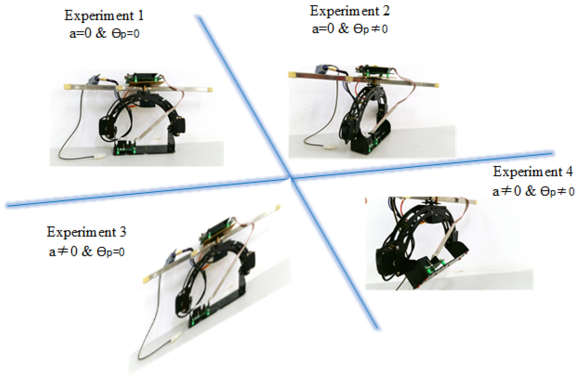
The experiment is divided into four groups. The experimental types are described by collecting and analyzing gyro signal data and accelerometer signal data under different motion states of stabilized platform. The detailed structures are shown in Figure 7. Angular output from gyro and angular output from the accelerometer are obtained. Angular variation is described by using the proposed accelerometer compensation method. Specifically, angular variation which uses the Kalman filtering method is described as auxiliary description. Kalman filtering is the recursive form of linear minimum variance estimation. The state equation and observation equation of the system can be decribed as follows [17].
where the actual angle and gyro constant deviation b are chosen as state vector . is observation from accelerometer. is angular velocity from gyro. Q and R are process noise and observation noise of the system. One-step state prediction is represented as follows.
The state at time k is predicted according to the state at time . Its covariance matrix is represented as follows.
Kalman gain is represented as follows.
The state estation is described as follows.
The state covariance matrix is described as follows.
In the first experiment, there is no accelerating or decelerating motion and no pitch or swing motion in carrier. In the second experiment, there is no accelerating or decelerating motion, but there is pitch and swing motion in carrier. In the third experiment, there are short-term accelerating or decelerating motion, but no pitch and swing motion in carrier. In the fourth experiment, there have short-term accelerating or decelerating motion, and with pitch or swing motion in carrier.
4.2. Experimental Results
4.2.1. The First Experiment (No Accelerating/Decelerating Motion And No Pitch/Swing Motion in Carrier)
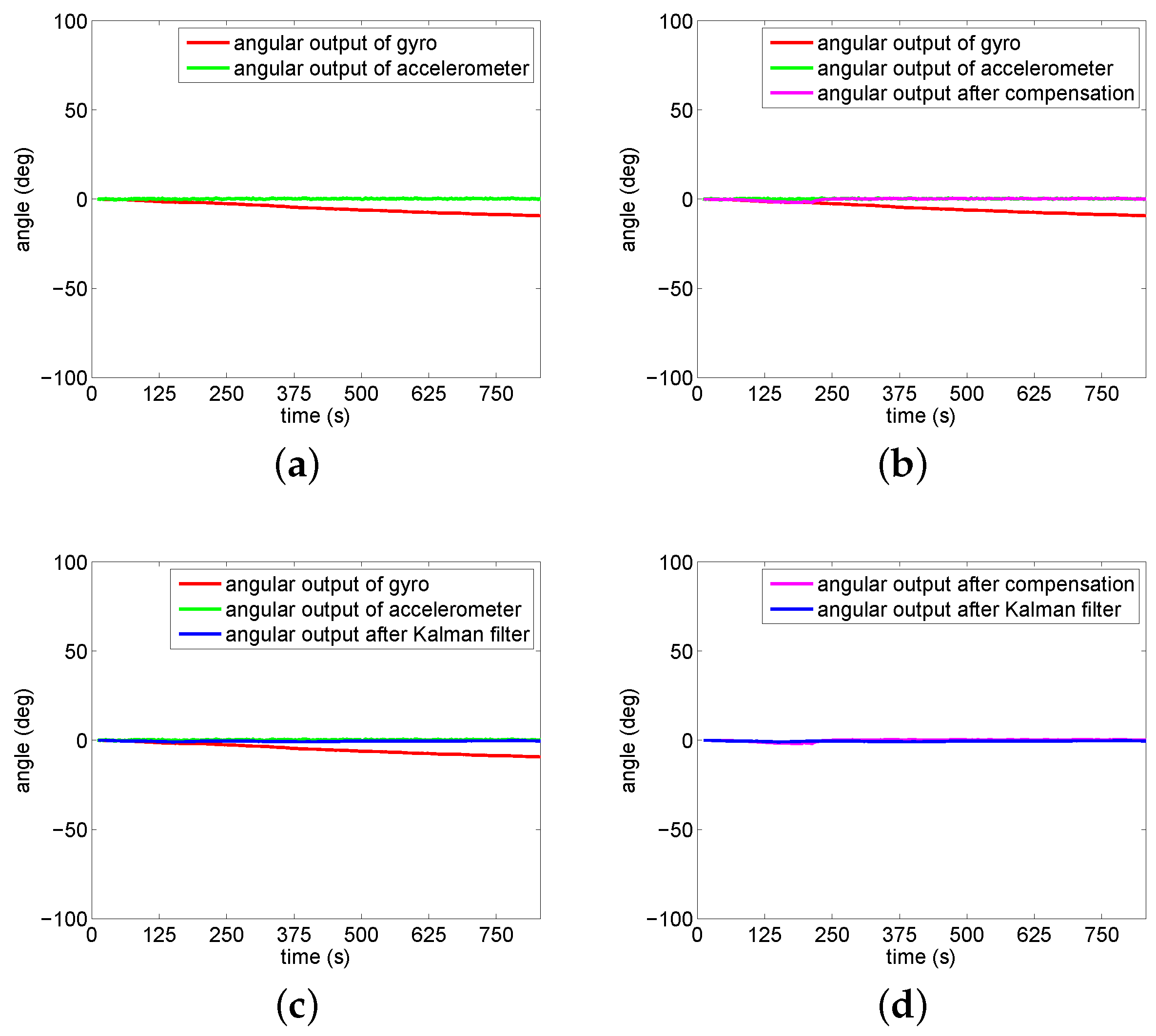
To clearly describe angular variation at different moments, different types of angular outputs are shown in Figure 8. It represents angular variation under the condition of no accelerating or decelerating motion and no pitch or swing motion in carrier.
Figure 8a shows angular outputs of gyro and accelerometer. There is an additional carmine line in Figure 8b, which represents angular output after applying the proposed compensation method. Figure 8c is similar with Figure 8b, but there is an additional blue line, which represents angular output after Kalman filter. Figure 8d shows angle outputs after applying the proposed compensation method and Kalman filtering method. It is observed that angle output gradually becomes zero after using the proposed compensation method and Kalman filtering method. That is to say, applying the proposed compensation method for gyro drift can achieve a similar effect that is comparable with the Kalman filtering method.
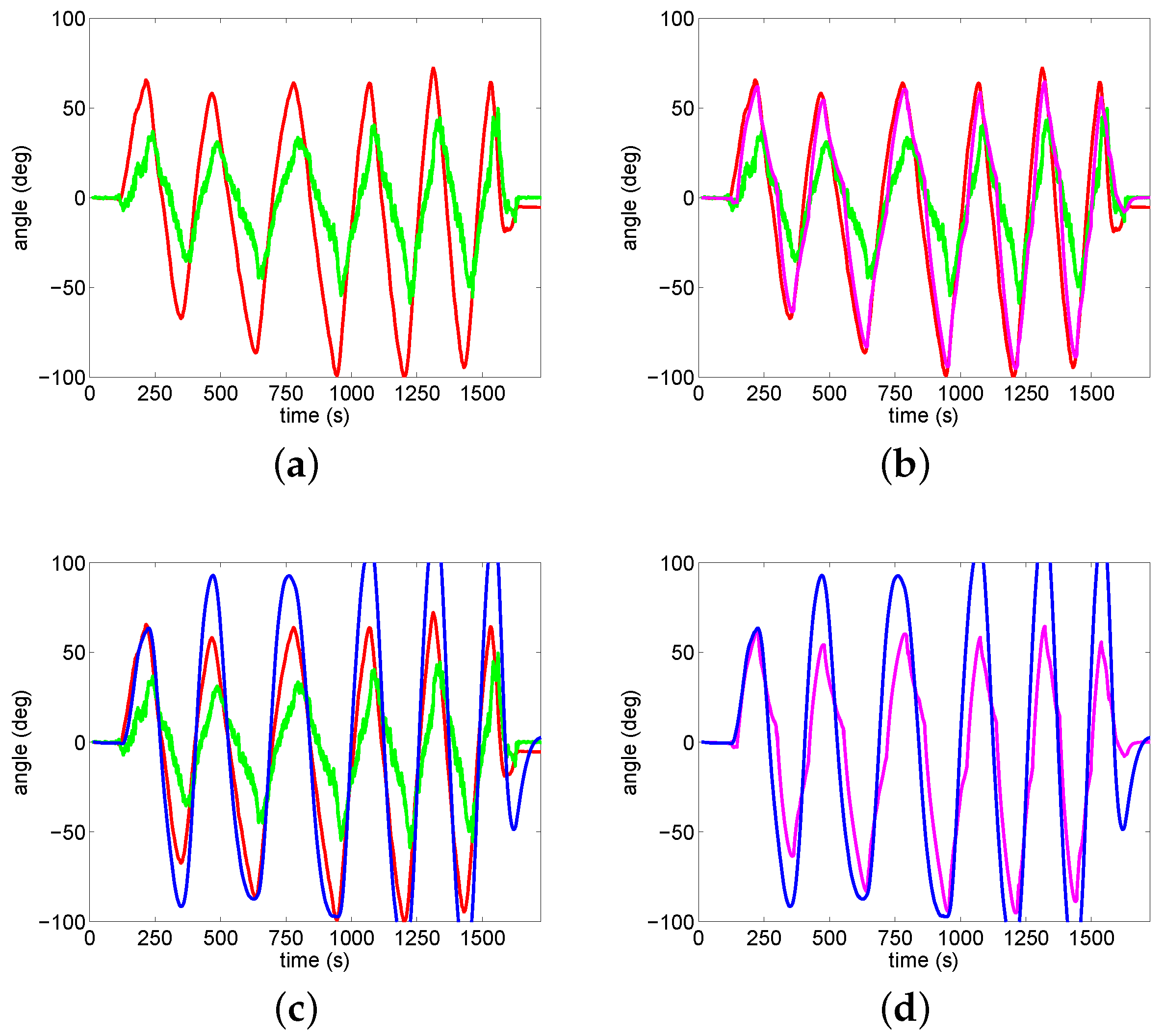
4.2.2. The Second Experiment (No Accelerating/Decelerating Motion But Have Pitch/Swing Motion in Carrier)
Figure 9 shows results of angle variation under the condition of no accelerating or decelerating motion and with pitch or swing motion in carrie. Figure 9b shows that angular output result is better after compensation. It also can be observed that angle changes become more smaller after using accelerometer compensation method than using Kalman filtering method in Figure 9d.
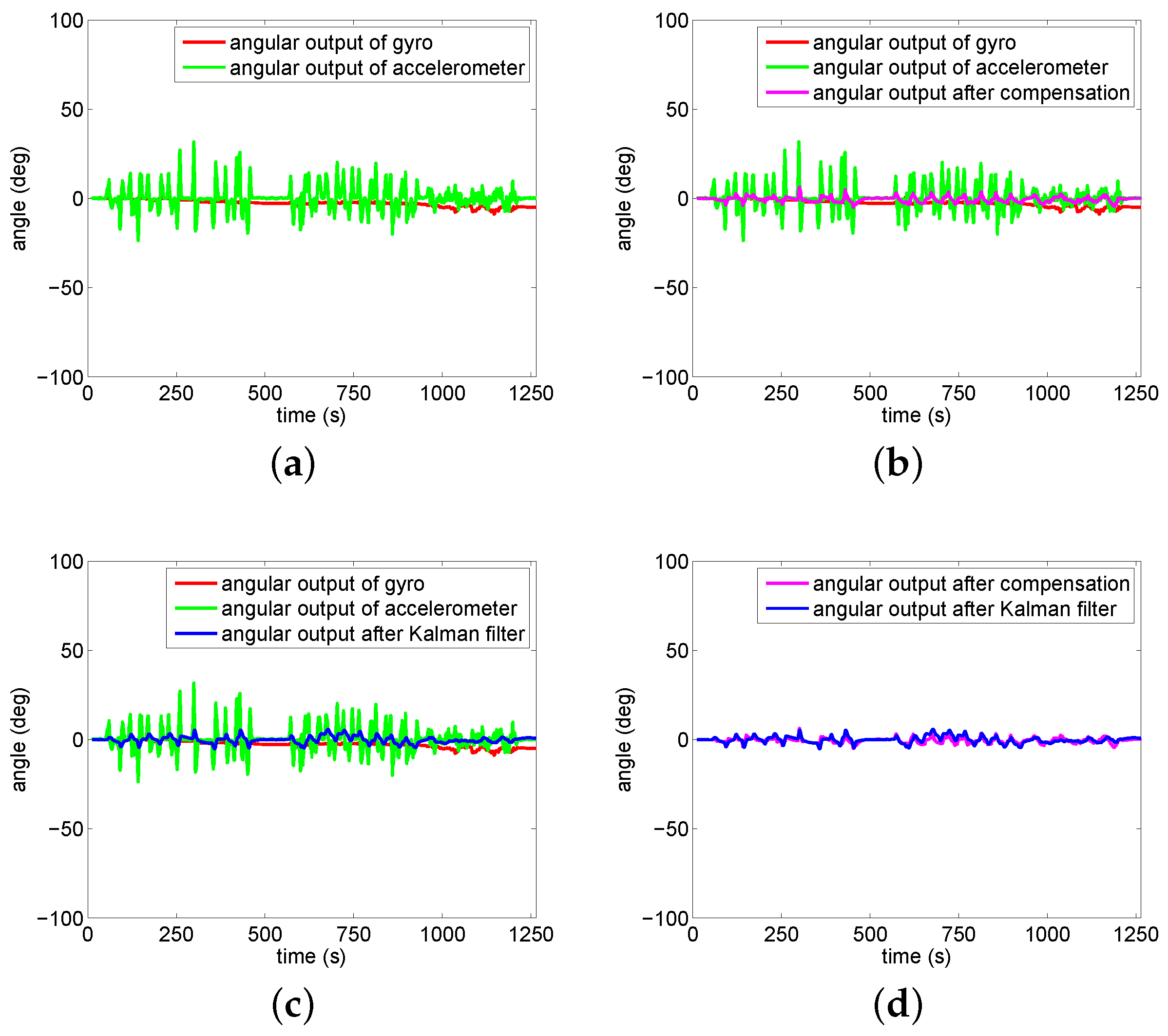
4.2.3. The Third Experiment (Has Short-Time Accelerating/Decelerating Motion but no Pitch/Swing Motion in Carrier)
4.2.4. The Fourth Experiment (Have Short-Time Accelerating/Decelerating Motion Have Pitch/Swing Motion in Carrier)
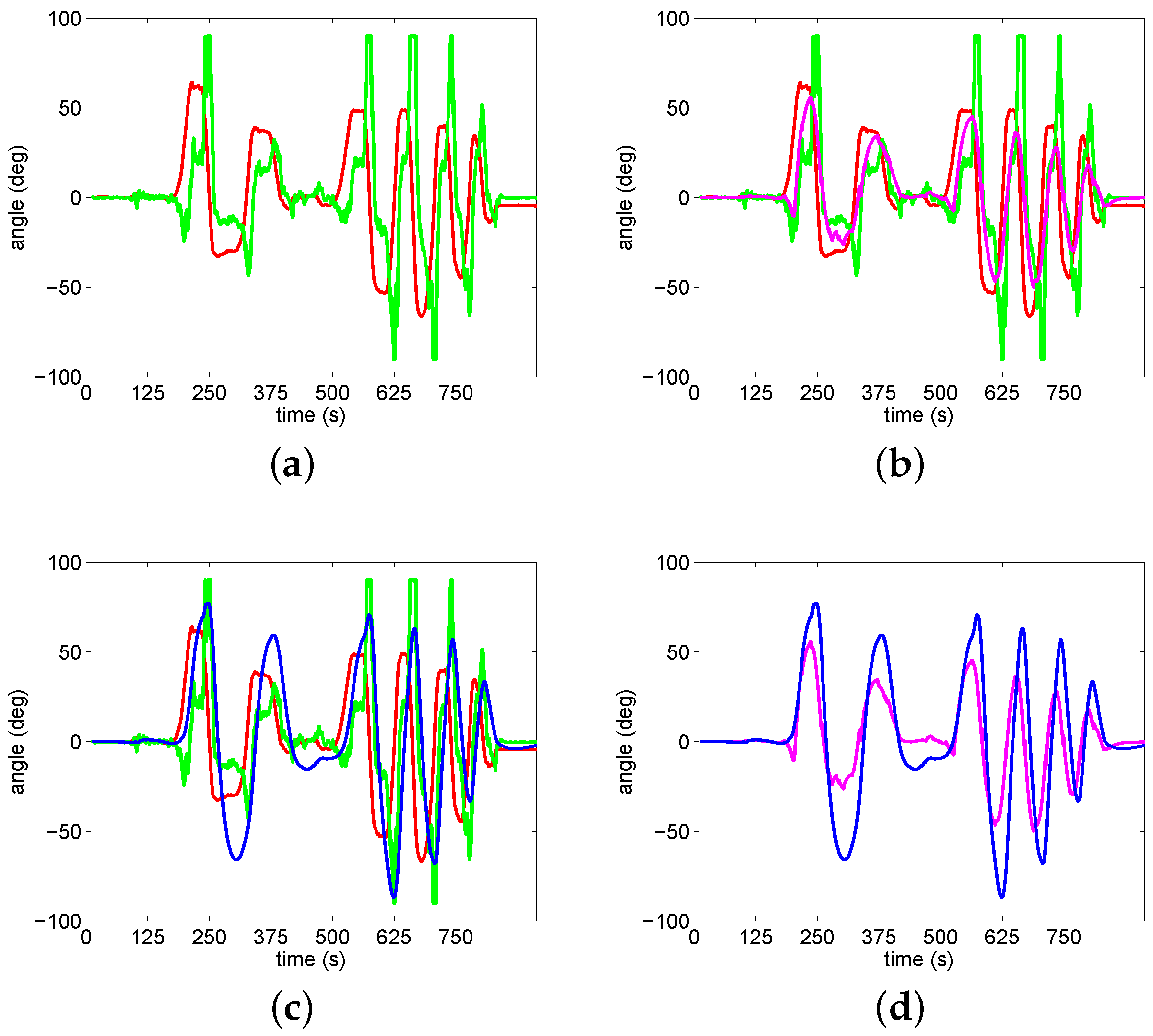
Figure 11 shows results of angle variation under the condition of short-time accelerating or decelerating motion and pitch or swing motion in carrie. It can be observed that angle changes are optimized after using accelerometer compensation method in Figure 11b. It can also be observed that angle changes are better after using an accelerometer compensation method than using Kalman filtering method in Figure 11d.
To further compare the performance of the proposed method and kalman filtering method, the performance index RSME (Root mean Squared Error) is adopted. Specifically, in order to compare the output values in detail, the maximum and minimum values of gyro angular outputs are calculated in four experiments. Maximum and minimum of accelerometer angular outputs are calculated in four experiments. Maximum and minimum values of angular outputs from the proposed compensate method and kalman filtering method are calculated and analyzed. Comparison resluts are shown in Table 1.
According to the above experiments, it is observed that angular output results are better after applying the proposed compensation method. Specifically, the angle value will increase with time when there is no compensation method for gyro drift.
5. Conclusions
A convenient gyro drift compensation method for a gyro-stabilized platform system by applying an accelerometer compensation strategy is proposed in this paper. This method is based on the high-precision characteristic of accelerometer. Simultaneously, data filtering algorithm and limit of threshold setting of total acceleration value are applied in this method. Motion equations of a stabilized platform are described and analyzed. The proposed method is simple and convenient compared with other compensation methods. Especially, in comparing with a complex compensation algorithm which needs long time, the proposed method needs shorter time. Compared with the kalman filtering method, this method provides an uncomplicated calculation. The efficiency and performance of the proposed compensation method are demonstrated by experiments. Future work will focus on applying the stabilized platform system to complete the real-time tracking task for the target.
Author Contributions
Conceptualization, S.L. and Y.G.; Methodology, S.L. and G.M.; Software, S.L. and G.M.; Validation, G.M.; Formal Analysis, S.L. and G.W.; Investigation, Y.G. and G.W.; Data Curation, S.L. and G.M.; Writing—Original Draft Preparation, S.L.; Visualization, L.G. and G.W.; Supervision, Y.G.; Project Administration, Y.G. and L.G.; Funding Acquisition, Y.G. and L.G.
Funding
This research was partially supported by the National Natural Science Foundation of China (No. 61803118), partially supported by the Science and Technology Research Program of Chongqing Municipal Education Commission (No. KJZD-K201804701), partially supported by the Post Doc. Foundation of Heilongjiang Province (No. LBH-Z17053) and partially supported by the Fundamental Research Funds for the Central Universities (No. HEUCFJ180402).
Conflicts of Interest
The authors declare no conflict of interest.
References
- Barshan, B.; DurrantWhyte, H.F. Inertial navigation systems for mobile robots. IEEE Trans. Robot. Autom. 1995, 11, 328–342. [Google Scholar] [CrossRef] [Green Version]
- Li, S.S.; Zhong, M.Y.; Yan, Z. Accelerometer error estimation and compensation for three-axis gyro-stabilized camera mount based on proportional multiple-integral observer. Sci. China Technol. Sci. 2014, 57, 2387–2395. [Google Scholar] [CrossRef]
- Luo, Y.; Ren, W.; Huang, Y.; He, Q.; Wu, Q.; Zhou, X.; Mao, Y. Feedforward Control Based on Error and Disturbance Observation for the CCD and Fiber-Optic Gyroscope-Based Mobile Optoelectronic Tracking System. Electronics 2018, 7, 223. [Google Scholar] [CrossRef]
- Xiao, Y.W.; Xiu, Y.M. Research on Time-series Modeling and Filtering Methods for MEMS Gyroscope Random Drift Error. In Proceedings of the IOP Conference Series: Materials Science and Engineering, Hong Kong, China, 28–30 December 2016; pp. 1–7. [Google Scholar] [CrossRef]
- Jiang, C.H.; Chen, Y.W.; Chen, S.; Bo, Y.; Li, W.; Tian, W.; Guo, J. A Mixed Deep Recurrent Neural Network for MEMS Gyroscope Noise Suppressing. Electronics 2019, 8, 181. [Google Scholar] [CrossRef]
- Krogh, M.R.; Nghiem, M.G.; Halvorsen, P.S.; Elle, O.J.; Grymyr, O.J.; Hoff, L.; Remme, E.W. Gravity Compensation Method for Combined Accelerometer and Gyro Sensors Used in Cardiac Motion Measurements. Ann. Biomed. Eng. 2017, 45, 1–13. [Google Scholar] [CrossRef] [PubMed]
- Giansanti, D.; Maccioni, G.; Macellari, V. Guidlines for Calibration and Drift Compensation of a Wearable Device with Rate-Gyroscopes and Accelerometers. In Proceedings of the 29th Annual International Conference of the IEEE Engineering in Medicine and Biology Society, Lyon, France, 22–26 August 2007; pp. 2342–2345. [Google Scholar] [CrossRef]
- Wu, H.; Zwirello, L.; Li, X.; Reichardt, L.; Zwick, T. Motion compensation with one-axis gyroscope and two-axis accelerometer for automotive SAR. In Proceedings of the 2011 German Microwave Conference, Darmstadt, Germany, 14–16 March 2011; pp. 1–4. [Google Scholar]
- Priel, B. The effect of gyro nonorthogonality error on gyrocompassing. IEEE Trans. Aerosp. Electr. Syst. 1992, 28, 890–893. [Google Scholar] [CrossRef]
- Lee, H.; Jung, S. Gyro sensor drift compensation by Kalman filter to control a mobile inverted pendulum robot system. In Proceedings of the 2009 IEEE International Conference on Industrial Technology, Gippsland, VIC, Australia, 10–13 February 2009; pp. 1–6. [Google Scholar] [CrossRef]
- Shi, Z.; Yang, J.; Yue, P.; Cheng, Z. A new calibration and compensation method for installation errors of accelerometers in Gyroscope Free Strap-down Inertial Navigation System. In Proceedings of the 2010 IEEE International Conference on Information and Automation, Harbin, China, 20–23 June 2010; pp. 924–929. [Google Scholar] [CrossRef]
- Ghanbari, M.; Yazdanpanah, M.J. Delay Compensation of Tilt Sensors Based on MEMS Accelerometer Using Data Fusion Technique. IEEE Sens. J. 2015, 15, 1959–1966. [Google Scholar] [CrossRef]
- Hsu, Y.L.; Chou, P.H.; Kuo, Y.C. Drift modeling and compensation for MEMS-based gyroscope using a Wiener-type recurrent neural network. In Proceedings of the 2017 IEEE International Symposium on Inertial Sensors and Systems (INERTIAL), Kauai, HI, USA, 27–30 March 2017; pp. 39–42. [Google Scholar] [CrossRef]
- Luo, H.; Fan, D.P.; Zhang, Z.Y.; Wu, Z.H. Several issues in installation of 2-axis rate gyro stabilized sighting system. Acta Armamentarii 2005, 3, 426–428. [Google Scholar]
- Ahmed, H.; Tahir, M. Accurate Attitude Estimation of a Moving Land Vehicle Using Low-Cost MEMS IMU Sensors. IEEE Trans. Intell. Transp. Syst. 2017, 18, 1723–1739. [Google Scholar] [CrossRef]
- Xiong, L.; Xia, X.; Lu, Y.; Liu, W.; Gao, L.; Song, S.; Han, Y.; Yu, Z. IMU-Based Automated Vehicle Slip Angle and Attitude Estimation Aided by Vehicle Dynamics. Sensors 2019, 19, 1930. [Google Scholar] [CrossRef] [PubMed]
- Xu, C.; Ji, M.M.; Qi, Y.; Zhou, X.H. MCC-CKF: A Distance Constrained Kalman Filter Method for Indoor TOA Localization Applications. Electronics 2019, 8, 478. [Google Scholar] [CrossRef]
Figure 1.
Coordinate system of two-axis stabilized platform.

Figure 2.
Relation between carrier coordinate with heading coordinate.

Figure 3.
Relation between pitch coordinate with heading coordinate.

Figure 4.
Accelerometer compensation algorithm.

Figure 5.
Tri-Axis inertial sensor.

Figure 6.
Stabilized platform structure.

Figure 7.
Experimental schemes.

Figure 8.
Experiment 1 (Red line is angular output of gyro. Green line is angular output of accelerometer. Carmine line is angular output after compensation. Blue line is angular output after Kalman filter.). (a) Angular outputs of gyro/accelerometer; (b) Applying the proposed compensation method; (c) Applying Kalman filtering method; (d) Comparison of two methods.

Figure 9.
Experiment 2 (Red line is angular output of gyro. Green line is angular output of accelerometer. Carmine line is angular output after compensation. Blue line is angular output after Kalman filter.). (a) Angular outputs of gyro/accelerometer; (b) Applying the proposed compensation method; (c) Applying Kalman filtering method; (d) Comparison of two methods.

Figure 10.
Experiment 3 (Red line is angular output of gyro. Green line is angular output of accelerometer. Carmine line is angular output after compensation. Blue line is angular output after Kalman filter.). (a) Angular outputs of gyro/accelerometer; (b) Applying the proposed compensation method; (c) Applying Kalman filtering method; (d) Comparison of two methods.

Figure 11.
Experiment 4 (Red line is angular output of gyro. Green line is angular output of accelerometer. Carmine line is angular output after compensation. Blue line is angular output after Kalman filter.). (a) Angular outputs of gyro/accelerometer; (b) Applying the proposed compensation method; (c) Applying Kalman filtering method; (d) Comparison of two methods.


Table 1.
Comparison values of different model output.
| Variables () | ||||||
|---|---|---|---|---|---|---|
| Test | Gyro Output | Accelerometer Output | Compensate Output | Kalman Filtering Output | RMSE | |
| 1 | Maximum | 0.0121 | 0.0768 | 0.0121 | 0.0018 | 0.7129 |
| Minimum | −9.3479 | −0.6044 | −9.3479 | −0.8931 | ||
| 2 | Maximum | 72.2037 | 49.6233 | 64.5023 | 128.0119 | 36.2793 |
| Minimum | −99.7089 | −58.7377 | −95.1445 | −125.7425 | ||
| 3 | Maximum | 1.1440 | 31.7862 | 6.2761 | 5.7730 | 1.4792 |
| Minimum | −8.7321 | −23.5145 | −5.0088 | −5.1348 | ||
| 4 | Maximum | 64.2018 | 90 | 55.7620 | 76.8738 | 22.5706 |
| Minimum | −66.5831 | −90 | −49.8283 | −86.9542 |
© 2019 by the authors. Licensee MDPI, Basel, Switzerland. This article is an open access article distributed under the terms and conditions of the Creative Commons Attribution (CC BY) license (http://creativecommons.org/licenses/by/4.0/).
Share and Cite
MDPI and ACS Style
Li, S.; Gao, Y.; Meng, G.; Wang, G.; Guan, L. Accelerometer-Based Gyroscope Drift Compensation Approach in a Dual-Axial Stabilization Platform. Electronics 2019, 8, 594. https://doi.org/10.3390/electronics8050594
AMA Style
Li S, Gao Y, Meng G, Wang G, Guan L. Accelerometer-Based Gyroscope Drift Compensation Approach in a Dual-Axial Stabilization Platform. Electronics. 2019; 8(5):594. https://doi.org/10.3390/electronics8050594
Chicago/Turabian StyleLi, Shutong, Yanbin Gao, Gong Meng, Gang Wang, and Lianwu Guan. 2019. "Accelerometer-Based Gyroscope Drift Compensation Approach in a Dual-Axial Stabilization Platform" Electronics 8, no. 5: 594. https://doi.org/10.3390/electronics8050594
Note that from the first issue of 2016, this journal uses article numbers instead of page numbers. See further details here.