Four-State Coupled-Line Resonator for Chipless RFID Tags Application


Department of Electrical Engineering, King Saud University, Riyadh 11421, Saudi Arabia
*
Author to whom correspondence should be addressed.
Electronics 2019, 8(5), 581; https://doi.org/10.3390/electronics8050581
Submission received: 29 April 2019
/
Accepted: 23 May 2019
/
Published: 25 May 2019
(This article belongs to the Section Microwave and Wireless Communications)
Abstract
:A novel quad-state coupled-line microstrip resonator is proposed for compact chipless radio frequency identification (RFID) tags. The proposed resonator can be reconfigured to present one of four possible states: 00, 01, 10, and 11, representing, no resonance, resonance at f2, resonance at f1, and resonance at both f1 and f2, respectively. The frequency span between f2 and f1 can be easily controlled, thereby reducing the required spectrum. Moreover, the proposed technique allows the storage of a large amount of data in a compact size to reduce the cost per bit. A multi-resonator prototype consisting of six resonators is designed, analyzed, and experimentally characterized. This prototype is implemented on the RT Duroid 5880 substrate with a dielectric constant of 2.2, loss tangent of 0.0009, and thickness of 0.79 mm. The designed configuration can be reconfigured for 46 codes. Two complete the RFID tags, including the six resonators and two orthogonally polarized transmitting and receiving antennas, are implemented and tested. The first tag code is designed for all ones, 111111111111, and the second tag is designed as 101010101010 code. Experimental results show good agreement with the simulation.
1. Introduction
In a radio frequency identification (RFID) system, radio frequency waves are used to read identification codes implemented on a tag. The main components of an RFID system include: An RFID transponder (a tag containing a sequence of electronic codes used for object identification), and an RFID reader (an interrogator that collects information from the tag) [1]. However, low-cost applications are still dominated by traditional barcodes rather than RFID tags, owing to the high prices of the latter [2]. Therefore, chipless RFID tags have recently attracted attention as a promising candidate to replace barcodes. The size and capacity of chipless RFID tags are among the main challenges for their cost reduction and thus wide adoption.
Different methods are reported in the literature for data encoding in chipless RFID tags. Generally, these encoding techniques can be classified into various domains, such as time, frequency, phase, and hybrid-domains [3]. In time-domain-based systems [4,5], the RFID reader interrogates the tag with a sequence of short pulses. Subsequently, the tag receives the interrogating pulses and then retransmits the response signal as a train of echoes with some time delays. The presence or absence of echoes and their position along the time axis are used to read out the tag ID. The surface acoustic wave (SAW) chipless RFID tag is the most popular and commercial time-domain-based chipless tag [6]. However, these tags are not recommended for cost-effective applications, owing to the high material costs and complex fabrication process. In frequency-based chipless RFID systems [7,8], the reader interrogates the tag with an electromagnetic (EM) waveform and then the tag retransmits (or backscatters) the response to the RFID reader. In the phase domain, differences in the phase profile are used to encode the bits [9,10]. In hybrid-domain encoding techniques, more than one domain is used. These additional domains include phase–frequency [11,12], time–frequency [13], impedance loading [14], polarization–phase [15], and frequency–position [16]. However, as mentioned in [17], for a significant number of bits, hybrid-domain techniques still require a very high spectral bandwidth and the resultant configuration in this case will not be matched for low-cost readers.
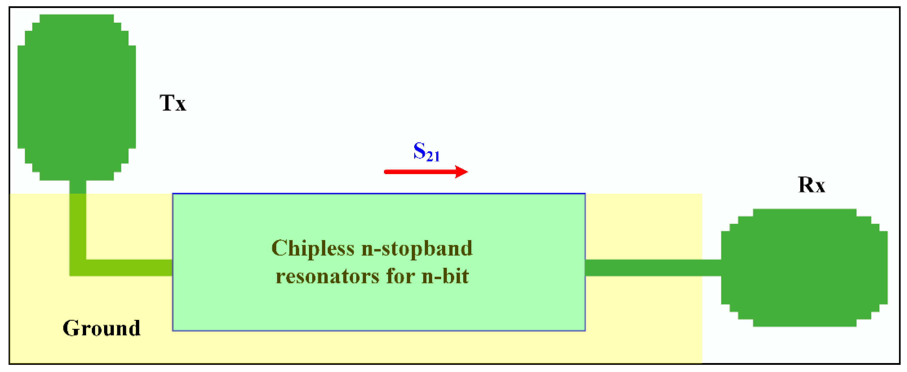
Returning to frequency-domain chipless RFID systems, there are two different types of tags: Backscattering-based and retransmission-based. In the backscattering technique, the tag contains only resonating elements, where no separate antennas are required [18,19]. More advantages of this technique include the tag’s small size and easier readability. However, adding more bits introduces coupling and affects the resonance frequency of the other units, and more calibration may be required to overcome this influence [20]. As shown in Figure 1, a retransmission-based chipless RFID tag consists of orthogonally polarized transmitting and receiving antennas and a sequence of n resonators (for an n-bit tag), in which the information is stored [1,21]. The presence or absence of a resonance is encoded as 1 (at which S21 < −10 dB) or 0, respectively. The resonators are always implemented with a microstrip structure; hence, its ground acts to minimize the effect of the object to which the tag is attached. In addition, this technique has a more stable performance because the use of two orthogonally polarized antennas significantly reduces the interference between the transmitted and received waves [20]. Moreover, the tag capacity can be increased by simply adding more resonators to the structure and the arising mutual coupling can be reduced by adjusting the distance between the resonators. Retransmission chipless RFID tags are based on stopband resonators. Stopband characteristics in the microstrip technique can be achieved by either directly connecting quarter-wave stubs to the feeder line [22,23,24,25], or by a short-circuited quarter-wave coupled line, as shown in Figure 2. The short circuit shown in Figure 2 can be replaced by another quarter-wave open-circuit stub to produce various forms of tags. Several chipless RFID tags have been developed based on these types of resonators, such as spiral resonators [26,27,28,29,30], open-loop resonators [31], L-strip shaped resonators [32], and complementary split-ring resonators (CSRR) [33]. An improved structure that combines a spiral and T-shaped coupled line in a compact form is proposed in [34]. Each resonator in these configurations is represented by only one bit; hence, an n-bit tag requires n resonators and produces 2n codes.
In this paper, a new coupled-line microstrip resonator is proposed for compact high-capacity chipless RFID tags. Each resonator can store either 00 (no frequency response), 01 (resonance at f2), 10 (resonance at f1), or 11 (resonance at both f1 and f2). The frequency span between f2 and f1 can be easily controlled, thereby reducing the required spectrum. In other words, every resonator of the proposed tag can encode two bits. The proposed technique allows the storage of a large amount of data in a compact size to reduce the cost per bit. The prototype consisted of six microstrip resonators designed and fabricated on the RT Duroid 5880 substrate , , and ). The information of each resonator can be stored in two frequencies f1 and f2. The implemented tag prototype can be reconfigured for 46 codes and 12 possible frequencies. The prototype was fabricated and the results were validated. The measured results were found to be in good agreement with the simulations. The remainder of this paper is organized as follows. Section 2 discusses the basic operation of the proposed resonator. The analysis and design of the six resonators of the suggested structure are explained in Section 3. Three different codes are also designed and experimentally validated. The design and testing of a complete RFID tag based on the proposed structure are discussed in Section 4. Finally, conclusions are drawn in Section 5.
2. Two-Bit Coupled-Line Stopband Resonator
The schematic diagram and equivalent circuit of the proposed coupled-line resonator are shown in Figure 2. This coupled-line resonator can be analyzed in the manner suggested by Jones and Bolljahn [35]. The stopband characteristics of this resonator can be explained in terms of image impedances ZI1 and ZI2.
The image impedances of the coupled line shown in Figure 2 at ports 1 and 2 are given by the following:
where θ is the coupled line electrical length, and Zoe and Zoo are the characteristic impedances of the even and odd mode, respectively. These equations show that the fundamental stopband resonance occurs when θ = π/2, that is, when the coupled line length is equal to one quarter-wavelength at the fundamental resonance frequency f0. This structure also produces stopband characteristics at all odd harmonics.
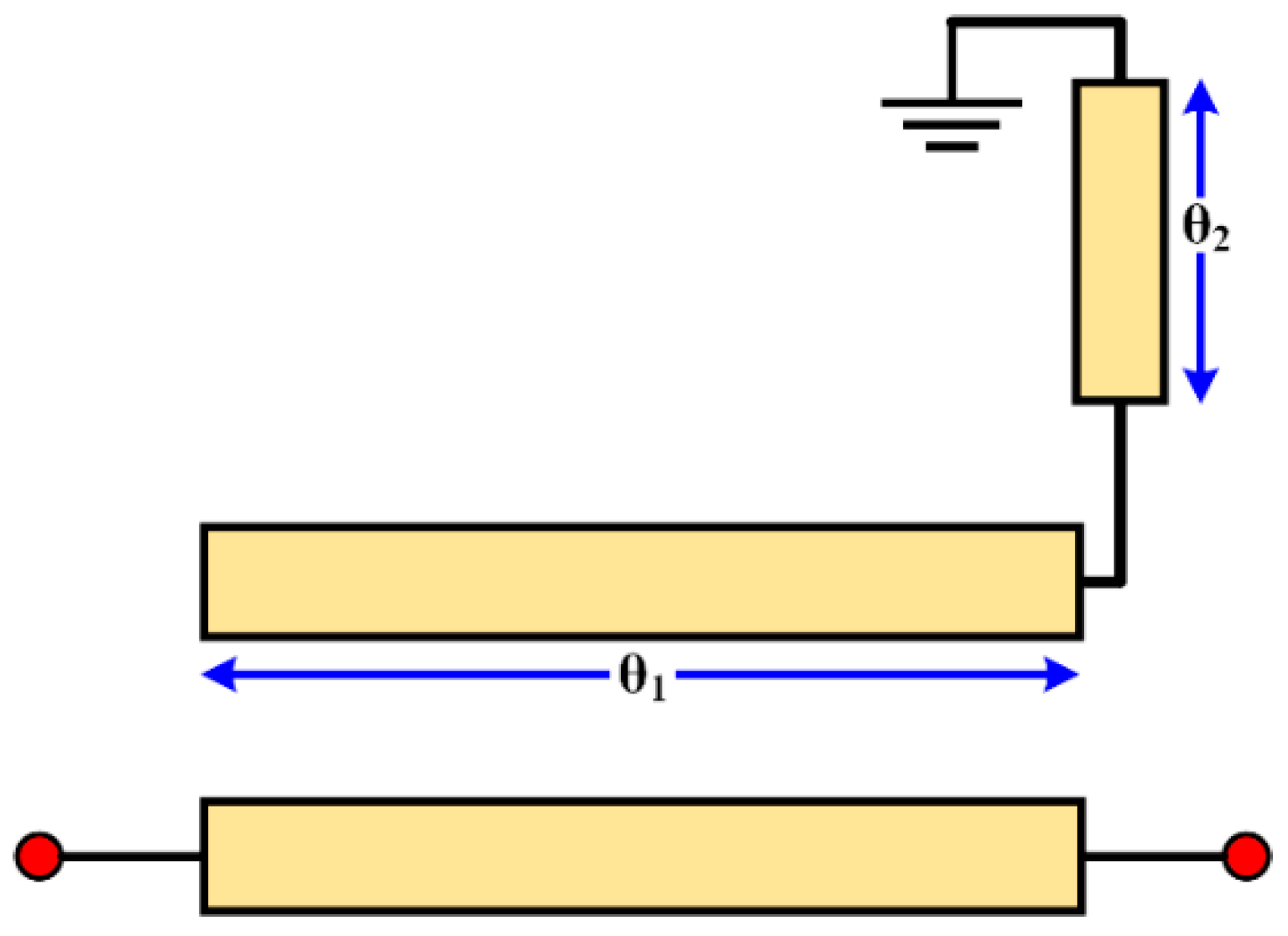
For the purpose of compactness, or any other appropriate layout arrangements, the quarter-wavelength line can be bent (as shown in Figure 3) without losing the stopband behavior, apart from a slight shift in the resonance frequency. If the electrical length of the coupled line section is denoted as θ1 and the electrical length of the vertical line is θ2, then the total electric length is θ = θ1 + θ2. At the fundamental resonance frequency, very little decrease in the total electrical length is noticed. As an example, θ changes from 90° to 85° when θ1 decreases from 90° to 30°. However, the bandwidth of the resonator decreases as θ1 decreases.
For cost-effective chipless RFID, the short circuit is usually replaced by an open-circuit quarter-wavelength stub at f0. In this case, the fundamental resonance frequency remains unchanged at f0. However, the first harmonic appears at approximately 2f0.
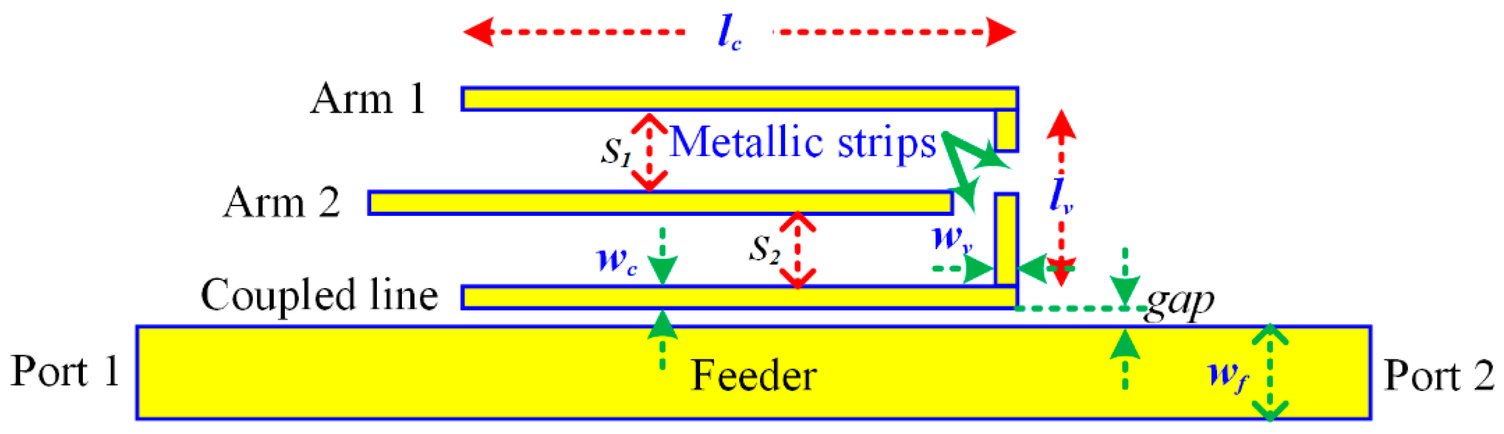
In our design, the short circuit in Figure 3 can be replaced by a quarter-wavelength open-circuit stub at f1 or f2, where f1 and f2 are close to each other. For a proof of concept, the proposed resonator shown in Figure 4 is designed to have f1 and f2 at 5 and 5.2 GHz, respectively. The circuit was designed on the Duroid substrate of a dielectric constant 2.2 and thickness 0.78 mm. The physical parameters of the circuit shown in Figure 4 are given in Table 1. This coupled line of length lc and width wc can be connected to arm 1, arm 2, or both arms using short metallic strips through a vertical arm of length lv and width wv. This resonator can be reconfigured in order to present a quad-state.
The various types of states can be obtained using the connections shown in Figure 5. The first state, S1-state, is achieved when arms 1 and 2 are not connected to the vertical line. No resonance can be observed in the band of operation, and this case is represented by the code 00. If only arm 2 is connected to the vertical line by a short metallic strip, the resonator resonance frequency in this case is f2 and the resonator is represented by the code 01 as shown in Figure 5b (S2-state). The third case, S3-state, is when only arm 1 is connected to the vertical line by a short metallic strip. The resonance frequency is f1 and this state is represented by the code 10. In the fourth sate, S4-state, both arms are connected to the vertical coupled line. Therefore, the resonance occurs at f1 and f2 and the resonator is represented by the code 11. These four possible states are summarized in Table 2.
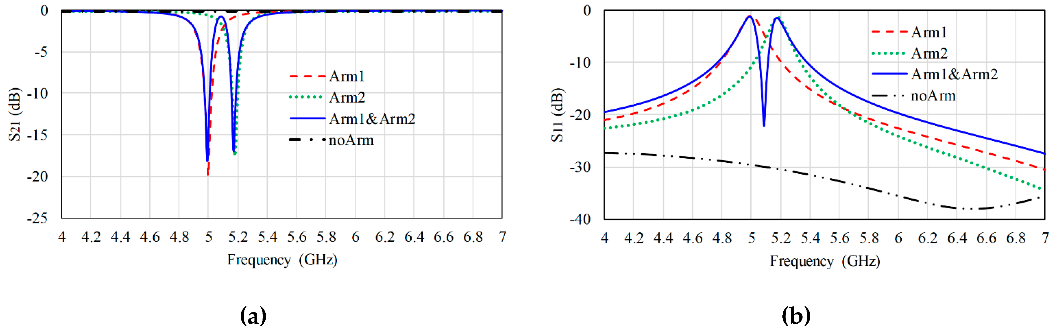
Figure 6 shows the simulated insertion and return losses of a single quad-state microstrip resonator in four possible states “00,” “01,” “10,” and “11.” From this graph, there are two distinct resonant dip nulls in the magnitude of S21 (f1 and f2). Additionally, there are two peaks in the magnitude of S11, which can be also used to identify the null location. The existence of a null in the insertion loss represents logic “1,” whereas the absence of the null represents logic “0.”
3. Multi-Resonator Structure Design and Analysis
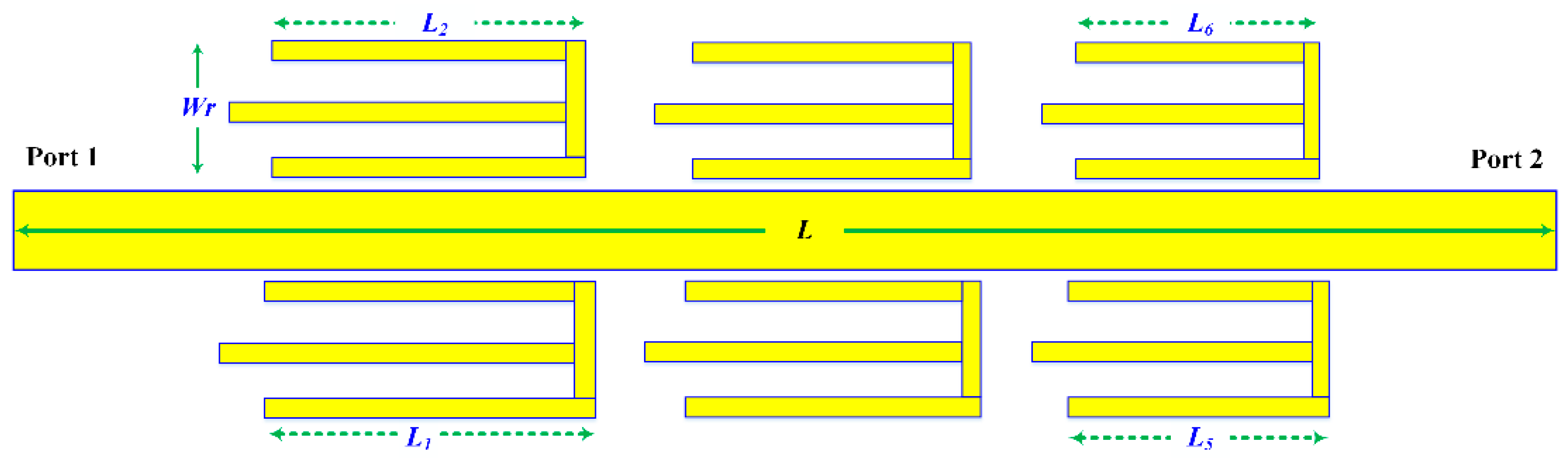
A six-resonator circuit based on the proposed resonator discussed in the previous section was developed on the Duroid substrate of a dielectric constant 2.2 and thickness 0.78 mm. The CST Microwave Studio was used to design and simulate the proposed tag. This structure was designed to maintain the frequency span for each resonator at approximately 200 MHz. The frequency span between each two adjacent resonators was also chosen to be approximately 200 MHz. The structure layout is shown in Figure 7. For the operation from 5.4 to 8 GHz, the resonator lengths were selected from L1 = 9.4 mm to L6 = 5.5 mm. The separation between the adjacent resonators was 1 mm. The feeder width was designed for a characteristic impedance of 50 Ω, which resulted in a width of 2.4 mm for the chosen substrate. The total length and width of the structure was 29.4 and 12.6 mm, respectively.
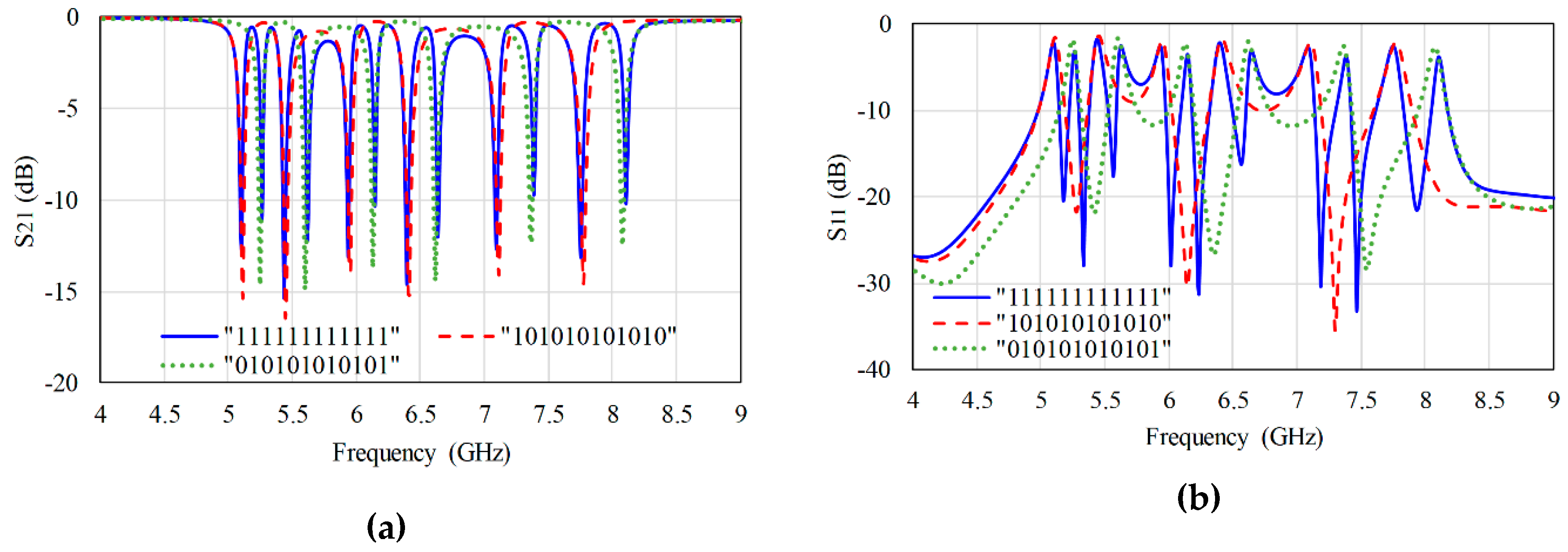
Four configurations were developed to validate the concept. The first structure is shown in Figure 7, where all the resonators are connected to represent the code 11 for each one. Therefore, the configuration code is 111111111111. The second configuration represents all zeros, where the two arms of all resonators are not connected. The third configuration represents code 101010101010, and obtained with arms 1 of all the resonators connected and arms 2 not connected. The fourth configuration represents 010101010101, and consists of arms 2 of all the resonators connected and arms 1 not connected. The simulation results of S21 and S11 of the first two codes are shown in Figure 8. The simulation results of the first, third, and fourth codes are shown in Figure 9. It must be noted from this figure that almost no frequency shift was noticed when switching any resonator from one code to another. Many other codes, not presented in this paper, such as 011110011110, 110011001100, and 001100110011, were designed and verified.
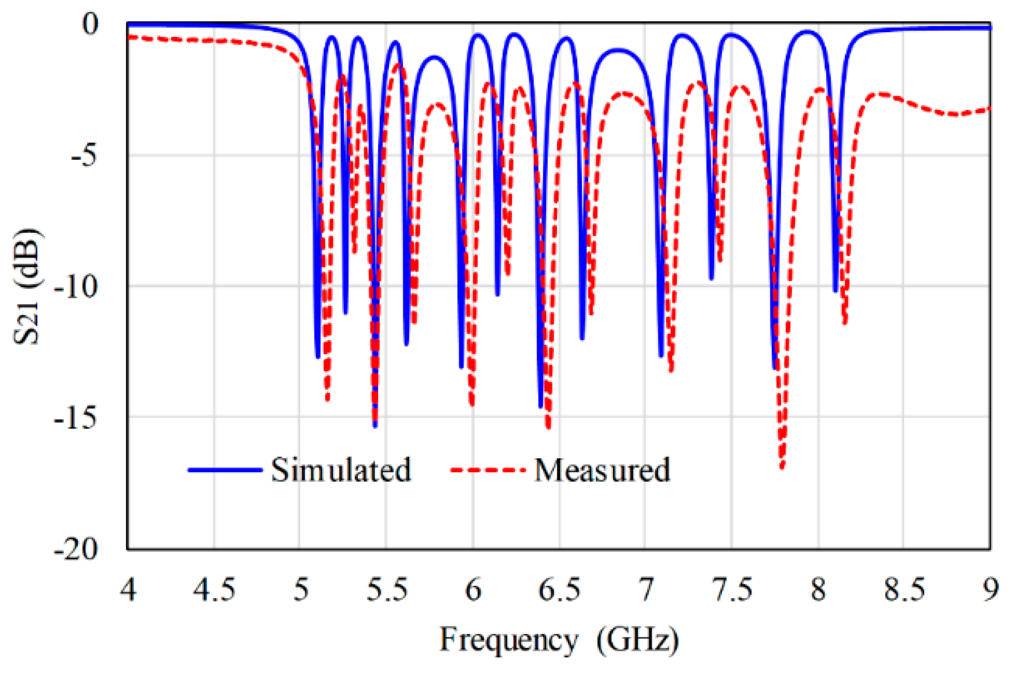
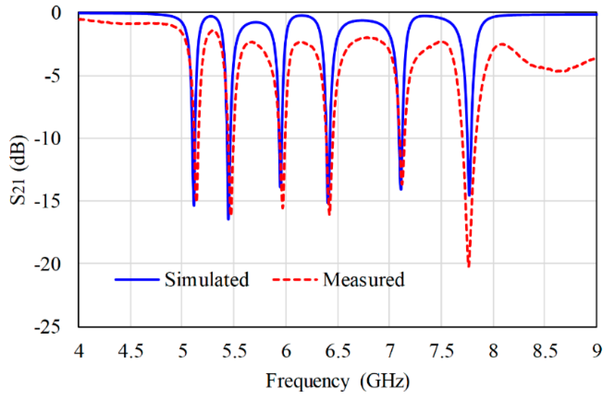
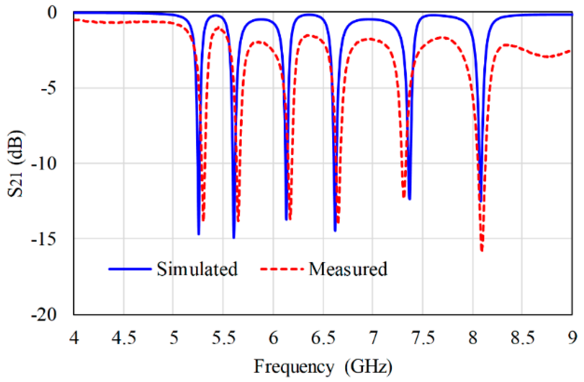
The three codes 111111111111, 101010101010, and 010101010101 were implemented and their photographs are shown in Figure 10. The measured and simulated S21 were compared as shown in Figure 11, Figure 12 and Figure 13. Only very small shifts to higher frequency were noticed in the measurements.
This may be attributed to the fabrication accuracy or high tolerance in the substrate parameters. The measurements were performed on an Anritsu Vector Network Analyzer (VNA 37369C), and showed good agreement with the simulations.
4. Integrated Chipless RFID Tag Prototype
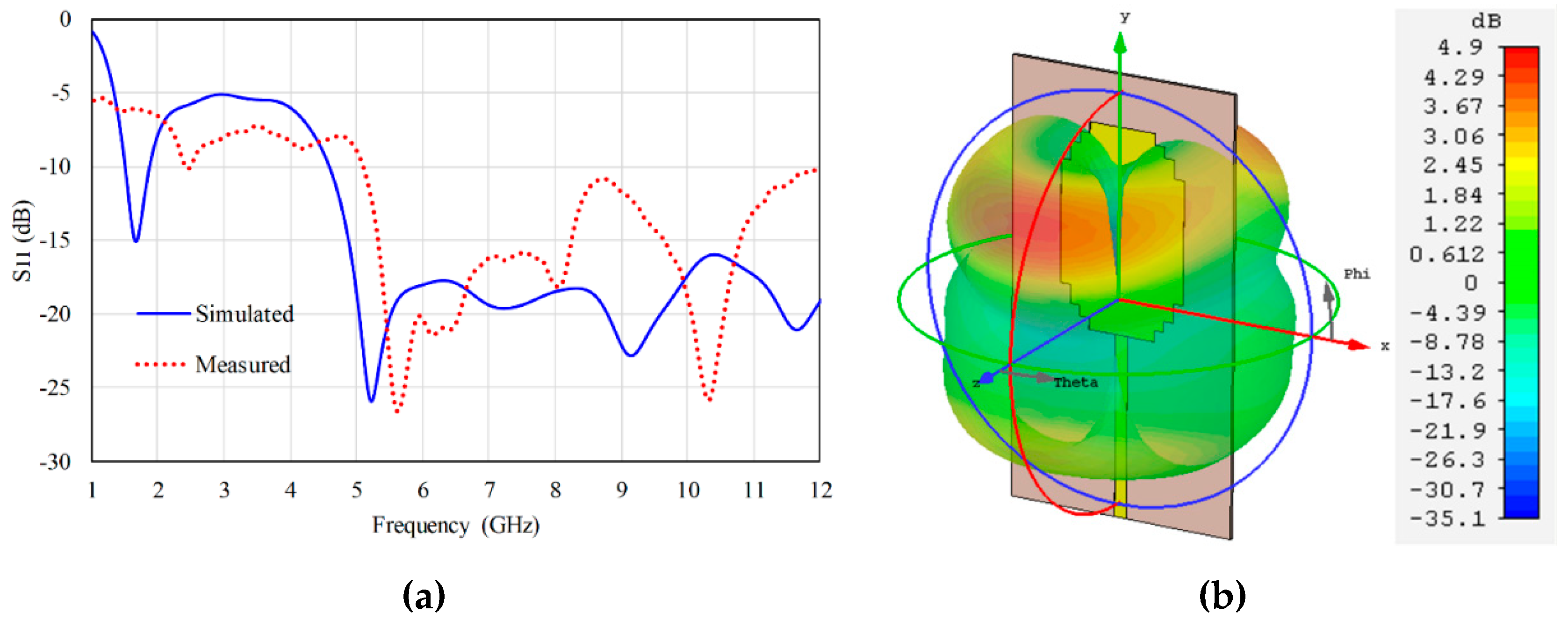
Two typical wideband monopole antennas covering the frequency range from 5 to 10 GHz were designed and optimized to verify the proposed tag experimentally. The antenna is shown in Figure 14, and its parameters are listed in Table 3. Figure 15a shows the simulated and measured return loss. The measured bandwidth for S11 < −10 dB was extended from GHz to 12 GHz. In addition, the 3D radiation pattern at 7 GHz is displayed in Figure 15b.
The two antennas were connected to opposite ends of the feeder line of the six-resonator structures implemented in the previous section. The two antennas were placed in an orthogonal-polarization arrangement, as shown in Figure 16.
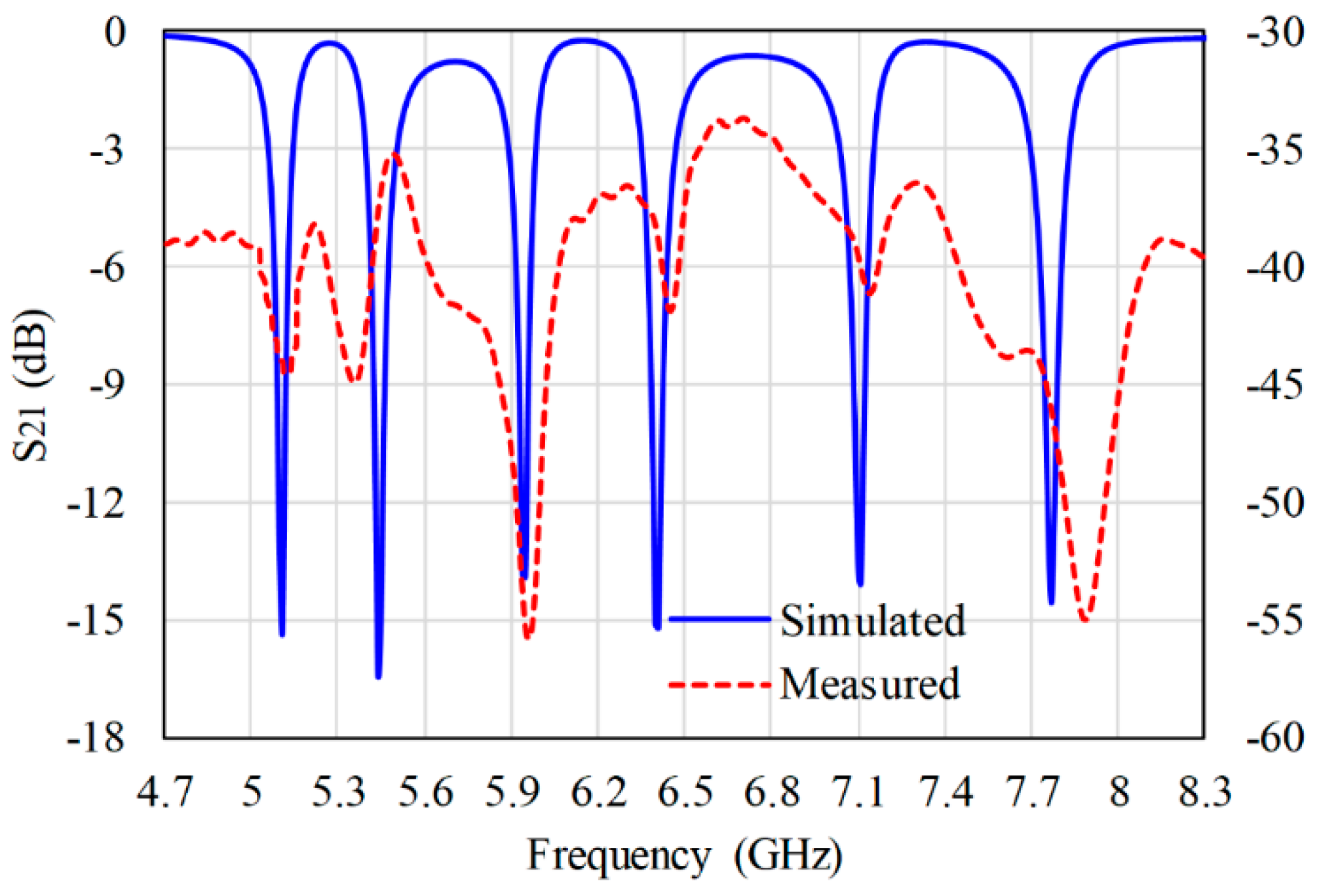
A measurement setup was established to validate the proposed chipless RFID tag system, as shown in Figure 17. The test was performed in an anechoic chamber, and two different six-resonator tag codes were used. Tag (1) had code 111111111111, and tag (2) was 101010101010. The measured results of tag (1) and tag (2) are illustrated in Figure 18 and Figure 19, respectively. It can be seen from these figures that the measured and simulated results matched well, with slight shifts in certain resonance frequencies.
5. Conclusions
In this study, a novel and compact chipless RFID tag was designed and fabricated. This structure contains six quad-state microstrip coupled-line resonators. For each resonator, two resonance frequencies are possible; therefore, a single resonator can be reconfigured for two-bit information codes (00, 01, 10, and 11), which is more economical than conventional chipless RFID tag designs. The proposed tag can be reconfigured for 46 codes and 12 possible frequencies. The measured insertion loss is found to be in good agreement with the simulation.
Author Contributions
Conceptualization, W.M.A. and A.-F.A.S.; Methodology, W.M.A. and A.-F.A.S.; Software, W.M.A.; Validation, W.M.A. and A.-F.A.S.; Formal Analysis, W.M.A. and A.-F.A.S.; Investigation, A.-F.A.S.; Resources, A.-F.A.S.; Data Curation, W.M.A.; Writing—Original Draft Preparation, W.M.A.; Writing—Review and Editing, W.M.A. and A.-F.A.S.; Visualization, W.M.A. and A.-F.A.S.; Supervision, A.-F.A.S.
Funding
This research received no external funding.
Acknowledgments
The authors would like to thank Deanship of scientific research for funding and supporting this research through the initiative of DSR Graduate Students Research Support (GSR).
Conflicts of Interest
The authors declare no conflict of interest.
References
- Preradovic, S.; Karmakar, N.C. Chipless RFID: Bar code of the future. IEEE Microw. Mag. 2010, 11, 87–97. [Google Scholar]
- Islam, M.A.; Yap, Y.; Karmakar, N. ‘Δ’ slotted compact printable orientation insensitive chipless RFID tag for long range applications. In Proceedings of the 2016 9th International Conference on Electrical and Computer Engineering (ICECE), Dhaka, Bangladesh, 20–22 December 2016; pp. 283–286. [Google Scholar]
- Islam, M.; Yap, Y.; Karmakar, N.; Azad, A.K.M. Orientation independent compact chipless RFID tag. In Proceedings of the 2012 IEEE International Conference on RFID-Technologies and Applications (RFID-TA), Côte D’Azur, French, 5–7 November 2012; pp. 137–141. [Google Scholar]
- Pöpperl, M.; Parr, A.; Mandel, C.; Jakoby, R.; Vossiek, M. Potential and practical limits of time-domain reflectometry chipless rfid. IEEE Trans. Microw. Theory 2016, 64, 2968–2976. [Google Scholar] [CrossRef]
- Genovesi, S.; Costa, F.; Monorchio, A.; Manara, G. Chipless RFID Tag Exploiting Multifrequency Delta-Phase Quantization Encoding. IEEE Antennas Wirel. Propag. Lett. 2016, 15, 1. [Google Scholar] [CrossRef]
- Plessky, V.P.; Reindl, L.M. Review on SAW RFID tags. IEEE Trans. Ultrason. Ferr. 2010, 57, 654–668. [Google Scholar] [CrossRef] [PubMed]
- Herrojo, C.; Mata-Contreras, J.; Núñez, A.; Paredes, F.; Ramon, E.; Martín, F. Near-Field Chipless-RFID System With High Data Capacity for Security and Authentication Applications. IEEE Trans. Microw. Theory 2017, 65, 5298–5308. [Google Scholar] [CrossRef] [Green Version]
- Islam, M.A.; Karmakar, N.C. Real-world implementation challenges of a novel dual-polarized compact printable chipless RFID tag. IEEE Trans. Microw. Theory. 2015, 63, 4581–4591. [Google Scholar] [CrossRef]
- Barbot, N.; Perret, E. A Chipless RFID Method of 2D Localization Based on Phase Acquisition. J. Sens. 2018, 2018, 1–6. [Google Scholar] [CrossRef] [Green Version]
- Balbin, I.; Karmakar, N.C. Phase-encoded chipless RFID transponder for large-scale low-cost applications. IEEE Microw. Wirel. Compon. Lett. 2009, 19, 509–511. [Google Scholar] [CrossRef]
- Vena, A.; Perret, E.; Tedjini, S. Chipless RFID tag using hybrid coding technique. IEEE Trans. Microw. Theory 2011, 59, 3356–3364. [Google Scholar] [CrossRef]
- Babaeian, F.; Karmakar, N.C. Hybrid Chipless RFID Tags- A Pathway to EPC Global Standard. IEEE Access 2018, 6, 67415–67426. [Google Scholar] [CrossRef]
- Jimenez-Saez, A.; Schusler, M.; Nickel, M.; Jakoby, R. Hybrid time-frequency modulation scheme for chipless wireless identification and sensing. IEEE Sens. J. 2018, 18, 7850–7859. [Google Scholar] [CrossRef]
- Ni, Y.Z.; Huang, X.D.; Lv, Y.P.; Cheng, C.H. Hybrid coding chipless tag based on impedance loading. IET Microw. Antennas Propag. 2017, 11, 1325–1331. [Google Scholar] [CrossRef]
- Karmaker, N.C. Tag, you’re it radar cross section of chipless RFID tags. IEEE Microw. Mag. 2016, 17, 64–74. [Google Scholar] [CrossRef]
- Arjomandi, L.M.; Khadka, G.; Xiong, Z.; Karmakar, N.C.; Zixang, X. Document Verification: A Cloud-Based Computing Pattern Recognition Approach to Chipless RFID. IEEE Access 2018, 6, 78007–78015. [Google Scholar] [CrossRef]
- Herrojo, C.; Mata-Contreras, J.; Paredes, F.; Núñez, A.; Ramon, E.; Martín, F. Near-field chipless-RFID system with erasable/programmable 40-bit tags inkjet printed on paper substrates. IEEE Microw. Wirel. Compon. Lett. 2018, 28, 272–274. [Google Scholar] [CrossRef]
- Marindra, A.M.J.; Tian, G.Y. Chipless RFID Sensor Tag for Metal Crack Detection and Characterization. IEEE Trans. Microw. Theory 2018, 66, 2452–2462. [Google Scholar] [CrossRef]
- Bibile, M.A.; Karmakar, N.C. Moving Chipless RFID Tag Detection Using Adaptive Wavelet-Based Detection Algorithm. IEEE Trans. Antenn. Propag. 2018, 66, 2752–2760. [Google Scholar] [CrossRef]
- Zhang, Y.J.; Gao, R.X.; He, Y.; Tong, M.S. Effective Design of Microstrip-Line Chipless RFID Tags Based on Filter Theory. IEEE Trans. Antenn. Propag. 2019, 67, 1428–1436. [Google Scholar] [CrossRef]
- Adbulkawi, W.M.; Sheta, A.A. A Compact Chipless RFID Tag Based on Frequency Signature. In Proceedings of the 2017 9th IEEE-GCC Conference and Exhibition (GCCCE), Manama, Bahrain, 8–11 May 2017; pp. 1–4. [Google Scholar]
- Ashraf, M.A.; Alshoudokhi, Y.A.; Behairy, H.M.; Alshareef, M.R.; Alshebeili, S.A.; Issa, K.; Fathallah, H. Design and Analysis of Multi-Resonators Loaded Broadband Antipodal Tapered Slot Antenna for Chipless RFID Applications. IEEE Access 2017, 5, 25798–25807. [Google Scholar] [CrossRef]
- Nijas, C.M.; Dinesh, R.; Deepak, U.; Rasheed, A.; Mridula, S.; Vasudevan, K.; Mohanan, P. Chipless RFID tag using multiple microstrip open stub resonators. IEEE Trans. Antenn. Propag. 2012, 60, 4429–4432. [Google Scholar] [CrossRef]
- Jalil, M.E.; Rahim, M.K.A.; Samsuri, N.A.; Dewan, R. Chipless RFID tag based on meandered line resonator. In Proceedings of the 2014 IEEE Asia-Pacific Conference on Applied Electromagnetics (APACE), Johor Bahru, Malaysia, 8–10 December 2014; pp. 203–206. [Google Scholar]
- Khaliel, M.; El-Hadidy, M.; Kaiser, T. Printable depolarizing chipless RFID tag based on DGS resonators for suppressing the clutter effects. In Proceedings of the 2015 9th European Conference on Antennas and Propagation (EuCAP), Lisbon, Portugal, 12–17 April 2015; pp. 1–5. [Google Scholar]
- Preradovic, S.; Balbin, I.; Karmakar, N.C.; Swiegers, G.F. Multiresonator-based chipless RFID system for low-cost item tracking. IEEE Trans. Microw. Theory 2009, 57, 1411–1419. [Google Scholar] [CrossRef]
- Preradovic, S.; Karmakar, N.C. Design of fully printable planar chipless RFID transponder with 35-bit data capacity. In Proceedings of the 2009 European Microwave Conference (EuMC), Rome, Italy, 1 October 2009; pp. 013–016. [Google Scholar]
- Preradovic, S.; Karmakar, N.C. Design of Chipless RFID Tag for Operation on Flexible Laminates. IEEE Antennas Wirel. Propag. Lett. 2010, 9, 207–210. [Google Scholar]
- Alves, A.A.C.; Spadoti, D.H.; Bravo-Roger, L.L. Optically Controlled Multiresonator for Passive Chipless Tag. IEEE Microw. Wirel. Compon. Lett. 2018, 28, 467–469. [Google Scholar] [CrossRef]
- Abdulkawi, W.M.; Sheta, A.A. Printable Chipless RFID Tags for IoT Applications. In Proceedings of the 2018 1st International Conference on Computer Applications & Information Security (ICCAIS), Riyadh, Saudi Arabia, 4–6 April 2018; pp. 1–4. [Google Scholar]
- Sharma, V.; Hashmi, M. Chipless RFID tag based on open-loop resonator. In Proceedings of the 2017 IEEE Asia Pacific Microwave Conference (APMC), Kuala Lumpur, Malaysia, 13–16 November 2017; pp. 543–546. [Google Scholar]
- Ma, Z.; Chen, C.C. A hybrid coding retransmitted chipless tag loaded by microstrip resonator. Microelectron. Reliab. 2019, 93, 1–7. [Google Scholar] [CrossRef]
- Ma, Z.H.; Yang, J.H.; Chen, C.C.; Yang, C.F. A re-transmitted chipless tag using CSRR coupled structure. Microsyst. Technol. 2018, 24, 4373–4382. [Google Scholar] [CrossRef] [Green Version]
- Abdulkawi, W.M.; Sheta, A.F.A. Multi-Resonator Structure for Small Size Chipless Radio Frequency Identification Tag. Int. J. Comput. Digit. Syst. 2018, 7, 43–49. [Google Scholar] [CrossRef]
- Jones, E. Coupled-Strip-Transmission-Line Filters and Directional Couplers. IRE Trans. Microw. Theory Tech. 1956, 4, 75–81. [Google Scholar] [CrossRef]
Figure 1.
Simple block diagram of retransmission chipless radio frequency identification (RFID) tag.
Figure 1.
Simple block diagram of retransmission chipless radio frequency identification (RFID) tag.

Figure 2.
Coupled resonator (a) geometry and (b) equivalent circuit.

Figure 3.
Coupled bent resonator.

Figure 4.
Geometry of the proposed resonator.

Figure 5.
Four possible states for the single proposed resonator: (a) S1 (no frequency), (b) S2 (f2 only), (c) S3 (f1 only), and (d) S4 (f1 and f2).
Figure 5.
Four possible states for the single proposed resonator: (a) S1 (no frequency), (b) S2 (f2 only), (c) S3 (f1 only), and (d) S4 (f1 and f2).

Figure 6.
S21 (a) and S11 (b) responses for the single quad-state microstrip resonator.

Figure 7.
Six quad-state resonators.

Figure 8.
Simulated response of the proposed resonator tag with two different IDs: 111111111111 and 000000000000; (a) S21 and (b) S11.
Figure 8.
Simulated response of the proposed resonator tag with two different IDs: 111111111111 and 000000000000; (a) S21 and (b) S11.

Figure 9.
Simulated results of the proposed tag with three different codes: 111111111111, 101010101010, and 010101010101; (a) S21 and (b) S11.
Figure 9.
Simulated results of the proposed tag with three different codes: 111111111111, 101010101010, and 010101010101; (a) S21 and (b) S11.

Figure 10.
Fabricated codes: (a) 111111111111, (b) 101010101010, and (c) 010101010101.

Figure 11.
Measured and simulated S21 for code (111111111111).

Figure 12.
Measured and simulated S21 for code 101010101010.

Figure 13.
Measured and simulated S21 for code 010101010101.

Figure 14.
UWB antenna (a) geometry and (b) fabricated circuit.

Figure 15.
UWB antenna results (a) simulated and measured S11 (b) simulated 3D radiation pattern.

Figure 16.
Integrated chipless RFID tag prototype.

Figure 17.
Measurement setup.

Figure 18.
Measured and simulated S21 of code 111111111111.

Figure 19.
Measured and simulated S21 of code 101010101010.


Table 1.
Physical parameters of single coupled-line resonator.
| Parameter | wf | gap | lc | wc | lv | wv | S1 | S2 |
|---|---|---|---|---|---|---|---|---|
| Value (mm) | 2.4 | 0.2 | 9.55 | 0.5 | 3.8 | 0.5 | 2 | 1.3 |
Table 2.
Possible states for single resonator.
| Possible States | Arm 1 | Arm 2 | fr | Binary Code |
|---|---|---|---|---|
| 1st state (S1) | Not connected | Not connected | 0 | 00 |
| 2nd state (S2) | Not connected | Connected | f2 | 01 |
| 3rd state (S3) | Connected | Not connected | f1 | 10 |
| 4th state (S4) | Connected | Connected | f1f2 | 11 |
Table 3.
UWB antenna design parameters.
| Parameter | Value (mm) | Parameter | Value (mm) |
|---|---|---|---|
| Patch length (Lp) | 39.6 | Ground length (Lg) | 34.5 |
| Patch width (Wp) | 25 | Ground width (Wg) | 25 |
| Gap between the patch and ground plane (gap) | 0.52 | Feeder length (Lf) | 35 |
| Feeder width (Wf) | 2.4 |
© 2019 by the authors. Licensee MDPI, Basel, Switzerland. This article is an open access article distributed under the terms and conditions of the Creative Commons Attribution (CC BY) license (http://creativecommons.org/licenses/by/4.0/).
Share and Cite
MDPI and ACS Style
Abdulkawi, W.M.; Sheta, A.-F.A. Four-State Coupled-Line Resonator for Chipless RFID Tags Application. Electronics 2019, 8, 581. https://doi.org/10.3390/electronics8050581
AMA Style
Abdulkawi WM, Sheta A-FA. Four-State Coupled-Line Resonator for Chipless RFID Tags Application. Electronics. 2019; 8(5):581. https://doi.org/10.3390/electronics8050581
Chicago/Turabian StyleAbdulkawi, Wazie M., and Abdel-Fattah A. Sheta. 2019. "Four-State Coupled-Line Resonator for Chipless RFID Tags Application" Electronics 8, no. 5: 581. https://doi.org/10.3390/electronics8050581
Note that from the first issue of 2016, this journal uses article numbers instead of page numbers. See further details here.