An Efficient Pilot Assignment Scheme for Addressing Pilot Contamination in Multicell Massive MIMO Systems


Abstract
:1. Introduction
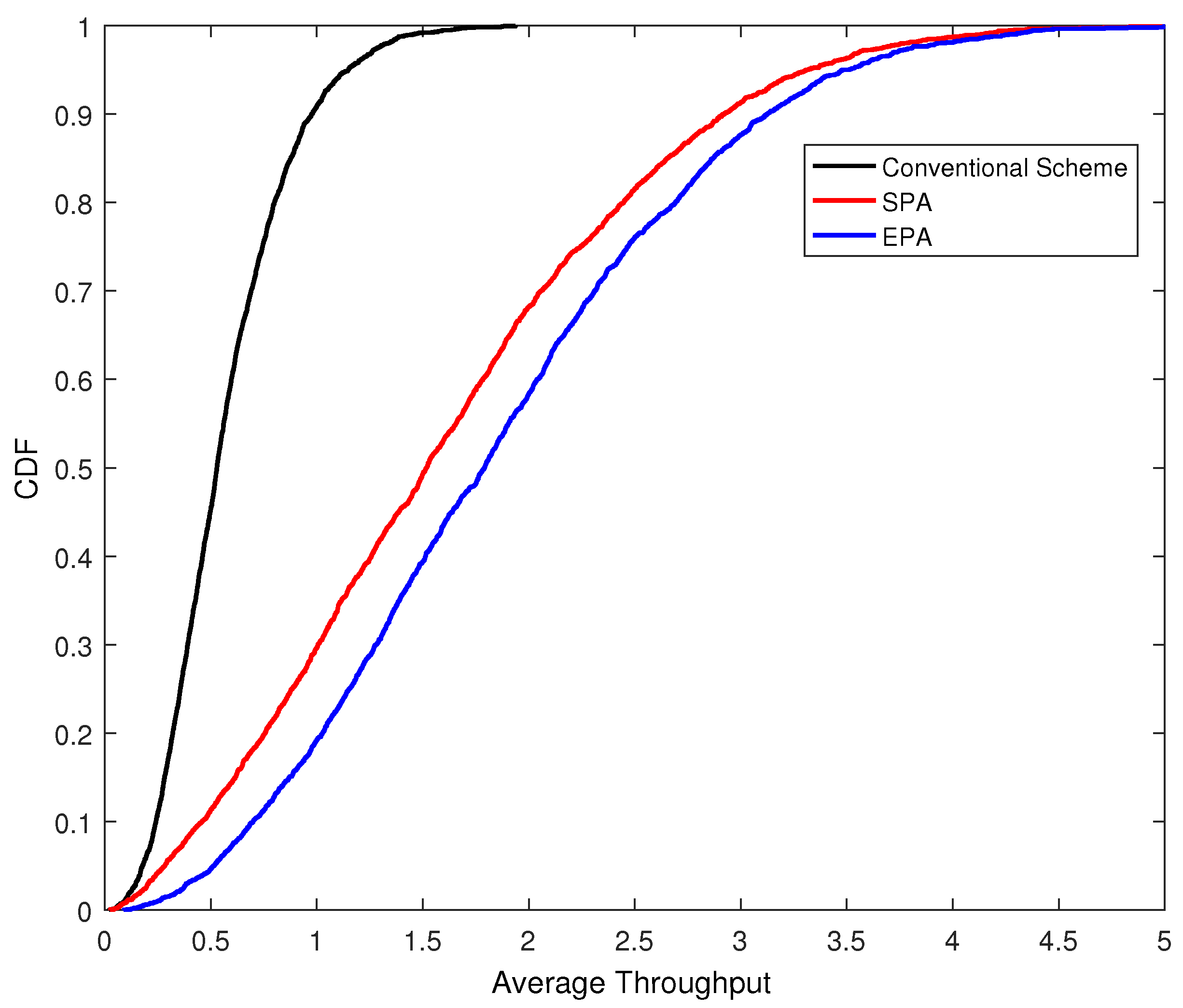
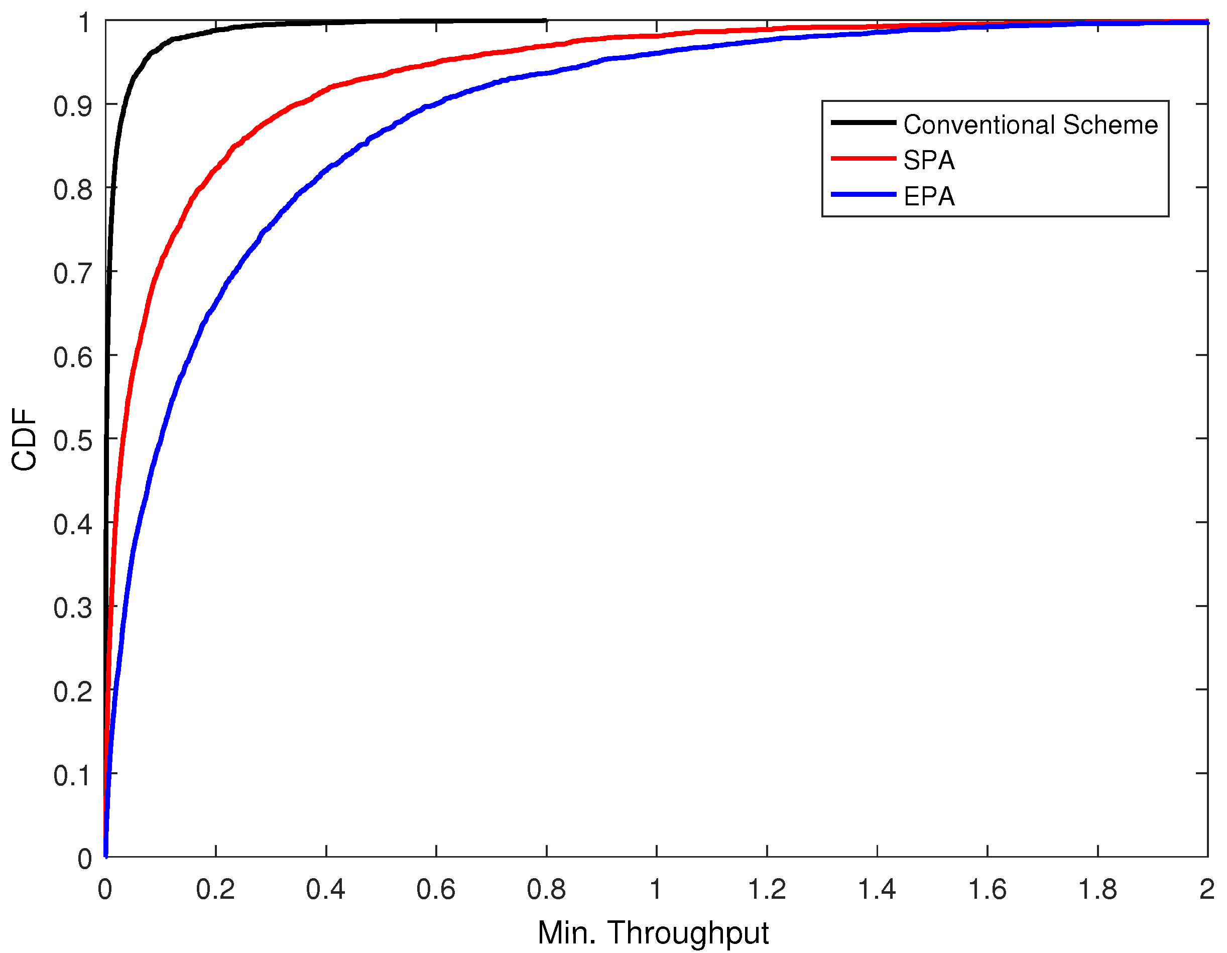
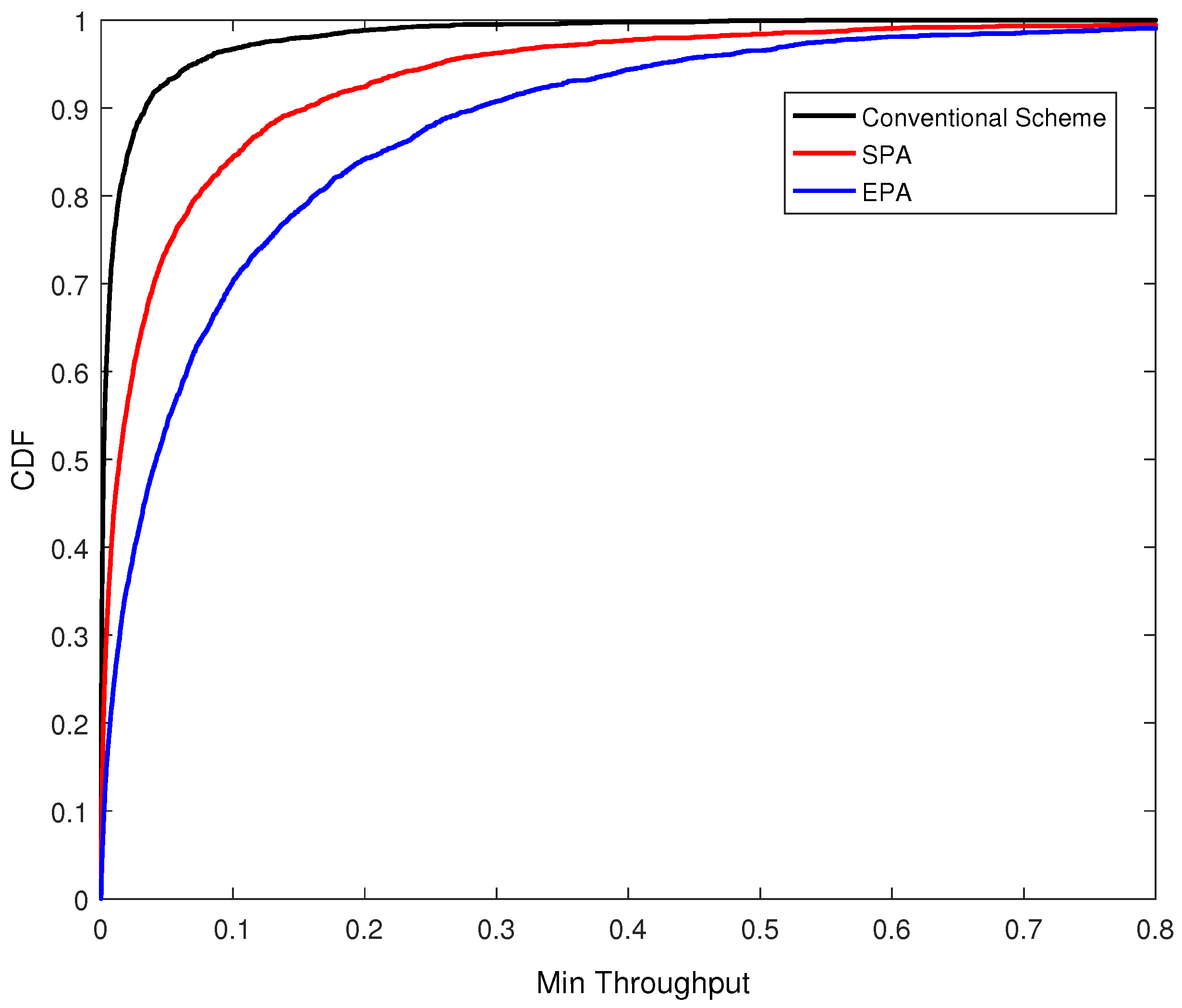
- We formulate the pilot assignment as an optimization problem and develop a heuristic algorithm, in order to maximize the minimum throughput considering the reduction in the inter-cell interference pilot contamination.
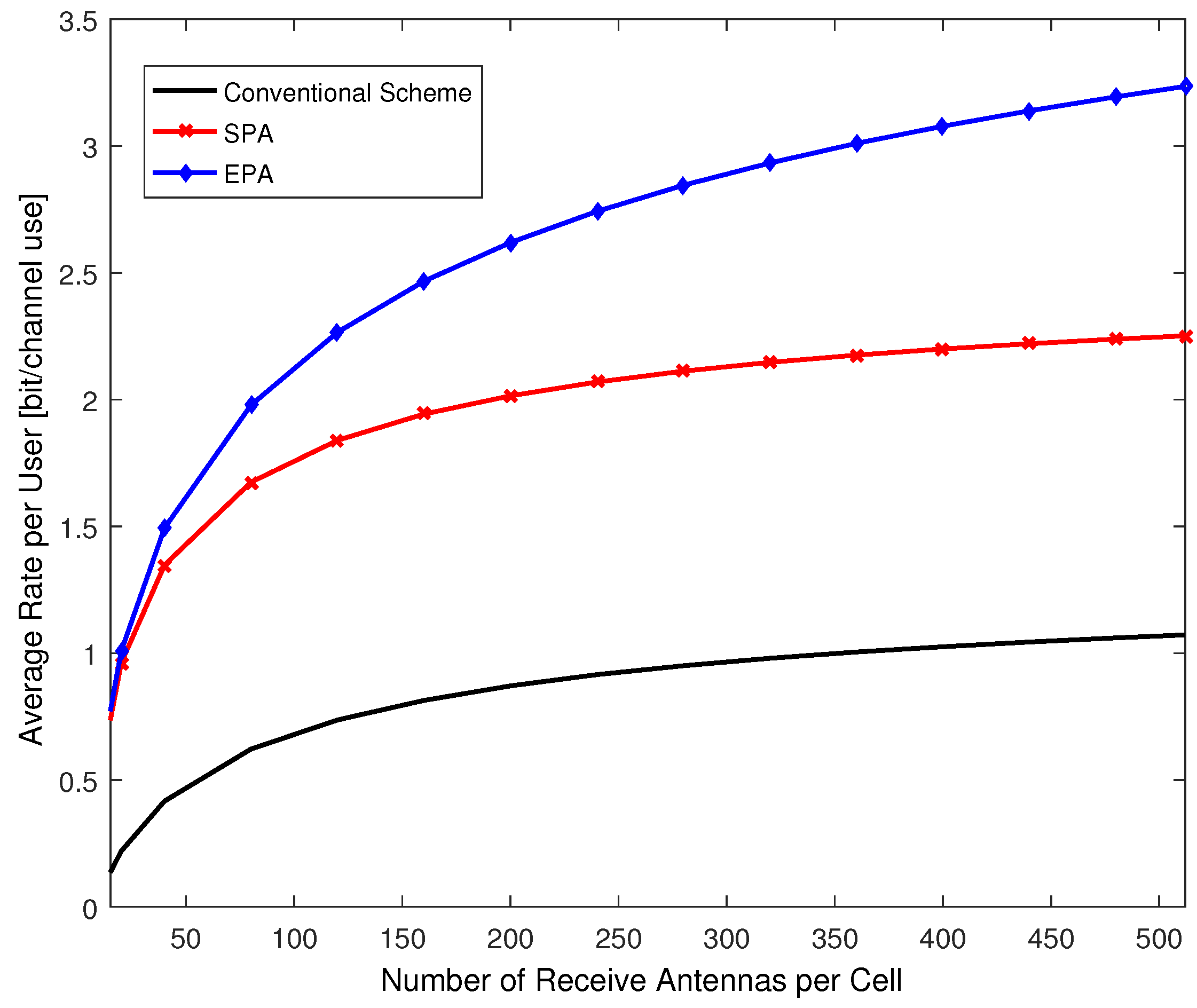
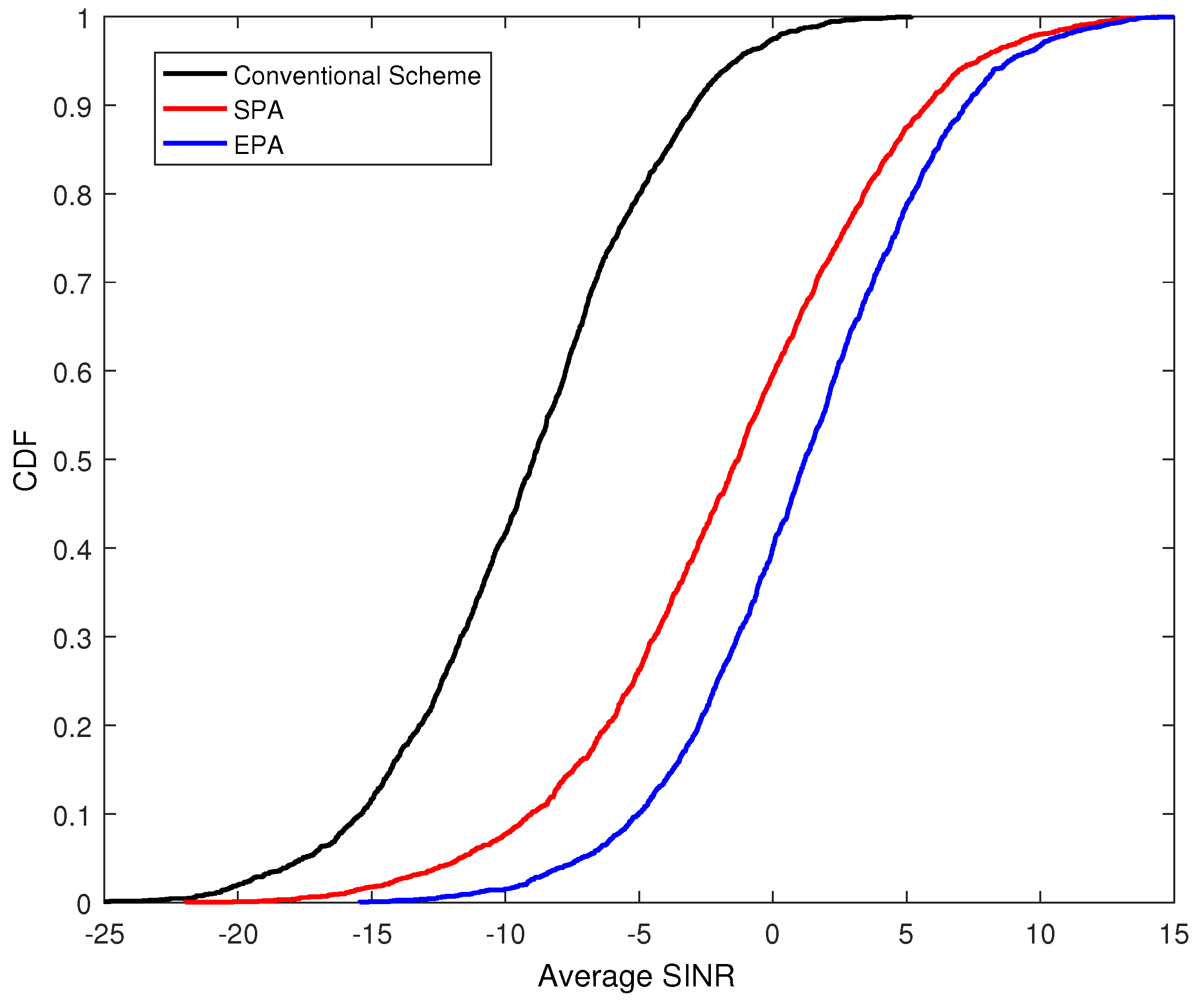
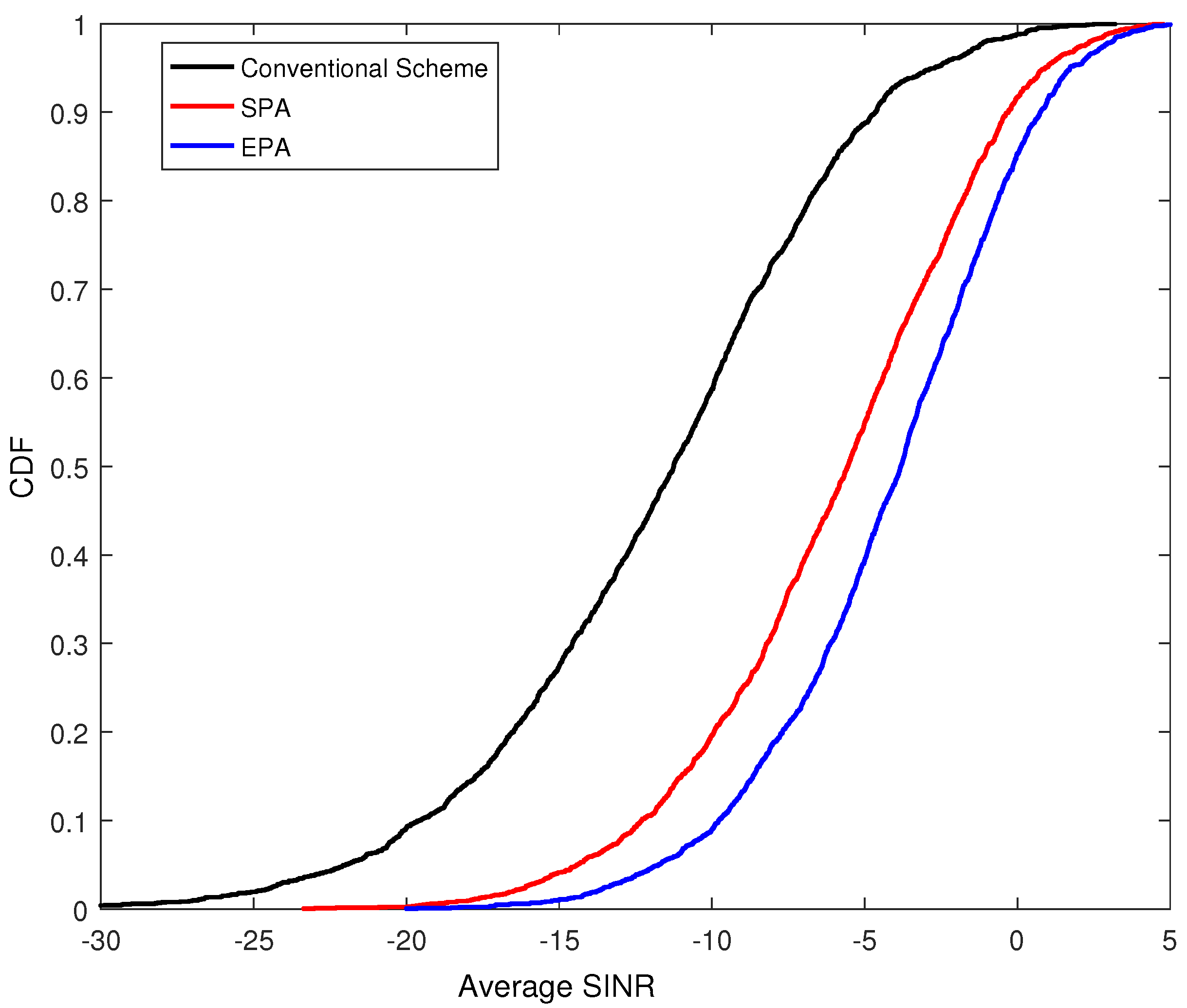
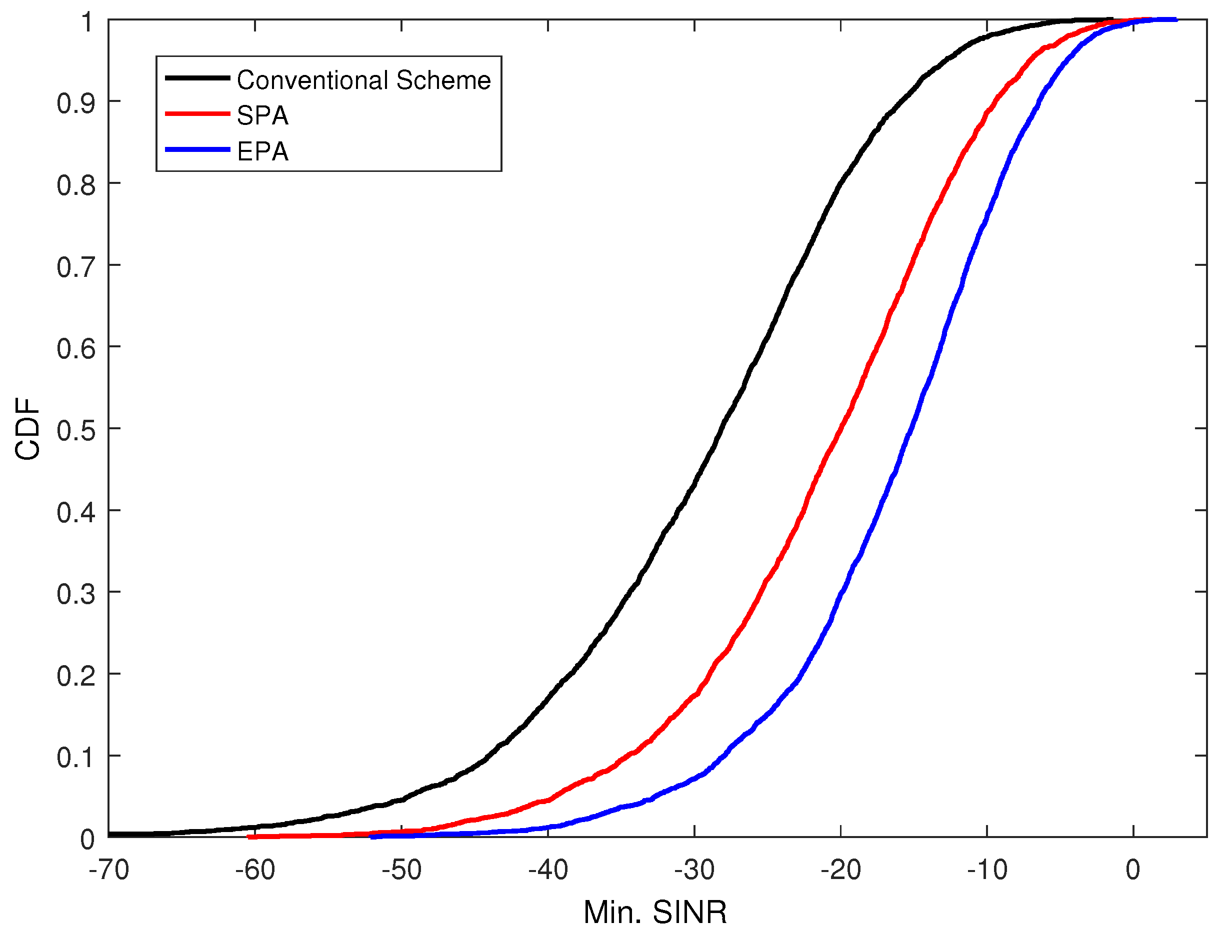
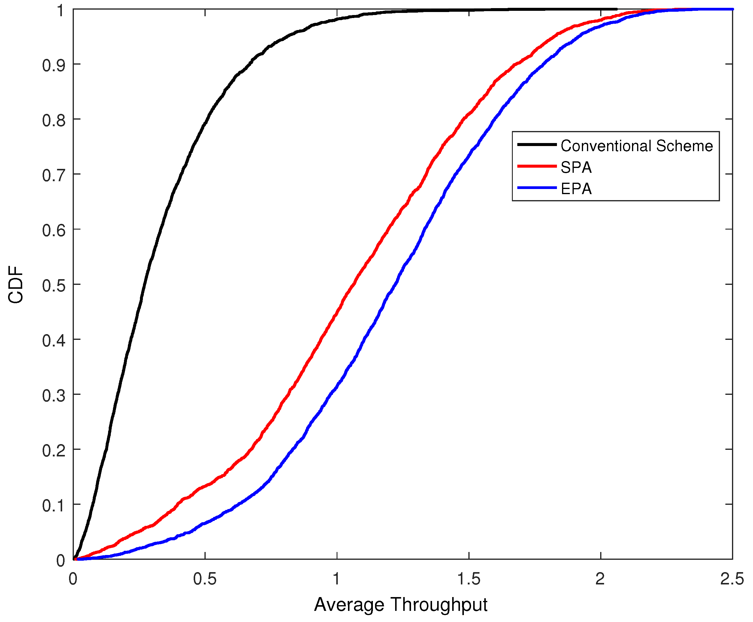
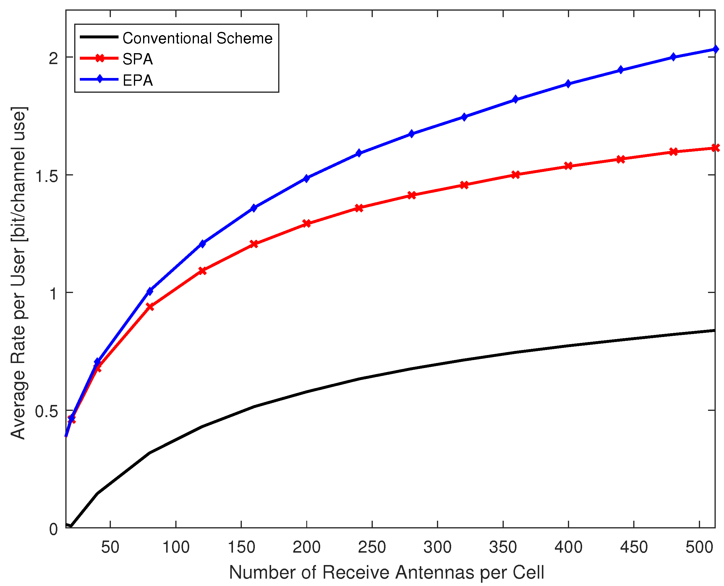
- We evaluate the performance of the proposed mechanism in terms of signal-to-interference-plus-noise ratio (SINR), and uplink rate with an extensive MATLAB simulation.
- We compare our work with SPA and other conventional schemes.
2. Related Work
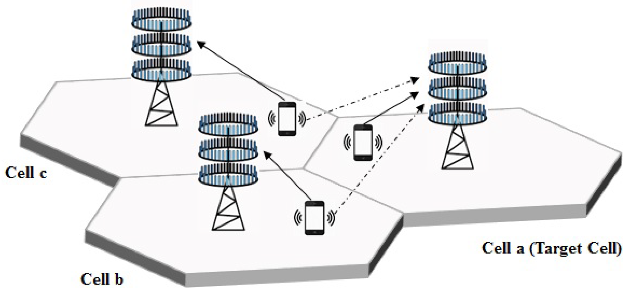
3. System Model
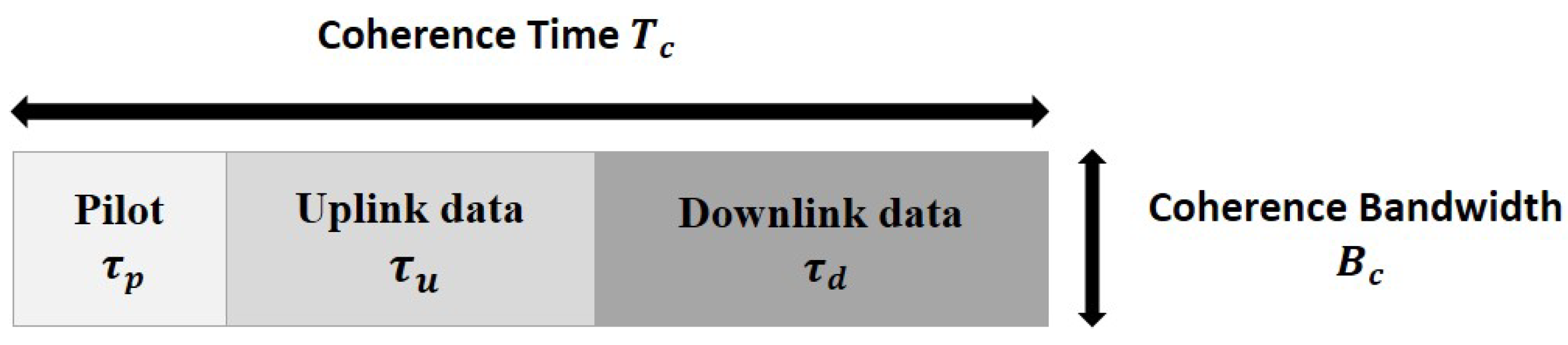
4. Pilot Contamination and Achievable Uplink Rate
5. Proposed Scheme
5.1. Problem Formulation
5.2. Proposed Solution
| Algorithm 1 Efficient Pilot Assignment (EPA). |
|
6. Simulation Results
7. Conclusions
Author Contributions
Funding
Conflicts of Interest
References
- Boccardi, F.; Heath, R.W.; Lozano, A.; Marzetta, T.L.; Popovski, P. Five disruptive technology directions for 5G. IEEE Commun. Mag. 2014, 52, 74–80. [Google Scholar] [CrossRef] [Green Version]
- Marzetta, T.L. Noncooperative cellular wireless with unlimited numbers of base station antennas. IEEE Trans. Wirel. Commun. 2010, 9, 3590–3600. [Google Scholar] [CrossRef]
- Lim, Y.G.; Chae, C.B.; Caire, G. Performance analysis of massive MIMO for cell-boundary users. IEEE Trans. Wirel. Commun. 2015, 14, 6827–6842. [Google Scholar] [CrossRef]
- Larsson, E.G.; Edfors, O.; Tufvesson, F.; Marzetta, T.L. Massive MIMO for next generation wireless systems. IEEE Commun. Mag. 2014, 52, 186–195. [Google Scholar] [CrossRef] [Green Version]
- Rusek, F.; Persson, D.; Lau, B.K.; Larsson, E.G.; Marzetta, T.L.; Edfors, O.; Tufvesson, F. Scaling up MIMO: Opportunities and challenges with very large arrays. IIEEE Signal Process. Mag. 2013, 30, 40–60. [Google Scholar] [CrossRef]
- Björnson, E.; Larsson, E.G.; Debbah, M. Optimizing multi-cell massive MIMO for spectral efficiency: How many users should be scheduled? In Proceedings of the 2014 IEEE Global Conference on Signal and Information Processing (GlobalSIP), Atlanta, GA, USA, 3–5 December 2014. [Google Scholar] [CrossRef]
- Rajatheva, N.; Osseiran, A.; Monserrat, J.F.; Marsch, P. 5G Mobile and Wireless Communications Technology; Osseiran, A., Monserrat, J.F., Marsch, P., Eds.; Cambridge University Press: Cambridge, UK, 2016; ISBN 978-1-107-13009-8. [Google Scholar]
- Björnson, E.; Larsson, E.G.; Marzetta, T.L. Massive MIMO: Ten myths and one critical question. IEEE Commun. Mag. 2016, 54, 114–123. [Google Scholar] [CrossRef]
- Jose, J.; Ashikhmin, A.; Marzetta, T.; Vishwanath, S. Pilot Contamination and Precoding in Multi-Cell TDD Systems. IEEE Trans. Wirel. Commun. 2011, 10, 2640–2651. [Google Scholar] [CrossRef] [Green Version]
- Björnson, E.; Hoydis, J.; Sanguinetti, L. Massive MIMO Networks: Spectral, Energy, and Hardware Efficiency. IFound. Trends Signal Process. 2017, 11, 154–655. [Google Scholar] [CrossRef]
- Zhu, X.; Wang, Z.; Dai, L.; Qian, C. Smart Pilot Assignment for Massive MIMO. IIEEE Commun. Lett. 2015, 19, 1644–1647. [Google Scholar] [CrossRef]
- Dao, H.T.; Kim, S. Vertex Graph-Coloring-Based Pilot Assignment With Location-Based Channel Estimation for Massive MIMO Systems. IEEE Access 2018, 6, 4599–4607. [Google Scholar] [CrossRef]
- Kim, K.; Lee, J.; Choi, J. Deep Learning Based Pilot Allocation Scheme (DL-PAS) for 5G Massive MIMO System. IIEEE Commun. Lett. 2018, 22, 828–831. [Google Scholar] [CrossRef]
- Akbar, N.; Yan, S.; Yang, N.; Yuan, J. Location-Aware Pilot Allocation in Multicell Multiuser Massive MIMO Networks. IEEE Trans. Veh. Technol. 2018, 67, 7774–7778. [Google Scholar] [CrossRef] [Green Version]
- Muppirisetty, L.S.; Charalambous, T.; Karout, J.; Fodor, G.; Wymeersch, H. Location-Aided Pilot Contamination Avoidance for Massive MIMO Systems. IEEE Trans. Wirel. Commun. 2018, 17, 2662–2674. [Google Scholar] [CrossRef] [Green Version]
- Sohn, J.; Yoon, S.W.; Moon, J. On Reusing Pilots Among Interfering Cells in Massive MIMO. IEEE Trans. Wirel. Commun. 2017, 16, 8092–8104. [Google Scholar] [CrossRef] [Green Version]
- Zhu, X.; Wang, Z.; Qian, C.; Dai, L.; Chen, J.; Chen, S.; Hanzo, L. Soft Pilot Reuse and Multi-Cell Block Diagonalization Precoding for Massive MIMO Systems. IEEE Trans. Veh. Technol. 2016, 65, 3285–3298. [Google Scholar] [CrossRef]
- ZLiu, J.; Li, Y.; Zhang, H.; Guo, S. Efficient and Fair Pilot Allocation for Multi-cell Massive MIMO Systems. In Proceedings of the 2017 9th International Conference on Wireless Communications and Signal Processing (WCSP), Nanjing, China, 11–13 October 2017. [Google Scholar] [CrossRef]
- Ma, S.; Xu, E.L.; Salimi, A.; Cui, S. A Novel Pilot Assignment Scheme in Massive MIMO Networks. IEEE Commun. Lett. 2018, 7, 262–265. [Google Scholar] [CrossRef]
- Wang, H.; Huang, Y.; Jin, S.; Du, Y.; Yang, L. Pilot Contamination Reduction in Multi-cell TDD Systems with Very Large MIMO Arrays. Wirel. Pers. Commun. 2017, 96, 5785–5808. [Google Scholar] [CrossRef]
- Du, T.; Wang, Y.; Wang, J.; Du, Y.; Yang, L. Multi-cell Joint Optimization to Mitigate Pilot Contamination for Multi-Cell Massive MIMO Systems. In Proceedings of the 2017 IEEE 85th Vehicular Technology Conference (VTC Spring), Sydney, NSW, Australia, 4–7 June 2017. [Google Scholar] [CrossRef]
- Wang, P.; Zhao, C.; Zhang, Y.; Stuber, G.L. A Novel Pilot Assignment Approach for Pilot Decontaminating in Massive MIMO Systems. In Proceedings of the 2017 IEEE Wireless Communications and Networking Conference (WCNC), San Francisco, CA, USA, 19–22 March 2017. [Google Scholar] [CrossRef]
- Zhao, M.; Zhang, H.; Guo, S.; Yuan, D. Joint Pilot Assignment and Pilot Contamination Precoding Design for Massive MIMO Systems. In Proceedings of the 2017 26th Wireless and Optical Communication Conference (WOCC), Newark, NJ, USA, 7–8 April 2017. [Google Scholar] [CrossRef]
- Fernandes, F.; Ashikhmin, A.; Marzetta, T.L. Inter-Cell Interference in Noncooperative TDD Large Scale Antenna Systems. IEEE J. Sel. Areas Commun. 2013, 31, 192–201. [Google Scholar] [CrossRef] [Green Version]
- Chen, Z.; Yang, C. Pilot decontamination in wideband massive MIMO systems by exploiting channel sparsity. IEEE Trans. Wirel. Commun. 2016, 15, 5087–5100. [Google Scholar] [CrossRef]
- Björnson, E.; Matthaiou, M.; Debbah, M. Massive MIMO with Non-Ideal Arbitrary Arrays: Hardware Scaling Laws and Circuit-Aware Design. IEEE Trans. Wirel. Commun. 2015, 14, 4353–4368. [Google Scholar] [CrossRef]
- Li, M.; Jin, S.; Gao, X. Spatial Orthogonality-Based Pilot Reuse for Multi-cell Massive MIMO Transmission. In Proceedings of the 2013 International Conference on Wireless Communications and Signal Processing, Hangzhou, China, 24–26 October 2013. [Google Scholar] [CrossRef]
- Ashikhmin, A.; Marzetta, T. Pilot Contamination Precoding in Multi-Cell Large Scale Antenna Systems. In Proceedings of the 2012 IEEE International Symposium on Information Theory Proceedings, Cambridge, MA, USA, 1–6 July 2012. [Google Scholar] [CrossRef]
- Muller, R.; Cottatellucci, L.; Vehkapera, M. Blind pilot decontamination. IEEE J. Sel. Top. Signal Process. 2014, 8, 773–786. [Google Scholar] [CrossRef]
- NGO, H.Q.; Larsson, E.G.; Marzetta, T.L. Energy and Spectral Efficiency of Very Large Multiuser. IEEE Trans. Wirel. Commun. 2013, 61, 1436–1449. [Google Scholar] [CrossRef]
- Sesia, S.; Toufik, I.; Baker, M. Network Architecture and Protocols. In LTE-The UMTS Long Term Evolution: From Theory to Practice; John Wiley & Sons Ltd.: Chichester, UK, 2011; ISBN 978-0-470-66025-6. [Google Scholar]
- Zhu, X.; Dai, L.; Wang, Z. Graph coloring based pilot allocation to mitigate pilot contamination for multi-cell massive mimo systems. IEEE Commun. Lett. 2015, 19, 1842–1845. [Google Scholar] [CrossRef]
- Sarkar, T.K.; Ji, Z.; Kim, K.; Medouri, K.; Salazar-Palma, M. A survey of various propagation models for mobile communication. IEEE Antennas Propag. Mag. 2003, 45, 51–82. [Google Scholar] [CrossRef]


| Parameter | Value (for Figure 3, Figure 4, Figure 5, Figure 6, Figure 7, Figure 8, Figure 9, Figure 10, Figure 11 and Figure 12) | Value (for Figure 13) |
|---|---|---|
| Number of Cells L | 7 | 7 |
| Number of BS Antennas M | ||
| Number of users in each cell K | 8 | 20 |
| Cell RadiusR | 500 m | 300 m |
| Cell edge SNR | 15 dB | 20 dB |
| Path-loss Exponent | 3 | 3 |
| Shadow Fading Standard Deviation | 8 | 8 |
| Thermal Noise Variance | −174 dBm/H | −174 dBm/H |
© 2019 by the authors. Licensee MDPI, Basel, Switzerland. This article is an open access article distributed under the terms and conditions of the Creative Commons Attribution (CC BY) license (http://creativecommons.org/licenses/by/4.0/).
Share and Cite
Al-hubaishi, A.S.; Noordin, N.K.; Sali, A.; Subramaniam, S.; Mohammed Mansoor, A. An Efficient Pilot Assignment Scheme for Addressing Pilot Contamination in Multicell Massive MIMO Systems. Electronics 2019, 8, 372. https://doi.org/10.3390/electronics8040372
Al-hubaishi AS, Noordin NK, Sali A, Subramaniam S, Mohammed Mansoor A. An Efficient Pilot Assignment Scheme for Addressing Pilot Contamination in Multicell Massive MIMO Systems. Electronics. 2019; 8(4):372. https://doi.org/10.3390/electronics8040372
Chicago/Turabian StyleAl-hubaishi, Ahmed S., Nor Kamariah Noordin, Aduwati Sali, Shamala Subramaniam, and Ali Mohammed Mansoor. 2019. "An Efficient Pilot Assignment Scheme for Addressing Pilot Contamination in Multicell Massive MIMO Systems" Electronics 8, no. 4: 372. https://doi.org/10.3390/electronics8040372