Access Adaptive and Thread-Aware Cache Partitioning in Multicore Systems


1
Institute of VLSI Design, Zhejiang University, Hangzhou 310027, China
2
School of Information & Electronic Engineering, Zhejiang Gongshang University, Hangzhou 310018, China
*
Author to whom correspondence should be addressed.
Electronics 2018, 7(9), 172; https://doi.org/10.3390/electronics7090172
Submission received: 20 July 2018
/
Revised: 12 August 2018
/
Accepted: 27 August 2018
/
Published: 1 September 2018
(This article belongs to the Special Issue Distributed Computing and Storage)
Abstract
:Cache partitioning is a successful technique for saving energy for a shared cache and all the existing studies focus on multi-program workloads running in multicore systems. In this paper, we are motivated by the fact that a multi-thread application generally executes faster than its single-thread counterpart and its cache accessing behavior is quite different. Based on this observation, we study applications running in multi-thread mode and classify data of the multi-thread applications into shared and private categories, which helps reduce the interferences among shared and private data and contributes to constructing a more efficient cache partitioning scheme. We also propose a hardware structure to support these operations. Then, an access adaptive and thread-aware cache partitioning (ATCP) scheme is proposed, which assigns separate cache portions to shared and private data to avoid the evictions caused by the conflicts from the data of different categories in the shared cache. The proposed ATCP achieves a lower energy consumption, meanwhile improving the performance of applications compared with the least recently used (LRU) managed, core-based evenly partitioning (EVEN) and utility-based cache partitioning (UCP) schemes. The experimental results show that ATCP can achieve 29.6% and 19.9% average energy savings compared with LRU and UCP schemes in a quad-core system. Moreover, the average speedup of multi-thread ATCP with respect to single-thread LRU is at 1.89.
1. Introduction
For the desired performance, chip multiprocessor (CMP) architecture has been widely used for decades. Major vendors like Intel [1] and AMD [2] have developed series of CMPs in general-purpose computers. Currently, the main competition field of CMPs has turned to embedded systems, in which energy optimization is essential, since many of them are powered by batteries.
Multicore architectures are typically equipped with a small private L1 cache for each core and a large shared L2 cache. These cache memories not only make up a large portion of the total area but also consume a large fraction of the total energy of a chip. In some designs, the energy consumption of the cache memories reaches as high as over 50% of the whole chip [3,4,5]. Luckily, the energy consumption of the relatively large L2 cache can be cut down by turning off the unused ways [6,7,8,9] or using a drowsy cache [5,10] for implementation. Many studies [3,11,12] also show that multiple tasks running in a shared cache interfere with each other, because they access the shared cache simultaneously and this is called, for example, cache thrashing. Cache partitioning is an effective way of tackling this problem. Cache coloring [13,14] is a promising software-based cache partitioning scheme, which prevents the tasks from accessing the same set in the shared cache by controlling the virtual-to-physical address translation. Besides, there are other promising cache management techniques that consider eviction policy, insertion policy and promotion policy. Eviction policy determines which cache line should be evicted when refilling the cache. Insertion policy determines the location in which to place the incoming cache line when refilling the cache. Promotion policy determines how to update the hit cache line in the replacement priority order. The thread-aware Dynamic Insertion Policy (TADIP) [15,16,17] dynamically chooses the insertion policies of the traditional LRU policy and the Bimodal Insertion Policy, according to the cache requirements of different applications.
Many of the state-of-the-art cache partitioning techniques study single-thread applications [3,4,5,11,12,18]. To the best of our knowledge, no previous studies have talked about cache partitioning for multi-thread applications and studied the actual cache requirements of the threads of a task on multicore platforms. Currently, multi-threading in multicore systems is the trend, and most tasks benefit a lot from running in multi-thread mode [19]. For the applications that can be partitioned into threads in multicore platforms, it is beneficial to run in multi-thread mode. While for the applications that are not partitionable into threads that happens in certain big data servers, the only way is to utilize ultra-fine grain instruction level parallelism or ultra-coarse grain process level parallelism. Moreover, new multi-thread benchmarks [20,21] have been developed to test the multicore architectures.
Previous studies are not suitable for multi-thread tasks, the detailed reasons are shown in Section 3. We believe that considering multi-thread during the partitioning of a shared cache can achieve lower energy consumption and higher performance than that when only single-thread is considered. This is due to the additional exploration space for partitioning in multi-thread mode and single-thread mode can be regarded as a special case of the multi-thread mode. When extended to scheduling problem, scheduling in multi-thread mode has a larger exploration space than that in single-thread mode and by fully exploiting the larger exploration space a global optimal energy or performance can be achieved. We also believe that classifying the shared L2 cache accessing type into different categories helps to alleviate the conflictions in the shared L2 cache. Accessing shareability type in a shared cache can be private or shared for threads, and the corresponding cache allocation can also differ.
In this paper, we handle the cache partitioning problem for multi-thread tasks that simultaneously run on a multicore platform and the aim is to optimize the energy consumption of the shared L2 cache. To the best of our knowledge, this work is the first to study cache partitioning taking multi-thread and accessing type into account on multicore platforms. We study the multi-thread tasks and compare their behavior with that of their single-thread counterparts. Furthermore, we classify L2 cache data into shared type and private type, then analyze the effect on data conflictions and performance. Based on the analysis above, we propose a hardware architecture to support the data-type-aware cache partitioning. Accordingly, we develop a two-stage mixed integer linear programming (TS-MILP) scheme to partition a shared cache for the given multi-thread tasks. In the first stage, we separately study each task under various given numbers of cache ways. The objective is to figure out the number of threads and threads’ corresponding cache allocations that the energy consumption of the shared cache is minimized. In the second stage, we study the tasks in a task set globally and figure out the numbers of cache ways for each task in a task set. The objective is to minimize the total energy of the shared cache consumed by all the tasks.
In this paper, we make the following contributions:
- We consider multi-thread applications’ execution on multicore platforms and propose a thread-aware cache partitioning scheme.
- We introduce the concept of the Share/Private (S/P) shareability type for multicore multi-thread applications and find a way of categorizing the shareability types and obtaining S/P data for each thread.
- We present and implement a hardware mechanism to support suitable S/P cache partitioning for multi-thread tasks. Thread aware cache monitor (TACM) is proposed and cache way access permission registers (WAPR) are implemented to partition a shared cache.
- We propose MILP formulations to partition a shared cache for all the tasks in thread level to optimize the total energy consumption of the shared cache.
- We study the impact of multi-threading and the shareability type categorization and we also evaluate our proposed cache partitioning scheme through real-life applications running in our implemented FPGA logic.
The rest of this paper is organized as follows. Section 2 reviews the related work. Section 3 describes multi-threading and shareability type classifying examples to illustrate our motivations. Section 4 depicts WAPR, TACM and their cooperation logic when partitioning a shared cache. Section 5 presents the MILP formulation for cache partitioning. Experimental results and evaluation analysis are shown in Section 6. Section 7 concludes the paper.
2. Related Work
2.1. Cache Partitioning
In recent years, shared cache partitioning in multicore systems has been extensively studied by many institutions, bringing a lot of literatures. In a typical multicore architecture, as shown in Figure 1, cores have their private L1 caches and a shared L2 cache. All these caches are on-chip and inside the multicore architecture.
The state-of-the-art studies propose cache partitioning techniques for various purposes. Many [11,17,18,22] of them focused on reducing the total number of cache misses or improving the performance. A representative work was proposed by Qureshi et al. [11]. It was an online cache partitioning technique to minimize the whole number of cache misses based on utility monitors (UMON). Other design objectives are also presented many times. Yu and Petrov [23] aimed to increase the throughput of the memory by partitioning the L2 cache according to each task’s bandwidth requirements. Cook et al. [19] exploited the cache behavior by many experiments on real hardware measurements and analyzed each aspect; they guaranteed the responsiveness by co-scheduling background applications with foreground applications and partitioned the shared cache for them. Authors in Reference [24,25] presented cache partitioning techniques that improved the throughput of most workloads by partitioning caches at cache line granularity and considering write-back operations separately. There are also many studies that talk about fairness and throughput [12,22,26]. Kim et al. [12] kept good fairness for applications by studying the relationship between fairness and throughput in details and proposed algorithms to partition a shared cache both dynamically and statically. There are more studies [3,4,5,18,19,25] that take energy efficiency into account and the partitioning schemes cover methods from hardware to software and hybrid of them.
All these studies only considered single-thread tasks during cache partitioning. Only Cook et al. in Reference [19] related about multi-thread applications, however they did not partition a shared cache at thread level and just performed some experiments on thread scalability instead. No multi-thread applications were studied, not to mention shareability type categorization among threads.
2.2. Cache Monitor and LRU Policy Inclusion Property
In order to design a cache partitioning scheme on a specific target, we should capture some basic data which include cache miss numbers [5,11,23,27], cache access numbers [3,11,22,27], cycle numbers [11,27] and so on. It is very time-consuming to obtain these data by software, so utilizing hardware cache monitors is a preferable way in general.
Cache miss rate is an elementary value for a cache and it is the foundation of many previous studies. For a well-designed cache partitioning scheme, the partitioner should know the cache miss rates of the task when the task is assigned to different portions of the shared cache. Take way-based cache partitioning [4,11,18,23,27] as an example, cache miss rates of an application under 1-way, 2-way … N-way (N is the total number of ways) should be known before cache partitioning. A straightforward method to obtain these data is to implement N tag directories that are organized from 1 to N way set-associative. Besides, N access/hit counters and N miss counters should be implemented as monitors. However, the hardware cost is too expensive. Another direct method is to run each application N times to get the cache miss rates information from 1-way to N-way but this is very time-consuming especially when the experiments are done through simulations in which the execution time is usually intolerable.
Fortunately, for the commonly used Least Recently Used (LRU) replacement policy for caches, its inclusion property can be used to handle the problems of expensive hardware cost and time consumption. Inclusion property or stack property is first studied by Mattson [28] and it is quoted and developed by many other researchers [11,27,29,30]. Specifically, inclusion property is that: in an LRU managed cache, an access hit in N sized cache will certainly be an access hit in the cache which is larger than N sized. For an N-way set-associative cache, the cache miss rates under different cache way size can be monitored by N + 1 set-specific counters, which are denoted by to . Figure 2 shows an example of N = 8. to count the access hits from most recently used block (MRU) to least recently used block (LRU) respectively. counts the access misses. When an access matches the address located in the position of the LRU stack, increases by one and the other counters keep their values. If the access is a miss one, increases and the other counters keep their values. By instrumenting an N-way set-associative cache with the counters to and submitting a sequence of accesses, not only are we able to know the miss rate of such cache but also the miss rate that any other k-way cache would have had under the same access sequence. The miss rate for a k-way cache denoted as Rm(k) is shown as follows:
where k = 1, 2, …, N.
Figure 2 illustrates how these counters are implemented and how the inclusion property works in the LRU replacement policy. For the whole 8-way LRU cache, the miss rate can be obtained with (1), that is, . Another example, for a 5-way LRU cache, the hit counters to and the miss counter are all regarded as cache miss counters. Then the miss rate is . As long as the cache miss rates of different cache sizes are got, cache partitioning algorithm can be developed base on the obtained data. Previous literatures utilized the LRU stack counters for single-thread tasks but they cannot work when it comes to multi-thread applications, as we discuss in Section 3.1.
2.3. Cache Energy Model
There are many ways to evaluate the energy consumption of the cache, such as using hardware insider monitor [19] or using cache energy model. For early stage research and development, using hardware monitor is not realistic. We use a representative cache energy model [4,7,8,31] to calculate the energy dissipation of the cache subsystem denoted as , which consists of dynamic energy and static energy . We have the following equations:
where
and are the total access number and miss number of the shared L2 cache. and denote the energy consumed by a single cache hit and miss, respectively. is the energy consumed when accessing the off-chip memory. is the energy dissipation when the core is waiting for the data from the off-chip memory. is the energy for filling the fetched data into a cache line. is the static power of the shared cache and is the total execution time of a task. The value for , and of a certain cache can be obtained with the cache modeling tools like CACTI [32]. The same method in Reference [7] can be used to obtain the value of and , which refers to the specifications.
3. Motivation
3.1. Multi-Threading
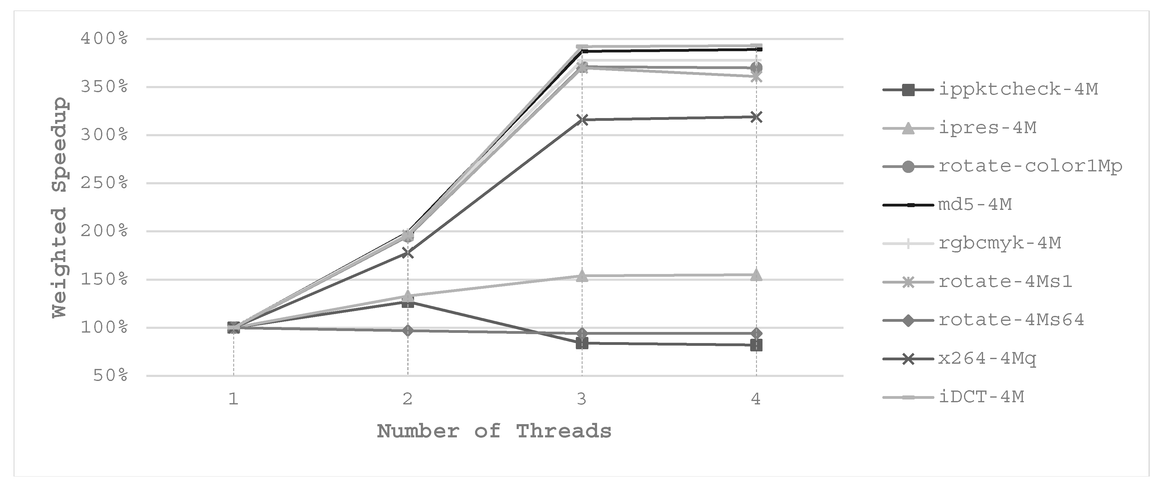
Multi-threading offers a chance to optimize the energy consumption as well as the performance but none of the related studies mentioned above discussed cache partitioning for multi-thread tasks. Figure 3 depicts the weighted speedup of the parallel benchmarks in MultiBench [20], with various numbers of threads on a quad-core platform. We notice that there is a region for many applications that the execution time scales well with the corresponding number of threads. For example, md5-4M executes as fast as nearly 2× and 4× with 2-thread and 4-thread compared with 1-thread, respectively. A similar experimental result is shown in Reference [19]. It is worth mentioning that this comparison is done with the same cache size, that is, the number of cache ways is fixed.
But when multiple threads are running in parallel, there will be more cache size to be allocated. For instance, in a dual-core system with an even-partitioned 8-way L2 cache, when task A is running in single-thread mode with another task B, task A can only use half of the whole L2 cache. Whereas when it comes to 2-thread mode, task A can use all the L2 cache because each core is running one of the 2 threads of task A and no other task shares the cache. During this time, task B is not executing but it will be executed when task A finishes. In this way, multi-thread tasks can achieve a better performance due to the additional cache space. On the other hand, the number of self-evictions of the multi-thread task is increased and this would cause performance degradation. As multi-thread tasks may execute faster, the idle time is prolonged to shut down the whole or part of L2 cache for energy savings.
As for the scheduling problem, there is a great opportunity for multi-thread tasks to save energy consumption. Multi-threading shortens the execution time of an application as it reduces the inter-thread interferences and provides the task with additional cache space, so that it offers much larger scheduling exploration space for the scheduler. Figure 4 illustrates how the scheduler can achieve better task dispatching scheme with multi-threading. There are 3 tasks named T1, T2 and T3 to be scheduled in a dual-core system. The shared 8-way L2 cache is partitioned in way granularity and the deadline of the tasks is 10 ms. The execution time of T1, T2 and T3 in single-thread mode is 5 ms, 4 ms and 10 ms, respectively. In single-thread mode, T1 and T3 start simultaneously and T2 starts after T1 finishes. T1 and T2 occupy the same three ways (3W) under a cache partitioning scheme and the other five ways (5W) are allocated to T3. In multi-thread mode, the scheduling is different. First, the tasks are running with 2 threads. T1θ0 and T1θ1 represent thread0 and thread1 of T1 and so it is with T2 and T3. Second, cache ways can be classified into two categories, private ways (PW) and shared ways (SW). In this case, the threads of T1 share 3 cache ways and so are the threads of T2. T3θ0 shares 3 cache ways with T3θ1 and each of them has one private cache way.
We assume that the total L2 access and miss numbers are the same in multi-thread and single-thread mode. Therefore, the dynamic energy dissipation in the two modes are the same, denoted as . In reality, tasks running in multi-thread mode miss less in L2 cache. As shown in Section 6, applications running in multi-thread mode with shareability type categorization always have fewer total L2 cache misses, since inter-thread interferences are avoided. This follows the same rule that cache partitioning among different tasks will eliminate the inter-task interference and decrease the cache miss rate [5]. Moreover, the total number of L2 cache reference of an application in single-thread and multi-thread mode are usually the same, as it is determined by the characteristic of the application. So, with the same number of cache references and fewer cache misses, the dynamic energy in multi-thread mode cannot be more than that in single-thread mode. Next, we compare the static energy dissipation of the motivational example in Figure 4. Let static power of a single cache way be . Then the total static energy consumption of the shared cache in single-thread and multi-thread mode are and . Let denote the power consumption of the core. Then total energy consumption in single-thread and multi-thread mode are and , respectively. For modern L2 caches, and are of the same magnitude. So, it is very likely that is less than and is less than . The calculation process is shown in Appendix A.
3.2. Shareability Type Categorization
In a multicore architecture, L2 cache is typically shared by all the cores and the user data and instructions are all disorganized inside it. However, the data and instructions exhibit distinct characteristics which lead to different behavior in L2 cache [33]. In terms of shareability type, instructions can be purely private or all shared because no coherent realizations can be done for it. But user data consists of both private data and shared data. We assume:
- Shared data is read or written by more than one thread.
- Private data is used by only one thread.
Moreover, there are situations that private data should be protected [34]. So, the shareability type categorization in a shared cache is needed. To cope with these problems, the shared cache should be aware of the shareability of the data inside it.
As far as we know, this is the first study that takes shareability type into consideration when partitioning shared caches in multi-thread mode. Besides the interference elimination talked above, a shareability type categorized cache can obtain better energy efficiency. Figure 5 compares the data placement of our proposed thread-aware cache with that of the un-managed cache and frequently cited Utility-based Cache Partitioning (UCP) managed cache [11]. There shows a L2 cache and the data in each set and way of a dual-core processor. The data consists of private data and shared data and the owner of the shared data is the core that most recently accesses the shared data. For clarity, core0’s data is white and core1’s data is shadowed in gray and the unused blocks are marked in yellow. In an un-managed cache, any type of data can be in any cache way. In a UCP cache, each core’s owned size in each set is fixed. For instance, core0 owns 5 ways of any sets and core1 occupies the other 3 ways. But the shared data are double counted in this scheme, because the UCP’s UMON counts the data of each core in their work.
Assume that the shared data A, B, C, private data D, E, F, G are in the same set of the L2 cache. The data access sequence is: A, B, D, E, F accessed by core0, followed by A, C, G accessed by core1. Then the UCP’s UMON counts 5 for core0 and 3 for core1. But our proposed scheme counts 3 for shared space, 3 for core0’s private space and 1 for core1’s private space. If all other sets have a similar behavior, UCP will allocate 5 ways for core0 and 3 ways for core1 but we will use totally 7 ways only. Finally, we have 6 ways for core0 and 4 ways for core1 in which 3 ways are shared. Each core has a larger cache space (1 more cache way) in the proposed cache partitioning scheme compared with UCP’s scheme. For one thing, more ways will improve the performance of both cores. For another, using fewer ways of total shared cache helps to save energy since the unused ways can be shut down. In this paper, we use this shareability type aware cache partitioning scheme for multi-thread applications.
4. Thread-Aware Partitioned Cache
In this section, we first present the implementation of the way access permission registers (WAPR) and the way they work together. Next, we describe the thread-aware cache monitor (TACM) that is responsible for collecting the cache information. Finally, we integrate the WAPR and TACM into a typical multicore processor and illustrate how our cache partitioning scheme works.
4.1. Way Access Permission Registers (WAPR)
As depicted in Figure 5c, the shared cache can be partitioned into shared ways and private ways. When a core sends a data request to the shared cache, the cache way accessing logic determines which cache ways should be accessed. This logic ensures that a private data request only accesses the private cache ways of the specific core and a shared data request accesses the shared cache ways.
Hardware implementation of the cache way accessing logic is adopted in this paper for performance considerations. In our implementation, the shared cache is partitioned automatically after WAPR are programmed. Figure 6 illustrates the WAPR and their cooperation logic. For X cores named from to , each of them has two registers. One is for the access permission of the shared ways and the other for the access permission of the private ways. They are denoted as and for the core , respectively. The width of the two registers is N, where N is the total number of ways of the cache. Bit-0 of each register decides the accessing permission of way-0 and so are the other bits of the two registers and 1’b1 in any bit indicates the corresponding way is accessible and vice versa.
Theoretically, it is functionally correct to use only one way-permission register for each core, since the shared ways and private ways can be inferred from the settings of the registers of all cores. For example, if and run 2 threads on a 4-way shared cache, way-permission of them can be 4’b1110 and 4’b0111. Then way-0 is private way, way-1 and way-2 are shared by both cores and way-3 is private way. However, all the registers should be checked and compared in order to get the private/shared ways’ permission of each core. It is barely acceptable when the number of cores and the number of ways are small. But it is a disaster when the numbers increase to ten or even more, because the complex logic deteriorates the timing and performance of the multicore processor. For these reasons, we use two registers for each core as described above.
In our implementation, two way-permission registers are used for each core’s running thread, that is, and as described earlier. The way-permission or way-enable logic can be easily constructed from these registers as Figure 6 depicts. There are only two multiplex stages. At the first stage, the specific core’s and are selected out by the request’s thread ID (TID) of the current core. At the second stage, the way-enable value is selected from the value of ws and wp register by the domain value. Domain value can simply indicate whether the data is shared or private, or whether it may contain more information when a multicore cluster is considered. Ingeniously, we use TID rather than core ID to distinguish the registers of different cores. In this way, the contents in the cache can avoid flushing and reallocating when threads migrate among the cores. Every core has its running thread’s TID, it is set by the scheduler and stored in a register. The domain value here is the identical information of the current access request, just like TID. The source of domain value is the programming data that is stored in the page table of memory management unit (MMU). For any data access request from any core, a way-enable signal is timely produced, indicating which ways are allowed to access by this request.
Look at the way-permission values 4’b1110 and 4’b0111 previously talked about. In our WAPR, the same effect can be achieved by setting , , and . Take the settings in Figure 5c for another example, as Bit-i of each register decides the accessing permission of way-i, the WAPR are , , , . For the cores running different tasks, the same bits of their way-permission registers will not be set at the same time, because our cache partitioning scheme eliminates the inference among the tasks. For the cores executing the same task in multi-thread mode, their ws and wp registers should follow the rules below.
- All registers share a same value, name it with REGS.
- For any private cache way, only one corresponding bit is set among all the registers.
- All the registers and REGS have no same bit that is set to 1 simultaneously.
If these properties are violated, the data consistency and coherency of the multicore system cannot be guaranteed. Some monitors can be added to keep monitoring these rules for status signs.
4.2. Thread-Aware Cache Monitor (TACM)
As described in Section 2.2, the information of the cache such as the numbers of cache access and cache miss should be collected for the cache partitioning algorithm. Monitoring all this information from an application requires a mechanism that traces the information in all possible ways. We use the LRU stack counters [28] and dynamic set sampling (DSS) techniques [11] to develop our thread-aware cache monitor (TACM). The key idea of DSS is that the characteristics of the shared cache can be estimated by sampling only a few cache sets.
A TACM for a dual-core system is shown in Figure 7. There are 4 sub-monitors in total and they are monitoring the shared regions for , and the private regions for , . A decoder chooses which sub-monitor to use according to the TID and the domain of the current data access. Each sub-monitor contains an auxiliary tag directory (ATD), stack counters (SC) and other logic to generate the control signals and the data path to ATD and SC. Furthermore, each sub-monitor has one port to the interconnection of cores and another port to the system bus.
To save storage resources, we use DSS technique [11] when organizing ATD. For a cache that holds sets, only K (K<B) sets are sampled. The sampled sets can be selected with the pattern: . Here, B is the number of the total sets, A is a non-negative integer (ranging from 0 to K-1) and K is the number of the sampled sets. If a cache has B = 2048 sets in total and we sample K = 32 sets, the selected sampling sets are 0, 65, 130, …, 2015. ATD hold the tags of each cache way and their corresponding signs like valid bits and LRU bits. Figure 7 shows the ATD for an 8-way set-associative cache. When an access request from a core arrives, it comes along with the information like TID, domain, physical address and so forth. A physical address has three parts: tag bits, index bits and offset bits. The example in Figure 7 shows a 32-bit physical address with the cache line size of 32 bytes and 2048 sets in all. TACM checks whether current accessing address has an index that matches the pattern . If the condition is met, then a valid request will be sent to ATD for query and the queried entry is indexed by A.
Next, the capture logic of the stack counters takes the current accessing information and the queried results as inputs. By matching the current tag with the tags of the selected set in ATD, an 8-bit hit signal is generated. If the current access hits any of the cache way, the corresponding hit bit is set. Then the hit way’s LRU bits’ corresponding stack counter ( to ) will increase by 1 and other stack counters keep their values. But if the current access misses in the selected cache set, the miss counter () increases while all other counters hold their previous values. Finally, the captured values are stored in stack counters and they reflect the L2 cache access behavior of the cores.
There is also an update logic for ATD, as the LRU bits of each way should be maintained. The pseudo code of this logic is exhibited on the left in Figure 7. When a valid access is monitored, the selected ATD entry should be updated. If a miss is detected, the way that has the largest LRU sign sets its valid bit and stores the current tag. Moreover, all LRU signs increases by 1 if they have not reached the maximum value. This means LRU sign’s value 0 represents the most recently used and all LRU bits set to 1 means least recently used. If a hit is detected, all valid bit and tag bits keep, only the LRU signs change. The LRU sign of the hit way is set to 0 (MRU). The LRU sign that is smaller than the hit way’s, increases by one. The LRU sign that is larger than the hit way’s keeps the same.
4.3. Integration of WAPR and TACM
We integrate the WAPR and TACM into a typical multicore architecture that is shown in Figure 1. Then we present our access adaptive and thread-aware cache partitioning (ATCP) scheme in Figure 8. The work flow is as follows. First, TACM monitor the data accesses on the port of the L2 cache and the behavior is recorded by the stack counters in TACM. Second, the cache partitioning algorithm is developed based on the values of these stack counters. The details of our cache partitioning generation are described comprehensively in Section 5. Finally, the best way permission settings are programmed into WAPR according to the results of the partitioning algorithm and then the produced way enable signals will control the access of the L2 cache.
The enable bits of the cache ways also have effects on the tag comparing logic. If only partial tags are needed for comparison, the unused/invalid tag comparators are switched off. The way-enable signal is selected between WAPR logic and all-1 bits (4’hF as an example), where the all-1 bits are used as the default value which represents the unpartitioned situation. Operating system decides whether to shut down the unused cache banks or not and we offer a mechanism to support this operation. In our example, four sub-monitors make up the TACM, that is, this is a dual-core processor and 4 types of data accesses are possible at most. The 4 types of data accesses are private data access from core0, shared data access from core0, private data access from core1 and shared data access from core1.
5. Cache Partitioning Algorithm
Linear programming (LP) is a method to achieve the best outcome (such as the maximum profit or the lowest cost) in a mathematical model whose requirements are represented by linear relationships [35]. Mixed integer linear programming (MILP) is a special case of LP, because some of the unknown variables are required to be integers.
Our cache partitioning scheme is based on the values of the stack counters and the target is to find the best settings for energy saving. We propose a two-stage MILP (TS-MILP) formulation to partition a cache for energy minimization. In the first stage, we figure out the best settings under different cache way sizes for each task. The settings refer to the number of threads and the numbers of shared & private ways of all threads. In the second stage, we partition a shared cache for multiple tasks in multi-thread mode to optimize the energy consumption. The total energy consumption and cache way allocations of every task are obtained in this stage. We also compare the two-stage method with the one-stage method at last. We list the partitioning variables, intermediate variables and constant values of the MILP problem in Table 1 and Table 2 for clarity.
5.1. Stage-1: Task Level Optimization
The inputs of stage-1 are the values of the LRU stack counters and the goal is to find out the best settings for all cache way sizes. So the problem statement of stage-1 is: given a task and its stack counters’ set (in TACM) C of all settings, a multicore processor with M cores and a N-way set-associative shared L2 cache, the target is to find the best settings S that the energy consumption of the shared L2 cache E is minimized under various cache capacity constraints. The settings refer to the number of threads and the numbers of shared & private ways of all threads.
In our cache partitioning scheme, the numbers of cache access and cache miss and are calculated with the stack counters in TACM. For a thread of a task, the static power is proportional to its number of allocated cache ways. For a thread owning n ways, its static power is , where here indicates the static power of a single cache way. So (5) can be rewritten as follows.
The same property is applicable for the energy consumed by a hit access. Let denote the energy consumption of a hit access of one cache way, then we rewrite (3) as follows.
where
For the given problem, a task running with TH concurrent threads and W cache ways, TACM uses sub-monitors to monitor the data accesses of the TH cores’ shared and private cache ways. , and represent the value of in the core’s shared and private sub-monitor, respectively. For a thread of the given task that is assigned with private and shared ways, the energy dissipation of the shared cache for thread is shown below.
where and denote the energy consumption of the shared and private ways, respectively. We order the thread ID in accordance with the core ID, that is, thread-i runs on core-i. Then and share the same meaning. Combining this with (2), (6), (7) and (8), and can be rewritten as follows.
where denotes the total execution time of thread .
Our goal is to optimize the energy consumption of all the TH threads of the task running with W cache ways and the objective function is shown as follows.
where the number of threads TH is a positive variable. The total used ways W can be 1, 2, …, N and it is a constant value for the equations above. By solving (11) with MILP, the optimal setting is derived and is the best number of threads under the constraints that the number of used ways is W. is the number of private ways of core-i and is the number of shared ways. indicates the setting of the given task with TH threads and W cache ways. is the energy consumption. {E, S} is the target of stage-1 and it contains the elements from W = 1 to W = N.
The number of threads can be any positive integer in theory. But it is not the more the better [19,36] and the number of threads running at the same time cannot be more than the number of cores. So, we have the following constraint:
Another constraint is that: the shared ways of all threads are the same, the private ways of a thread do not overlap with its shared ways and the private ways of other threads. The constraint is presented as follows:
Finally, the sum of the numbers of the shared and private ways cannot exceed the predetermined number of ways W (). The constraint is shown as follows:
5.2. Stage-2: Task-Set Level Optimization
The problem statement of stage-2 is: given a task set with T tasks, a multicore processor with M (M ≥ T) cores and N-way set-associative shared L2 cache, the best energy results and their settings {E, S} in stage-1 of each task, the target is to find an optimal cache partition CP so that the energy consumption of the shared L2 cache memory is minimized under the cache capacity constraint. Here, we constrain M ≥ T, since the cache partitioning problem in this paper is within a concurrent running time slice of all tasks. Moreover, our cache partitioning algorithm can be used to reschedule all the T tasks by taking other scheduling constraints into account, such as the deadline and the available resources [3,6].
A set of binary variables are used to describe which setting is used from stage-1: means task t is assigned with W cache ways and means task t is not assigned with W cache ways and {,} represent the corresponding energy consumption and cache way settings. Each task can only have one cache way setting and we have the following equation.
Furthermore, the sum of the numbers of ways assigned to each task cannot exceed the number of ways of the shared cache. So, we have the constraint below:
For the MILP expression, the objective function to be minimized of the problem in stage-2 is presented as follows.
5.3. Comparison with One-Stage Method
Using one-stage MILP, the statement of cache partitioning problem is: given a task set with T tasks, a multicore processor with M cores and an N-way set-associative shared L2 cache and all the stack counter values (in TACM) C of each task with all settings, the target is to find an optimal cache partition CP so that the energy consumption of the shared L2 cache memory is minimized under the cache capacity constraint. Here, we also constrain M ≥ T like the constraint of the two-stage model.
In the one-stage model, the problem is a combination of stage-1 and stage-2. The objective function can be derived by rewriting (17) with (11).
The constraints are the same with those in the two-stage model, that is, constraints (12), (13), (14), (15) and (16).
The solution of the two-stage model is also a feasible solution of the one-stage model but it may be sub-optimal. The one-stage model always gives an energy value smaller than or equal to that of the two-stage model. The one-stage model has a larger exploration space because it analyzes the cache partitioning problem at thread granularity and all threads of all tasks are taken into account at the same time. In contrast, the two-stage model first analyzes the threads in a single task, intermediate results {E, S} are obtained in stage-1 and the problem in stage-2 is based on the results of the previous stage. The problems in the two stages are quite simple compared with that of the one-stage model. As shown in Reference [38], increasing the number of integer variables will tremendously enlarge the exploration space and prolong the solving time of the MILP problem. For a multicore system with M cores and a N-way set-associative shared L2 cache, partitioning for T tasks, the number of integer variables is for TS-MILP and it is for the one-stage method. So, the execution time of TS_MILP is predictably less.
The results of stage-1 are optimal for all the individual tasks and they can be profiled offline. Moreover, our technique can be extended to tackle online dynamic scheduling and cache partitioning problems with the results of stage-1. The only shortcoming of the two-stage model is that its final result may not be the optimal, since not all settings are saved in the intermediate results.
6. Experiments and Evaluations
6.1. Platform and Benchmarks
Simulation based experiments are always time-consuming, especially when the benchmarks have large codes and data size. It has also been pointed out that simulation based studies have reported much more performance improvements than reality [19]. In this paper, we use a hardware platform for our experiments and we implement a classical multicore SoC in Xilinx Virtex-6 FPGA using ISE (Release Version 13.1). The architecture is the same with that in Figure 1 in Section 2.1. In addition, some other IPs like timers (TIMER), interrupter controllers (INTC) and UART are also implemented. Table 3 shows the parameter configurations of the key components used in our experiments. We use dual-core and quad-core processors for the experiments and each processor core is a CK810 [39]. CK810 core has a 16-entry out-of-order execution buffer. Every core has its private L1 instruction cache and data cache. All cores share a L2 cache and the L2 cache supports way-based cache partitioning. MT16LSDF6464HG is used as the main memory in our system.
We use EEMBC MultiBench to evaluate our proposal. MultiBench is a suite of embedded benchmarks that allows processor and system designers to analyze, test and improve multicore architectures and platforms [36]. In EEMBC terminology, benchmark kernel means the algorithm to be executed (e.g., jpeg decompression). Work item binds a kernel to specific data (e.g., jpeg decompression of 16 images) whereas workload consists of one or more work items (e.g., jpeg decompression of 16 images, rotation of the results and jpeg compression). One or multiple worker threads can be assigned to each work item [40]. Comparing with our previous expressions, work item is equivalent to task or application and worker is equivalent to thread. There are 8 benchmark kernels covering automotive, consumer, digital entertainment, networking and office automation. They are listed in Table 4.
All workloads are working with these benchmark kernels. There are about 30 workloads in EEMBC MultiBench suite. According to different settings, they can be divided into three categories. First, the multi-mode workload: only one work item is contained and one worker is assigned to the item. It is similar to previous studied single-thread multi-task applications [3,4,5,11,12,18]. Second, the parallel-mode workload: one work item is contained but several workers are assigned to the item. Last, the mix-mode workload: a workload has several work items and each item has several workers. In this paper, we do not study the multi-mode workload, because previous studies have studied them extensively. Parallel-mode and mix-mode workloads are multi-thread workloads and they are our study objects.
6.2. Shareability Type Categorization Evaluation
First, we analyze the effect of shareability type categorization by studying the parallel-mode workloads. As parallel-mode workload contains only one work item, the effectiveness of data categorizing can be seen from the results in Table 5 clearly. A workload runs multiple times with different numbers of threads. It also runs with single thread but without shareability type categorization for the basic configuration. As shown in previous functions, the total number of L2 misses is a reflection of the power dissipation metric. Fewer L2 cache misses will lower the total energy consumption of an application.
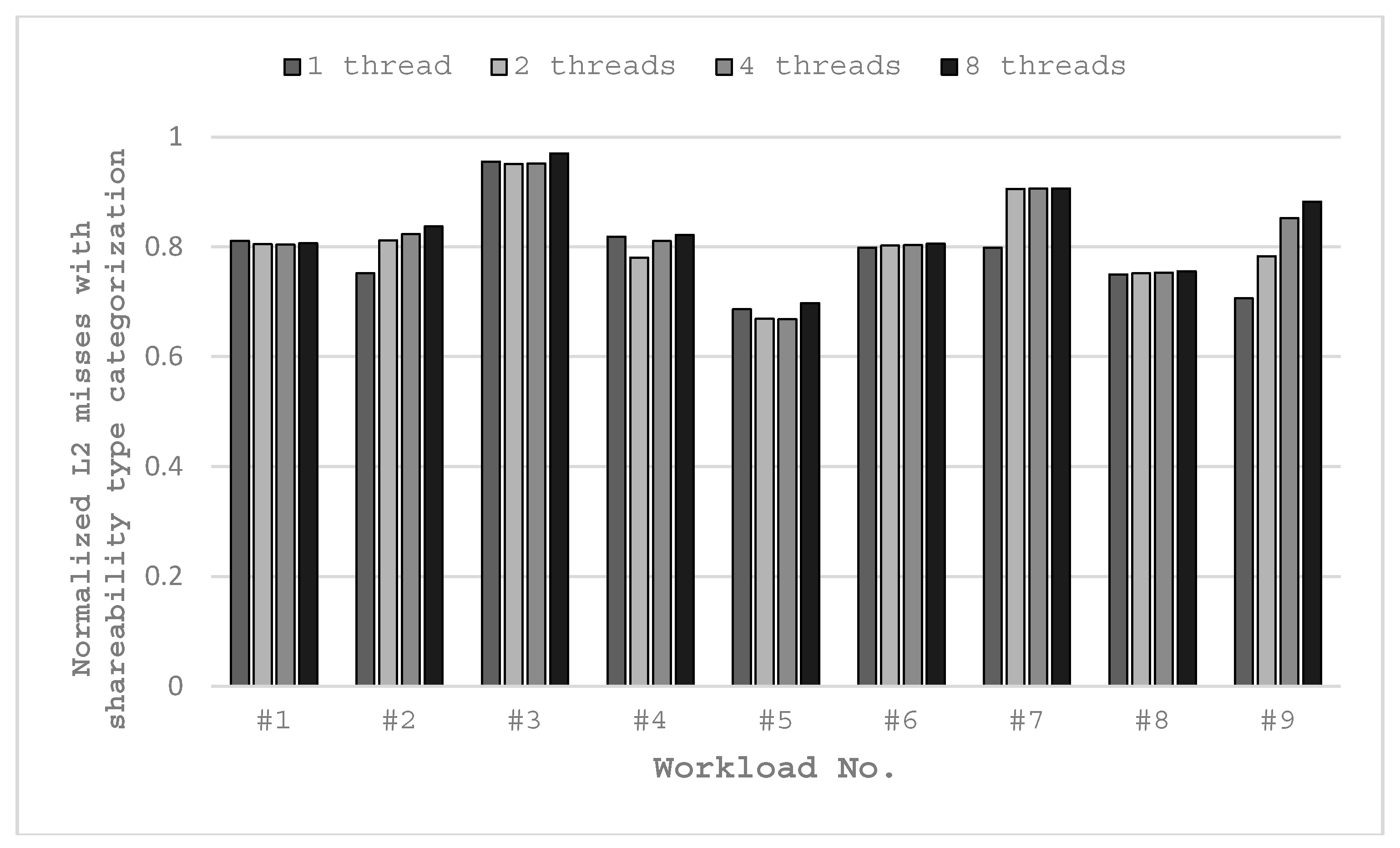
The workloads are executed in a quad-core platform. The experimental results in Figure 9 show that all the workloads running with shareability type categorization have fewer L2 misses compared to those without shareability type categorization, and this is due to the lesser memory boundness of the application. Table A1 in Appendix C presents the absolute numbers of L2 misses of 1/2/4/8 threads for the workloads listed in Table 5. Different WAPR settings are used for different numbers of threads (i.e., workers) and workloads.
Moreover, running in single-thread mode with shareability type categorization results in fewer L2 misses than the basic configuration. This is because we set all the instruction codes to private type and set all the program data to shared type for single-thread mode. Instructions and user data do not disturb each other, although only one thread is used. Most workloads have significant L2 miss reduction with shareability type categorization. The minimum reduction is 3.0% with 8-thread for #3 workload and the maximum reduction is 33.2% with 4-thread for #5 workload. For all workloads except for x264-4Mq, their lowest L2 misses are achieved with 2-thread or 4-thread. In some cases, more threads do not result in fewer L2 misses, such as #1 and #8 workloads. In some other cases, more threads result in more L2 misses, such as #7 and #9 workloads. The reason is that they have too many slices or streaming characters, then the degradation caused by the increased synchronization overrides the benefit of the increased number of threads.
6.3. Energy Consumption of ATCP
Next we evaluate the energy consumption of our ATCP in the quad-core system. In our experiments, we adopt the energy model in Reference [4] which is described in Section 2.3. Hardware related information can be obtained from the specifications. We capture the number of access, the number of miss and the number of execution cycles by running the workloads in the FPGA. As multi-thread and multi-task application should be tested, we use mix-mode workloads in EEMBC MultiBench which are listed in Table 6. Only 6 single-item workloads are in mix-mode and we combine them to construct the multi-item workloads.
For the multi-item workloads, when there are more items than cores, the items with longer execution time will not be scheduled until there are cores available. When the number of items is less than that of cores, some cores are not utilized. All the items in a workload start to work at the beginning and the shared cache is partitioned for them. But if any item is finished, the cache is repartitioned for the remaining executing items.
We evaluate the L2 cache energy consumption of our data adaptive thread-aware cache partitioning scheme (ATCP), by comparing it with three other cache partitioning schemes, that is, non-partitioned (LRU), core-based evenly partitioned (used in Reference [4], EVEN) and utility-based cache partition (in Reference [11], UCP). EVEN partitions a shared L2 cache evenly to all cores that each core occupies the same portion of the L2 cache. UCP in this work has minor modifications and we use UCP-M to represent it. The UCP-M algorithm is shown in the Matlab M-file format in Figure 10. We use a Threshold to avoid using extremely low utility cache ways.
The energy consumptions of the L2 cache with these cache partitioning schemes are shown in Figure 11 and Figure 12, in which Estatic stands for the leakage energy consumption (J) and Edynamic stands for the dynamic energy consumption (J). EVEN-2/ATCP-2 means EVEN/ATCP scheme in dual-core system and EVEN-4/ATCP-4 means EVEN/ATCP scheme in quad-core system. LRU/UCP-M partitioning scheme has no different results between dual-core and quad-core systems for single-item workloads, because it only cares about the current running tasks (items) and the number of cores. For multi-item workloads, there are differences between the occasion that items are more than cores and the occasion that items are less than cores. B11 and B12 have these differences and we use LRU-2/UCP-M-2 in dual-core system and LRU-4/UCP-M-4 in quad-core system.
For total energy consumption (Estatic plus Edynamic) in dual-core system: EVEN partitioning and UCP-M partitioning consume no more energy than LRU partitioning for single-item workloads. But EVEN may consume more energy than LRU for multi-item workloads (e.g., B7, B8). ATCP consumes the least energy for all the workloads, not only for single-item ones but also for the multi-item ones. EVEN uses fewer cache ways, so it consumes much less static energy compared with LRU. For most cases, EVEN performs better than LRU, especially when static energy dominates the total energy consumption (e.g., B1, B3). UCP-M benefits from both shutting down the low utility ways (in single-item workloads) and rearranging the idle cache ways for reuse (in multi-item workloads). ATCP also uses relatively small amount of cache ways for single-item workloads, so the static energy of ATCP is less than other schemes. Furthermore, ATCP reduces the interferences between different threads (multi-thread) and it also reduces the interferences between instruction codes and user data (single-thread). So less dynamic energy is consumed by cache misses, which is owed to multi-thread running and shareability type categorization in ATCP. For all workloads running in dual-core system, our ATCP scheme achieves 23.3%, 14.6% and 19.5% energy savings on average compared with LRU, UCP-M and EVEN. The maximum energy saving is 38.2% in B4, 25.3% in B1 and 32.3% in B7, compared with LRU, UCP-M and EVEN respectively.
The experimental results in quad-core system are similar to the results in dual-core system. Our ATCP scheme achieves 29.6%, 19.9% and 15.3% energy savings on average compared with LRU, UCP-M and EVEN. The maximum energy saving is 39.2% in B4, 35.9% in B1 and 23.4% in B9, compared with LRU, UCP-M and EVEN respectively. But there are some changes worthy of mentioning. First, ATCP-4 consumes no more energy than ATCP-2 for all the workloads. The reason is that ATCP-4 contains ATCP-2 in terms of scheduling the same workload. Second, EVEN-4 is not always better than EVEN-2 (e.g., B5). EVEN-4 uses fewer cache ways and consumes less static energy but more dynamic energy may be consumed because there are more cache misses. Third, UCP-M does not always outperform EVEN (e.g., B10 and B12) but it is never any worse than the performance of LRU.
6.4. Weight Speedup Performance of ATCP
We also evaluate the impact on execution time of our ATCP. We use normalized speedup to reflect the differences to the three-cache partitioning scheme. Speedup is 1/time and we normalize the speedup values to LRU. For LRU, EVEN and UCP-M, the execution time is measured in single thread. For ATCP, the execution time is the one when the best energy saving is achieved. All the experimental results are depicted in Figure 13.
For single-item workloads, EVEN takes more execution time than LRU as a result of using fewer cache ways. UCP-M has approximately the same results as EVEN in both dual-core and quad-core systems for single-item workloads. The differences of UCP-M and EVEN appear in multi-item workloads. EVEN has a degradation in speed with respect to LRU for most multi-item workloads. UCP-M shows speedup compared with LRU for most multi-item workloads. For our ATCP, it shows a great speedup for most workloads in both dual-core and quad-core systems. Maximum speedup arrives at 3.76 which is obtained in B4 in quad-core system, because it is executed with 4 threads. Average speedup is 1.6 for dual-core system and 1.89 for quad-core system. Single-item workloads speedup better than multi-item workloads in average in quad-core system, because they have a higher chance to be executed with more threads. When the number of items equals to the number of cores (e.g., B11 and B12), all items can run in parallel at the beginning, so multi-thread does not obtain much superior speedup compared with other cache partitioning schemes.
6.5. Hardware Overhead
TACM is the major hardware overhead of our ATCP. We use a similar cache monitor as UMON that Qureshi and so forth, proposed in Reference [11]. The differences are: (1) we count L2 accesses by thread ID rather than core ID; (2) we also use domain attribute when implementing ATDs and SCs. In our implementation, each ATD entry has 1-bit valid, 18-bit tag and 3-bit LRU, totally 22 bits. There are totally 32 sampled sets and 8 ATD entries per set. So an ATD requires 704 Bytes (22 bits/way × 8 ways/set × 32 sets) storage overhead. Another aspect, a SC group has 36 Bytes (9 counters × 4B/counter) overhead. We use private and shared domain ATDs and SCs for each core. Finally, for our quad-core, 1 MB L2 cache system, 5920 Bytes (2 × 4 × 740 Bytes) storage is required. Compared with total L2 cache’s 1108 K Bytes (84 KB tag + 1 M data) storage, only 0.52% hardware overhead is needed for TACM.
Replacement signs array (in Figure 8) is another major hardware overhead. To support cache partition in way aligned as Figure 5 shows, replacement block cannot distribute across different partitions. So, each partition region has its own replacement sign (i.e., LRU bits in ours). For the worst case, one sign is for one cache way and 21 bits (7 ways × 3 bits/way) are needed for one set. In our quad-core processor, 5376 Bytes (21 bits/set × 2048 sets) storage is needed, which is 0.47% of the total L2 cache.
In summary, less than 1% storage overhead is required for our ATCP in a quad-core processor. As for a dual-core processor, the overhead is even less, which is about 0.5%. For other resources, the domain bit is stored in MMU but it is only 1-bit hardware overhead. As for software aspect, the domain attribute is programmed with other page table information such as cacheable, writeable and virtual to physical address mapping, so no software overhead exists. WAPRs also require some storage, which is 64 bits in total for a quad-core processor. Other hardware overheads are some ‘AND’ and ‘MUX’ logic, which are negligible in area and timing.
7. Conclusions and Future Work
In this paper, we analyze the applications running in multi-thread mode and classify data of the multi-thread applications into different categories. Then an access adaptive and thread-aware cache partitioning (ATCP) scheme is proposed to avoid data conflicts of different categories in the shared cache. In ATCP, tasks can run in either multi-thread mode or single-thread mode, it can fully take the advantage of multi-threading to reduce the execution time. The cache ways of the shared L2 cache are allocated by thread IDs and shareability types (shared or private). ATCP achieves 23.3% and 14.6% average energy savings over LRU managed and utility-based (UCP-M) managed cache in the dual-core system. The results for the quad-core system are 29.6% and 19.9%. Maximum energy savings are up to 38.2% and 25.3% in the dual-core system, 39.2% and 35.9% in the quad-core system, respectively. Meanwhile, the execution time of the applications may be shortened. In our experimental results, the maximum speedup arrives at 3.76 in quad-core system and the average speedup is 1.89 in quad-core system and 1.6 in dual-core system with respect to the LRU managed shared cache. We also propose a hardware structure to support the cache partitioning scheme, with less than 1% storage overhead in a quad-core processor. We should note that our approach can tackle various kinds of applications and it can even be extended to deal with scheduling problems if the corresponding constraints are added in Section 5.
We use off-line ILP algorithm to find the optimum solution and cache partitioning settings currently. But there are connections between the best number of threads and the number of available cores and the size of cache portion is related to the number of portions and total data size. We are studying these problems in detail to design an adaptive online algorithm for cache partitioning. Instruction codes are set to pure private or pure shared now in our experiments and it is not automatically set for different applications. We will improve this for future work. Finally, domain attribute can be extended, more bits can distinguish more domain regions, rather than currently just one bit for shared and private.
Author Contributions
Conceptualization, K.H., K.W. and X.Z.; Methodology, K.H., K.W. and X.Z.; Software, K.W. and X.Z.; Validation, K.W. and X.Z.; Formal Analysis, K.H., K.W. and X.Z.; Investigation, K.W. and X.Z.; Resources, K.H., D.Z. and X.Y.; Data Curation, K.W. and X.Z.; Writing-Original Draft Preparation, K.W. and X.Z.; Writing-Review & Editing, K.H. and D.Z.; Supervision, K.H., D.Z. and X.Y.; Project Administration, K.H., D.Z. and X.Y.; Funding Acquisition, K.H., D.Z. and X.Y.
Funding
This research was funded by National Science and Technology Major Project grant number 2017ZX01030-102-002.
Acknowledgments
This research was supported by the grant 2017ZX01030-102-002 from the National Science and Technology Major Project.
Conflicts of Interest
The authors declare no conflict of interest.
Appendix A
The calculation process in Section 3.1 is shown as follows.
Appendix B
The algorithm implemented with AMPL [37] is shown below.
Figure A1.
Modeling ATCP stage-1 with AMPL language.


Appendix C
Table A1 presents the absolute numbers of L2 misses of 1/2/4/8 threads for the workloads with shareability type categorization listed in Table 5.

Table A1.
Absolute Numbers of L2 misses.
| 1 Thread | 2 Threads | 4 Threads | 8 Threads | |
|---|---|---|---|---|
| iDCT-4M | 559762 | 562259 | 561684 | 562798 |
| ippktcheck-4M | 457806 | 494438 | 501275 | 509947 |
| ipres-4M | 1194471 | 1188617 | 1189926 | 1212975 |
| md5-4M | 1069036 | 1067770 | 1068777 | 1069591 |
| rgbcmyk-4M | 1697595 | 1695523 | 1696440 | 1697729 |
| rotate-4Ms1 | 977084 | 981723 | 982958 | 985802 |
| rotate-4Ms64 | 976646 | 1107929 | 1108632 | 1108981 |
| rotate-color1Mp | 731586 | 733462 | 734911 | 737384 |
| x264-4Mq | 8192807 | 9079863 | 9884366 | 10235233 |
References
- 8th Gen Intel Core Processor Families. Available online: https://www.intel.com/content/www/us/en/products/docs/processors/core/8th-gen-core-family-datasheet-vol-1.html (accessed on 10 July 2018).
- AMD Ryzen 7 PRO 1700X Processor. Available online: https://www.amd.com/en/products/cpu/amd-ryzen-7-pro-1700x (accessed on 30 August 2018).
- Chen, G.; Huang, K.; Huang, J.; Knoll, A. Cache partitioning and scheduling for energy optimization of real-time MPSoCs. In Proceedings of the IEEE 24th International Conference on Application-Specific Systems, Architectures and Processors, Washington, DC, USA, 5–7 June 2013; pp. 35–41. [Google Scholar]
- Wang, W.; Mishra, P.; Ranka, S. Dynamic cache reconfiguration and partitioning for energy optimization in real-time multi-core systems. In Proceedings of the 48th ACM/EDAC/IEEE Design Automation Conference, New York, NY, USA, 5–9 June 2011; pp. 948–953. [Google Scholar]
- Reddy, R.; Petrov, P. Cache partitioning for energy-efficient and interference-free embedded multitasking. ACM Trans. Embed. Comput. Syst. 2010, 9, 1–35. [Google Scholar] [CrossRef]
- Wang, W.; Mishra, P.; Gordon-Ross, A. Dynamic cache reconfiguration for soft real-time systems. ACM Trans. Embed. Comput. Syst. 2012, 11, 1–31. [Google Scholar] [CrossRef]
- Zhang, C.J.; Vahid, F.; Najjar, W. A highly configurable cache for low energy embedded systems. ACM Trans. Embed. Comput. Syst. 2005, 4, 363–387. [Google Scholar] [CrossRef] [Green Version]
- Zhang, C.; Vahid, F.; Lysecky, R. A self-tuning cache architecture for embedded systems. ACM Trans. Embed. Comput. Syst. 2004, 3, 407–425. [Google Scholar] [CrossRef] [Green Version]
- Powell, M.; Yang, S.H.; Falsafi, B.; Roy, K.; Vijaykumar, T.N. Gated-Vdd: A circuit technique to reduce leakage in deep-submicron cache memories. In Proceedings of the 2000 International Symposium on Low Power Electronics and Design, Rapallo, Italy, 25–27 July 2000; pp. 90–95. [Google Scholar]
- Flautner, K.; Kim, N.S.; Martin, S.; Blaauw, D.; Mudge, T. Drowsy caches: Simple techniques for reducing leakage power. In Proceedings of the 29th Annual International Symposium on Computer Architecture, Anchorage, AK, USA, 25–29 May 2002; pp. 148–157. [Google Scholar]
- Qureshi, M.K.; Patt, Y.N. Utility-based cache partitioning: A low-overhead, high-performance, runtime mechanism to partition shared caches. In Proceedings of the 39th IEEE/ACM International Symposium on Microarchitecture, Orlando, FL, USA, 9–13 December 2006; pp. 423–432. [Google Scholar]
- Kim, S.; Chandra, D.; Yan, S. Fair Cache sharing and partitioning in a chip multiprocessor architecture. In Proceedings of the 13th International Conference on Parallel Architecture and Compilation Techniques, Antibes, Juan-les-Pins, France, 3 October 2004; pp. 111–122. [Google Scholar]
- Mancuso, R.; Dudko, R.; Betti, E.; Cesati, M.; Caccamo, M.; Pellizzoni, R. Real-time cache management framework for multi-core architectures. In Proceedings of the 19th Real-Time and Embedded Technology and Applications Symposium, Philadelphia, PA, USA, 9–11 April 2013; pp. 45–54. [Google Scholar]
- Suzuki, N.; Kim, H.; Niz, D.D.; Andersson, B.; Wrage, L.; Klein, M.; Rajkumar, R. Coordinated bank and cache coloring for temporal protection of memory accesses. In Proceedings of the 16th International Conference on Computational Science and Engineering, Sydney, Australia, 3–5 December 2013; pp. 685–692. [Google Scholar]
- Jaleel, A.; Hasenplaugh, W.; Qureshi, M.; Sebot, J.; Steely, S.; Emer, J. Adaptive insertion policies for managing shared caches. In Proceedings of the 2008 International Conference on Parallel Architectures and Compilation Techniques, Toronto, ON, Canada, 25–29 October 2008; pp. 208–219. [Google Scholar]
- Rolan, D.; Andrade, D.; Fraguela, B.B.; Doallo, R. A fine-grained thread-aware management policy for shared caches. Concurr. Comput. 2014, 26, 1355–1374. [Google Scholar] [CrossRef]
- Wu, J.; Sui, X.; Tang, Y.; Zhu, X.; Wang, J.; Chen, G. Cache management with partitioning-aware eviction and thread-aware insertion/promotion policy. In Proceedings of the International Symposium on Parallel and Distributed Processing with Applications, Taipei, Taiwan, 6–9 September 2010; pp. 374–381. [Google Scholar]
- Sundararajan, K.T.; Porpodas, V.; Jones, T.M.; Topham, N.P.; Franke, B. Cooperative partitioning: Energy-efficient cache partitioning for high-performance CMPs. In Proceedings of the IEEE International Symposium on High-Performance Computer Architecture, New Orleans, LA, USA, 25–29 February 2012; pp. 1–12. [Google Scholar]
- Cook, H.; Moreto, M.; Bird, S.; Dao, K.; Patterson, D.A.; Asanovic, K. A hardware evaluation of cache partitioning to improve utilization and energy-efficiency while preserving responsiveness. ACM Sigarch Comput. Archit. News 2013, 41, 308–319. [Google Scholar] [CrossRef]
- Poovey, J.A.; Conte, T.M.; Levy, M.; Gal-On, S. A benchmark characterization of the EEMBC benchmark suite. IEEE Micro 2009, 29, 1–29. [Google Scholar] [CrossRef]
- Bienia, C.; Kumar, S.; Singh, J.P.; Li, K. The PARSEC benchmark suite: Characterization and architectural implications. In Proceedings of the 2008 International Conference on Parallel Architectures and Compilation Techniques, Toronto, ON, Canada, 25–29 October 2008; pp. 72–81. [Google Scholar]
- Qureshi, M.K.; Jaleel, A.; Patt, Y.N.; Steely, S.C.; Emer, J. Adaptive insertion policies for high performance caching. ACM Sigarch Comput. Archit. News 2007, 35, 381–391. [Google Scholar] [CrossRef]
- Yu, C.; Petrov, P. Off-chip memory bandwidth minimization through cache partitioning for multi-core platforms. In Proceedings of the Design Automation Conference, Anaheim, CA, USA, 13–18 June 2010; pp. 132–137. [Google Scholar]
- Sanchez, D.; Kozyrakis, C. Vantage: Scalable and efficient fine-grain cache partitioning. In Proceedings of the 38th Annual International Symposium on Computer Architecture, San Jose, CA, USA, 4–8 June 2011; pp. 57–68. [Google Scholar]
- Zhou, M.; Du, Y.; Childers, B.; Melhem, R.; Mossé, D. Writeback-aware partitioning and replacement for last-level caches in phase change main memory systems. ACM Trans. Archit. Code Optim. 2012, 8, 1–21. [Google Scholar] [CrossRef]
- Xie, Y.; Loh, G.H. PIPP: Promotion/insertion pseudo-partitioning of multi-core shared caches. In Proceedings of the 36th Annual International Symposium on Computer Architecture, Austin, TX, USA, 20–24 June 2009; pp. 174–183. [Google Scholar]
- Kaseridis, D.; Iqbal, M.F.; John, L.K. Cache friendliness-aware management of shared last-level caches for high performance multi-core systems. IEEE Trans. Comput. 2014, 63, 874–887. [Google Scholar] [CrossRef]
- Mattson, R.L.; Gecsei, J.; Slutz, D.R.; Traiger, I.L. Evaluation techniques for storage hierarchies. IBM Syst. J. 1970, 9, 78–117. [Google Scholar] [CrossRef]
- Kaseridis, D.; Stuecheli, J.; Chen, J.; John, L.K. A bandwidth-aware memory-subsystem resource management using non-invasive resource profilers for large CMP systems. In Proceedings of the 16th International Symposium on High-Performance Computer Architecture, Bangalore, India, 9–14 January 2010; pp. 1–11. [Google Scholar] [CrossRef]
- Cascaval, C.; Padua, D.A. Estimating cache misses and locality using stack distances. In Proceedings of the 17th Annual International Conference on Supercomputing, San Francisco, CA, USA, 23–26 June 2003; pp. 150–159. [Google Scholar] [CrossRef]
- Wang, W.; Mishra, P. Leakage-aware energy minimization using dynamic voltage scaling and cache reconfiguration in real-time systems. In Proceedings of the 23rd International Conference on VLSI Design, Bangalore, India, 3–7 January 2010; pp. 357–362. [Google Scholar] [CrossRef]
- CACTI. Available online: www.hpl.hp.com/research/cacti (accessed on 11 July 2018).
- Hardavellas, N.; Ferdman, M.; Falsafi, B.; Ailamaki, A. Reactive NUCA: Near-optimal block placement and replication in distributed caches. In Proceedings of the 36th Annual International Symposium on Computer Architecture, Austin, TX, USA, 20–24 June 2009; pp. 184–195. [Google Scholar] [CrossRef]
- Raikin, S.; Gueron, S.; Sheaffer, G. Protecting Private Data from Cache Attacks. U.S. Patent US8516201B2, 20 August 2013. [Google Scholar]
- Linear Programming. Available online: https://en.wikipedia.org/wiki/Linear_programming (accessed on 11 July 2018).
- MultiBench. Available online: https://www.eembc.org/multibench/index.php (accessed on 11 July 2018).
- AMPL for Students. Available online: https://ampl.com/products/ampl/ampl-for-students/ (accessed on 11 July 2018).
- Huang, K.; Wang, K.; Zheng, D.D.; Jiang, X.W.; Zhang, X.M.; Yan, R.J.; Yan, X.L. Expected energy optimization for real-time multiprocessor SoCs running periodic tasks with uncertain execution time. IEEE Trans. Sustain. Comput. 2018, 3. [Google Scholar] [CrossRef]
- CK810 of C-SKY CPU. Available online: en.c-sky.com/solution/13415.htm (accessed on 11 July 2018).
- Chen, C.; Joshi, A.; Salminen, E. Profiling EEMBC MultiBench Programs in 64-core Machine. EEMBC MultiBench Profiling White Paper. 2013. Available online: https://www.vhdl.org/images/community/ocp/white-papers/chen_eembc_profiling_2013.pdf (accessed on 27 August 2018).
Figure 1.
Typical multicore architecture with L1 and L2 caches.
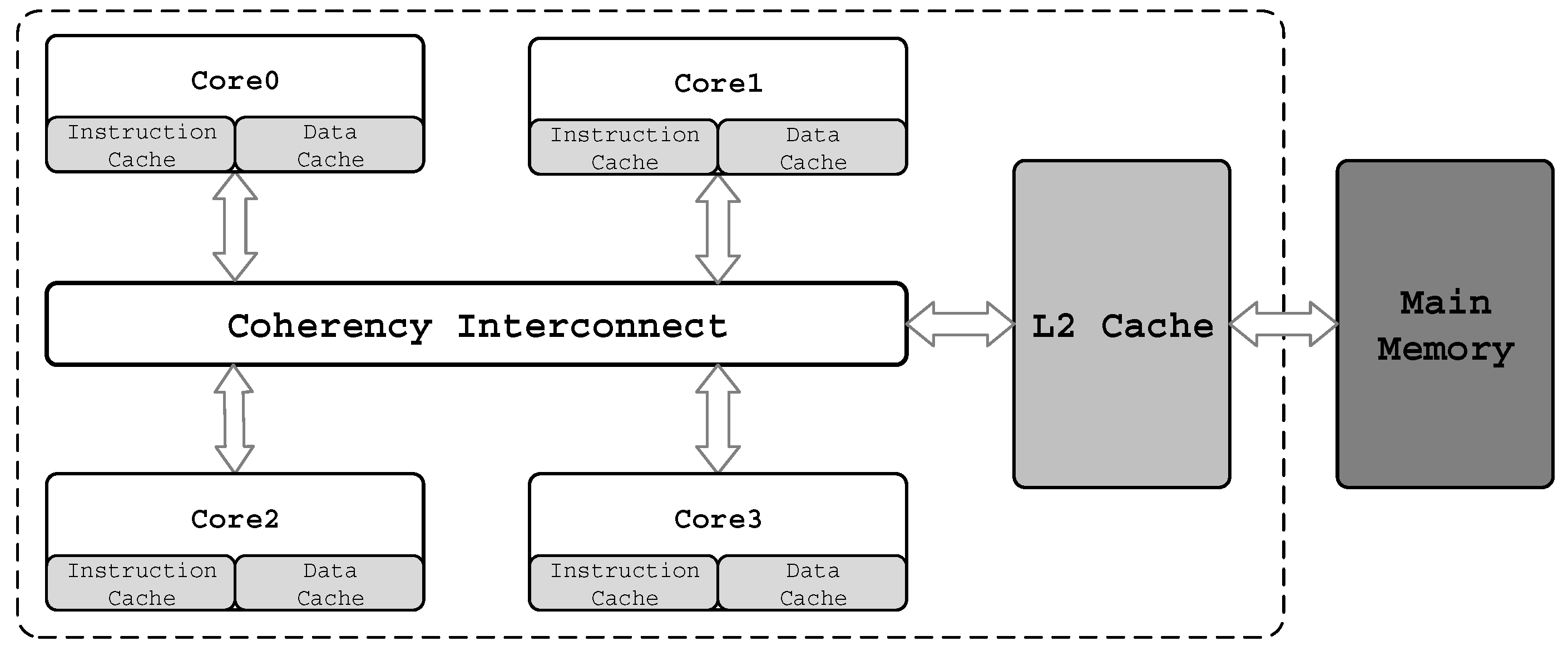
Figure 2.
LRU stack counters for monitoring.
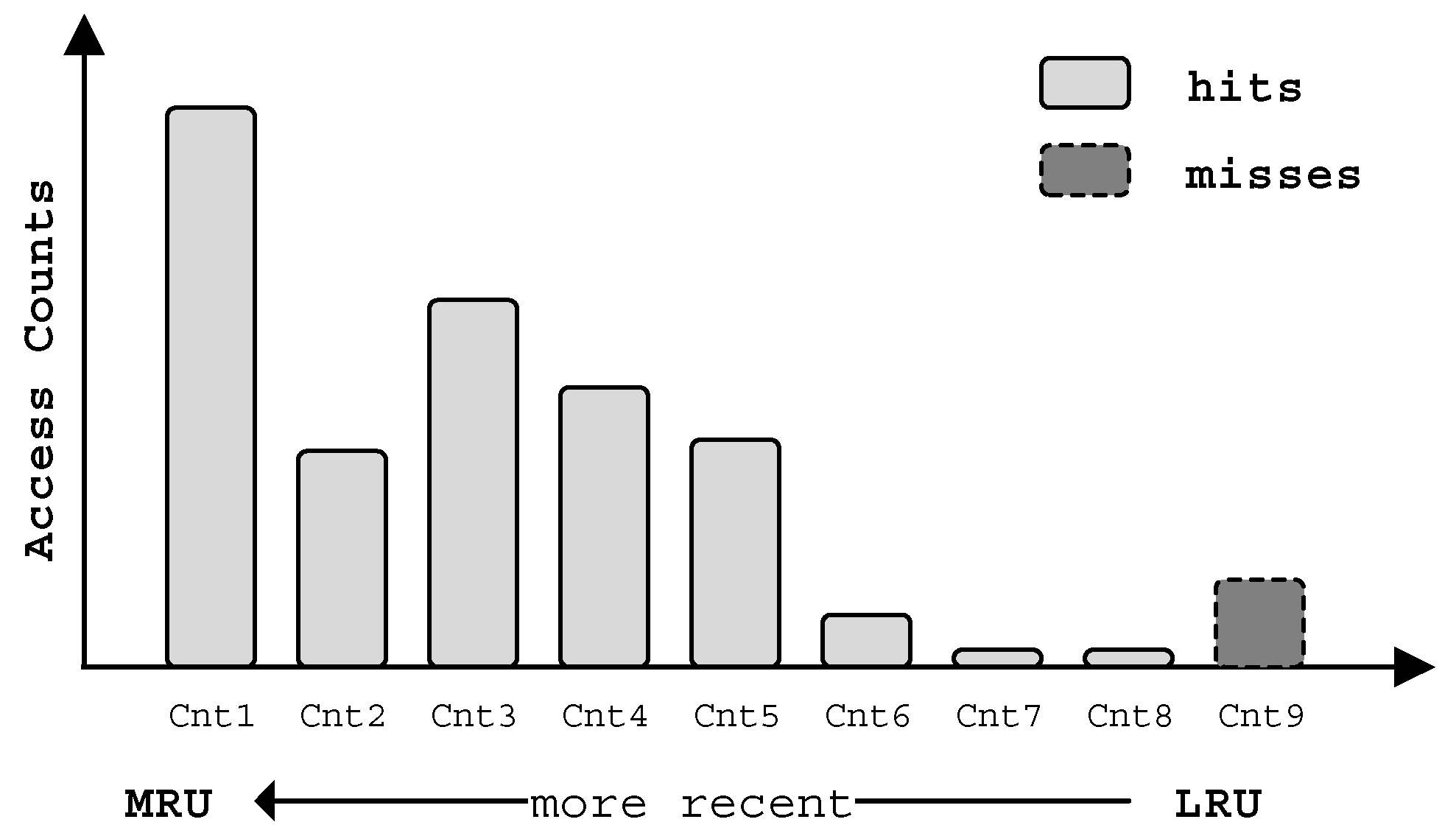
Figure 3.
Weighted speedup of parallel workloads with multi-thread with respect to single-thread.

Figure 4.
Scheduling in single-thread and multi-thread modes.

Figure 5.
Data placement in shared caches with different cache partitioning schemes. (a) Un-managed placement, (b) UCP placement, (c) Thread-aware placement.
Figure 5.
Data placement in shared caches with different cache partitioning schemes. (a) Un-managed placement, (b) UCP placement, (c) Thread-aware placement.
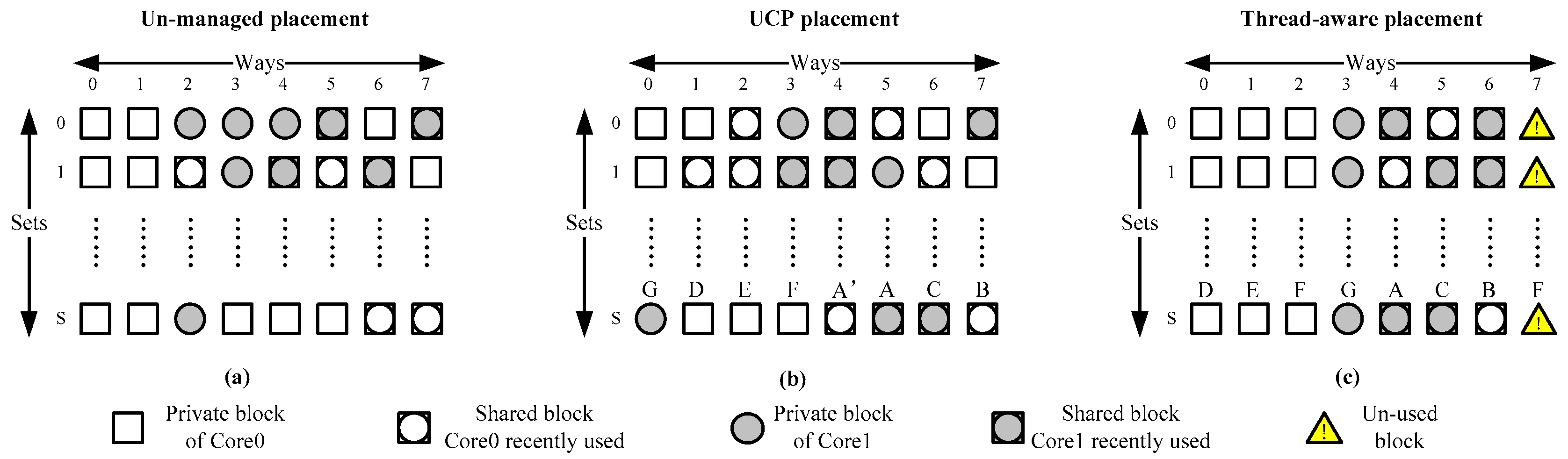
Figure 6.
Way access permission registers and way enable logic.

Figure 7.
An example of TACM architecture.

Figure 8.
ATCP scheme for multicore processor.
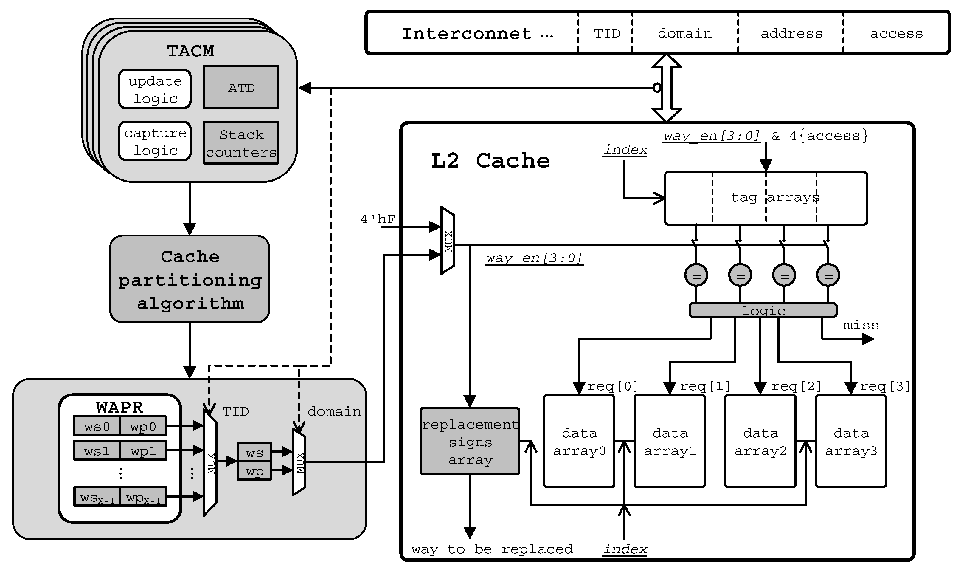
Figure 9.
Normalized total L2 misses of 1/2/4/8 threads running with shareability type categorization with respect to 1-thread running without shareability type categorization.
Figure 9.
Normalized total L2 misses of 1/2/4/8 threads running with shareability type categorization with respect to 1-thread running without shareability type categorization.

Figure 10.
Modified UCP algorithm.
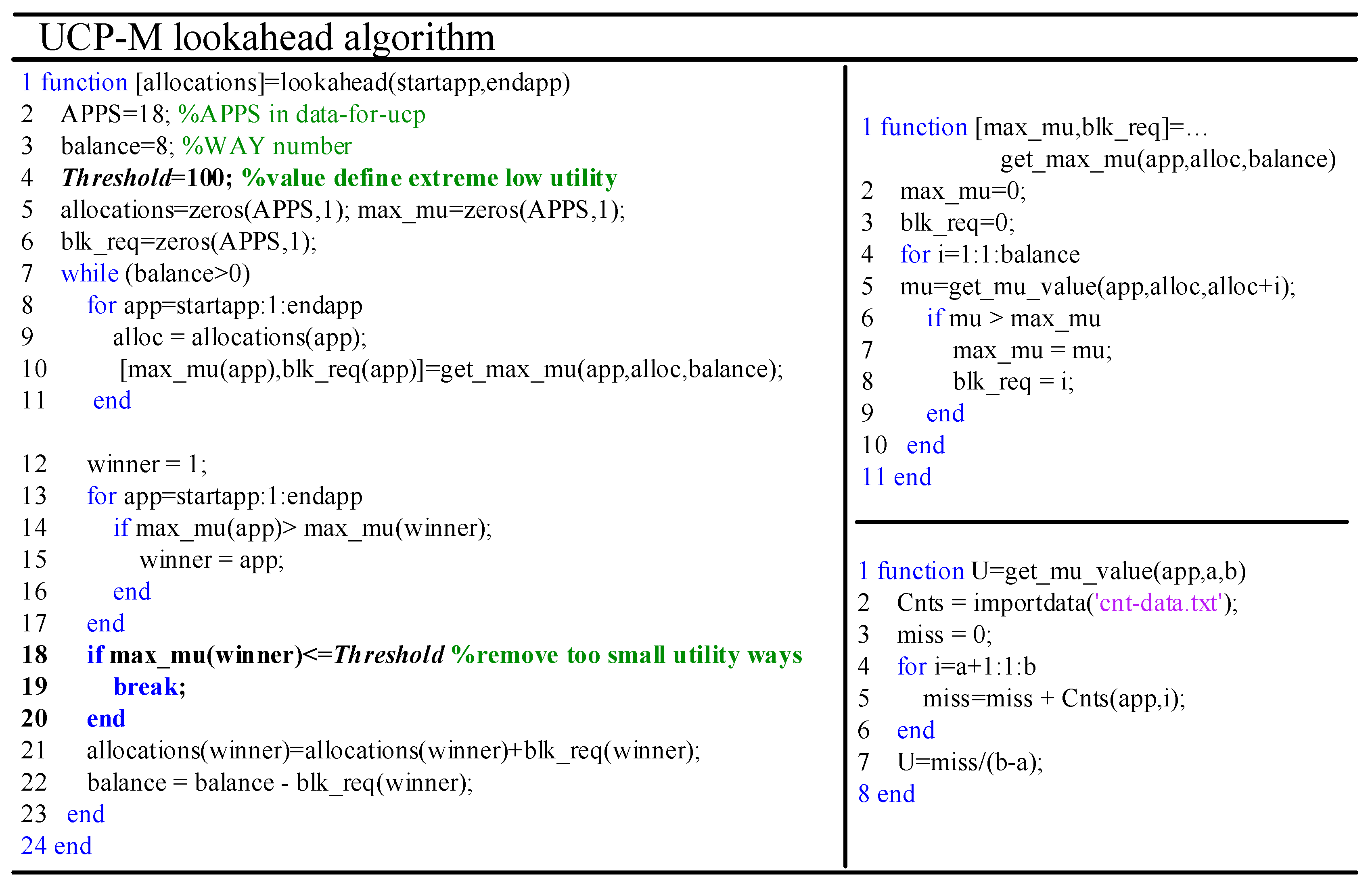
Figure 11.
Energy consumed by L2 for single-item mix-mode workloads.
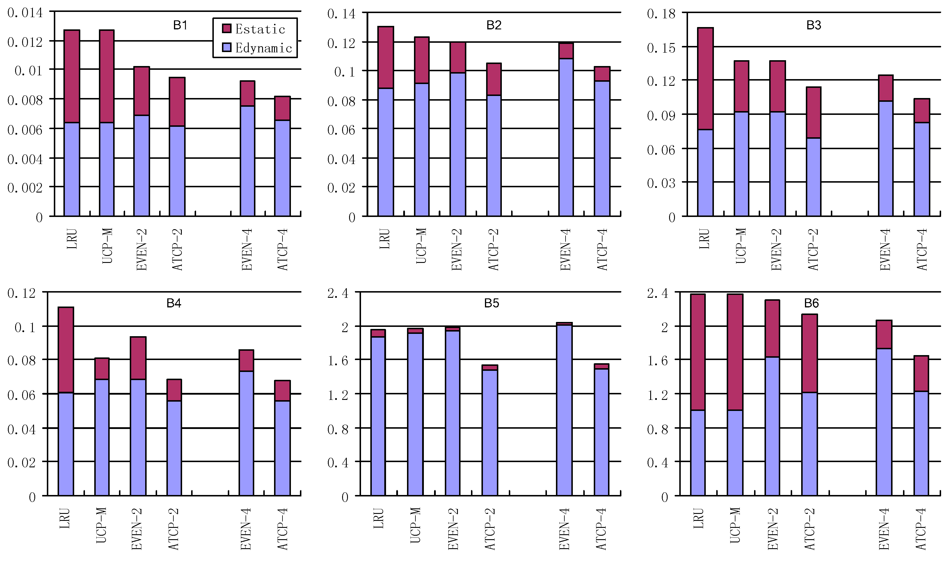
Figure 12.
Energy consumed by L2 for multi-item mix-mode workloads.
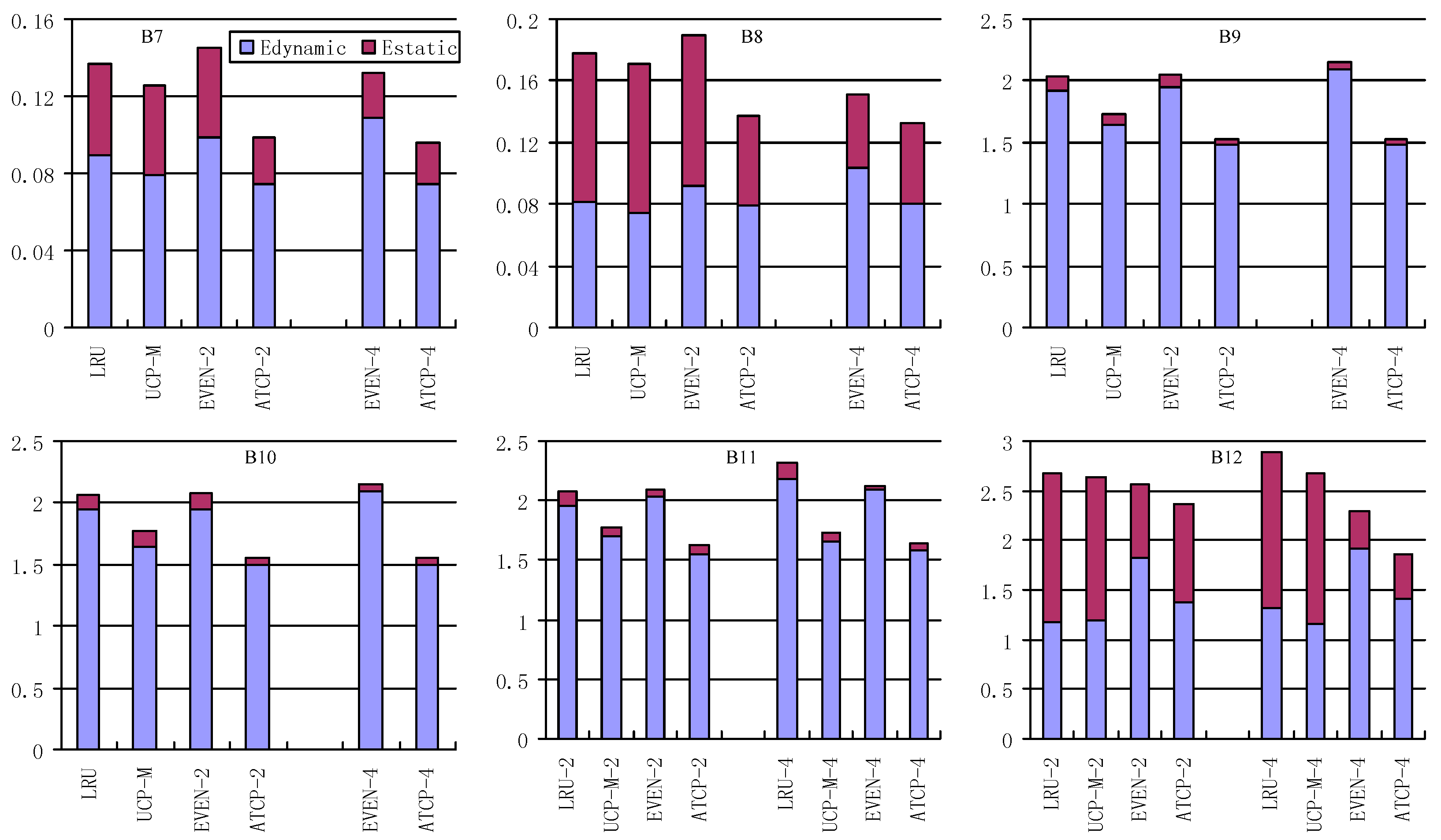
Figure 13.
Normalized speedup of various cache partitioning schemes. (a) Speedup in dual-core, (b) Speedup in quad-core.
Figure 13.
Normalized speedup of various cache partitioning schemes. (a) Speedup in dual-core, (b) Speedup in quad-core.
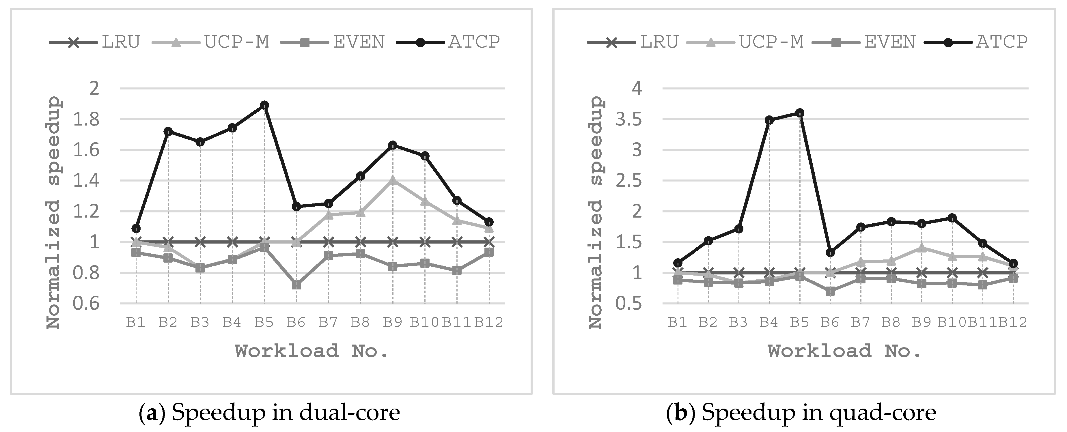
Table 1.
Variables and Constants of the MILP Problem for Stage-1.
| Partitioning Variables | |||
| Variable Name | Description | ||
| TH | number of threads of the given task | ||
| number of private ways for thread | |||
| number of shared ways for thread | |||
| Constant Values | Intermediate Variables | ||
| Constant Name | Description | Variable Name | Description |
| , , | power and energy constants for one cache way | , | static and dynamic energy for a thread with n ways |
| , | shared and private sub-monitor values for thread | , | numbers of cache access and miss for a thread with n ways |
| execution time for thread | energy of shared cache ways | ||
| M | number of cores | energy of private cache ways | |
| W | number of cache ways for the task | energy of the task | |
Table 2.
Variables and Constants of the MILP Problem for Stage-2.
| Partitioning Variables | |||
| Variable Name | Description | ||
| task t is assigned with W cache ways | |||
| Constant Values | Intermediate Variables | ||
| Constant Name | Description | Variable Name | Description |
| {E, S} | energy and settings of each task | total energy of all tasks | |
| N | number of ways of the shared cache | ||
| energy of task t with W cache ways | |||
Table 3.
Key Component Configurations on the FPGA Platform.
| Key Component | Configurations |
|---|---|
| Processor Core | 16-entry reorder buffer, 4 KB branch history table, 512-entry BTB |
| L1 cache | I-cache and D-cache, 32 KB total size, 32B cache line size, 4-way set-associative, FIFO replacement policy |
| L2 cache | 1 MB total size, 64B cache line size, 8-way set-associative, LRU replacement policy, way-based partition, 10 cycles for hit |
| Main Memory | 16 DRAM banks, about 400 CPU cycles L2 miss access penalty |
Table 4.
EEMBC Benchmark Kernel.
| Benchmark | Description |
|---|---|
| idctrn | Simulate an embedded automotive/industrial application performing digital video and graphics applications such as image recognition |
| rgbcmyk | Benchmark for digital image processing performance in printers and other digital imaging products |
| md5test | Calculate the MD5 checksum over multiple input buffers |
| ipres | Measure a processor’s performance in reconstructing the disjointed IP packages |
| ippktcheck | Model a subset of the IP header validation work |
| tcp | Designed to reflect the performance in three different network scenarios: TCP Jumbo, TCP Bulk and TCP Mixed |
| rotate | Rotate a binary image (greyscale or color) of arbitrary size by 90/180/270 degrees |
| x264 | A porting of x264 open source coder |
Table 5.
EEMBC parallel-mode workloads.
| No. | Workload | Description |
|---|---|---|
| 1 | iDCT-4M | Inverse discrete cosine transform, 4 MB buffer size |
| 2 | ippktcheck-4M | Check IP packet headers over 4 MB of data |
| 3 | ipres-4M | Send 4 greyscale images to a printer over the network |
| 4 | md5-4M | Message-digest checksum used in cryptography, 4MB buffer size |
| 5 | rgbcmyk-4M | Convert RGB to CMYK color |
| 6 | rotate-4Ms1 | Rotate grayscale images by 90 degrees, image size is 4 MB, 1 slice |
| 7 | rotate-4Ms64 | Rotate grayscale images by 90 degrees, image size is 4 MB, 64 slices |
| 8 | rotate-color1Mp | Rotate 1M Pixel color image by 90 degrees |
| 9 | x264-4Mq | Encode a stream of image in YUV format to H.264 main profile |
Table 6.
EEMBC mix-mode workloads.
| Name | Items | Name | Items |
|---|---|---|---|
| B1 | 4M-check | B7 | B1+B2 |
| B2 | 4M-reassembly | B8 | B1+B3 |
| B3 | 4M-tcp-mixed | B9 | B4+B5 |
| B4 | 4M-cmykw2 | B10 | B5+B3 |
| B5 | 4M-rotatew2 | B11 | B1+B2+B4+B5 |
| B6 | 4M-x264w2 | B12 | B1+B2+B3+B6 |
© 2018 by the authors. Licensee MDPI, Basel, Switzerland. This article is an open access article distributed under the terms and conditions of the Creative Commons Attribution (CC BY) license (http://creativecommons.org/licenses/by/4.0/).
Share and Cite
MDPI and ACS Style
Huang, K.; Wang, K.; Zheng, D.; Zhang, X.; Yan, X. Access Adaptive and Thread-Aware Cache Partitioning in Multicore Systems. Electronics 2018, 7, 172. https://doi.org/10.3390/electronics7090172
AMA Style
Huang K, Wang K, Zheng D, Zhang X, Yan X. Access Adaptive and Thread-Aware Cache Partitioning in Multicore Systems. Electronics. 2018; 7(9):172. https://doi.org/10.3390/electronics7090172
Chicago/Turabian StyleHuang, Kai, Ke Wang, Dandan Zheng, Xiaoxu Zhang, and Xiaolang Yan. 2018. "Access Adaptive and Thread-Aware Cache Partitioning in Multicore Systems" Electronics 7, no. 9: 172. https://doi.org/10.3390/electronics7090172
Note that from the first issue of 2016, this journal uses article numbers instead of page numbers. See further details here.