A Hierarchical Vision-Based UAV Localization for an Open Landing
by
 , ,
, ,
Haiwen Yuan
1,2,* ,
,
Changshi Xiao
1,3,4,*,
Supu Xiu
1,
Wenqiang Zhan
1,
Zhenyi Ye
2,
Fan Zhang
1,3,4,
Chunhui Zhou
1,3,4,
Yuanqiao Wen
1,3,4 and
Qiliang Li
2,* 1
School of Navigation, Wuhan University of Technology, Wuhan 430063, China
2
Department of Electrical and Computer Engineering, George Mason University, Fairfax, VA 22030, USA
3
Hubei Key Laboratory of Inland Shipping Technology, Wuhan University of Technology, Wuhan 430063, China
4
National Engineering Research Center for Water Transport Safety, Wuhan University of Technology, Wuhan 430063, China
*
Authors to whom correspondence should be addressed.
Electronics 2018, 7(5), 68; https://doi.org/10.3390/electronics7050068
Submission received: 11 April 2018
/
Revised: 5 May 2018
/
Accepted: 9 May 2018
/
Published: 11 May 2018
(This article belongs to the Special Issue Nanoelectronic Materials, Devices and Modeling)
Abstract
:The localization of unmanned aerial vehicles (UAVs) for autonomous landing is challenging because the relative positions of the landing objects are almost inaccessible and the objects have nearly no transmission with UAVs. In this paper, a hierarchical vision-based localization framework for rotor UAVs is proposed for an open landing. In such a hierarchical framework, the landing is defined into three phases: “Approaching”, “Adjustment”, and “Touchdown”. Object features at different scales can be extracted from a designed Robust and Quick Response Landing Pattern (RQRLP) and the corresponding detection and localization methods are introduced for the three phases. Then a federated Extended Kalman Filter (EKF) structure is costumed and utilizes the solutions of the three phases as independent measurements to estimate the pose of the vehicle. The framework can be used to integrate the vision solutions and enables the estimation to be smooth and robust. In the end, several typical field experiments have been carried out to verify the proposed hierarchical vision framework. It can be seen that a wider localization range can be extended by the proposed framework while the precision is ensured.
1. Introduction
Unmanned aerial vehicles (UAVs) are popular among civil and military situations that are hazardous to human operators. Automated localization is therefore highly desirable while the vehicles are required to land on stationary or moving platforms. Therefore, a real-time relative localization is desirable, which refers to the ability to localize themselves relying on onboard sensors, such as Global Positioning System (GPS), Inertial Measurement Unit (IMU), vision, lidar, etc. Currently the GPS, IMU or their combination is the most common method used to determine the pose of a UAV. However, these require the transmission of information between the air vehicle and the landing platform. The use of vision sensors for localization has many advantages. As one low-cost sensor vision is mostly passive and does not rely on an external signal. It is worth noting that vision can have millimeter-level accuracy and can determine not only the distance but also the relative orientation between two objects. This paper describes a vision-based localization framework and the key enabling technologies for an open landing.
In recent years, there has been a wealth of research and various vision-based methods available for UAV landing. These include both feature-based methods and direct methods. Some of the approaches require prior knowledge of the targets and others extract information from the surroundings in real time. These vision-based methods work with a good localization precision but are limited by the detection range. Especially, UAVs can hardly extract constant pose features from landing objects as the relative distance increases or decreases. To solve this problem, a hierarchical vision-based localization strategy is designed to extract reliable visual features at different scales in this paper.
It is noted that open landing refers to a complete decline process from a high altitude to touchdown, which normally requires a wide localization range. For this purpose, this paper describes a hierarchical vision-based UAV localization demonstration in which the pose (position and orientation) can be estimated by using the onboard camera. A Robust and Quick Response Landing Pattern (RQRLP) is designed for the hierarchical vision detection. The RQRLP is able to provide various scaled visual features for UAV localization. In detail, for an open landing, three phases—“Approaching”, “Adjustment”, and “Touchdown”—are defined in the hierarchical framework. First, in the “Approaching” phase the UAV is relatively far from the vessel and the contour of the RQRLP is detected and used as the main visual feature. Second, as the UAV approaches the landing object, detailed location markers can be extracted from the RQRLP. This phase is called “Adjustment” and the aerial vehicle can calculate the current pose with respect to the RQRLP with a high precision and adjusts its pose for the touchdown. In the final “Touchdown” phase, the UAV is so close to the vessel that the location markers are almost out of the field of view (FOV). As one alternative solution, an optic-flow based tracker is employed to calculate the current pose by tracking the previous one until the touchdown. To obtain a robust localization estimation, the three phases work in parallel as nodes. A federated filter based on the Extended Kalman Filter (EKF) is costumed to integrate these vision solutions. In the end, the proposed framework is tested and verified by several field experiments and results, which illustrate its performance.
The remainder of the paper is organized as follows. In Section 2, some related work is introduced. In Section 3, the design of the RQRLP is described as the landing object in the hierarchical vision localization framework and provides visual information for the UAV pose calculation. Section 4 introduces a hierarchical vision-based localization framework, which enables the three phases and integrates the UAV pose. Section 5 presents the experiments and results to verify and illustrate our proposed hierarchical vision-based framework. Finally, the conclusions are presented in Section 6.
2. Previous Work
Currently, vision-based localization is one of the most-adopted ways to actively study UAV autonomous landing. In general, for a spot landing, such as landing on a moving vehicle, UAVs with onboard cameras are able to calculate the pose by recognizing a referenced object [1]. In these related works, it is assumed that the image pattern and size of the referenced object are known in advance. The relative localization can be acquired by analyzing the projection image. For example, depending on the inertia moments of the image, the landing object could be distinguished from the background [2]. The UAV orientation is calculated by matching real-time images with a stored dataset of labeled images that have been calibrated offline. Due to image blurring, the cooperative feature points cannot be accurately extracted from the images. As one solution, a special pattern consisting of several concentric white rings on a black background was designed as a landing object [3]. Each of the white rings is recognized by a unique ratio of its inner to outer border radius. However, only the height with respect to the landing platform is provided by this method. Based on the feature lines of the cooperative object, a pose estimation algorithm was reported in [4]. In the algorithm, feature lines and vanishing lines were extracted to reduce the influence of image blurring. An initial 5 Degree-Of-Freedom (DOF) pose with respect to a landing pad was obtained by calculating the quadratic equation of the projected ellipse [5]. The IMU data was integrated to eliminate the remaining geometric ambiguity. The remaining one DOF of the camera pose, the yaw angle, was calculated by fitting an ellipse to the projected contour of the letter “H”. The homography between the image frame and the object reference plane was also used to estimate the UAV initial pose [6]. With four correspondences between the world plane and the image plane, a minimal solution of the homography was estimated. A similar work was also reported in [7], where the homography between current and previous frames was decomposed and accumulated for ego-motion estimation. Moreover, the relative pose between current and previous frames could be estimated by tracking a structured-unknown object [8,9,10]. Similar to the dead reckoning of an inertial navigation system (INS), these type methods would suffer from signal drift as time elapsed.
In another case, it is assumed that the reference object for UAV landing and localization is unknown. Optical flow is the typical method and it is used to track or stabilize the UAV pose [11,12,13,14,15,16]. A biological guidance system was reported in [17], where some cues from the natural environment were detected and analyzed, such as the horizon profile and sky compass. An image Coordinates Extrapolation (ICE) algorithm [18] calculated the pixel-wise difference between the current view (panoramic image) and a snapshot taken at a reference location to estimate the real-time UAV 3D position and velocity. An optic flow-based vision system is reported in [19,20], where the optic flow was calculated and used for autonomous localization and scene mapping. Relevant control strategies using vision information are also discussed in detail. The combination of the vision and IMU data reported in [21,22] assumed that the IMU had the ability to provide a good roll and pitch attitude estimation, and four infrared spots on the target or the landing spot could be detected using the vision system. In addition, stereo vision using triangulation has been applied during a UAV autonomous landing [23,24].
Following the works described above, it is therefore expected that feature detection and recognition would be a key issue with regard to localization precision. In addition, for an open landing, such as in the wilderness or maritime environment, the UAV must have the ability to process the detection problem in a wide and consecutive working range. For this purpose, a hierarchical detection and localization framework is proposed and studied to detect and extract various scale features from the landing object. In one of our preliminary works, a UAV autonomous visual navigation system was reported in [25].
3. Feature Recognition and Pose Recovery
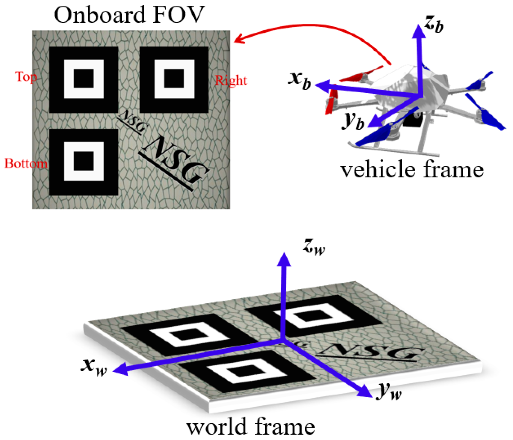
The UAV localization for automatic landing is a complex but solvable problem that can be achieved by the means of vision. In this section, the RQRLP as a reference object is designed for UAV vision and consists of a set of friendly artificial location markers, shown in Figure 1. By detecting and recognizing the RQRLP, the UAV can estimate its pose at different heights. The corresponding detection and pose recovery algorithm, based on homography decomposition, is also introduced in this section.
3.1. The RQRLP as Landing Object
A vision-based localization is any one that makes use of visual information. The visual information can be used for navigation, vehicle stabilization, vehicle guidance, obstacle avoidance, or target tracking.
The visual feature at several scales can be provided by the designed landing object RQRLP. A series of structured and non-structured graphs are set in the RQRLP. The structured graphs comprised of several nested rectangles are used to provide the scale information for pose calculation, while the non-structured ones are good feature points for pose tracking. Considering the QR (Quick Response) code popularly applied in the field of current information recognition, each set of nested rectangles is regarded as the location markers Top, Right, and Bottom, respectively. These location markers can be detected and recognized robustly by contour extraction and statistics. First, since each location marker has a constant contour number, they can be extracted from the background using contour detection and statistics. Second, the “Top” marker is distinguished by calculating the straight-line distances between any two markers and is the one that is not on the longest line. Third, the “Right” and “Bottom” location markers are also recognized by calculating the slope of the longest line and the distance from the “Top” marker to the longest line. So far, these location markers are recognized uniquely. Assuming that the size of these markers is known, enough corners of the markers can be obtained as the corresponding information between the RQRLP and its image plane. The corresponding points are used for recovering the 6-DOF pose of the UAV. Except for the structured markers, random texture is designed as the background and consists of rich traceable feature points. The use of such a RQRLP mode can reduce algorithm complexity and run-time, and allows relative poses to be measured when the onboard camera system has been correctly calibrated.
3.2. Pose Recovery Based on Image Homography
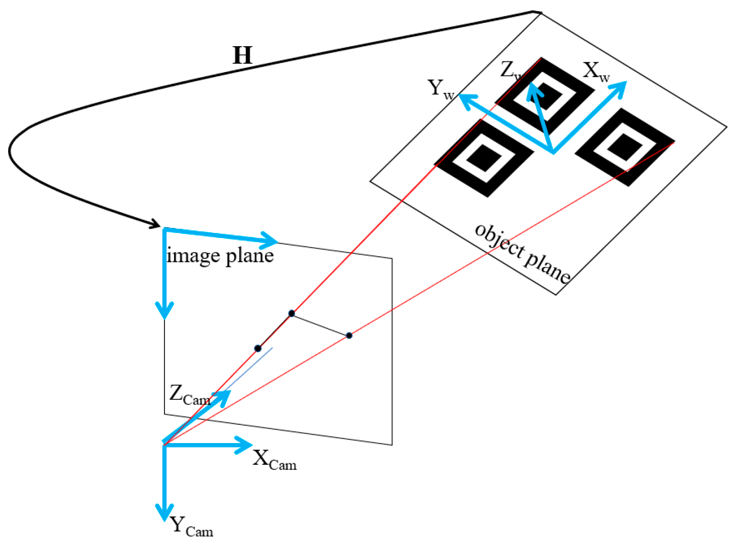
The 6-DOF pose of a UAV (position and orientation) can be recovered by homography decomposition. Here, homography is a non-singular 3 3 matrix that defines the projection between the RQRLP and its image plane, and can be calculated using the acquired corresponding points. Assuming that the 3D coordinate system is built on the RQRLP plane, the Z-axis of all the extracted points are zeros. As a result, the 3D coordinates of all points on the RQRLP are defined to be . And the corresponding image points are , the homography relation can be described as follows,
Using the extracted corresponding points, one rough solution about the matrix can be obtained by Singular Value Decomposition (SVD) [26] or Gaussian Eliminate (GE) [27]. Then, using the Random Sample Consensus (RANSAC) method, the matrix can be optimized to remove the errors from the mismatched points. The goal is achieved after iteratively selecting a random subset of the original data points by testing it to obtain the model and evaluating the model consensus, which is the total number of original data points that best fit the model.
As shown in Figure 2, the matrix can be decomposed to require the onboard camera pose with respect to the RQRLP, since the homography contains the information of the camera intrinsic and extrinsic parameters. As shown in Equation (1), assuming that the camera parameter matrix is known, the 3 3 rotation matrix and the 3 1 translation vector are involved in the remaining part and can be calculated based on the camera projection model [26],
where the 3 1 vector is the i-th column of and the 3 1 vector is the i-th column of . Since all the columns of the rotation matrix are orthonormal to each other, can be determined from . However, the data noise causes the resulting matrix to not satisfy the orthonormality condition, and SVD is used to form a new optimal rotation matrix that is fully orthonormal.
With this, , represents the position and the orientation of the onboard camera in the 3D coordinate system of the RQRLP. As a result, the UAV’s pose can also be determined since the camera is fixed on the body.
4. A Hierarchical Vision-Based Localization Framework
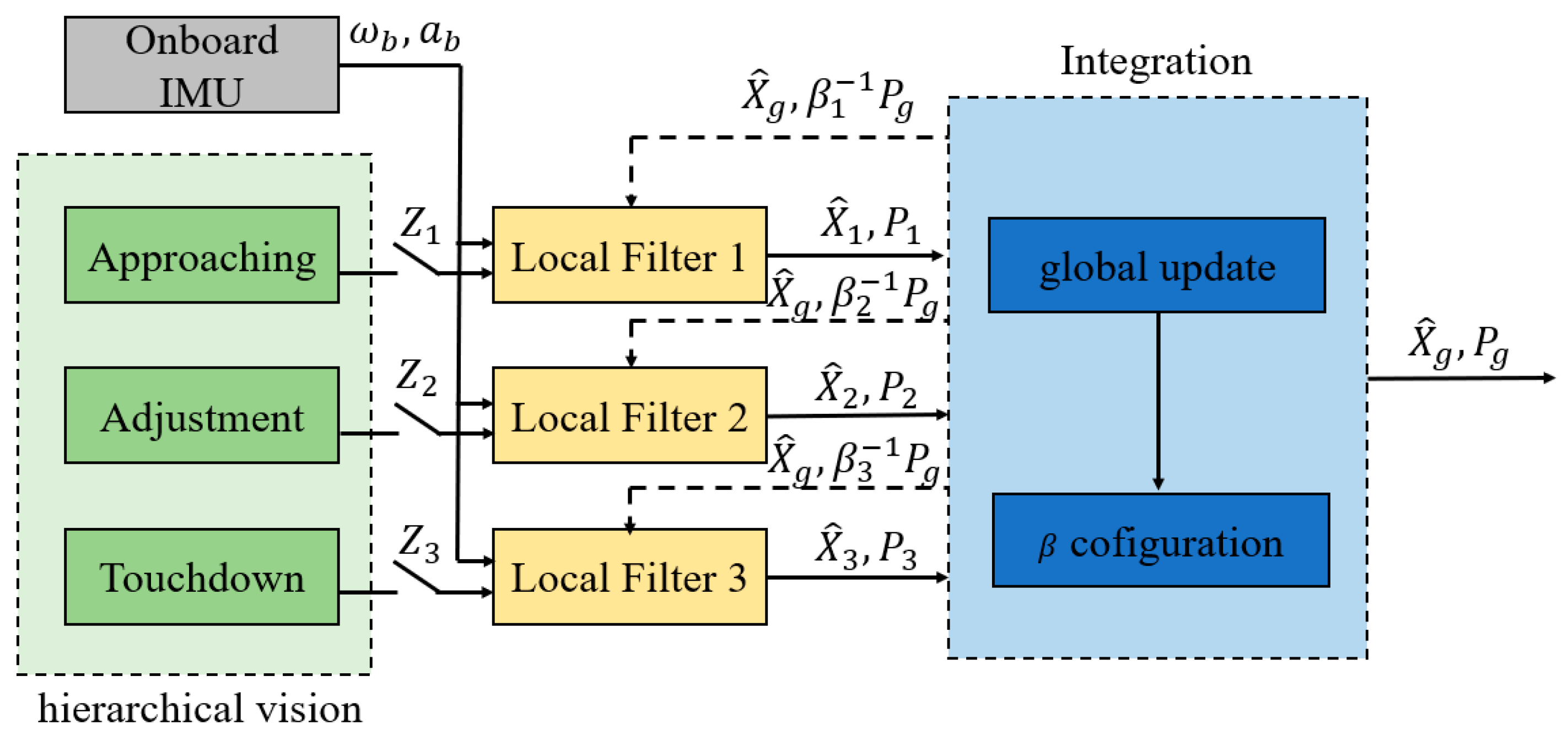
Except for the algorithm of object detection and pose recovery, as the limited image resolution and the fixed focal-length the employed vision system would have an effect on localization precision specially when the UAV is at different height. To solve the problem, a hierarchical vision-based localization framework is proposed, which can extract different scaled features for the corresponding detection phases, as shown in Figure 3. In this section, how to achieve a vision solution for the three phases and how to achieve the UAV pose by integrating the pose solutions is described.
4.1. Hierarchical Localization
Considering an open landing, there are three phases—“Approaching”, “Adjustment”, and “Touchdown”—defined in the hierarchical framework. A different vision solution is employed in each phase.
At the beginning, the UAV is remote from the landing object RQRLP so that it cannot see the details of the RQRLP clearly. At this point, the outline and dimensions of the RQRLP are detected by the onboard vision system. Hence, a simple matching-based method is used to find the landing object from the scene. By tracking the four corners from the rectangular landing object, it is possible to calculate the relative pose of the UAV. But since the localization is rough, only the 3D position remains for guiding the vehicle towards the landing. By detecting and tracking the visual information, it is thought that the UAV can approach the RQRLP and more vision details can be acquired. This phase is therefore called “Approaching”. In detail, the image dimensions and coordinates of the RQRLP are used to provide the relative 3D position for the UAV movement. It is noted that the image projection of an object implies the relative distance between current view and the object when the camera parameters are fixed.
For the next “Adjustment” phase of the landing, it is assumed that the flying vehicle is sufficiently close to the RQRLP so that the detail of the RQRLP can be detected as the visual information for localization. Using image corners from the location markers of the RQRLP, the relative position and orientation of the UAV can be calculated exactly by the pose recovery method presented in the previous section. As a result, a 6-DOF pose of the UAV can be acquired in the “Adjustment” phase. The obtained real-time pose is used to adjust the UAV to an appropriate state for landing. In particular, the movement of a landing object (surface or ground vehicle) can be also observed when the UAV is hovering over the object.
When the UAV is near the end of a landing, the view of the onboard vision system is limited and the image of the RQRLP can only be captured in part. This phase is called “Touchdown” in our work. Either one of the two visual features for the last two phases is out of work in this phase, and an optical flow-based pose tracker is designed to infer the current pose by calculating the optic-flow between current and previous image frames. Rich textures distributed in the RQRLP can provide vast traceable feature points. In detail, these points from the planer RQRLP are matched successfully by a nearest neighbor method and the matched point-pairs are used to calculate the homography between current frame and last frame . Then, the UAV 6-DOF pose at the current time can be obtained by Equation (3). Such a pose tracking method is feasible as certain good corners in the RQRLP enable convenient tracking and the process is sufficiently short that accumulative error is negligible.
The visual information at different scales are detected in three defined landing phases for UAV localization with respect to the RQRLP. All of the vision-based feature detection and pose calculations constitute a hierarchical localization framework. The framework is practical and can guarantee a consecutive pose solution for a UAV relative landing, such as landing on a maritime vehicle.
4.2. Pose Integration
It should be noted that vision-based solutions for the three landing phases are not strictly separated and no less than one solution can be acquired during overlapping. To obtain an optimal localization by integrating these solutions, a federated filter that involves only three local filters is customized. The federated filter enables the final estimated localization to be consecutive and smooth.
The total structure of the customized federated filter is described in Figure 4. Three local filters are customized for the three vision solutions, , and , respectively. Each local filter is a typical extended Kalman filter that involves prediction and update modules, and takes the localization solution from the vision nodes as the measurement input. The integration part is in charge of calculating the optimal pose solution and the allocation coefficient . Moreover, an Inertial Measurement Unit (IMU) is used as the reference system of the federated filter and provides real-time angular velocities and accelerations for the UAV state prediction. In detail, the estimated state of each local filter is a 7-dimensional vector, which involves the UAV position and orientation, as in Equation (4). In such a local filter, the state is predicted by the IMU, and then is updated by the visual measurement. As is known from the above, the measurements from the three phases are absolute or relative pose, as shown in Equation (5),
Acquired from these local filters, these estimated state with the corresponding covariance that is a 7 7 matrix, are passed to the integration module. It is noted that the covariance can imply the performance of the filter , which means the current detection or measurement precision for the vision node can be reflected by . By summing all available weighted with the corresponding covariances from the local filters, the global process noise , state variance and state are calculated as Equations (6)–(8),
In addition, it is necessary for a federated filter to introduce a coefficient (), which can be used to allocate the prediction noise and the state covariance for the local filters at next time. In general, is fixed for a typical Carlson federated filter. However, the detection precision of the vision measurements is changing for different landing phases. Thus the allocation coefficient should also be set to dynamical. As a result, is defined to be related with , and the calculation is shown in Equation (9). It can be thought that is inversely proportional to . By such a dynamical allocation, some disastrous influence could be reduced to output on other filters while one measurement of the vision localizations is out of work or unreliable. At the same time, the recovery capability for the failed filter can be also enhanced.
5. Field Experiments and Results
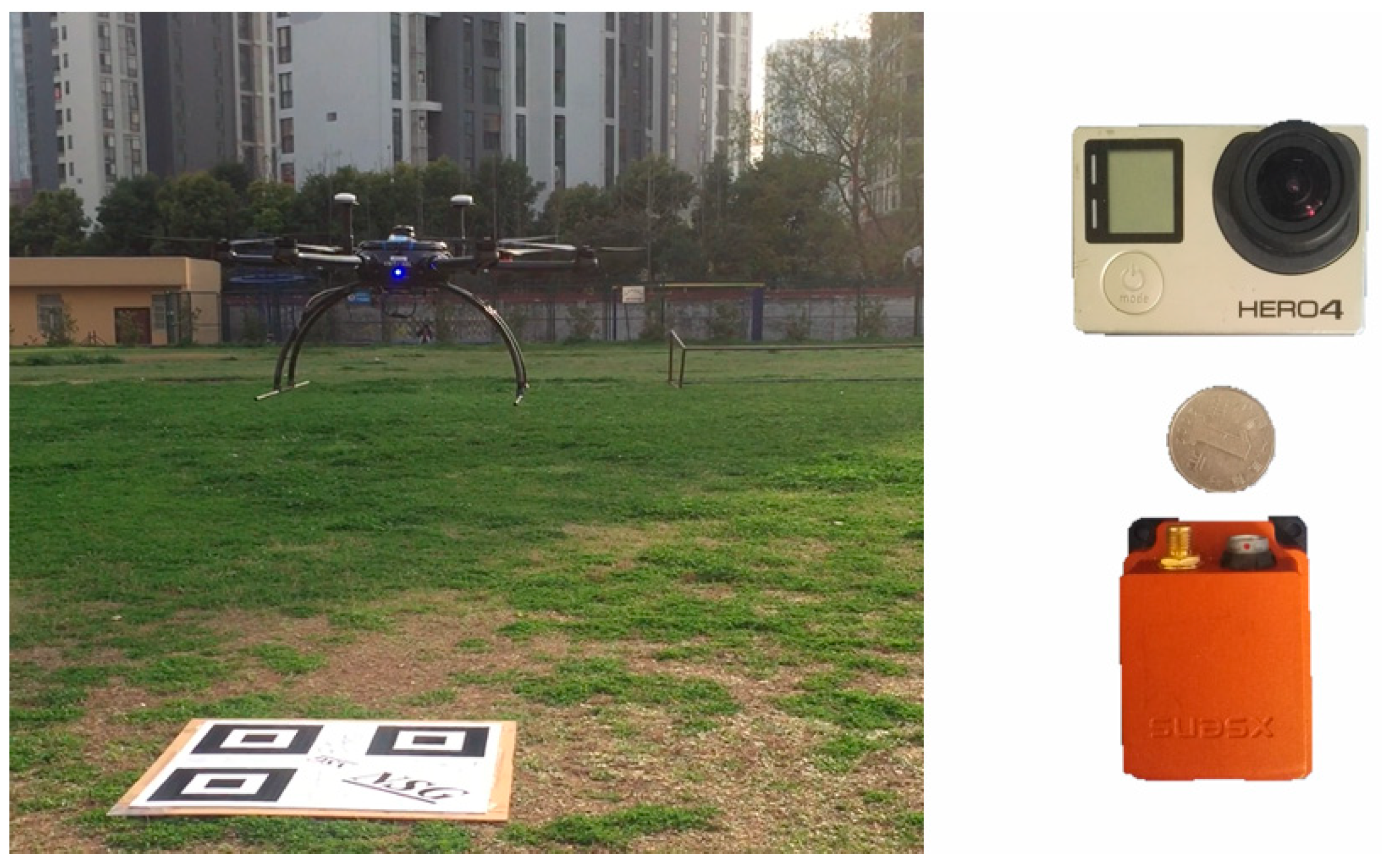
The results of our hierarchical vision-based localization field experiments are presented in this section. In these experiments, a motion camera GOPRO4 with a resolution of 1080 p is installed to look downwards relative to the UAV. The camera is assumed to be calibrated correctly in advance, and the intrinsic parameters are known. The employed UAV is a six-rotor aircraft with an arm length of 1.6 m, which is armed by a Global Positioning System (GPS) and an IMU. The UAV rotors can have a manual or autonomous flight depending on the GPS & IMU system. A XSENS product (MTi-G-700) [28] is used as the IMU module, which can output high-precision angular and accelerated velocities at 100~400 Hz and has a low latency (<2 ms). The details of the employed UAV and onboard sensors are shown in Table 1. In addition, a base station is set on the ground and Differential GPS is employed to provide a centimeter level accuracy for UAV position. Figure 5 shows the employed aircraft with onboard sensors and the landing object. All calculations are programed as nodes and the flight data is recorded from onboard sensors and considered as the ground truth for comparisons. The designed RQRLP is placed on the ground and the relative height is approximately zero m. The experiments begin when the landing object can be detected by the flying vehicle. The position and size of the three location markers in the RQRLP object are assumed to be known in advance.
5.1. RQRLP-Based Localization
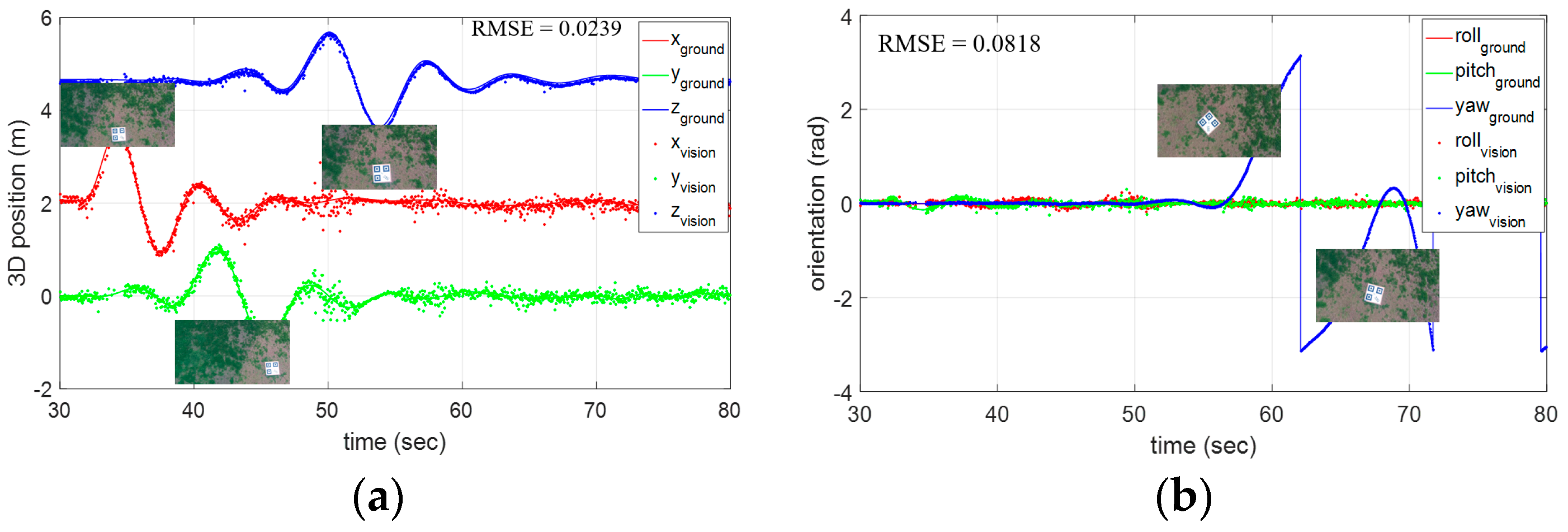
In the first experiment, the UAV is required to perform a series of typical movements, such as forward, backward, left, right, up and down, and several 360° spins. These movements involve all possibilities of a general UAV flight, and could be recovered by the onboard vision. The localization result and the ground truth from the onboard inertial sensors are shown with time in Figure 6. The corresponding errors have been also calculated: there is a small error with a RMSE (Root Mean Square Error) of 0.0239 m in the 3D position, while the RMSE in the orientation is 0.0818 rad. The results show good performance for the proposed vision-based pose recovery method with our designed RQRLP.
5.2. Hierarchical Localization for an Open Landing
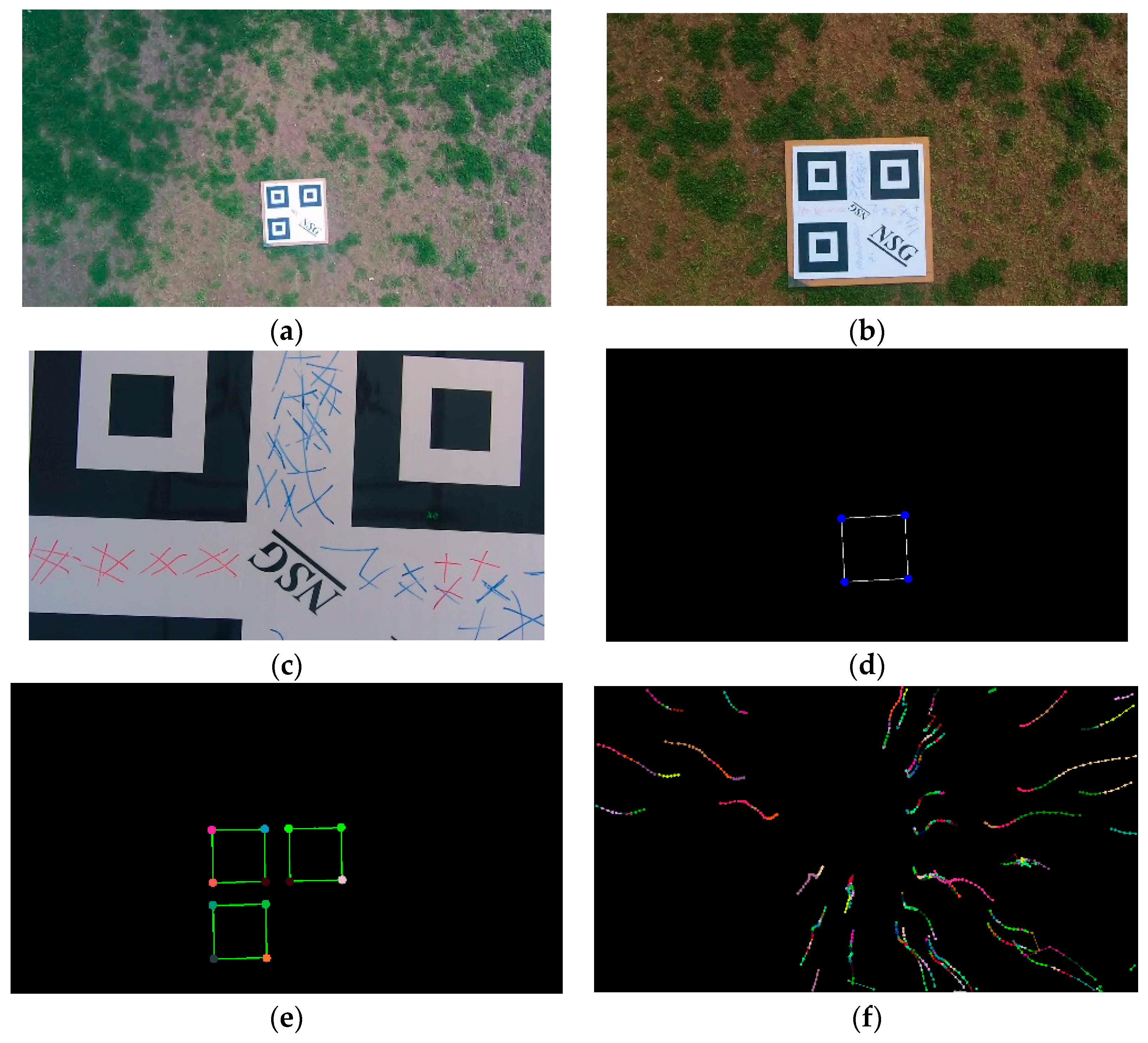
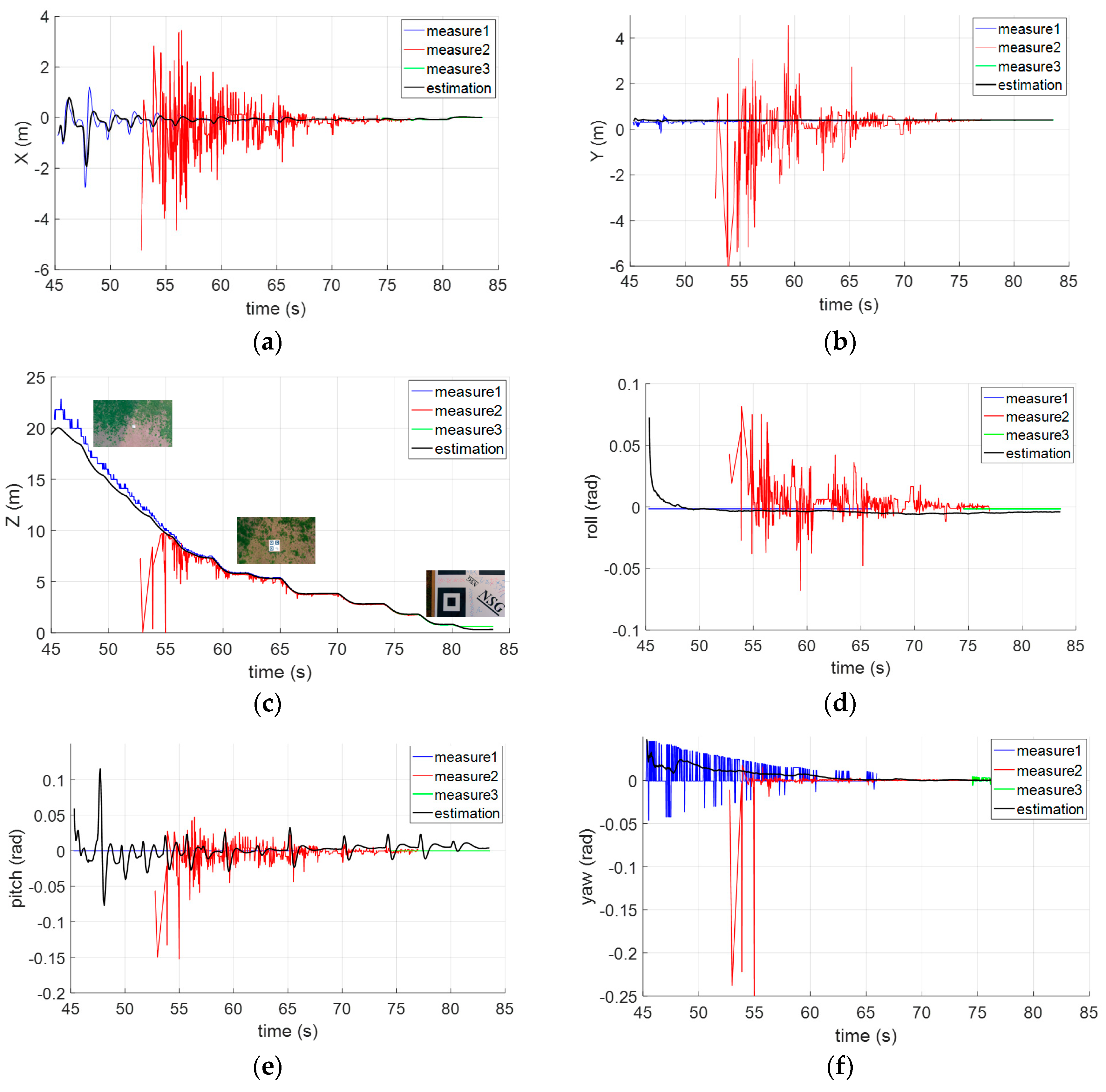
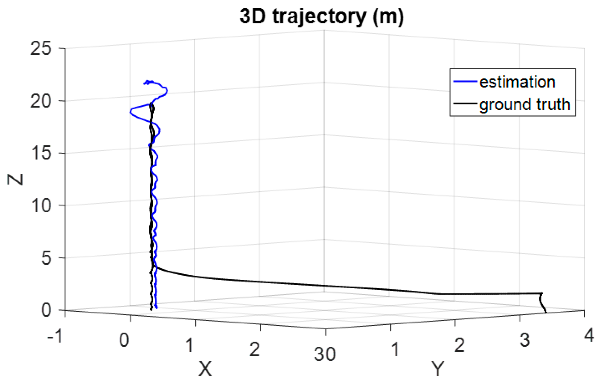
To test the presented hierarchical vision-based framework in the previous section, another flight experiment has been carried out. The employed aircraft starts to decline at a of height 20 m. At the beginning, the object RQRLP is so small in the field-of-view of the UAV that the detailed detection for the RQRLP is inaccurate and the recovered pose based on the vision “Adjustment” node has a large error. Alternatively, a rough outline of the RQRLP could be segmented from the background, and is used in the “Approaching” node to provide the relative position and orientation information, as shown in Figure 7a. As the UAV is declining below the height of 10 m, as shown in Figure 7b, the location markers in the RQRLP can be recognized and the calculated pose solution from the “Adjustment” node tends to stabilize gradually. In the end of the landing, the UAV is so close with the landing object that the RQRLP is almost out of the view of the onboard vision, as shown in Figure 7c. At this moment, the optic-flow tracker in the “Touchdown” node is able to calculate the relative pose continuously by tracking the feature points between image frames and to ensure the final landing pose. The corresponding detection process of these three vision nodes are also shown in Figure 7d–f, respectively. The localization result from the hierarchical vision framework and the independent solutions from the three vision nodes have been displayed in Figure 8. To enable a smooth visual localization, all available solutions are used as the measurements of the federated EKF framework and contribute to the final estimation. As a result, an optimal estimation could be acquired by the proposed hierarchical vision-based framework. In addition, the optimal estimation is compared with the 3D flight trajectory based on DGPS (Differential Global Positioning System) in Figure 9.
5.3. Performance Analysis and Comparison
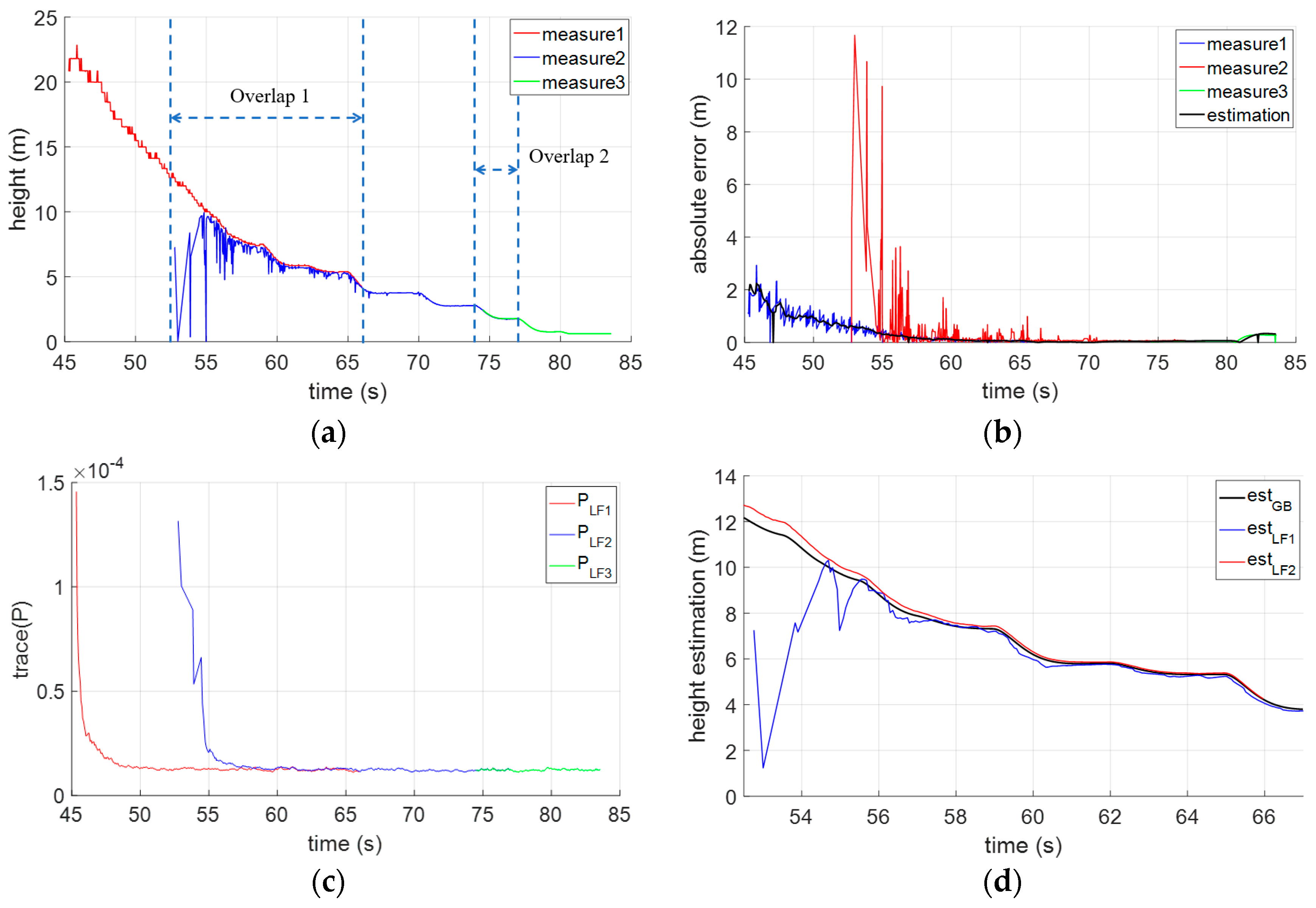
It can be noted that detection or localization precision would be affected when the object feature is almost out of view. During such a landing process, from a height of 20 m, the onboard camera kept detecting the landing object RQRLP to calculate the relative pose by using the three vision nodes in the proposed hierarchical framework. The height measurements with timestamp were acquired and have been shown in Figure 10a. It is found to be true that the localization is unstable or failed when the feature is too small to detect in the view. In other words, the detection or localization precision is dynamically changing as the detecting range. As shown in Figure 6b, the absolute errors on three measurements have been calculated and can illustrate this point. In our work, it is of great importance to fuse no less than two measurements in the overlaps in Figure 6a. For example, in the region of Overlap 1, the allocation parameter is updated according to the posterior covariance of each local filter , calculated in Figure 10c, and these can be used to trade off either measurement or local filter, whichever is be more credible. Depending on the real-time acquired , the final height estimation is available in Figure 10d. By the comparison with the ground truth, the height RMSE of local or global estimations have been calculated to be 0.065 m, 0.0835 m, and 0.037 m, respectively. It can be observed that localization is improved by such a federated fusing strategy.
In addition, the performance of the proposed hierarchical localization framework is illustrated by comparison with other typical methods. First, localization precision and range are considered as two main factors for such a comparison. As mentioned above, the RMSE is used to evaluate the localization precision. Range refers to relative distance, and these vision-based methods have been studied in the literature. Some methods could provide a 6-DOF or less pose for the UAV. Moreover, either the employed camera parameters or the landing object’s size would affect the performance of these vision methods. Image resolution and the field-of-view are considered as camera parameters. Hence, the reference information, involving the landing object size, the full- or semi-orientation, the employed camera resolution and field-of-view, have been also collected for a scientific comparison. These detailed characteristics of four vision-based methods and our method are given in Table 2. The four methods were selected since almost all the information of interest has been provided in their work. It can be seen that the smaller or narrower the range is from the onboard camera to the landing object, the better precision is ensured. While a centimeter-level precision has been obtained by the other referenced methods, our hierarchical vision localization is able to calculate the 6-DOF pose between a larger range of 0~20 m. This means that, based on such a hierarchical framework, the UAV pose guidance would be enough and practical for an open landing.
6. Conclusions
In this paper, a hierarchical vision-based localization framework has been presented for UAV landing. In the hierarchical framework, the landing was defined in three phases: “Approaching”, “Adjustment”, and “Touchdown”. For the three phases, object features at different scales are able to be extracted for UAV pose recovery. And the landing object RQRLP has also been designed for hierarchical vision detection. These original localizations are then integrated as independent measurements into a costumed federated EKF framework, which enables the final localization to be smooth and robust. Several typical experiments have been performed in the field and the results were analyzed to display the performance of our hierarchical vision localization framework. Such a hierarchical vision-based framework with a centimeter-level precision has a longer localization range and is thought to be significant for an open landing.
Author Contributions
H.Y. and C.X. conceived and designed the experiments; H.Y., W.Z. and S.X. performed the experiments; Y.W., C.Z. and F.Z. contributed the quadrotor platform and the experimental materials; H.Y. and Z.Y. analyzed the data; H.Y. and Q.L. wrote the paper.
Acknowledgments
This work reported in this paper is the product of several research stages at George Mason University and Wuhan University of Technology and has been sponsored in part by the Natural Science Foundations of China (51579204 and 51679180), Double First-rate Project of WUT (472-20163042). Qiliang Li would like to acknowledge the support of the Virginia Microelectronics Consortium (VMEC) research grant.
Conflicts of Interest
The authors declare no conflict of interest.
References
- Kendoul, F. A survey of advances in guidance, navigation and control of unmanned rotorcraft systems. J. Field Robot. 2012, 29, 315–378. [Google Scholar] [CrossRef]
- Saripalli, S.; Montgomery, J.F.; Sukhatme, G.S. Visually Guided Landing of an Unmanned Aerial Vehicle. IEEE Trans. Robot Auton. 2003, 19, 371–380. [Google Scholar] [CrossRef]
- Lange, S.; Sunderhauf, N.; Protzel, P. A Vision Based Onboard Approach for Landing and Position Control of an Autonomous Multirotor UAV in GPS-Denied Environments. In Proceedings of the International Conference on Advanced Robotics (ICAR), Munich, Germany, 22–26 June 2009; pp. 22–26. [Google Scholar]
- Xu, G.; Zeng, X.; Tian, Q.; Guo, Y.; Wang, R.; Wang, B. Use of Land’s Cooperative Object to Estimate UAV’s Pose for Autonomous Landing. Chin. J. Aeronaut. 2013, 26, 1498–1505. [Google Scholar] [CrossRef]
- Yang, S.; Scherer, S.A.; Schauwecker, K.; Zell, A. Autonomous Landing of MAVs on an Arbitrarily Textured Landing Site Using Onboard Monocular Vision. J. Intell. Robot. Syst. 2014, 74, 27–43. [Google Scholar] [CrossRef]
- Mondragon, I.F.; Campoy, P.; Martinez, C.; Olivares-Méndez, M.A. 3D pose estimation based on planar object tracking for UAVs control. In Proceedings of the 2010 IEEE International Conference on Robotics and Automation, Anchorage, AK, USA, 3–7 May 2010; pp. 35–41. [Google Scholar]
- Martinez, C.; Mondragon, I.F.; Olivares-Mendez, M.A.; Campoy, P. On-board and Ground Visual Pose Estimation Techniques for UAV Control. J. Intell. Robot. Syst. 2011, 61, 301–320. [Google Scholar] [CrossRef] [Green Version]
- Brockers, R.; Bouffard, P.; Ma, J.; Matthies, L.; Tomlin, C. Autonomous landing and ingress of micro-air-vehicles in urban environments based on monocular vision. In Proceedings of the Micro- and Nanotechnology Sensors, Systems, and Applications III, Orlando, FL, USA, 25–29 April 2011; p. 803111. [Google Scholar]
- Sanchez-Lopez, J.L.; Pestana, J.; Saripalli, S.; Campoy, P. An Approach Toward Visual Autonomous Ship Board Landing of a VTOL UAV. J. Intell. Robot. Syst. 2014, 74, 113–127. [Google Scholar] [CrossRef]
- Lin, S.; Garratt, M.A.; Lambert, A.J. Monocular vision-based real-time target recognition and tracking for autonomously landing an UAV in a cluttered shipboard environment. Auton. Robots 2016, 41, 881–901. [Google Scholar] [CrossRef]
- Li, A.Q.; Coskun, A.; Doherty, S.M.; Ghasemlou, S.; Jagtap, A.S.; Modasshir, M.; Rahman, S.; Singh, A.; Xanthidis, M.; O’Kane, J.M.; et al. Experimental Comparison of open source Vision based State Estimation Algorithms. Int. Symp. Exp. Robot. 2016, 775–786. [Google Scholar] [CrossRef]
- Srinivasan, M.V. Honeybees as a model for the study of visually guided flight navigation and biologically inspired robotics. Physiol. Rev. 2011, 91, 413–460. [Google Scholar] [CrossRef] [PubMed]
- Chahl, J.S.; Srinivasan, M.V.; Zhang, S.W. Landing strategies in honey bees and applications to uninhabited airborne vehicles. Int. J. Robot. Res. 2004, 23, 101–110. [Google Scholar] [CrossRef]
- Strydom, R.; Thurrowgood, S.; Srinivasan, M.V. Visual Odometry: Autonomous UAV Navigation using Optic Flow and Stereo. In Proceedings of the Australasian Conference on Robotics and Automation, Melbourne, Australia, 2–4 December 2014. [Google Scholar]
- Shen, S.; Mulgaonkar, Y.; Michael, N.; Kumar, V. Vision-based state estimation for autonomous rotorcraft mavs in complex environments. In Proceedings of the 2013 IEEE International Conference on Robotics and Automation, Karlsruhe, Germany, 6–10 May 2013; pp. 1758–1764. [Google Scholar]
- Forster, C.; Pizzoli, M.; Scaramuzza, D. SVO: Fast semi-direct monocular visual odometry. In Proceedings of the 2014 IEEE International Conference on Robotics and Automation (ICRA), Hong Kong, China, 31 May–7 June 2014; pp. 15–22. [Google Scholar]
- Thurrowgood, S.; Moore, R.J.D.; Soccol, D.; Knight, M.; Srinivasan, M.V. A Biologically Inspired, Vision-based Guidance System for Automatic Landing of a Fixed-wing Aircraft. J. Field Robot. 2014, 31, 699–727. [Google Scholar] [CrossRef]
- Denuelle, A.; Thurrowgood, S.; Strydom, R.; Kendoul, F.; Srinivasan, M.V. Biologically-inspired visual stabilization of a rotorcraft UAV in unknown outdoor environments. In Proceedings of the 2015 International Conference on Unmanned Aircraft Systems (ICUAS), Denver, CO, USA, 9–12 June 2015; pp. 1084–1093. [Google Scholar]
- Kendoul, F.; Fantoni, I.; Nonami, K. Optic flow-based vision system for autonomous 3D localization and control of small aerial vehicles. Robot. Auton. Syst. 2009, 57, 591–602. [Google Scholar] [CrossRef]
- Herisse, B.; Hamel, T.; Mahony, R.; Russotto, F.X. Landing a VTOL Unmanned Aerial Vehicle on a Moving Platform Using Optical Flow. IEEE Trans. Robot. 2012, 28, 77–89. [Google Scholar] [CrossRef]
- Wenzel, K.E.; Rosset, P.; Zell, A. Low-Cost Visual Tracking of a Landing Place and Hovering Flight Control with a Microcontroller. J. Intell. Robot. Syst. 2010, 57, 297–311. [Google Scholar] [CrossRef]
- Li, P.; Garratt, M.; Lambert, A. Monocular Snapshot-based Sensing and Control of Hover Takeoff and Landing for a Low-cost Quadrotor: Monocular Snapshot-based Sensing and Control. J. Field Robot. 2015, 32, 984–1003. [Google Scholar] [CrossRef]
- Kong, W.; Hu, T.; Zhang, D.; Shen, L.; Zhang, J. Localization Framework for Real-Time UAV Autonomous Landing: An On-Ground Deployed Visual Approach. Sensor 2017, 17, 1437. [Google Scholar] [CrossRef] [PubMed]
- Ma, Z.; Hu, T.; Shen, L. Stereo vision guiding for the autonomous landing of fixed-wing UAVs: A saliency-inspired approach. Int. J. Adv. Robot. Syst. 2016, 13, 43. [Google Scholar] [CrossRef]
- Yuan, H.; Xiao, C.; Xiu, S.; Wen, Y.; Zhou, C.; Li, Q. A new combined vision technique for micro aerial vehicle pose estimation. Robotics 2017, 6, 6. [Google Scholar] [CrossRef]
- Zhang, Z. A flexible new technique for camera calibration. IEEE Trans. Pattern Anal. Mach. Intell. 2000, 22, 1330–1334. [Google Scholar] [CrossRef]
- Bazargani, H.; Bilaniuk, O.; Laganière, R. A fast and robust homography scheme for real-time planar target detection. J. Real-Time Image Proc. 2015, 1–20. [Google Scholar] [CrossRef]
- XSENS MTi-G-700. Available online: https://www.xsens.com/products/mti-g-700/ (accessed on 30 March 2018).
- Breitenmoser, A.; Kneip, L.; Siegwart, R. A Monocular Vision based System for 6D Relative Robot Localization. In Proceedings of the IEEE/RSJ International Conference on Intelligent Robots and Systems (IROS), San Francisco, CA, USA, 25–30 September 2011. [Google Scholar]
- Sharp, C.S.; Shakernia, O.; Sastry, S.S. A vision system for landing an unmanned aerial vehicle. In Proceedings of the IEEE International Conference on Robotics and Automation (Cat. No.01CH37164), Seoul, Korea, 21–26 May 2001; pp. 1720–1727. [Google Scholar]
Figure 1.
The landing object: Robust and Quick Response Landing Pattern (RQRLP).

Figure 2.
Vision based 3D coordinate systems and the object-to-image homography.

Figure 3.
The hierarchical vision-based localization framework.

Figure 4.
The customized federated filter for the hierarchical vision-based localization.

Figure 5.
Left: Landing object RQRLP and the employed six-rotors aircraft system. Right: Onboard camera and the Inertial Measurement Unit (IMU) module.
Figure 5.
Left: Landing object RQRLP and the employed six-rotors aircraft system. Right: Onboard camera and the Inertial Measurement Unit (IMU) module.

Figure 6.
Vision-based pose recovery by the RQRLP landing object. (a) 3D position with respect to the RQRLP, in meters (m); (b) Orientation angles involving the roll, pitch and yaw, in radians (rad).
Figure 6.
Vision-based pose recovery by the RQRLP landing object. (a) 3D position with respect to the RQRLP, in meters (m); (b) Orientation angles involving the roll, pitch and yaw, in radians (rad).

Figure 7.
Feature extraction in different landing phases by the hierarchical vision-based framework. (a–c) Real images captured in the “Approaching”, “Adjustment”, and “Touchdown” phases, respectively; (d–f) the corresponding extracted features.
Figure 7.
Feature extraction in different landing phases by the hierarchical vision-based framework. (a–c) Real images captured in the “Approaching”, “Adjustment”, and “Touchdown” phases, respectively; (d–f) the corresponding extracted features.

Figure 8.
The hierarchical vision-based localizations and estimation for an open landing. (a–c) 3D position with respect to the RQRLP in meters (m); (d–f) orientation angles involving the roll, pitch, and yaw in radians (rad).
Figure 8.
The hierarchical vision-based localizations and estimation for an open landing. (a–c) 3D position with respect to the RQRLP in meters (m); (d–f) orientation angles involving the roll, pitch, and yaw in radians (rad).

Figure 9.
3D trajectory estimation using the hierarchical vision framework and ground truth (DGPS).

Figure 10.
The landing height estimation by the hierarchical vision localization framework. (a) The height measurements by three vision nodes “Approach”, “Adjustment” and “Touchdown”; (b) The absolute errors of visual measurements and estimation; (c) Traces of the covariance (P) of the three local filters (LF1~3); (d) height estimations from LF1, LF2 and GloBal update (GB).


Table 1.
Specification of the devices in the experiment.
| Device | Specification |
|---|---|
| UAV frame | six rotors, arm length 1.6 m, total weight 3.2 kg |
| GOPRO camera | 1080 p, 50 fps, focal length 1280 pixels, principal point: (948.9, 543.2), distortion factor (−0.00908, −0.03128, 0.00109, −0.00198, 0) |
| Xsens IMU | 100~400 Hz, Gyroscope: full range 450 deg/s, noise density 0.01 ; Acceleration: full range 50 m/s2, noise density 80 . |
Table 2.
Comparisons between other methods from References (Ref) and our method.
| Methods | Ref [6] | Ref [29] | Ref [5] | Ref [30] | Ours |
|---|---|---|---|---|---|
| Position RMSE (m) | 0.2467 | 0.015 | 0.0392 | <0.05 | 0.0639 |
| Orientation RMSE () | 0.0653 | 0.0209 | 0.0436 | <0.0872 | 0.0818 |
| Range (m) | 3~10 | 0.677~1.741 | 1 | 1~1.1 | 0~20 |
| Pose (DOF) | 4-DOF | 6-DOF | 6-DOF | 6-DOF | 6-DOF |
| Object size (m) | 0.91 × 1.19 | 0.01 (diameter) | 0.18 (diameter) | unknown | 0.85 × 0.85 |
| Vision Resolution (pixels) | 640 × 480 | 752 × 480 | 640 × 480 | 320 × 240 | 1920 × 1080 |
| field of view () | unknown | 90 | 90 | unknown | 90 |
© 2018 by the authors. Licensee MDPI, Basel, Switzerland. This article is an open access article distributed under the terms and conditions of the Creative Commons Attribution (CC BY) license (http://creativecommons.org/licenses/by/4.0/).
Share and Cite
MDPI and ACS Style
Yuan, H.; Xiao, C.; Xiu, S.; Zhan, W.; Ye, Z.; Zhang, F.; Zhou, C.; Wen, Y.; Li, Q. A Hierarchical Vision-Based UAV Localization for an Open Landing. Electronics 2018, 7, 68. https://doi.org/10.3390/electronics7050068
AMA Style
Yuan H, Xiao C, Xiu S, Zhan W, Ye Z, Zhang F, Zhou C, Wen Y, Li Q. A Hierarchical Vision-Based UAV Localization for an Open Landing. Electronics. 2018; 7(5):68. https://doi.org/10.3390/electronics7050068
Chicago/Turabian StyleYuan, Haiwen, Changshi Xiao, Supu Xiu, Wenqiang Zhan, Zhenyi Ye, Fan Zhang, Chunhui Zhou, Yuanqiao Wen, and Qiliang Li. 2018. "A Hierarchical Vision-Based UAV Localization for an Open Landing" Electronics 7, no. 5: 68. https://doi.org/10.3390/electronics7050068
Note that from the first issue of 2016, this journal uses article numbers instead of page numbers. See further details here.