Next Article in Journal
The Electrical Properties of Plasma-Deposited Thin Films Derived from Pelargonium graveolens
Previous Article in Journal
Data-Driven ECG Denoising Techniques for Characterising Bipolar Lead Sets along the Left Arm in Wearable Long-Term Heart Rhythm Monitoring
 
 
Correction published on 9 April 2019, see Electronics 2019, 8(4), 415.
Review

Frequency and Polarization-Diversified Linear Sampling Methods for Microwave Tomography and Remote Sensing Using Electromagnetic Metamaterials

by
Mehdi Salarkaleji
1,*,
Mohammadreza Eskandari
2,
Jimmy Ching-Ming Chen
3 and
Chung-Tse Michael Wu
4
1
Department of Electrical and Computer Engineering, Wayne State University, Detroit, MI 48202, USA
2
Electrical Engineering, University of Shahreza, Shahreza 86149-56841, Iran
3
Division of Engineering Technology, Wayne State University, Detroit, MI 48202, USA
4
Department of Electrical and Computer Engineering, Rutgers University, Piscataway, NJ 08854, USA
*
Author to whom correspondence should be addressed.
Electronics 2017, 6(4), 85; https://doi.org/10.3390/electronics6040085
Submission received: 13 September 2017 / Revised: 9 October 2017 / Accepted: 16 October 2017 / Published: 18 October 2017

Abstract

:
Metamaterial leaky wave antennas (MTM-LWAs), one kind of frequency scanning antennas, exhibit frequency-space mapping characteristics that can be utilized to obtain a sufficient field of view (FOV) and reconstruct shapes in both remote sensing and microwave imaging. In this article, we utilize MTM-LWAs to conduct a spectrally encoded three-dimensional (3D) microwave tomography and remote sensing that can reconstruct conductive targets with various dimensions. In this novel imaging technique, we employ the linear sampling method (LSM) as a powerful and fast reconstruction approach. Unlike the traditional LSM using only one single frequency to illuminate a fixed direction, the proposed method utilizes a frequency scanning MTM antenna array able to accomplish frequency-space mapping over the targeted 3D background that includes unknown objects. In addition, a novel technique based on a frequency and polarization hybrid method is proposed to improve the shape reconstruction resolution and stability in ill-posed inverse problems. Both simulation and experimental results demonstrate the unique advantages of the proposed LSM using MTM-LWAs with frequency and polarization diversity as an efficient 3D remote sensing and tomography scheme.

1. Introduction

Imaging and identifying targets based on electromagnetic radiation have a long history, e.g., X-ray imaging traces back to the early twentieth century. On the other hand, microwaves have more penetration depth and a less destructive impact on targets than higher frequency waves like X-ray, so the great tendency exists towards microwave imaging [1,2]. In general, imaging methods based on so-called quantitative solutions to an inverse scattering problem are usually categorized into two classes, i.e., weak scattering approximation and nonlinear optimization. The former exploits low or high frequency approximations of the scattering phenomenon to linearize the data-to-unknown relationship, and it is typically capable of providing only a rough description of the target’s morphology [3,4,5]. Ill-posedness and non-linearity of inverse scattering problems are the two main complications in the solving process. As such, different methods were proposed to approximate the scattering based on certain constrains on the scatterer. For example, Born approximation is used when the scatterer has small permittivity and a small size compared to the wavelength. On the other hand, nonlinear optimization deals with inverse scattering problems in its full nonlinearity to regulate both morphology and electromagnetic contrasts of the target. In the case of using optimization approaches based on minimizing an error function, the process starts with an initial guess and is optimized during iteration stages. Since in each stage the scattering problem must be solved, nonlinear optimization is slower, but has greater accuracy and quality of imaging than weak scattering approximation [6,7]. Other examples of these two quantitative methods are the modified gradient method [3], the distorted Born approximation [8,9], the contrast source method [10], the subspace optimization method [11], and the least square optimization method [12,13].
Other than quantitative approaches, there exist qualitative methods aiming to find only shapes and locations of targets. The linear sampling method (LSM) is one of the well-developed qualitative methods in inverse scattering, which was first introduced in 1996 for scalars [14], and later on for vectors [15]. LSM is a very rapid computational method when compared with other optimization approaches, as it requires very few priori data and involves only the solutions of linear ill-posed problems. Detecting unknown objects using LSM has found diverse applications in many areas, such as target identification, ground penetrating radars (GPR), medical diagnostics for cancer, and hypothermia [16,17].
The complexity of three-dimensional (3D) imaging has always been an inevitable issue when it comes from theoretical analysis to physical implementation [18]. Taking advantage of LSM in reconstructing both two-dimensional (2D) and 3D images from scattered field data, we present a recently developed novel type spectrally-encoded LSM method using metamaterial leaky wave antennas (MTM-LWAs) to decrease the intricacy of the system and computation costs. In recent years, several MTM platforms have demonstrated exotic electromagnetic (EM) properties [19,20,21,22,23,24,25,26,27,28]. In particular, it is well known that MTM-LWAs exhibit backfire-to-endfire frequency scanning characteristics, and thus can be utilized to cover a wide field of view (FOV) for detecting unknown targets over the operating frequency band [29,30,31]. As distinct positions of the unknown targets are encoded with a specific spectral component, microwave tomography as well as remote sensing for the entire 3D scenario can be carried out immediately by processing spectrally encoded reflected waves using LSM, thereby increasing the FOV and system sensing speed.
In addition, in order to improve the image quality obtained from LSM, recently, the hybridization combining LSM and quantitative methods was proposed to solve inverse scattering problems [32,33,34,35]. Here, we present a multi-frequency hybrid technique to reconstruct unknown object images with enhanced resolution. Although some approaches related to multi-frequency LSM have been studied [36,37], the hybrid method presented in this paper will provide a more feasible and efficient way to reconstruct targets with complex geometries than the previous works. On top of this, polarization diversity is introduced into the hybrid method to improve the reconstruction stability with respect to variances of regularization parameters. In general, it is a non-trivial task to choose regularization parameters in order to transform an ill-posed problem into a well-posed one. With the proposed polarization hybrid method, the regularization parameters have much looser constraints in a broad range. Additionally, distorted effects caused by noises on the reconstruction are mitigated significantly by employing the multi-frequency technique, which is another advantage of the proposed technique. The paper is structured as follows. Section 2 describes the forward and inverse scattering problem of the MTM based 3D microwave tomography mechanism. The description and the experiment of microwave tomography are given in Section 3. In Section 4, employing LSM using frequency scanning MTM-LWAs for remote sensing is presented. Then, a hybrid method to improve the quality of image reconstruction by presenting a modified far-field equation to collect more scattering information for the inverse algorithms is represented in Section 5. Finally, Section 6 contains the conclusions.

2. Forward and Inverse Scattering Problem

In this section, the mechanism of the proposed MTM based 3D microwave tomography is presented. The experiment setup is shown in Figure 1. The target is composed of multi-layered perfect electric conductor (PEC) cylinders with different radiuses, where r 1 = 0.8 λ , r 2 = 1 λ and r 3 = 2 λ , and λ is the free space wavelength at 1 GHz. Two scenarios of scattering phenomena underlying MTM-LWAs processing are considered:
  • The forward scattering is based on the analytical method including mathematical formulation and identifies the required data for the inverse scattering.
  • The inverse scattering is based on LSM and represents the procedure of using the forward scattering data.
The procedure of imaging is illustrated in Figure 1, where different elevations of the target are spectrally encoded with a particular radiation beam from the MTM-LWA array. This results from the fact that MTM-LWAs exhibit frequency-dependent beam-scanning capability, and the main beam direction is a function of the frequency [38]:
θ M B ( ω ) = 90 ° sin 1 [ β ( ω ) k 0 ]
where β is the propagation constant of the LWA, and k 0 is the free space wave number. As β of MTM-LWAs is able to vary from − k 0 to + k 0 . The main beam can therefore scan continuously from θ = +180 to 0 degree, as referred to Figure 1. In what follows, we introduce the scattering fields caused by these conducting cylinders under transvers-magnetic (TM) polarization, and then discuss the formulation of LSM.

2.1. Forward Scattering Problem Based on Modal Method

Let us assume that a TM plane wave is incident upon a multi-layered PEC cylinder with different radius, as shown in Figure 1. In this setup, the scattered electrical fields for ρ and z components can be written as [39]:
E ρ s = E 0 j cos θ i e + j β cos θ i n = n = j n a n H n ( 2 ) ( β ρ sin θ i ) e j n ϕ
E z s = E 0 j sin θ i e + j β cos θ i n = n = j n a n H n ( 2 ) ( β ρ sin θ i ) e j n ϕ
where ρ , ϕ   and   z are the cylindrical coordinate components. The θ component of electrical field can then be obtained as:
E θ s = cos θ . E ρ s sin θ . E z s
where a n = J n ( β a sin θ i ) H n ( 2 ) ( β a sin θ i ) , J n and H n ( 2 ) are Bessel function and Hankel function of the second kind, respectively. In addition, E 0 is the amplitude of the incident electric field, and θ i is the incidence angle from the antenna to the target.

2.2. Inverse Scattering Problem Based on LSM

The LSM can be determined from the far field Fredholm Equation [40], as shown below:
E m ( ϕ m , ϕ i ) g ( ϕ i , p ) d ϕ i = Φ ( ϕ i , p )
where E m ( ϕ m , ϕ i ) is the far-field pattern that is scattered from the targets and is measured at angle ϕ m , whereas ϕ i is the angle of the incident plane wave. Also, g ( ϕ i , p ) is our desired solution at each pixel p in the sampling domain. Φ ( ϕ i , p ) shows the far-field pattern for a current filament along the z axis. In order to perform the LSM, Tikhonov regularization is employed at each pixel of the domain. Equation (5) shows a linear system of the formulation to be investigated, and the goal is to solve for | | g | | at all pixels p in the background, in which | | . | | is the norm operator. The solution to | | g | | can be expressed as:
| | g | | = ( n = 1 ψ n 2 ( f , μ n ) ( α + ψ n 2 ) 2 ) 1 2
where f is the Green’s function of a current line source with TM polarization, { μ n , ψ n , φ n } is the singular value decomposition (SVD) system of the far-field operator, ( f , μ n ) represents the inner product of f and μ n in Hilbert space, and α is the regularization parameter [13].

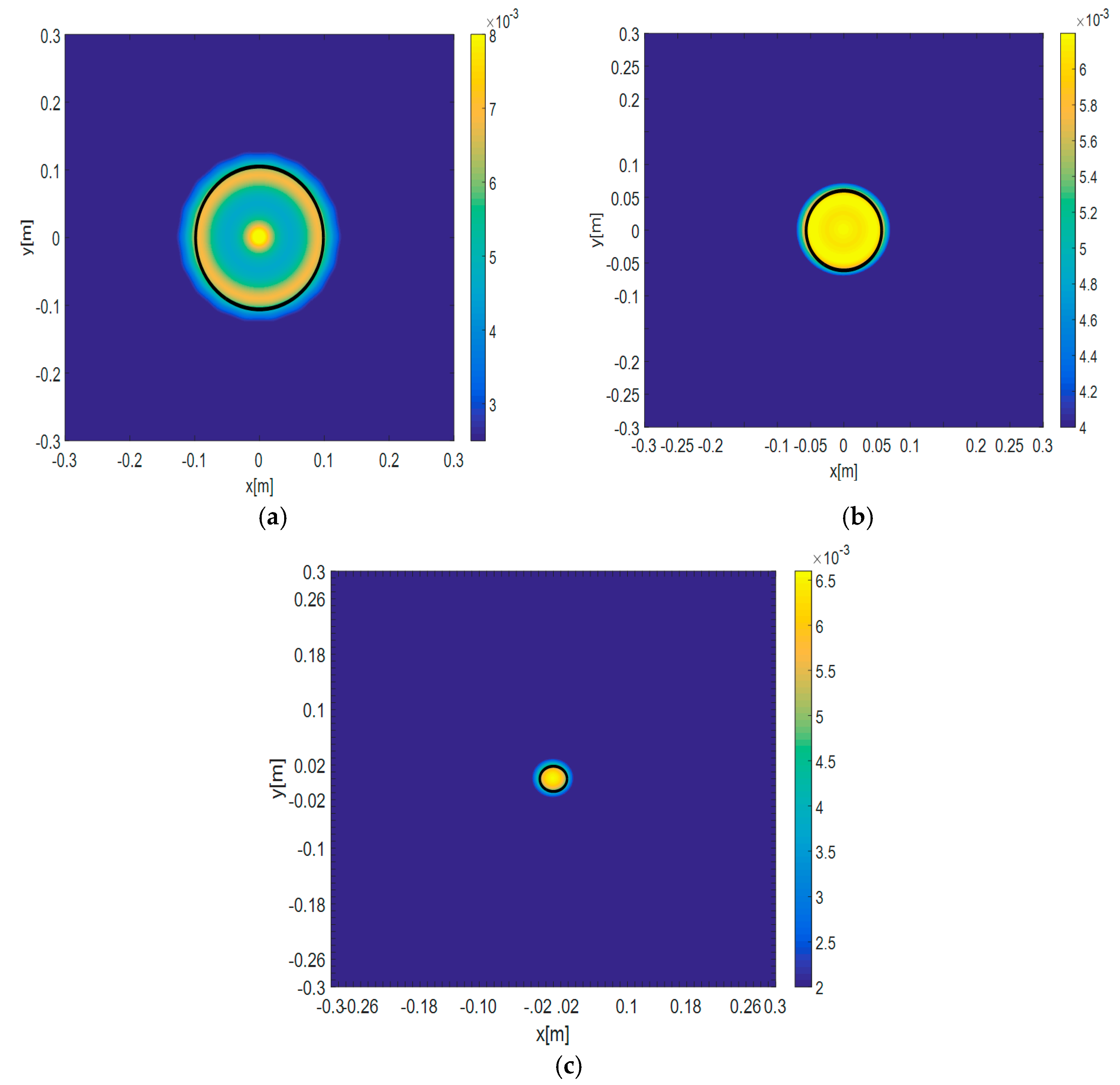
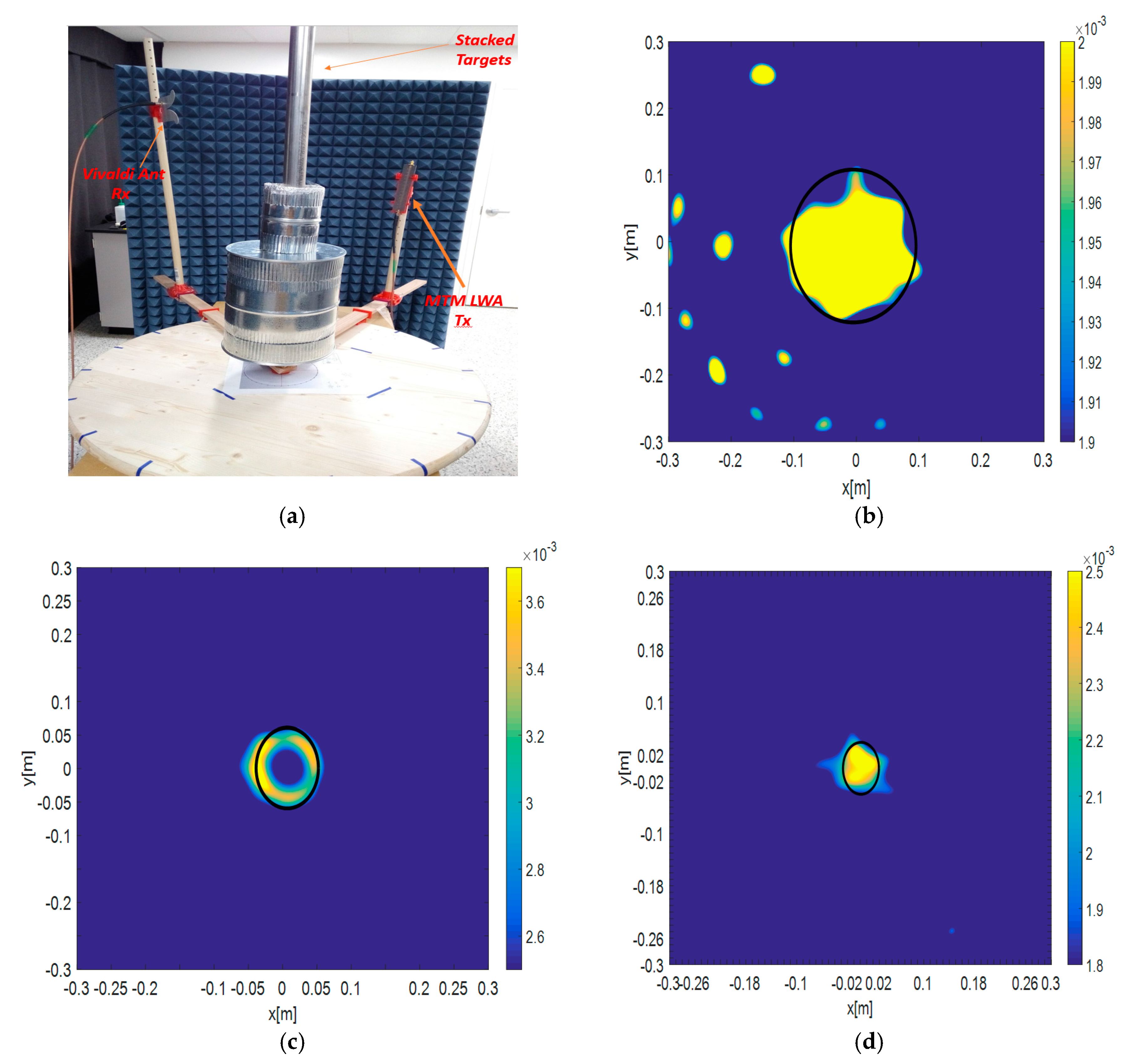
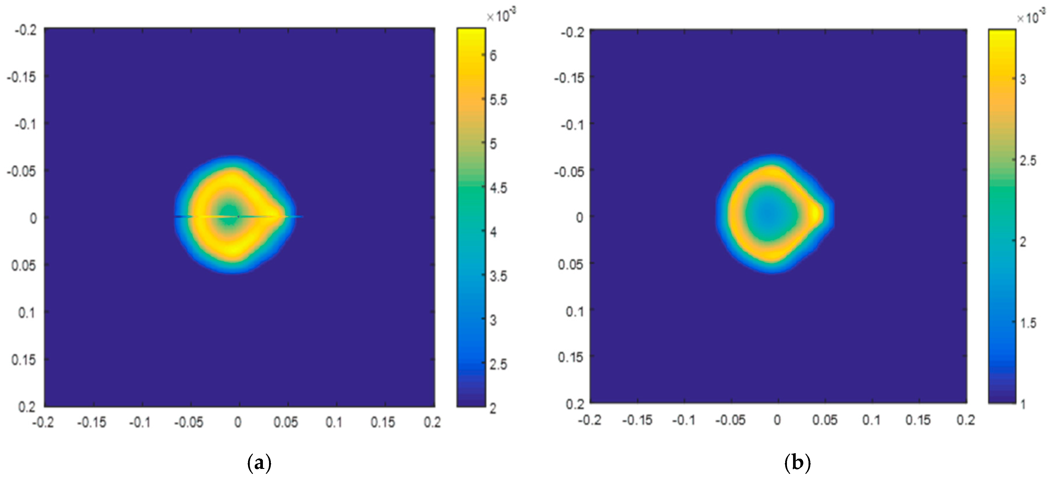
3. Microwave Tomography
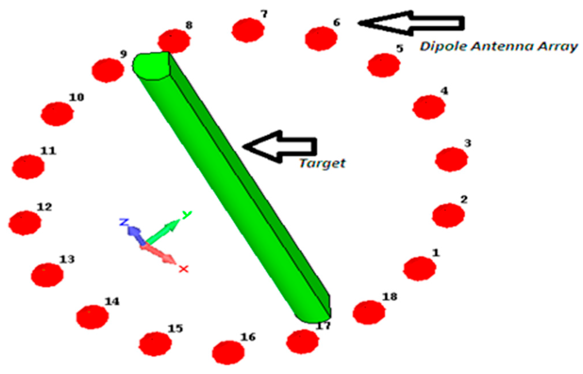
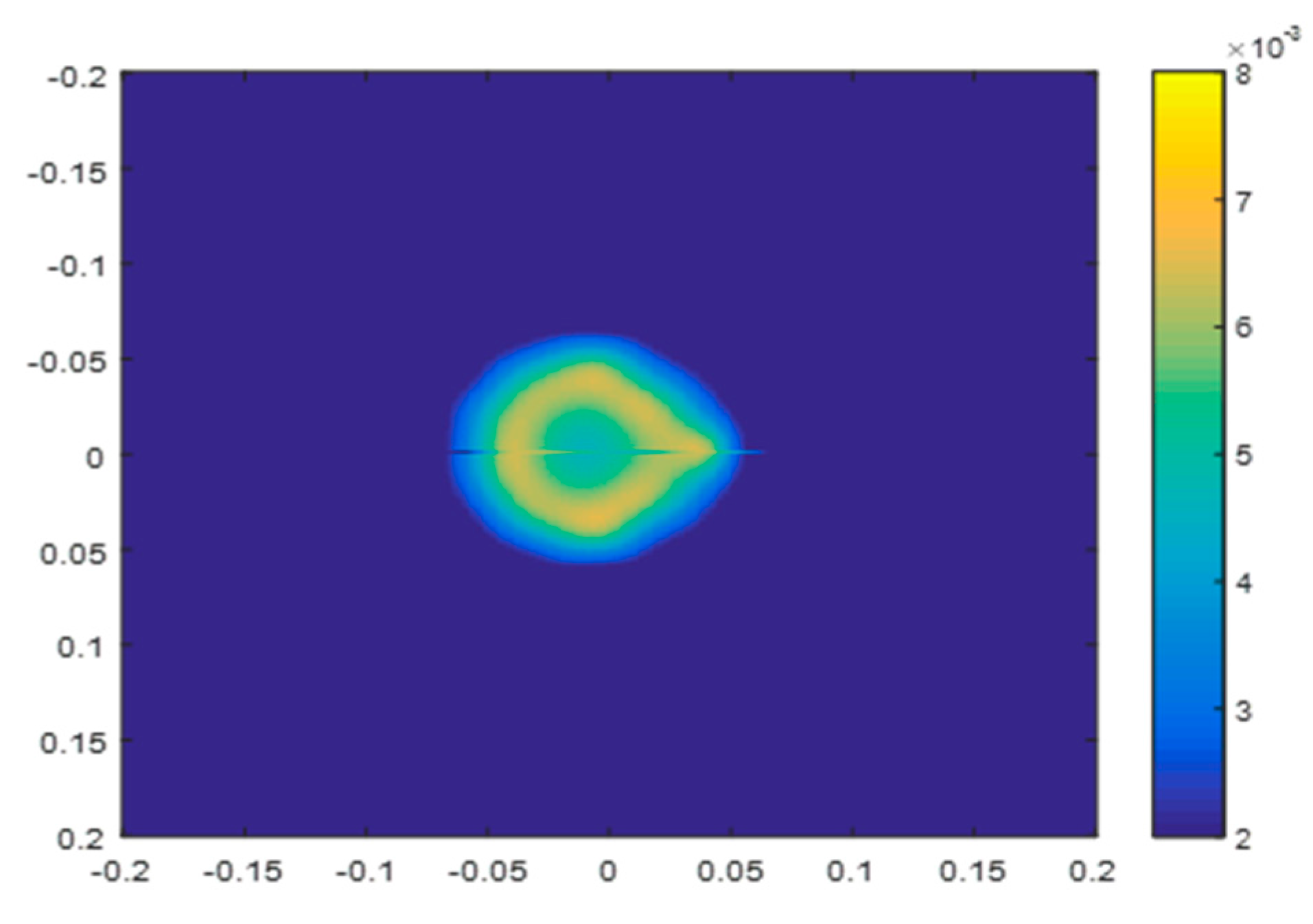
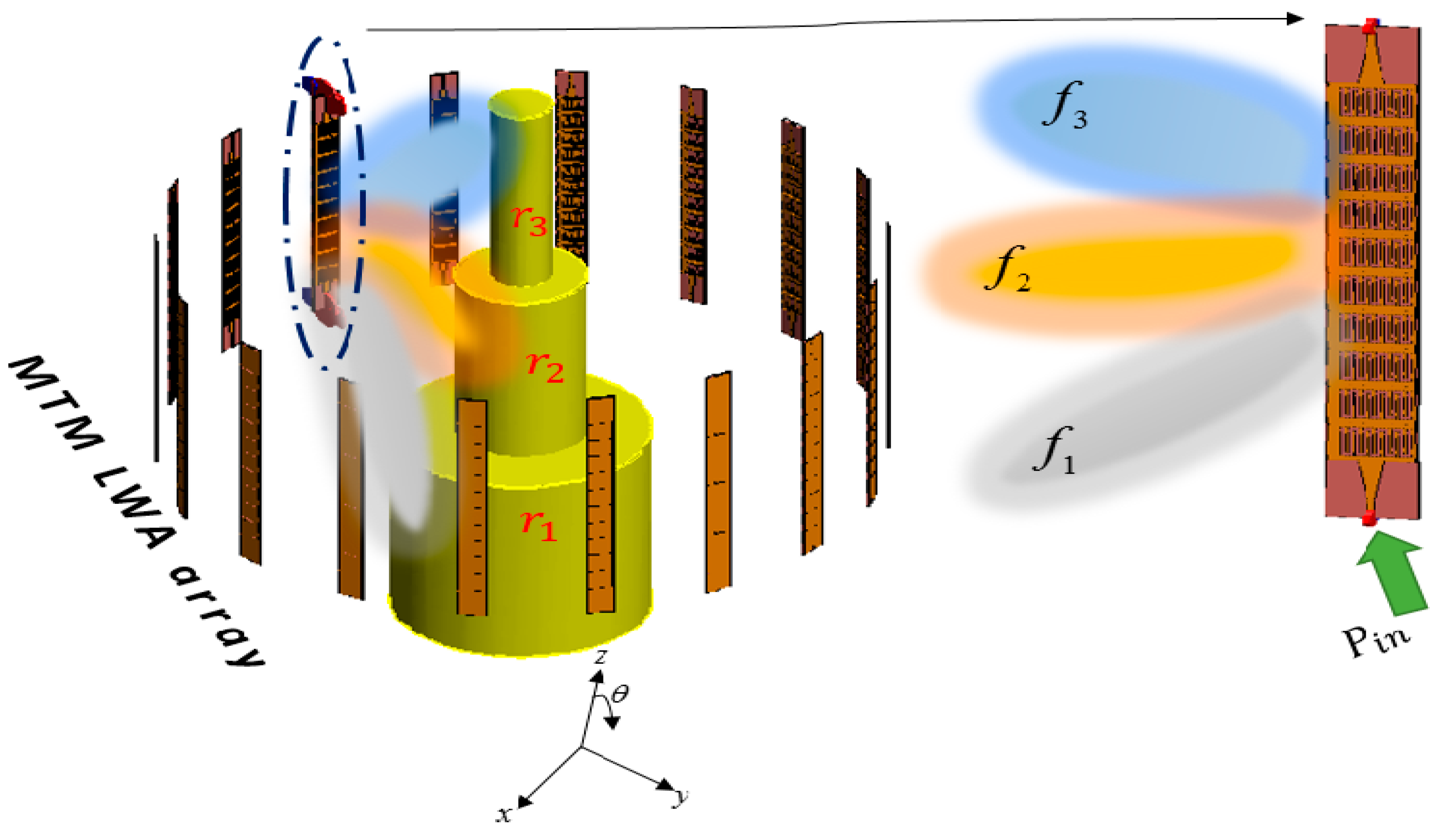
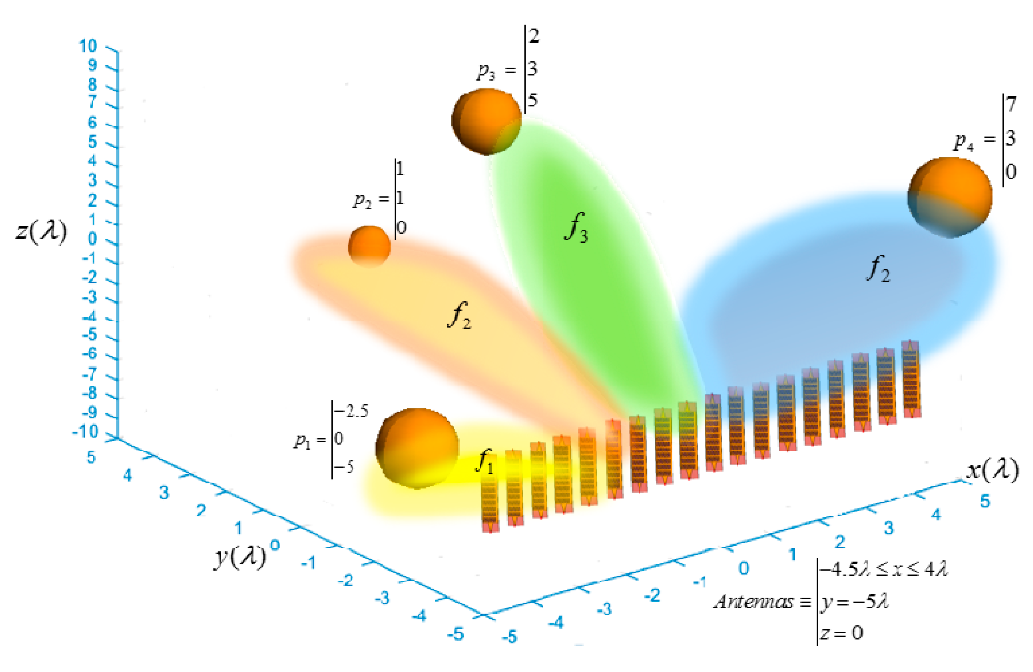
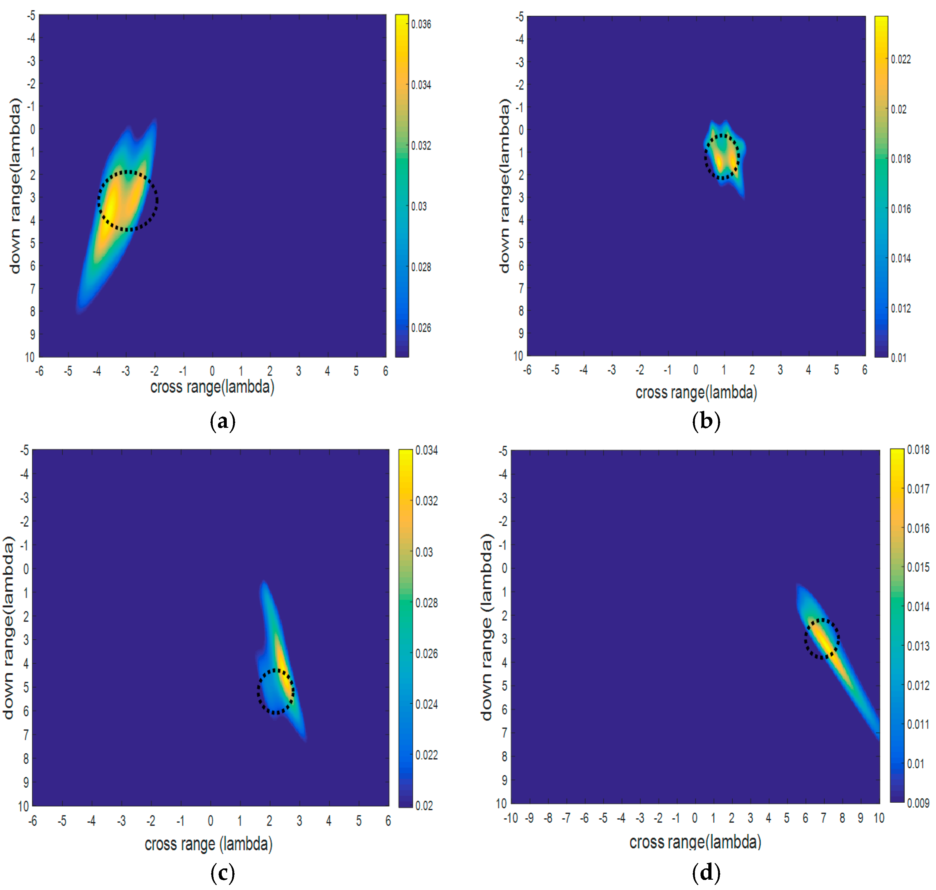
As proof-of-concept, the operating frequencies for MTM-LWAs to reconstruct the object are chosen to be 1.8, 2.4, and 3 GHz, which correspond to the backward (θ = 135°), broadside (θ = 90°), and forward radiation (θ = 45°) of the MTM-LWAs, respectively, as referred to in Figure 1. Utilizing the scattered electric fields obtained from the theoretical analysis [19], Figure 2 plots the reconstructed images using these three frequencies that map to the three distinct angular locations. In so doing, the scattered electric fields at different frequencies carry specific spatial information of the unknown target. The spectrally encoded information is then processed with the LSM algorithm to reconstruct the 2D cut of the unknown target in the full 3D space.
The measurement setup is shown in Figure 3a, in which the target is surrounded by microwave absorbers to reduce the undesired scattering. As shown in Figure 3a, an MTM-LWA serves as the interrogating spectral transmitter and a broadband Vivaldi antenna (1.5–6 GHz) is utilized as the receiver. The stacked targets composed of three conductive cylinders with different radius are located at the turn-table center. The two rotating arms allow for us to change the positions of the transmitter and the receiver. The measurements are carried out in steps with 20 degrees difference around the target to obtain an 18 × 18 forward scattering electric field matrix for performing the LSM reconstruction. Figure 3b–d illustrates the reconstructed images from the measured results. It is observed that the images are very similar to those computed by the aforementioned theoretical analysis, except that the actual measurement entails inevitable ambient EM noises. It is worth mentioning that the reconstructed image at the center frequency 2.4 GHz, corresponding to the broadside radiation of the MTM-LWA, is more accurate than the other backward and forward reconstructed images, which may result from the stronger scattered electric fields that are captured from the normal incidence.

4. Remote Sensing

In the next scenario, we employ LSM using frequency scanning MTM-LWAs for remote sensing applications. As plotted in Figure 4, the targets are placed in front of the aperture where the antennas are arranged ( P 1 P 3 ). The target is also placed outside of the aperture far away from the antenna ( P 4 ) for an additional try. In this example, four PEC spheres as unknown objects are located in different positions in the Cartesian coordinates, as shown in Figure 4. The background domain Γ has a size of 12 λ × 15 λ , where λ (lambda) is the wavelength at the center frequency. In this case, we use 18 MTM-LWAs with three frequencies, in which f 1 < f 2 < f 3 , with its main beam of radiation at θ = 135°, 90°, and 45°, respectively. The MTM antenna array is located at 4.5 λ x 4 λ , y = 5 λ , with a spacing between each LWA element equal to λ / 2 . With the varying frequency components, the main lobe of the MTM array will change, and then cover the area, which may contain the unknown targets. Figure 5 depicts the reconstruction of the spherical targets in front of a linear MTM array aperture (line of sight direction) serving as both transmitters and receivers. The first sphere covered by the main beam at frequency f 1 and located at point P 1 = ( 2.5 , 0 , 5 ) is plotted in Figure 5a in terms of the cross-range and down-range. Meanwhile, the corresponding reconstructed images of the spheres located at P 2 = ( 1 , 1 , 0 ) and P 3 = ( 2 , 3 , 5 ) are plotted in Figure 5b,c, respectively. As one can observe, the ability of finding the target locations is reasonably good, with an expected loss of accuracy in the target shapes. It is worth mentioning that by integrating the frequency scanning MTM-LWA array and the inverse scattering technique using LSM, it is able to realize instant 3D remote sensing when multiple frequency components are transmitted and received at the same time. Furthermore, to test the reconstruction capability of the systems for the targets placed outside of the antenna aperture, we tried a target at coordinate P 4 = ( 7 , 3 , 0 ) . The result is shown in Figure 5d, demonstrating the ability of detecting targets even when they are not aligned to the line of sight of the MTM antenna aperture.

5. Hybrid Formulation Using Modified Equation

Image reconstruction based on the LSM highly depends on the forward matrices [41], which is the forward scattering information obtained from the incident waves illuminated by the transceiving antennas. In this section, we will improve the image reconstruction quality by presenting a modified far-field equation to collect more scattering information for the inverse algorithms. Let us assume a primary scenario illustrated in Figure 6. The unknown object to be reconstructed is located in the free space and it is homogeneous along the z-axis. Electromagnetic (EM) waves are illuminated and received by the half-wavelength dipole antennas surrounding the target, which satisfies the far-field condition. We define two kinds of modified g ¯ of geometric and arithmetic average as below:
g ¯ M O D g = g ¯ 1 g ¯ 2 g ¯ 3 g ¯ m m
g ¯ M O D a = g ¯ 1 + g ¯ 2 + g ¯ 3 + + g ¯ m m
In which the set of g ¯ i s indicates the solutions at a certain frequency with a transverse-electric (TE) or transverse-magnetic (TM) polarization. The selection of the frequencies must be conducted and properly to be close to each other for a higher resolution. As a result, since any linear combination of the solutions contains specific information of the shape boundaries, we can have a distinct contrast in the reconstructed image when comparing with the one using only a single frequency.
On the other hand, one of the most important procedures in LSM is choosing the correct amount of α, the Tikhonov regularization parameter [15]. This parameter is a real and positive value altering the reconstructed shape boundaries. By using hybrid polarization, the sensitivity of choosing the parameter α can be reduced, which allows us to select α from a much broader range.
To illustrate, let us consider a more critical frequency for LSM at 3 GHz, and the number of antennas N is chosen to be 18 as:
N = 2 k a γ
where γ is an experimental parameter. For targets whose sizes are comparable with the wavelength, i.e., in the resonant region, it is appropriate to choose γ 2 , whereas for larger targets, it is preferable to choose γ 1 [13]. In Equation (9), a is the radius of the minimum circle containing the target. First, we illuminate waves at the single frequency of 3 GHz to the PEC target with a drop-shape cross-section using the TM polarization. The dipole antennas are placed 50 cm away from the target, as shown in Figure 6. The forward scattering simulation is carried out using the electromagnetic (EM) software CST (Version 2015, Computer Simulation Technology, Darmstadt, Germany, 1992). Figure 7 shows the reconstructed drop-shape image obtained from the single frequency at 3 GHz. To compare, Figure 8a,b are calculated based on the geometric average in Equation (7), utilizing 5 and 11 frequency components around the 3 GHz band, respectively. It can be seen with more frequencies utilized, further enhancements on image quality are obtained. Figure 9 plots the results using 11 frequency components based on the arithmetic average shown in Equation (8), also indicating an improvement of the image resolution. It is obvious that the image boundaries using multiple frequencies in the proposed modified method are much clearer than the ones using single frequency. The frequencies must be selected in an appropriate range near the central frequency because choosing frequencies in a broad and divergent band will cause distortion in image reconstruction.
One of the challenges in inverse scattering problems lies in the regularization and the selection of regularization factor α. To loosen this constraint, the stability of the reconstructed image can be enhanced by the hybrid polarization containing both TM and TE polarizations. As shown in Figure 10 and Figure 11, when we vary the regularization factor α from 10 1 to 10 14 , it is observed that the image quality deteriorates much less in the hybrid polarization than in the single polarization. This indicates that there is less distortion when using the proposed polarization hybrid method than when using only the single TM polarization, when α varies significantly. Such advantage will be particularly useful in the situations when the selection of regularization parameter significantly impacts the image reconstruction. Finally, by comparing the reconstruction of the target associated with noise effects in the single frequency with that in the multi-frequency technique, the results obtained from the multi-frequency approach are more realizable than the single frequency approach. An additive white Gaussian noise (AWGN) with signal to noise ratio (SNR) = 10 dB is used to simulate the noise effect in a real environment. The reconstruction images obtained from the single frequency (3 GHz) and multi-frequency with the noise effect at the same frequency, are shown in Figure 12a,b, respectively. It can be clearly seen that using multi-frequency results in a better reconstruction image.

6. Conclusions

In this paper, we discuss the recent advances in the inverse scattering scheme for microwave tomography based on LSM using frequency scanning MTM-LWAs. We have shown that with different spectrally encoded radiation beams enabled by MTM-LWAs, the 2D cuts of unknown shaped targets in 3D space can be successfully reconstructed using LSM. We also introduce a novel remote sensing scheme integrating frequency scanning MTM-LWAs with the inverse scattering method using LSM. The data obtained from forward scattering in this sensing system are transferred to the inverse method using LSM to detect the locations of unknown objects. Furthermore, in the case that the object is outside the line of sight of the antenna aperture, the reconstruction still works effectively. The time spent for measuring the S-parameters is about 35 min, and most of the time is used for manually locating the antennas around the turn-table. Using an electronic machine to rotate the antennas in the future research is expected to decrease the measuring time and increase the accuracy. On the other hand, the time spent for shape reconstruction is less than 4 s using a 64-bit Intel processor with 2 GHz clock and 4 GB Random-access memory (RAM). The proposed sensing scheme is expected to be utilized in efficient, low complexity, and low-cost sensing schemes. Finally, we presented a simple and effective version of modified far-field equations in the LSM formulation for image-enhanced object reconstruction. By using multiple frequencies in the forward scattering model, we can obtain reconstructed images with higher resolution. In addition, with the polarization hybrid technique, the stability of the image resolution against regularization parameters can be improved significantly. This unique combination of MTM-LWAs and the LSM will open up many promising applications in microwave medical imaging and non-destructive sensing areas with low latency, by reducing system complexity and increasing the field of view.

Acknowledgments

This work is supported by the National Science Foundation (NSF) Faculty Early Career Development (CAREER) Program under Grant ECCS-1552958. Any opinions, findings, and conclusions or recommendations expressed in this material are those of the author(s) and do not necessarily reflect the views of the National Science Foundation.

Author Contributions

C.-T.M.W. and J.C.-M.C. conceived and designed the experiments; M.S. performed the experiments; M.S. and M.E. analyzed the data; and, M.S. wrote the paper.

Conflicts of Interest

The authors declare no conflict of interest.

References

  1. Larsen, L.E.; Jacobi, J.H. Medical Applications of Microwave Imaging; IEEE Press: New York, NY, USA, 1986. [Google Scholar]
  2. Pedersen, P.C.; Johnson, C.C.; Durney, C.H.; Bragg, D.G. Microwave reflection and transmission measurements for pulmonary diagnosis and monitoring. IEEE Trans. Biomed. Eng. 1978, 25, 40–48. [Google Scholar] [CrossRef] [PubMed]
  3. Lin, J.C. Frequency optimization for microwave imaging of biological tissues. Proc. IEEE 1985, 73, 374–375. [Google Scholar] [CrossRef]
  4. Sha, L.; Ward, E.R.; Story, B. A review of dielectric properties of normal and malignant breast tissue. In Proceedings of the IEEE Southeast Conference, Columbia, SC, USA, 5–7 April 2002; pp. 457–462. [Google Scholar]
  5. Chaudhary, S.S.; Mishra, R.K.; Swarup, A.; Thomas, J.M. Dielectric properties of normal and malignant human breast tissues at radiowave and microwave frequencies. Indian J. Biochem. Biophys. 1984, 21, 76–79. [Google Scholar] [PubMed]
  6. Crocco, L.; Catapano, I.; Di Donato, L.; Isernia, T. The Linear Sampling Method as a Way to Quantitative. IEEE Trans. Antennas Propag. 2012. [Google Scholar] [CrossRef]
  7. Colton, D.; Haddar, H.; Piana, M. The linear sampling method in inverse electromagnetic scattering theory. Inverse Probl. 2003, 19, S105–S137. [Google Scholar] [CrossRef]
  8. Souriau, L.; Duchene, B.; Lesselier, D.; Kleunman, R. Modified Gradient Approach to Inverse Scattering for Binary Objects in Stratified Media. Inverse Probl. 1996, 12, 463–481. [Google Scholar] [CrossRef]
  9. Isernia, T.; Crocco, L.; D’Urso, M. New Tools and Series for Forward and Inverse Scattering Problmes in Lossy Media. IEEE Geosci. Remote Sens. Lett. 2004, 1, 327–331. [Google Scholar] [CrossRef]
  10. VandeBerg, P.; Kleiman, R. A Contrast Source Inversion Method. Inverse Probl. 1997, 13, 1607–1620. [Google Scholar]
  11. Chen, X. Subspace-Based Optimization Method for Solving Inverse Scattering Problmes. IEEE Trans. Geosci. Remote Sens. 2010, 48, 42–49. [Google Scholar] [CrossRef]
  12. Miller, K. Least Squares Methods for Ill-Posed Problems with a Prescribed Bound. SIAM 1970, 1, 52–74. [Google Scholar] [CrossRef]
  13. Kaleji, M.S.; Mohammad, Z.; Reza, S.; Hossein, F.Z. Effects of Wave Polarization on Microwave Imaging Using Linear Sampling Method. J. Inf. Syst. Telecommun. 2015, 3, 157–164. [Google Scholar]
  14. Colton, D.; Kirsch, A. A Simple Method for Solving Inverse Scattering Problems in the Resonance Region. Inverse Probl. 1996, 12, 383–393. [Google Scholar] [CrossRef]
  15. Catapano, I.; Di Donato, L.; Crocco, L.; Bucci, O.M.; Morabito, A.F.; Isernia, T.; Massa, R. On quantitative microwave tomography of female breast. Prog. Electromagn. Res. 2009, 97, 75–93. [Google Scholar] [CrossRef]
  16. Di Donato, L.; Crocco, L.; Isernia, T.; Schettino, F. The Linear Sampling Method for GPR Surveys in Humanitarian Demining: A Feasibility Assessment Towards Experimental on-Site Demonstration. In Proceedings of the 2015 8th International Workshop on Advanced Ground Penetrating Radar (IWAGPR), Florence, Italy, 7–10 July 2015. [Google Scholar]
  17. Maponi, P.; Luciano, M. An inverse problem for the three-dimensional vector helmholtz equation for a perfectly conducting obstacle. Comput. Math. Appl. 1991, 22, 137–146. [Google Scholar] [CrossRef]
  18. Salarkaleji, M.; Wu, C.-T.M. Effective three-dimensional microwave tomography based on metamaterial leaky wave antennas using linear sampling method. In Proceedings of the 2017 IEEE International Conference on Computational Electromagnetics (ICCEM), Kumamoto, Japan, 8–10 March 2017. [Google Scholar]
  19. Sihvola, A. Homogenization principles and effect of mixing on dielectric behavior. Photon. Nanostruct. Fundam. Appl. 2013, 11, 364–373. [Google Scholar] [CrossRef]
  20. Alu, A. First-principles homogenization theory for periodic metamaterials. Phys. Rev. B 2011, 84. [Google Scholar] [CrossRef]
  21. Liu, X.-X.; Massey, J.W.; Wu, M.-F.; Kim, K.T.; Shore, R.A.; Yilmaz, A.E.; Alu, A. Homogenization of three-dimensional metamaterial objects and validation by a fast surface-integral equation solver. Opt. Exp. 2013, 21, 21714–21727. [Google Scholar] [CrossRef] [PubMed]
  22. Liu, X.-X.; Alu, A. Generalized retrieval method for metamaterial constitutive parameters based on a physically driven homogenization approach. Phys. Rev. B 2013, 87. [Google Scholar] [CrossRef]
  23. Karamanos, T.D.; Assimonis, S.D.; Dimitriadis, A.I.; Kantartzis, N.V. Effective parameter extraction of 3D metamaterial arrays via first-principles homogenization theory, Photon and Nanostructures. Fundamentals Appl. 2014, 12, 291–297. [Google Scholar]
  24. Sersic, I.; van de Haar, M.A.; Arango, F.B.; Koenderink, A.F. Ubiquity of optical activity in planar metamaterial scatterers. Phys. Rev. Lett. 2012, 108. [Google Scholar] [CrossRef] [PubMed]
  25. Dimitriadis, A.I.; Kantartzis, N.V.; Tsiboukis, T.D. A polarization-/angle-insensitive, bandwidth-optimized, metamaterial absorber in the microwave regime. Appl. Phys. A Mater. Sci. Process. 2012, 109, 1065–1070. [Google Scholar] [CrossRef]
  26. Marque´s, R.; Mesa, F.; Martel, J.; Medina, F. Comparative analysis of edge-and broadside-coupled split ring resonators for metamaterial design-theory and experiments. IEEE Trans. Antennas Propag. 2003, 51, 2572–2581. [Google Scholar] [CrossRef]
  27. Sersic, I.; Tuambilangana, C.; Kampfrath, T.; Koenderink, A.F. Magnetoelectric point scattering theory for metamaterial scatterers. Phys. Rev. B 2011, 83, 1–12. [Google Scholar] [CrossRef]
  28. Simovski, C.; Tretyakov, S.; Sochava, A.; Sauviac, B.; Mariotte, F.; Kharina, T. Antenna model for conductive omega particles. J. Electromagn. Waves Appl. 1997, 11, 1509–1530. [Google Scholar] [CrossRef]
  29. Caloz, C.; Itoh, T. Electromagnetic Metamaterials: Transmission Line Theory and Microwave Applications; Wiley: New York, NY, USA, 2006. [Google Scholar]
  30. Salarkaleji, M.; Ali, M.A.; Wu, C.-T.M. Two-dimensional fullhemisphere frequency scanning array based on metamaterial leaky wave antennas and feed networks. In Proceedings of the IEEE MTT-S International Microwave Symposium (IMS), San Francisco, CA, USA, 22–27 May 2016. [Google Scholar]
  31. Crocco, L.; Di Donato, L.; Catapano, I.; Isernia, T. An Improved Simple Method for imaging the Shape of Complex Targets. IEEE Trans. Antennas Propag. 2013, 61. [Google Scholar] [CrossRef]
  32. Agarwal, K.; Chen, X.; Zhong, Y. A multipole-expansion based linear sampling method for solving inversescattering problems. Opt. Express 2010, 18, 6368–6381. [Google Scholar] [CrossRef] [PubMed]
  33. Rabbani, M.; Tavakoli, A.; Dehmollaian, M. A Hybrid Quantitative Method for Inverse Scattering of Multiple Dielectric Objects. IEEE Trans. Antennas Propag. 2016, 64. [Google Scholar] [CrossRef]
  34. Salarkaleji, M.; Eskandari, M.; Chen, J.C.-M.; Wu, C.-T.M. 3D remote sensing based on frequency scanning metamaterial antenna array using linear sampling method. In Proceedings of the 2017 IEEE MTT-S International Conference on Microwaves for Intelligent Mobility (ICMIM), Aichi, Japan, 19–21 March 2017; pp. 45–48. [Google Scholar]
  35. Sun, J. An eigenvalue method using multiple frequency data for inverse scattering problems. IOP Sci. Inverse Probl. 2012, 28. [Google Scholar] [CrossRef]
  36. Guo, Y.; Monk, P.; Colton, D. Toward a time domain approach to the linear sampling method. IOP Sci. Inverse Probl. 2013, 29. [Google Scholar] [CrossRef]
  37. Wu, C.-T.M. A real-time multiple target detecting scheme based on microwave metamaterials. In Proceedings of the 2015 European Microwave Conference (EuMC), Paris, France, 6–11 September 2015. [Google Scholar]
  38. Wu, C.-T.M.; Sun, J.S. Microwave metamaterials-based ultrafast detecting scheme for automotive radars. Microwave Opt. Technol. Lett. 2015, 57, 1343–1345. [Google Scholar] [CrossRef]
  39. Balanis, C. Adavanced Engineering Electromagnetic; John Wiely: New York, NY, USA, 1989. [Google Scholar]
  40. Hassan, A.; Bowman, T.; El-Shenawee, M. Efficient Microwave Imaging Algorithm Based on Hybridization of the Linear Sampling and Level Set Methods. IEEE Trans. Antennas Propag. 2013, 61, 3765–3773. [Google Scholar] [CrossRef]
  41. Alqadah, H.F.; Valdivia, N. 3D Shape Reconstruction Using a Novel Multi-Frequency Linear Sampling Method Predictor. In Proceedings of the 2014 International Conference Electromagnetics in Advanced Applications (ICEAA), Palm Beach, Aruba, 3–9 August 2014. [Google Scholar]
Figure 1. Spectrally-encoded microwave tomography using frequency-mapping metamaterial leaky wave antennas at f 1 = 1.8 GHz, f 2 = 2.4 GHz, f 3 = 3 GHz. MTM-LWA: metamaterial leaky wave antennas.
Electronics 06 00085 g001
Figure 2. Theoretical results of the linear sampling method (LSM) reconstructed profile for the stacked cylinders with: (a) radius = 0.6 λ ( 0.1 m ) at 1.8 GHz , θ = 135 ° ; (b) radius = 0.16 λ ( 0.05 m ) at 2.4 GHz , θ = 90 ° ; and, (c) radius = 0.2 λ ( 0.02 m ) at 3 GHz , θ = 45 ° (the actual target is plotted in solid line).
Electronics 06 00085 g002
Figure 3. (a) Microwave tomography setup using a metamaterial leaky wave antenna (MTM-LWA) and stacked circular cylinders for different cut detection approaches. Experimental results of the LSM reconstructed profile for the stacked cylinders with (b) radius = 0.6 λ ( 0.1 m ) at 1.8 GHz , θ = 135 ° (c) radius = 0.16 λ ( 0.05 m ) at 2.4 GHz , θ = 90 ° ; and, (d) radius = 0.2 λ ( 0.02 m ) at 3 GHz , θ = 45 ° . (The actual target is plotted in solid line).
Electronics 06 00085 g003
Figure 4. Three-dimensional (3D) view of the targets and metamaterial (MTM) antenna array.
Electronics 06 00085 g004
Figure 5. Reconstructed image of sphere located at (a) P 1 = ( 2.5 , 0 , 5 ) at frequency f 1 where θ M B = 135 ° ; (b) P 2 = ( 1 , 1 , 0 ) at frequency f 2 where θ M B = 90 ° ; (c) P 3 = ( 2 , 3 , 5 ) at frequency f 3 where θ M B = 45 ° ; and, (d) P 4 = ( 7 , 3 , 0 ) out of the linear apperture at frequency f 2 where θ M B = 90 ° . (The actual target is plotted in dotted line).
Electronics 06 00085 g005
Figure 6. Configuration of target of a drop-shape cross-section with surrounding dipole antennas array.
Electronics 06 00085 g006
Figure 7. LSM reconstructed profile at single frequency 3 GHz.
Electronics 06 00085 g007
Figure 8. LSM reconstructed profile using (a) five frequencies, 2.8, 2.9, 3, 3.1, 3.2 GHz, based on the geometric average in Equation (7); (b) using 11 frequency components from 2.5 to 3.5 GHz, based on the geometric average in Equation (7).
Electronics 06 00085 g008
Figure 9. LSM reconstructed profile using 11 frequency components from 2.5 to 3.5 GHz, based on the arithmetic average in Equation (8).
Electronics 06 00085 g009
Figure 10. Reconstructed image in single polarization TM (transvers-magnetic) when α changes: (a) α = 10 1 ; (b) α = 10 4 ; (c) α = 10 14 .
Electronics 06 00085 g010
Figure 11. Stability of reconstructed images in polarization TM & TE (transverse-electric) hybrid when α changes is more than single polarization: (a) α = 10 1 ; (b) α = 10 4 ; (c) α = 10 14 .
Electronics 06 00085 g011
Figure 12. (a) Noise effect in noisy single frequency at 3 GHz; (b) LSM reconstructed profile at the five frequencies, 2.8, 2.9, 3, 3.1, 3.2 GHz, based on the geometric average in Equation (10), when considering noise effect at center frequency 3 GHz.
Electronics 06 00085 g012

