Reduced-Area Constant-Coefficient and Multiple-Constant Multipliers for Xilinx FPGAs with 6-Input LUTs

Department of Electrical and Computer Engineering, Penn State Erie, The Behrend College, 5101 Jordan Road, Erie, PA 16563, USA
Electronics 2017, 6(4), 101; https://doi.org/10.3390/electronics6040101
Submission received: 31 August 2017
/
Revised: 30 October 2017
/
Accepted: 17 November 2017
/
Published: 22 November 2017
Abstract
:Multiplication by a constant is a common operation for many signal, image, and video processing applications that are implemented in field-programmable gate arrays (FPGAs). Constant-coefficient multipliers (KCMs) are often implemented in the logic fabric using lookup tables (LUTs), reserving embedded hard multipliers for general-purpose multiplication. This paper describes a two-operand addition circuit from previous work and shows how it can be used to generate and add pre-computed partial products to implement KCMs. A novel method for pre-computing partial products for KCMs with a negative constant is also presented. These KCMs are then extended to have two to eight coefficients that may be selected by a control signal at runtime to implement time-multiplexed multiple-constant multiplication. Synthesis results show that proposed pipelined KCMs use 27.4% fewer LUTs on average and have a median LUT-delay product that is 12% lower than comparable LogiCORE IP KCMs. Proposed pipelined KCMs with two to eight selectable coefficients use 46% to 70% fewer LUTs than the best LogiCORE IP based alternative and most are faster than using a LogiCORE IP multiplier with a coefficient lookup function. They also outperform the state-of-the-art in the literature, using 22% to 57% fewer slices than the smallest pipelined adder graph (PAG) fusion designs and operate 7% to 30% faster than the fastest PAG fusion designs for the same operand size and number of selectable coefficients. For KCMs and KCMs with selectable coefficients of a given operand size, the placement and routing of LUTs remains the same for all positive and negative constant values, which is advantageous for runtime partial reconfiguration.
1. Introduction
Field-programmable gate arrays (FPGAs) are often used for computationally intensive applications such as digital-signal processing (DSP), video and image processing, and artificial neural network (ANN) based applications such as machine learning and artificial intelligence. For these applications and others, multiplication is the dominant operation in terms of required resources, delay and power consumption. In many cases, one of the operands is a constant and the multiplier is called a constant-coefficient multiplier (KCM). Most contemporary FPGAs have embedded hard multipliers distributed throughout the fabric due to the importance of multiplication. Even so, soft KCMs based on lookup tables (LUTs) in the configurable logic fabric are often used for high-performance designs for several reasons:
- Embedded multiplier operands are fixed in size and type, such as two’s complement, while LUT-based KCM operands can be any size or type;
- The number and location of embedded multipliers are fixed, while LUT-based KCMs can be placed anywhere and the number is limited only by the size of the reconfigurable fabric;
One approach to designing a KCM is to build lookup tables of pre-computed partial products, indexed by one or more bits of the variable operand, and sum them to produce the product. Chapman’s KCM algorithm uses LUT-based lookup tables to generate radix-16 partial products, specifically targeting Xilinx FPGAs with 4-input LUTs [3,4]. Wirthlin generalizes this approach and presents a method to merge the lookup with addition logic that is also specific to Xilinx FPGAs with 4-input LUTs [5]. Hormigo et al. extend Wirthlin’s work to include runtime self-reconfiguration [6]. These approaches target FPGA implementations.
Another approach to designing a KCM is to sum shifted copies of the variable operand that correspond to non-zero digits of the constant. Canonical signed digit (CSD) recoding gives a structure that requires at most and on average add/subtract operations, where m is the number of bits in the constant [7]. Sub-expressions can be shared to further reduce the number of add/subtract operations [8,9]. Turner and Woods present a technique to design reduced coefficient multipliers (RCMs) that operate on a limited set of coefficients [10], exploiting the observation that LUTs used to implement add/subtract operations have unused inputs. This is also known as time-multiplexed multiple-constant multiplication, where a variable input is multiplied by one of several constants selected by a control input to produce a single output. Tummeltshammer et al. present an algorithm for time-multiplexed multiple-constant multiplication, which is useful for finite-impulse response (FIR) filters and other sum-of-product computations, which fuse directed acyclic graph (DAG) solutions for multiplication by each constant into a time-multiplexed DAG [11]. Their work is optimized for application-specific integrated circuit (ASIC) implementations. Kumm et al. present a heuristic they call reduced pipelined adder graph (RPAG) that includes provisions for pipelining, which is especially important for FPGA implementations [12]. Möller et al. extend the RPAG heuristic by applying the fusion concept of Tummeltshammer et al. which they call pipelined adder graph (PAG) fusion [13]. PAG fusion is a heuristic that specifically targets FPGAs and is able to search for opportunities to use three-input (ternary) adders, which are available on recent Xilinx and Altera FPGAs and use roughly the same resources as two-input adders. The work of Möller et al. also incorporates low-level optimizations using primitives for Xilinx FPGAs that use fewer resources than allowing the tools to interpret hardware description language (HDL) models that do not specify primitives.
This paper describes an approach that uses a novel two-operand addition circuit [14,15,16] that combines generation of a pre-computed partial product with addition of another value, similar to Wirthlin’s work but optimized for Xilinx FPGAs with 6-input LUTs. A novel approach is used for the case where the constant is negative. A design variation for KCMs with two, four or eight selectable coefficients is also presented. The discussion and results focus on the Xilinx 7 Series FPGAs, but the technique is applicable to the Spartan-6, Virtex-5, Virtex-6, UltraScale and newer Xilinx FPGAs that use 6-input LUTs.
The paper is organized as follows. Section 2 discusses relevant FPGA architecture and the two-operand adder used to make the proposed KCMs. Section 3 describes the proposed LUT-based constant-coefficient multipliers. Section 4 extends proposed designs to handle two, four or eight selectable coefficients. Synthesis results are discussed in Section 5 and conclusions are given in Section 6.
2. Background
This section describes details of the Xilinx logic fabric and the proposed two-operand adder.
2.1. FPGA Logic Fabric
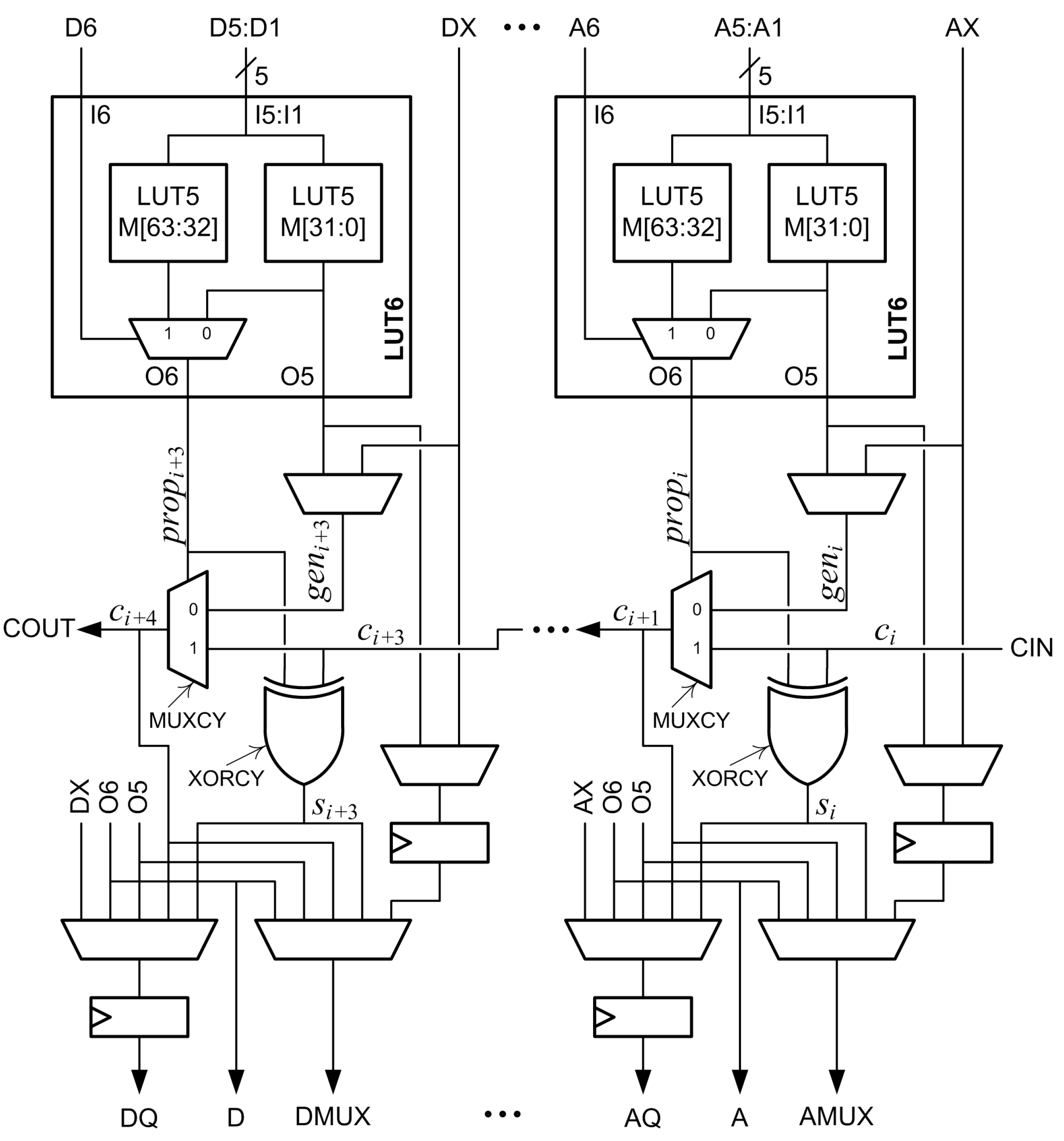
The main logic resource for implementing combinational and sequential circuits in a Xilinx FPGA is the configurable logic block (CLB). Each CLB has two slices. Figure 1 is a partial diagram of a 7 Series FPGA slice. Each slice has four 6-input lookup tables (LUT6s) designated A, B, C, and D. Each LUT6 is composed of two 5-input lookup tables (LUT5s) and a 2-to-1 multiplexer. The two LUT5s are memories that share five inputs designated I5:I1. The memory values are designated M[63:32] in one LUT5 and M[31:0] in the other LUT5. The output of the M[31:0] LUT5 is designated O5. The sixth input, I6, is input to a multiplexer that selects one of the LUT5 outputs. The selected output is designated O6. The LUT6 is normally configured as either two LUT5s with five shared inputs and two outputs by connecting I6 to logic ‘1’, or as one LUT6 with six inputs and one output by connecting the sixth input to I6 [17,18].
A multiplexer (MUXCY) and an XOR gate (XORCY) are associated with each LUT6. Inputs to the MUXCY associated with the A LUT6 are a select signal, , a first data input, , and a second data input, . The output of the MUXCY, , is connected to the MUXCY associated with the B LUT6. These connections continue through the C and D LUT6s to form a fast carry chain within the slice. The output of the slice, COUT, can be connected to the input of the next slice, CIN, to form longer carry chains. The signal is driven by the O6 output of the corresponding LUT6. The signal is selected by a configuration multiplexer and is either the O5 output of the corresponding LUT6 or the bypass input, which is designated AX, BX, CX, or DX.
Two flip-flops are associated with each LUT6. One flip-flop can be used to register O5 or the bypass input. The other flip-flop can be used to register O5, O6, the bypass input, the MUXCY output, or the XORCY output.
2.2. Proposed Two-Operand Adder
Suppose X and Y are to be added using the Xilinx fast carry logic. For the column of the adder, and are the bits of X and Y, respectively, is the carry-in bit, is the carry-out bit and is the sum bit. The signal must be set to and the signal can be set to either or to add and [14,16]. If and together are a function of five or fewer inputs, then the LUT6 can be configured as two LUT5s, generating either or at O5 and routing it to , and generating at O6 to drive . If and together are a function of six inputs, then the LUT6 can be configured to generate at O6 to drive and or can be applied to the bypass input and configured to drive the input. A disadvantage to this configuration is that the bypass flip-flop cannot be used.
Normally, a LUT6 can be used to either generate a function of six inputs at O6 or to generate two functions of five inputs at O5 and O6 [17,18]. However, in some cases, one function of six variables can be output at O6 and a separate function of five shared variables can be output at O5. Suppose is a function of one variable connected to I6 and is a function of five variables connected to I5:I1. The function is stored in M[31:0], so is output at O5. If is ‘0’, is also output at O6. If is ‘1’, the function stored in M[63:32] is output at O6. If is stored in M[63:32] then is generated at O6 and is generated at O5. This can be used to add and without using the bypass input when is a function of one variable and is a function of up to five variables. Figure 2 shows the connections for this configuration. This frees the bypass input to be connected to the bypass flip-flop to implement additional registers. Input I6 has the shortest delay path and I1 has the longest [17], so this method also allows faster inputs to be used. The carry into the proposed adder, , can be used to implement subtraction or to add an extra bit to the least significant column.
3. Proposed Constant-Coefficient Multipliers
This section describes how the proposed constant-coefficient multipliers (KCMs) are implemented and pipelined.
3.1. Radix-2 Multiplication by a Constant
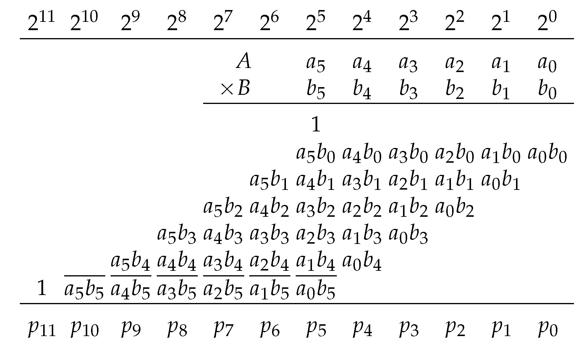
Suppose A is an m-bit constant, B is an n-bit variable and is to be computed. If A and B are unsigned integers, then
and the product is
If A is positive and B is signed, then
and the product can be computed using Baugh and Wooley’s approach [19] as
Figure 3 shows a ()-bit KCM, where A is a positive constant and B is a two’s-complement variable as described by Equation (6). The least-significant column has a weight of to simplify equations and column references, but the results in this work are applicable to fixed-point multipliers by applying appropriate shifts and placement of the binary point.
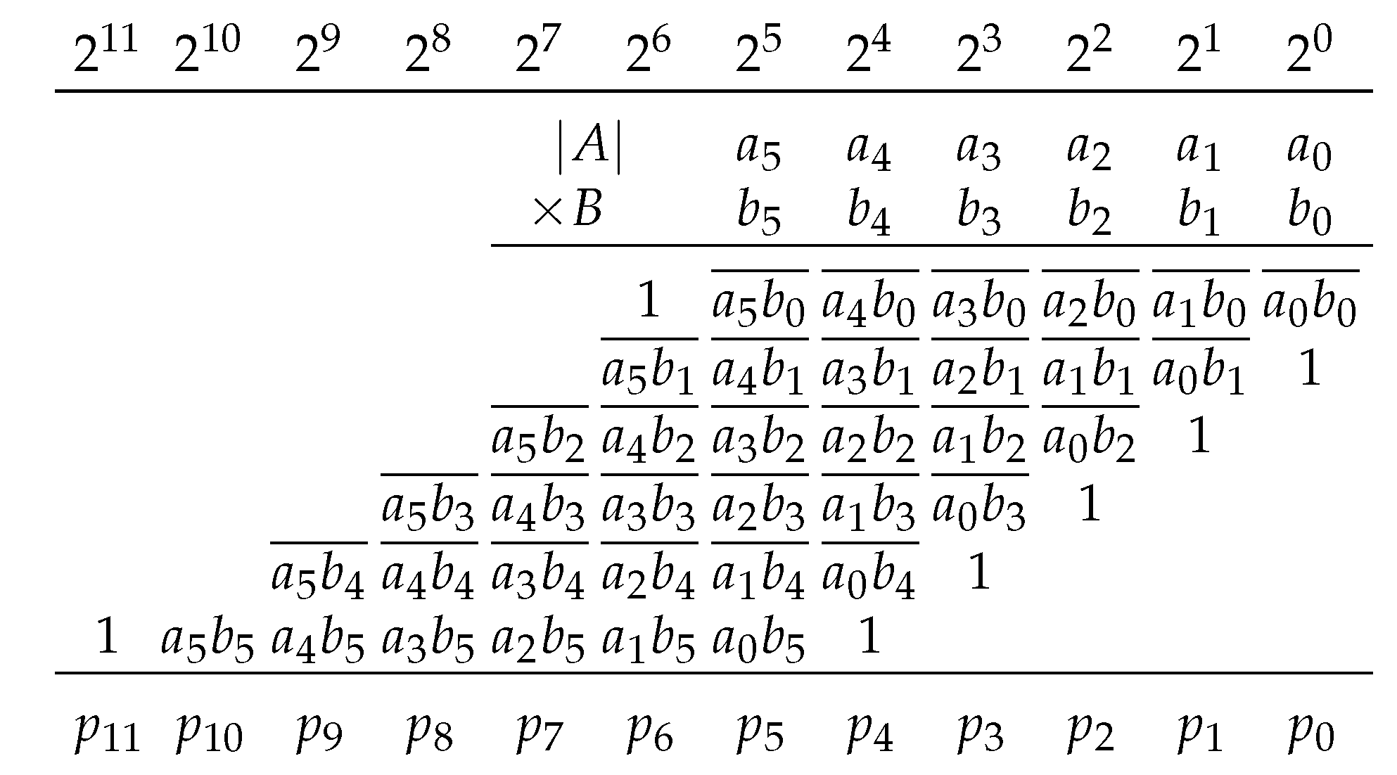
If A is negative, it could be coded in two’s complement form and Baugh and Wooley’s approach could be used to develop an equation for the product. A would have bits of useful precision instead of m bits because the most-significant bit (MSB) would always be ‘1’. In the proposed designs, the magnitude of A is used with an implicit negative sign bit and Equation (3) is used if B is unsigned or Equation (6) is used if B is signed. The product is then negated by negating each row of partial products. Each bit, including implicit leading ‘0’s, is complemented and ‘1’ is added to the least-significant bit (LSB) in each row. The constants are then pre-added to simplify the matrix. If A is negative and B is unsigned, then
The product is bits to accommodate the sign bit. The product is always negative so the MSB is always ‘1’ and does not require any logic. If A is negative and B is signed, then
The product is bits assuming . If a hard-wired shift and negation of the product would be used instead of a KCM.
3.2. Design of Proposed Constant-Coefficient Multiplier
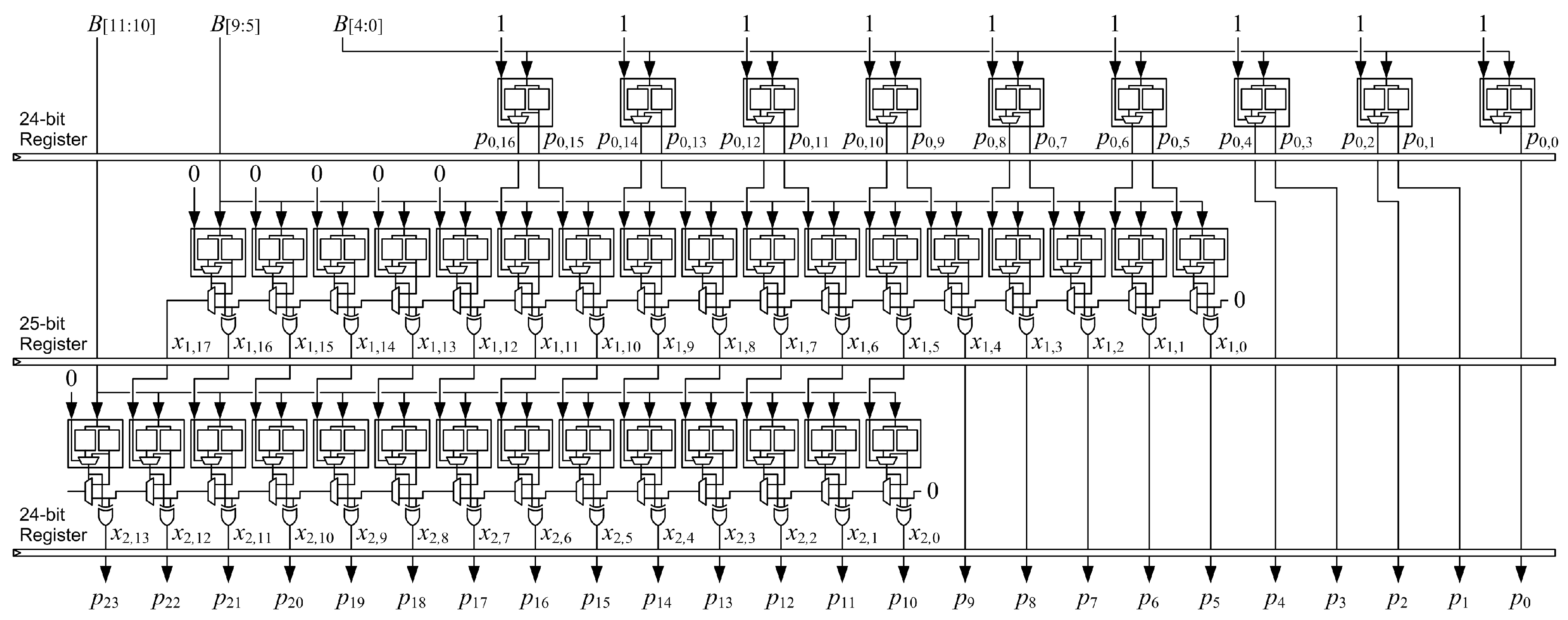
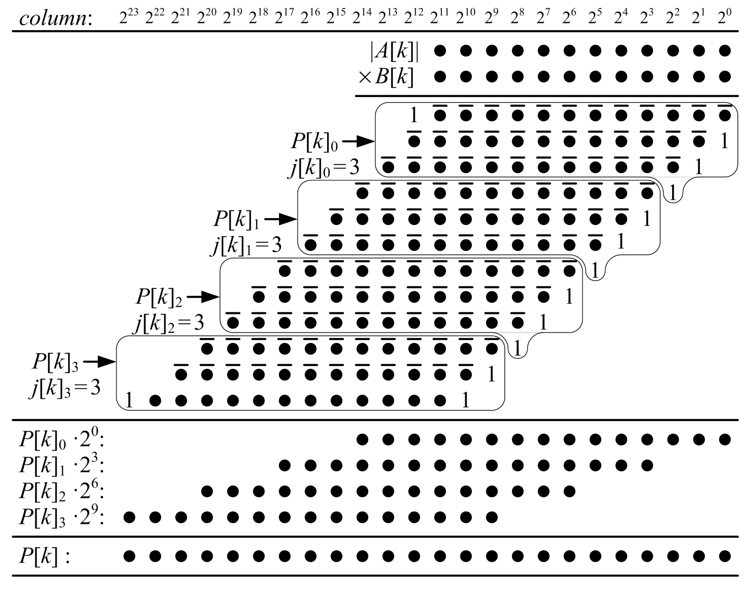
Figure 5 shows a dot diagram of a proposed ()-bit KCM, where A is a negative constant and B is a two’s complement variable. Each dot is a partial-product bit that corresponds to a bit in Equation (8). Each row j of partial-product bits is a function of only one variable bit, . The rows of partial-product bits are divided into groups, each of which are summed to produce a partial product, . Each partial product is the sum of rows of partial-product bits.
In the example of Figure 5, the first five rows of partial-product bits are grouped and their sum is . is a function of the constant A, the constant and a 5-bit sub-vector of the variable B, B[4:0]. The possible values of are pre-computed and generated using LUT6s. Each LUT6 generates two bits of , and . The next five rows of partial-product bits are grouped and their sum is , which is a function of A, and B[9:5]. The possible values of are pre-computed and generated by a proposed two-operand adder, which adds the generated value to and produces an accumulated sum, . The final two rows of partial-product bits are grouped and their sum is , which is a function of A, and B[11:10]. The possible values of are pre-computed, generated by another proposed two-operand adder, and added to to produce an accumulated sum . The five least-significant bits of the final product, P[4:0], are the five LSBs of . The next five LSBs of the product, P[9:5], are the five LSBs of the accumulated sum . The remaining bits of the product, P[23:10], are the accumulated sum, .
In a proposed ()-bit KCM, all of the partial-product bits are grouped into partial products. Each partial product, , is the sum of rows of partial-product bits. When is an exact multiple of five, such as when , is the sum of six rows and each of the other partial products are the sum of five rows. When is not an exact multiple of five, each partial product is the sum of five rows except possibly the last, which is the sum of the remaining rows.
is the sum of the first rows of partial-product bits and is generated using LUT6s. When is the sum of six rows, each bit is a function of six variables, B[5:0], so each LUT6 generates one output bit. When is the sum of five rows, each pair of bits and are functions of the same five variables, B[4:0], so each LUT6 generates two output bits. is bits long, so LUT6s are required if and LUT6s are required if .
The remaining partial products, where , are each generated using a proposed two-operand adder. The proposed two-operand adder generates a function of up to five variables, so it is most efficient when is the sum of five rows of partial-product bits. is bits long, so LUT6s are required for each two-operand adder.
Constant ‘1’s can be grouped with any partial product and are simply included in each pre-computed value. In practice, groups are selected so that constant ‘1’s do not increase the length of the partial product.
When is an exact multiple of five, each partial product requires LUT6s. There are partial products, and , so the maximum number of required LUT6s is
When is not an exact multiple of five, there are LUT6s instead of LUT6s in the first row, so the maximum number of required LUT6s is
Some LUTs may be optimized away during synthesis, so these equations give the maximum number of required LUT6s.
3.3. Array Structure and Pipelining
Figure 6 shows the structure of the proposed ()-bit KCM from the example of Figure 5. The top row of LUT6s generates the first five rows of partial-product bits and outputs the sum, . The second row of LUT6s implements a proposed two-operand adder that generates the sum of the next five rows of partial-product bits, , and adds it to to produce an accumulated sum, . The third row of LUT6s implements another two-operand adder that generates the sum of the last two rows of partial-product bits, , and adds it to to produce an accumulated sum, . The KCM output, P, is composed of the five LSBs of , the five LSBs of and .
The proposed KCM can be pipelined by placing registers after each row of LUT6s. The first stage registers bits of the final product P and bits of B, which requires flip-flops. Subsequent stages register bits of , additional bits of P and fewer bits of B, which requires flip-flops. The last stage registers the output P, which requires flip-flops. There are stages, and each stage registers bits except the first and last stages, which register bits each, so the maximum number of flip-flops required is
Each LUT6 used in the KCM has two available flip-flops so there are more than enough flip-flops available within the footprint of the multiplier to implement pipeline registers. The structure is very regular and easy to place in the logic fabric so that routing paths are short and fast.
3.4. Discussion
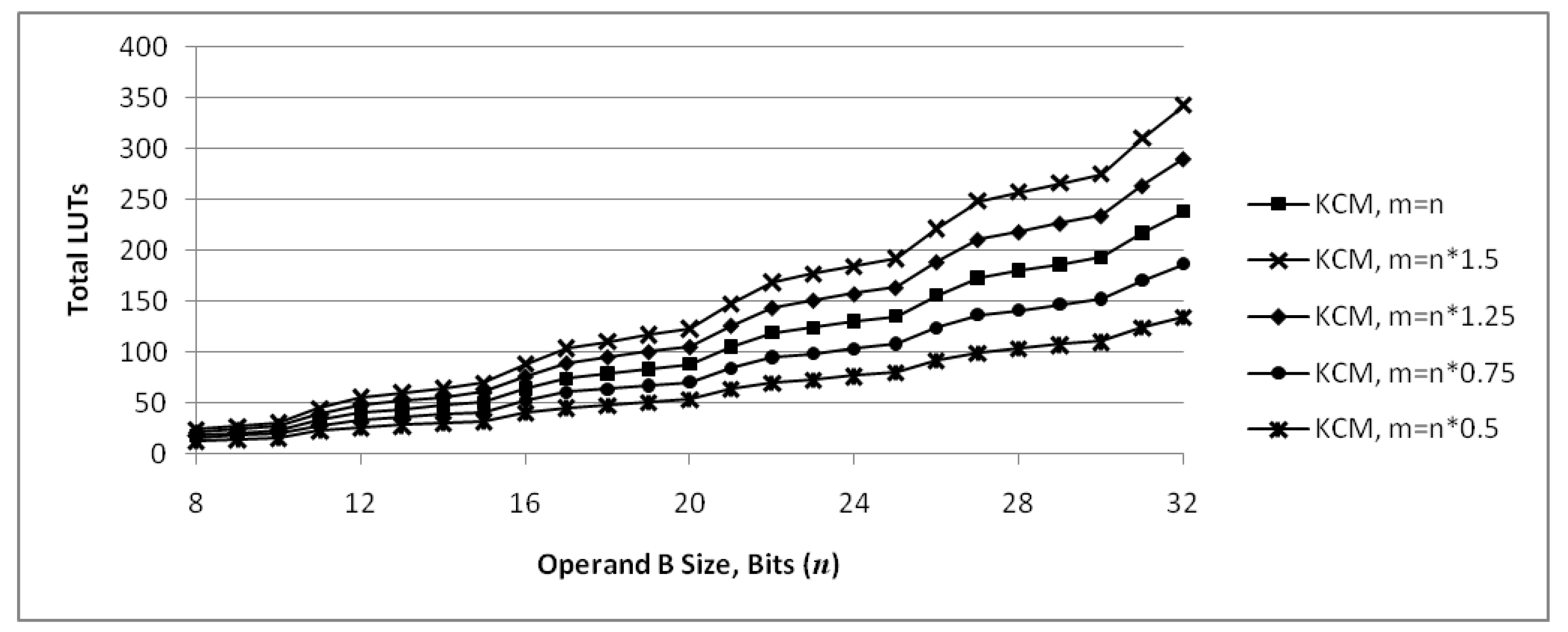
When , the first row of the KCM computes the sum of five partial products using LUT6s. Each LUT6 computes two bits of the sum, except for one LUT6 that computes only one bit if m is even. The second row of the KCM also computes the sum of five partial products and adds them to the sum from the first row. This is very efficient because both rows are computing the maximum number of partial-product bits per LUT6. When n is increased to , the second row still computes the sum of five partial products, but the first row now computes the sum of six partial products, so each LUT6 only computes one bit of the sum. This causes a jump in the number of LUTs required to implement the KCM. When n is increased to , the first row computes the sum of five partial products, which reduces the number of LUT6s in that row compared to . The second row still computes the sum of five partial products. However, a third row is now required, which causes another jump in the number of LUTs required to implement the KCM. When n is increased to , the first and second rows still compute the sum of five partial products each. The third row computes the sum of three partial products, compared to two for , which only requires one additional LUT6 plus an additional LUT6 per bit that m increases, so the increase in the number of LUTs required to implement the KCM is not as large as the increase from to or from to . The situation is similar when n is increased to and again when n is increased to . When n is increased to , the first row computes the sum of six partial products, which causes a jump in the number of required LUTs as it does when n increases from to . This cycle repeats itself as n is increased. The significance of this is that for a given value of m, KCMs with are generally the most efficient in terms of required LUTs, while KCMs with are generally the least efficient.
The value of m does not affect the number of rows in the KCM, so there are no jumps in the required number of LUTs as m is increased. If is an exact multiple of five, there are rows in the KCM and the first row requires one LUT6 per bit of the sum. As m is increased, each row of the KCM requires one additional LUT6 per bit that m increases, so a total of additional LUT6s are required. If is not an exact multiple of five, there are rows in the KCM and the first row requires approximately one half of an LUT6 per bit of the sum. As m is increased, the KCM requires approximately one half of an additional LUT6 for the first row and one additional LUT6 for each of the other rows per bit that m increases, so a total of additional LUT6s are required per bit that m increases. The significance of this is that, for a given value of n, the increase in the number of LUTs required to implement the KCM as m increases is approximately linear, and the value of m has a much lower impact than n on the efficiency of the implementation in terms of required LUTs.
Figure 7 shows the number of LUT6s required for KCMs as m and n are varied, based on Equations (9) and (10). These functions are discrete and the points are connected by lines for readability only, not to imply continuity. The middle set of points is the case where . The total number of LUTs required for the KCM increases as increases, with jumps from to , from to , etc., due to n increasing as discussed earlier. The other sets of points are cases where . This results in m having a fractional value for many points, which is not possible. However, those fractional values are used to compute the points because the intent of the graph is to show how the number of LUTs scales with m, not to show an exact number of LUTs. The graph shows that for a given value of n, the change in the number or LUTs required is roughly proportianal to .
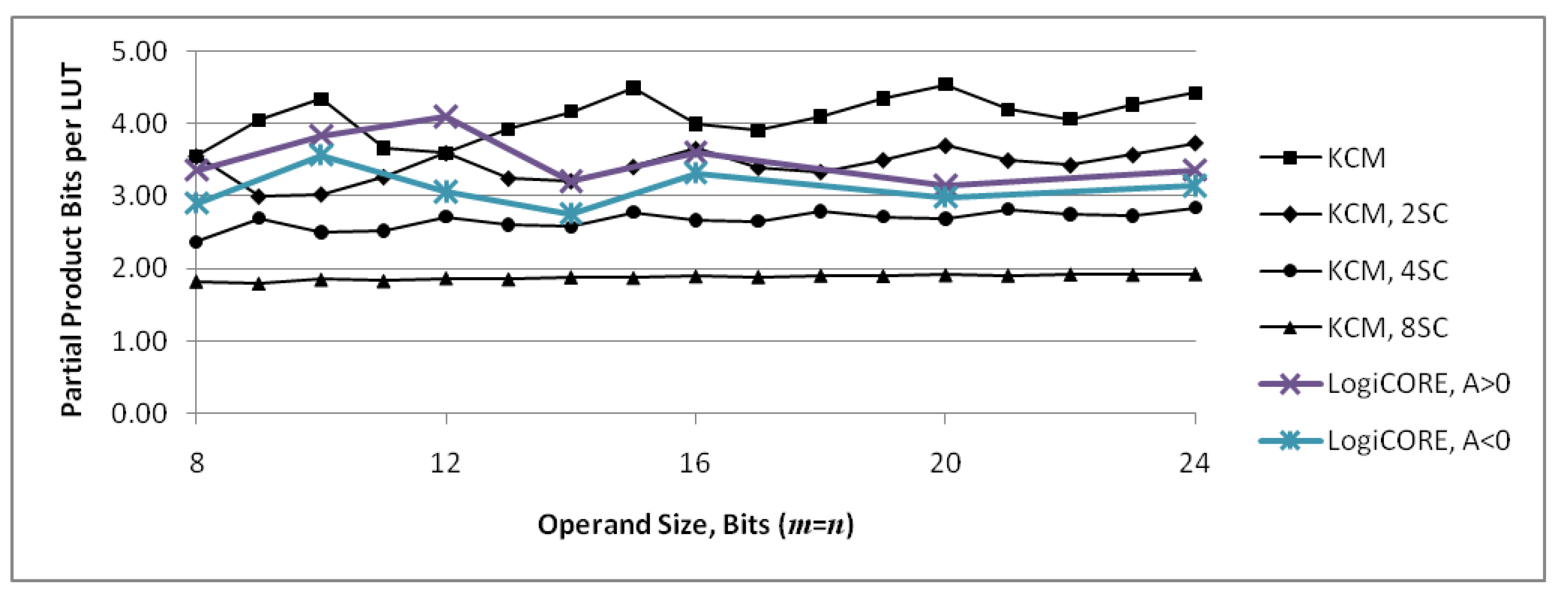
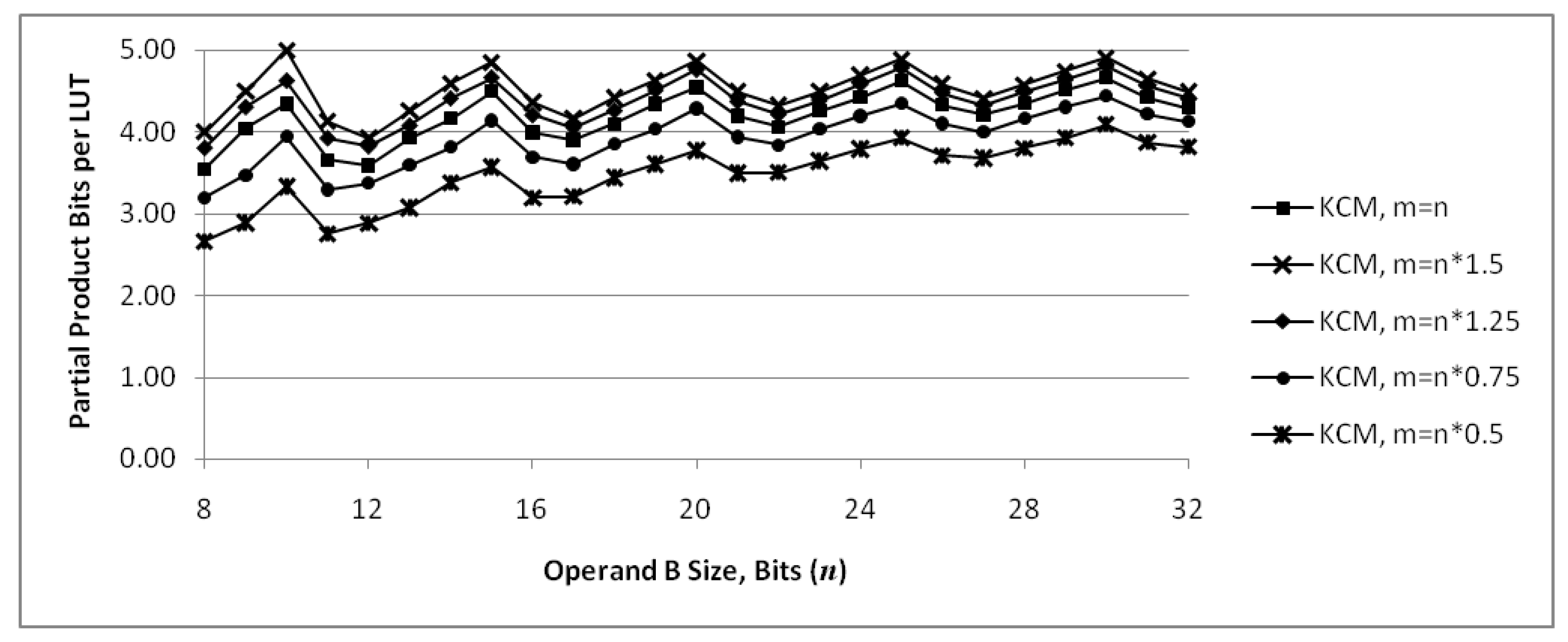
Figure 8 shows the number of partial product bits that are computed and summed, , per LUT6 required for implementation as m and n are varied. This provides a measure of efficiency of the implementation in terms of LUTs required. The middle set of points is the case where . The graph shows that KCMs with generally have a local maximum value and are the most efficient, while KCMs with generally have a local minimum value and are the least efficient. For a given value of n, efficiency increases somewhat as m increases and decreases as m is decreased.
4. Proposed KCMs with Selectable Coefficients
Turner and Woods present a reduced-coefficient multiplier (RCM) that can operate on a limited set of coefficients, selectable at run-time [10]. Their multipliers use canonical signed digit (CSD) recoding and sub-expression elimination to reduce the number of add/subtract operations. This section discusses how the proposed KCMs can be modified to incorporate the idea to operate on a set of two, four or eight coefficients, selectable at run-time.
In the following sections, the selectable coefficients are designated and the resulting products are designated . The coefficients for a KCM with selectable coefficients do not need to have the same sign. The variable is designated because it can be treated as signed for one coefficient and unsigned for another. For example, a KCM with two selectable coefficients could treat as negative and as unsigned, and treat as positive and as signed without any special considerations.
4.1. Proposed KCMs with Two Selectable Coefficients
A KCM with two selectable coefficients requires one input to select the coefficient. Partial products for both coefficients are pre-computed and generated using LUT6s for each , and generated using proposed two-operand adders for the rest of the partial products, .
One input to each LUT6 used to generate is needed to select the coefficient, so only five inputs are left to select the pre-computed value of if each LUT6 generates one bit, , and only four inputs are left if each LUT6 generates two bits, and . One of the inputs to each LUT6 in each of the adders are needed to select the coefficient, so only four inputs are left to select the pre-computed value of . Therefore, all of the partial-product bits in a KCM with two selectable coefficients are grouped into partial products.
When is an exact multiple of four, each partial product requires LUT6s. There are partial products, and , so the maximum number of required LUT6s is
When is not an exact multiple of four, there are LUT6s instead of LUT6s in the first row, so the maximum number of required LUT6s is
Some LUTs may be optimized away during synthesis, so these equations give the maximum number of required LUT6s.
Figure 9 shows a dot diagram of a proposed ()-bit KCM with two selectable coefficients, where is a negative constant and is a two’s complement variable (cf. Figure 5). In this example, no additional adders are needed and the unit has a very similar footprint to the single-coefficient KCM. Other size operands usually require one or more additional adders.
4.2. Proposed KCMs with Four Selectable Coefficients
A KCM with four selectable coefficients requires two inputs to select the coefficient. Partial products for each coefficient are pre-computed and generated using LUT6s for each and the proposed two-operand adders generate and add the rest of the partial products.
Two inputs to each LUT6 used to generate are needed to select the coefficient, so only four inputs are left to select the pre-computed value of if each LUT6 generates one bit and only three inputs are left if each LUT6 generates two bits. Two of the inputs to each LUT6 in each of the adders are needed to select the coefficient, so only three inputs are left to select the pre-computed value of . Therefore, all of the partial-product bits in a KCM with four selectable coefficients are grouped into partial products.
When is an exact multiple of three, the maximum number of required LUT6s is
When is not an exact multiple of three, the maximum number of required LUT6s is
4.3. Proposed KCMs with Eight Selectable Coefficients
A KCM with eight selectable coefficients requires three inputs to select the coefficient. Partial products for each coefficient are pre-computed and generated using LUT6s for each and the proposed two-operand adders generate and add the rest of the partial products.
Three inputs to each LUT6 used to generate are needed to select the coefficient, so only three inputs are left to select the pre-computed value of if each LUT6 generates one bit and only two inputs are left if each LUT6 generates two bits. Three of the inputs to each LUT6 in each of the adders are needed to select the coefficient, so only two inputs are left to select the pre-computed value of . Therefore, all of the partial-product bits in a KCM with eight selectable coefficients are grouped into partial products.
When is an exact multiple of two, the maximum number of required LUT6s is
When is not an exact multiple of two, the maximum number of required LUT6s is
4.4. Discussion
Table 1 compares proposed KCMs that have a single coefficient to the proposed KCMs with two, four and eight selectable coefficients. The number of partial products and the number of LUTs used by each version are given, based on Equations (12) through (17). The percentage increase in the number of LUTs for two, four and eight-coefficient versions versus single-coefficient versions is also given. One or more of the LUTs used to generate the least-significant bits in the first row can often be optimized away so the number of LUTs in an actual implementation may be a little lower. For the operand sizes in the table, KCMs with two selectable coefficients use an average of 19% more LUTs, KCMs with four selectable coefficients use an average of 55% more LUTs and KCMs with eight selectable coefficients use an average of 117% more LUTs than single-coefficient KCMs. In designs where a KCM with selectable coefficients can replace two or more single-coefficient KCMs, the increase is more than offset by the reduced number of KCMs required.
KCMs with selectable coefficients usually have more partial products than single-coefficient KCMs. This means more adder stages are required, which translates into additional delay in single-cycle units. In pipelined versions, this results in longer latencies. However, cycle times are comparable because the adders are the same width or a little shorter.
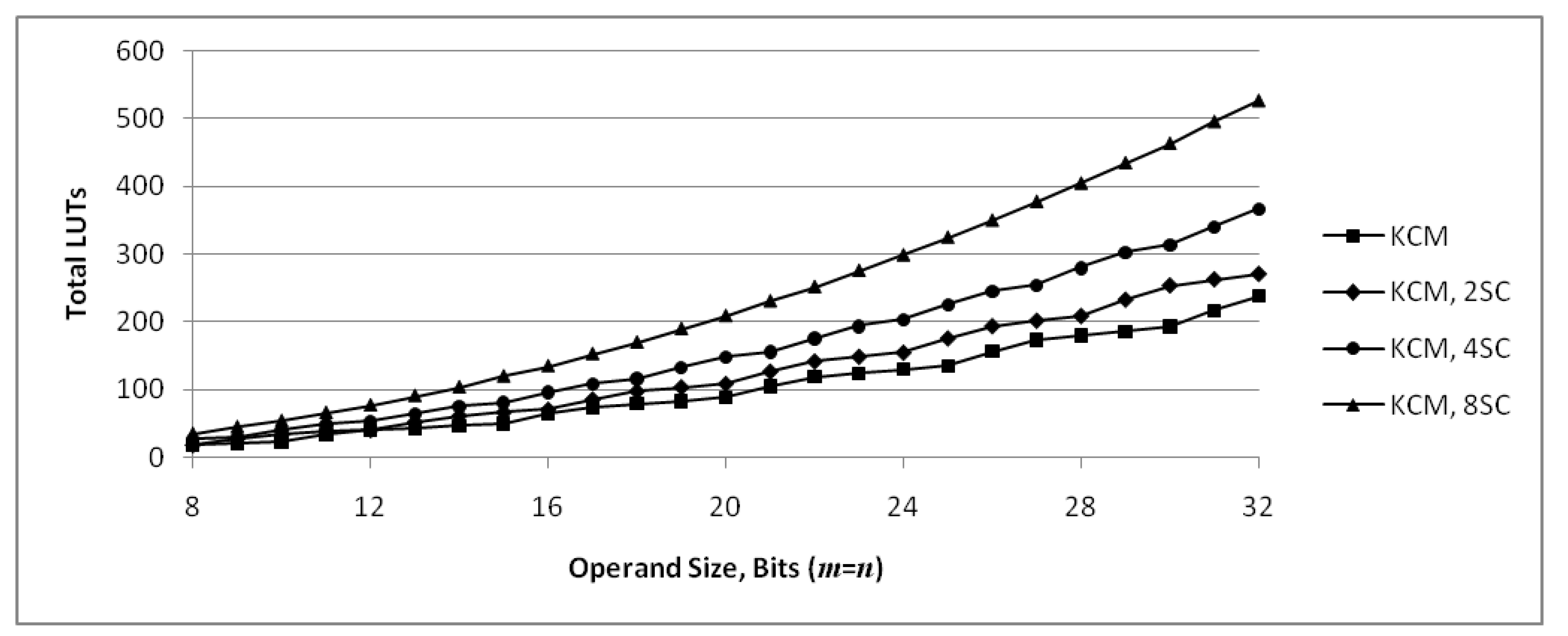
Figure 12 shows the number of LUT6s required for KCMs with one, two, four and eight selectable coefficients. These functions are discrete and the points are connected by lines for readability only, not to imply continuity. The lower set of points is for single-coefficient KCMs and is the same as the middle set of points in Figure 7. As discussed in Section 3.4, there are jumps at every fifth value of n, starting with , because the first row requires twice as many LUT6s every fifth value of n starting at and the number of rows increases every fifth value of n starting at . KCMs with two selectable coefficients have jumps for the same reasons, except they occur every fourth value of n, KCMs with four selectable coefficients have jumps every third value of n and KCMs with eight selectable coefficients have jumps every second value of n.
Figure 13 shows the number of partial product bits that are computed and summed for a single output per LUT6 for KCMs with one, two, four and eight selectable coefficients. The upper set of points is for single-coefficient KCMs and is the same as the middle set of points in Figure 8. As discussed in Section 3.4, there are local maximums every fifth value of n starting at and local minimums every fifth value of n starting at , indicating most efficient and least efficient units, respectively. KCMs with two selectable coefficients have a similar cycle every fourth value of n. They can be implemented using the same number of LUTs as single-coefficient KCMs for and because of the different period of each cycle. The cycle for KCMs with four selectable coefficients is every third value of n and the cycle for KCMs with eight selectable coefficients is every second value of n. KCMs with selectable coefficients are less efficient than single-coefficient KCMs by this measure because they require more LUTs to produce a single product in a clock cycle. However, they are more efficient in a design that performs time-multiplexed multiplication because additional single-coefficient KCMs or a general-purpose multiplier would be required to provide the same functionality.
5. Results
The proposed KCMs are compared to Xilinx LogiCORE IP v12.0 (rev. 12) (Xilinx Inc., San Jose, CA, USA) constant-coefficient multipliers [20] for -bit units. Proposed KCMs with two, four and eight selectable coefficients are compared to units composed of a LogiCORE IP general-purpose multiplier and a lookup function to select the coefficient. Proposed KCMs with two and four selectable coefficients are also compared to units composed of two or four LogiCORE IP KCMs and a multiplexer to select the output. Results for 8, 10, 12, 14, 16, 20 and 24-bit operands are given for single-cycle and pipelined units. KCMs are synthesized with a positive constant and again with a negative constant. KCMs with selectable coefficients are synthesized with half of the constants being positive and the other half negative.
Arbitrary values , , and are used for constants. This paper presents operands as integers, so is multiplied by , and are multiplied by , and is multiplied by . They are rounded to the nearest odd to ensure that the least-significant bit (LSB) is ‘1’ to avoid obvious optimizations. Table 2 gives the magnitudes of the constants used in synthesized units. Examination of the bit patterns show that they are typical of many constants, with some runs of ‘1’s and ‘0’s and some isolated ‘1’s and ‘0’s.
5.1. Methodology
Version 2016.3 of the Xilinx Vivado Design Suite (Vivado) was used. Designs were synthesized with the strategy set to ‘Flow_PerfOptimized_high’ and implemented with the strategy set to ‘Performance_Retiming’. Designs were synthesized for the Xilinx Virtex-7 XC7VX330T-FFG1157 (-3 speed grade) device with a timing constraint of 1 ns on the inner clock. All results are post place-and-route.
LogiCORE IP constant-coefficient multipliers and general-purpose multipliers were created using the IP Catalog in Vivado. Structural models of the proposed multipliers were implemented in Verilog-2001 (IEEE Standard 1364-2001, IEEE, Piscataway, NJ, USA). Pipelined versions were created for LogiCORE IP multipliers using the optimal number of stages specified in the IP customization dialog. Input and output (I/O) ports were double registered to reduce dependence on I/O placement [21]. A separate clock on the inner level was used to measure the delay through each multiplier.
5.2. SynthesisResults
Synthesis results for proposed KCMs are given Section 5.2.1. Synthesis results for proposed KCMs with two, four and eight selectable coefficients are given in Section 5.2.2, Section 5.2.3 and Section 5.2.4, respectively.
5.2.1. Proposed Constant-Coefficient Multipliers
Synthesis results for single-cycle constant-coefficient multipliers are given in Table 3 and Table 4. The total number of LUTs used and the delay are given. The LUT-delay product (LDP), computed by multiplying the number of LUTs by the delay, is also given. LDP is analogous to the area-delay product of a very-large-scale integration (VLSI) design. The reciprocal of LDP gives a metric to compare maximum throughput. The total number of LUTs, delay and LDP are normalized to LogiCORE IP KCMs.
Table 3 gives results for single-cycle KCMs, where the constant A is positive and the variable B is signed. For these units, proposed designs are 10% to 31% smaller than comparable LogiCORE IP KCMs, except for 12-bit units which are 14% larger. This anomaly occurs because proposed KCMs are less efficient for as discussed in Section 3.4 and LogiCORE IP KCMs with positive coefficients are more efficient for as shown in Figure 15. Proposed designs have a 23% to 108% increase in delay, so there is a trade-off of fewer LUTs for increased cycle time. Table 4 gives results for single-cycle KCMs where the constant A is negative and the variable B is signed. For these KCMs, LogiCORE IP units increase in size while proposed units remain roughly the same. This reduces the relative size, so proposed designs with a negative constant are 17% to 35% smaller than LogiCORE IP units. Normalized delay is similar to proposed KCMs with a positive constant.
For most proposed single-cycle units, the normalized LDP is greater than 1.0. This suggests that single-cycle LogiCORE IP units usually offer higher throughput in designs where the KCMs are on the critical path and determine the clock period. However, when the KCMs are not on the critical path and proposed designs meet timing requirements, proposed designs for most operand sizes will improve the system by reducing the number of LUTs required.
Synthesis results for pipelined constant-coefficient multipliers are given in Table 5 and Table 6. The number of pipeline stages are reported, as well as the total number of LUTs used, the delay and the LUT-delay product. The number of pipeline stages determines the latency in clock cycles. The reported delay is for one clock cycle. The total number of LUTs, delay and LDP are normalized to LogiCORE IP units.
Table 5 gives results for pipelined KCMs, where the constant A is positive and the variable B is signed. For these units, proposed designs are 15% to 36% smaller than comparable LogiCORE IP units, except for 12-bit units which are 5% larger. Proposed designs have a 23% to 38% increase in delay so there is still a trade-off of LUTs for cycle time. However, the extreme cases are significantly reduced and normalized delay is fairly constant as operand size is scaled.
Table 6 gives results for pipelined KCMs, where the constant A is negative and the variable B is signed. As with single-cycle KCMs, negative constant LogiCORE IP KCMs increase in size, while proposed units remain roughly the same. This again reduces the relative size, so proposed designs with a negative constant are 20% to 42% smaller than LogiCORE IP units. Even 12-bit units are 20% smaller. Normalized delay is similar to proposed KCMs with a positive constant as it is with single-cycle KCMs.
The average normalized LDP for proposed pipelined KCMs is 1.025 for units with a positive constant and 0.855 for units with a negative constant. The overall average LDP is 0.940 and the overall median LDP is 0.881. This suggests that, for many operand sizes, proposed pipelined KCMs offer higher throughput in designs where they are on the critical path and determine the clock period. When they are not on the critical path and meet timing requirements, the throughput advantage of proposed units increases because they use 27% fewer LUTs on average than comparable LogiCORE IP units. Proposed KCMs have more pipeline stages than some LogiCORE IP KCMs, especially as n gets larger, because the proposed method uses an array structure to add partial products while LogiCORE IP units appear to use a tree structure. This may be a problem for systems where latency requirements are difficult to meet. However, for systems that can tolerate the increased latency this is less of an issue.
Figure 14 combines the graph of Figure 12 with actual values for LogiCORE IP KCMs obtained by synthesis. The graph shows that, for many operand sizes, the proposed KCMs with two selectable coefficients use fewer LUTs than LogiCORE IP KCMs that only handle a single-coefficient.
Figure 15 combines the graph of Figure 13 with actual values for LogiCORE IP KCMs obtained by synthesis. The graph shows that proposed KCMs are more efficient in terms of required LUTs than LogiCORE IP KCMs except for 12-bit units with a positive constant.
Figure 15.
Number of partial product bits computed and summed per LUT6 for KCMs. Values for proposed KCMs are computed maximums, values for LogiCORE are from synthesized results.
Figure 15.
Number of partial product bits computed and summed per LUT6 for KCMs. Values for proposed KCMs are computed maximums, values for LogiCORE are from synthesized results.
5.2.2. Proposed KCMs with Two Selectable Coefficients
Synthesis results for single-cycle KCMs with two selectable coefficients are given in Table 7. Results for units composed of a LogiCORE IP general-purpose multiplier and a lookup function to select the coefficient are given. Results for units composed of two LogiCORE IP KCMs with a multiplexer to select the output are also given. Results are normalized to LogiCORE IP KCM units because they use 27% fewer LUTs and are 2.08 times faster on average than LogiCORE IP multiplier units.
Proposed KCMs with two selectable coefficients use only 20% more LUTs on average than proposed KCMs with a single coefficient, while units based on LogiCORE IP KCMs use more than twice as many LUTs because they cannot be combined and require a multiplexer to select the product. Delay for proposed 8- and 12-bit units is about the same but increases for other sizes because an additional row is required to compute the product. Delay for all LogiCORE IP KCM-based units increases due to the multiplexer and because the variable operand must be routed to two KCMs, which doubles the fanout. Proposed units use 57% to 70% fewer LUTs compared to LogiCORE IP KCM-based units at the expense of a 13% to 74% increase in delay. The LDP for proposed units is 28% to 67% lower, indicating that significantly higher throughput can be achieved compared to LogiCORE IP KCM-based units. LogiCORE IP multiplier-based units are not competitive for two selectable coefficients.
Table 8 gives synthesis results for pipelined KCMs with two selectable coefficients. Proposed units use the same number of LUTs as single-cycle versions, except for 20 and 24-bit units, which use some additional LUTs as shift registers (SRLs) to replace flip-flops. This optimization can be avoided if desired using the -shreg_min_size setting in synthesis options. Similar to single-cycle units, proposed designs use 60% to 70% fewer LUTs than LogiCORE IP KCM-based units. However, proposed units benefit relatively more from pipelining than LogiCORE IP and are only 3% to 37% slower, and the relative delay tends to improve as n increases. Proposed units have 45% to 63% lower LDP, which is consistently lower for all operand sizes. The LDP suggests that proposed units offer more than double the throughput versus LogiCORE IP KCM-based units for most operand sizes. LogiCORE IP multiplier-based units are still not competitive.
5.2.3. Proposed KCMs with Four Selectable Coefficients
Table 9 gives synthesis results for single-cycle KCMs with four selectable coefficients. Proposed KCMs with four selectable coefficients use 31% more LUTs on average than proposed KCMs with two selectable coefficients. LogiCORE IP KCM-based units with four coefficients use 82% more LUTs while LogiCORE IP multiplier-based units use only 1% more LUTs on average than their two coefficient versions. Delay increases for proposed units and LogiCORE IP KCM-based units and remains about the same for LogiCORE IP multiplier-based units. Results are normalized to LogiCORE IP multiplier-based units.
Proposed single-cycle units use 61% to 67% fewer LUTs than LogiCORE IP multiplier-based units and 69% to 74% fewer LUTs than LogiCORE IP KCM-based units. Proposed units are faster than some LogiCORE IP multiplier-based units and slower than some, but are slower than LogiCORE IP KCM-based units for all sizes. Proposed units have a 58% to 81% lower LDP than LogiCORE IP multiplier-based units and a 44% to 67% lower LDP than LogiCORE IP KCM-based units.
Table 10 gives synthesis results for pipelined KCMs with four selectable coefficients. Proposed units benefit relatively more than LogiCORE IP KCM-based and multiplier-based units in regards to delay. They are faster than most LogiCORE IP multiplier-based units and slower than LogiCORE IP KCM-based units but more comparable than they were for single-cycle units. Proposed pipelined units use 61% to 66% fewer LUTs than LogiCORE IP multiplier-based units and 72% to 76% fewer LUTs than LogiCORE IP KCM-based units. They have a 63% to 72% lower LDP than LogiCORE IP multiplier-based units and a 63% to 76% lower LDP than LogiCORE IP KCM-based units.
5.2.4. Proposed KCMs with Eight Selectable Coefficients
Table 11 gives synthesis results for single-cycle KCMs with eight selectable coefficients and Table 12 gives synthesis results for pipelined KCMs with eight selectable coefficients. Results for LogiCORE IP KCM-based units are not given because they would require eight KCMs and do not scale well as the number of coefficients increase. LogiCORE IP multiplier-based units only require a small amount of additional logic for the lookup function so they scale very well.
Proposed units use 51% to 52% fewer LUTs than LogiCORE IP for single-cycle units. They are slower than LogiCORE IP for most units, and the relative delay generally increases as n increases. The LDP for proposed single-cycle units is 13% to 53% lower than LogiCORE IP, with better results for smaller operand sizes.
Proposed pipelined units use 46% to 52% fewer LUTs and are faster, having 10% to 16% lower delay than LogiCORE IP. The LDP for proposed units is 51% to 59% lower than LogiCORE IP and performance is consistently better for all operand sizes.
5.3. Comparison to Möller Et Al.
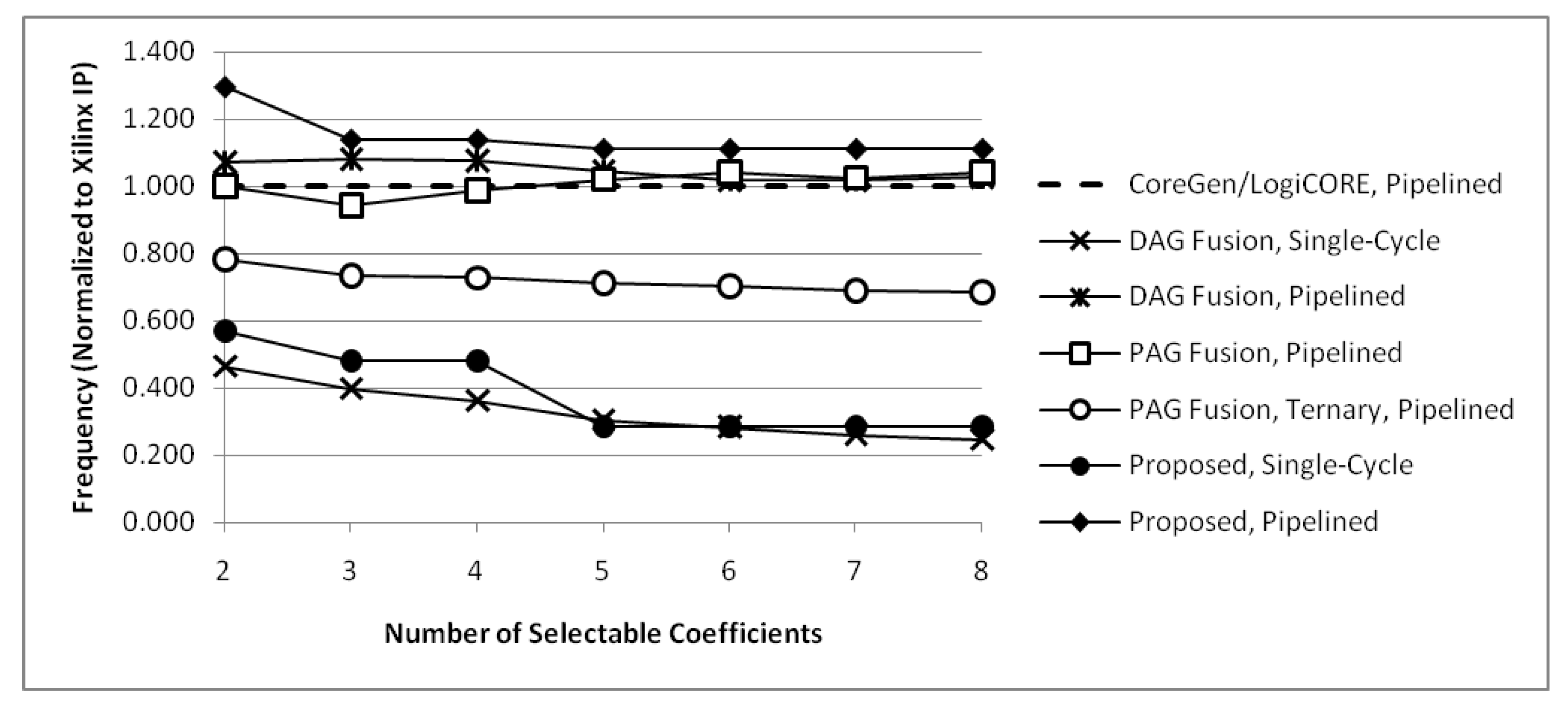
Möller et al. [13] present synthesis results for ()-bit constant coefficient multipliers with two to fourteen selectable coefficients. They compare units generated using their proposed PAG fusion heuristic to units based on DAG fusion [11], using a Xilinx CoreGen multiplier with a distributed RAM to store coefficients as a baseline for comparison. Results for pipelined PAG fusion with ternary adders and PAG fusion with only two-operand adders are given. Results for single-cycle DAG fusion are given, as well as pipelined DAG fusion with resigters after each adder, subtractor, adder/subtractor and multiplexer, plus additional registers as needed for pipeline balancing. The Xilinx CoreGen multiplier-based unit is pipelined to the same depth as pipelined PAG fusion units. The number of slices required for implementation are shown on one graph and the maximum clock frequency for each method is shown on another graph in their paper. Numerical values are estimated from these graphs and tabulated in Table 13 and Table 14 for units with two to eight selectable coefficients.
Results presented by Möller et al. were obtained using Xilinx ISE v13.4, targeting a Virtex 6 FPGA (xc6vlx75t-2ff484-2) [13]. Slices are used as the metric for resource usage, and a Xilinx CoreGen based unit is used as a baseline for comparison. This paper presents results obtained using Xilinx Vivado 2016.3, targeting a Virtex 7 FPGA and uses LUTs as the metric for resource usage. In order to compare results, a Xilinx LogiCORE IP multiplier with a function to lookup coefficients is used in this work as a baseline. The LogiCORE IP multiplier is pipelined to the optimal depth as given in the IP customization dialog and a pipeline register is inserted between the coefficient lookup and the multiplier. Results given by Möller et al. are normalized to their CoreGen based unit and results in this work are normalized to the LogiCORE IP based units to account for differences in the synthesis tools, target device and IP implementation. Table 13 and Table 14 summarize these results.
Figure 16 and Figure 17 compare results from Möller et al. to this work by plotting normalized values. With the proposed approach, a KCM with three selectable coefficients would have the same structure as the KCM with four selectable coefficients described in Section 4.2, except the table of precomputed partial products would use zeros or don’t cares for the unused coefficient. This may allow some LUTs in the first row to be optimized away, but the LUTs in the other rows would still be required so the resources consumed by the unit would be identical or slightly less than a KCM with four selectable coefficients. For this reason, proposed KCMs with three selectable coefficients are graphed using the same values as KCMs with four selectable coefficients. Likewise, proposed KCMs with five, six or seven selectable coefficients are graphed using the same values as KCMs with eight selectable coefficients.
PAG fusion units with two-operand adders use fewer slices than CoreGen for two to four selectable coefficients and PAG fusion units with ternary adders use fewer slices than CoreGen for two to six selectable coefficients. All PAG fusion units use fewer slices than pipelined DAG fusion units. All PAG fusion units with two-operand adders have a maximum frequency comparable to CoreGen units, ranging from 6% slower to 4% faster. PAG fusion units with ternary adders are 22% to 31% slower than CoreGen, mainly because ternary adders are slower than two-operand adders. However, for many applications, they would not be on the critical path and would be better than CoreGen because they use 6% to 60% fewer slices for units with two to six selectable coefficients.
Proposed KCMs with selectable coefficients use significantly fewer slices than LogiCORE IP and pipelined versions are faster than LogiCORE IP for units with two to eight selectable coefficients. PAG fusion units outperform CoreGen units in most cases, so it is important to compare proposed units to PAG fusion units. Table 15 compares required slices and Table 16 compares maximum operating frequency for PAG fusion units, normalized to CoreGen, with proposed units, normalized to LogiCORE IP. These values are then normalized to PAG fusion with two-operand adders and PAG fusion with ternary adders. Comparing normalized values, proposed KCMs with selectable coefficients use 47% to 65% fewer slices than PAG fusion with two-operand adders and 22% to 57% fewer slices than PAG fusion with ternary adders. Proposed KCMs with selectable coefficients can operate 7% to 30% faster than PAG fusion with two-operand adders and 28% to 52% faster than PAG fusion with ternary adders.
6. Conclusions
This paper presents constant-coefficient multipliers (KCMs) for Xilinx FPGAs with 6-input LUTs, and extends them to have two to eight coefficients that may be selected by a control signal at runtime to implement time-multiplexed multiple-constant multiplication. Synthesis results show that proposed KCMs use 20% fewer LUTs for single-cycle designs and 27% fewer LUTs for pipelined designs on average compared to LogiCORE IP KCMs at the expense of increased delay. Proposed KCMs with two to four selectable coefficients use 63% fewer LUTs on average and proposed KCMs with eight selectable coefficients use 49% fewer LUTs on average compared to the smallest LogiCORE IP based alternative. Proposed KCMs with selectable coefficients also outperform state-of-the-art reconfigurable multipliers that are based on shift-and add methods, using 22% to 57% fewer slices than the smallest designs and operate 7% to 30% faster than the fastest designs. For a given operand size and number of constants, proposed designs have the same placement and routing of LUTs, regardless of the sign or magnitude of the constant. The only thing that changes is the content of the LUT RAMs, which makes proposed KCMs an attractive candidate for runtime partial reconfiguration. LogiCORE IP KCMs are larger for negative constants, and the size of KCMs based on shift and add methods vary with the constant, making runtime partial reconfiguration more difficult.
Acknowledgments
The Xilinx Vivado Design Suite was obtained through the Xilinx University Program (XUP). The author wishes to thank the reviewers for their thorough reviews and comments which helped to greatly improve the contributions of this paper.
Author Contributions
EGW designed the proposed units; EGW conceived, designed and performed the experiments; EGW analyzed the data and wrote the paper.
Conflicts of Interest
The author declares no conflict of interest.
Abbreviations
The following abbreviations are used in this manuscript:
| BRAM | Block RAM (Random-Access Memory) |
| CLB | Configurable Logic Block |
| CSD | Canonical Signed Digit |
| DAG | Directed Acyclic Graph |
| DSP | Digital-Signal Processing |
| FPGA | Field-Programmable Gate Array |
| KCM | Constant-Coefficient Multiplier |
| LDP | LUT-Delay Product |
| LSB | Least-Significant Bit |
| LUT | Lookup Table |
| LUT5 | 5-Input Lookup Table |
| LUT6 | 6-Input Lookup Table |
| MSB | Most-Significant Bit |
| PAG | Pipelined Adder Graph |
| RCM | Reduced Coefficient Multiplier |
| PAG | Reduced Pipelined Adder Graph |
References
- Swartzlander, E.E., Jr. Merged Arithmetic. IEEE Trans. Comput. 1980, C-29, 946–950. [Google Scholar] [CrossRef]
- Ercegovac, M. On Approximate Arithmetic. In Proceedings of the 47th Asilomar Conference on Signals, Systems, and Computers, Pacific Grove, CA, USA, 3–6 November 2013; pp. 126–130. [Google Scholar]
- Chapman, K.D. Fast Integer Multipliers Fit in FPGAs; EDN Magazine: AspenCore Media, San Francisco, CA, USA, 1994. [Google Scholar]
- Chapman, K. Constant Coefficient Multipliers for the XC4000E; Version 1.1; Application Note XAPP 054; Xilinx: San Jose, CA, USA, 1996. [Google Scholar]
- Wirthlin, M.J. Constant Coefficient Multiplication Using Look-Up Tables. J. VLSI Signal Process. Syst. Signal Image Video Technol. 2004, 36, 7–15. [Google Scholar] [CrossRef]
- Hormigo, J.; Caffarena, G.; Oliver, J.P.; Boemo, E. Self-Reconfigurable Constant Multiplier for FPGA. ACM Trans. Reconfig. Technol. Syst. 2013, 6, 14:1–14:17. [Google Scholar] [CrossRef]
- Ercegovac, M.; Lang, T. Digital Arithmetic; Morgan Kaufmann: San Francisco, CA, USA, 2004. [Google Scholar]
- Brisebarre, N.; de Dinechin, F.; Muller, J.M. Integer and Floating-Point Constant Multipliers for FPGAs. In Proceedings of the International Conference on Application-Specific Systems, Architectures and Processors (ASAP), Leuven, Belgium, 2–4 July 2008; pp. 239–244. [Google Scholar]
- Gustafsson, O.; Dempster, A.G.; Johansson, K.; Macleod, M.D.; Wanhammar, L. Simplified Design of Constant Coefficient Multipliers. Circuits Syst. Signal Process. 2006, 25, 225–251. [Google Scholar] [CrossRef]
- Turner, R.H.; Woods, R.F. Highly Efficient, Limited Range Multipliers for LUT-Based FPGA Architectures. IEEE Trans. VLSI Syst. 2004, 12, 1113–1117. [Google Scholar] [CrossRef]
- Tummeltshammer, P.; Hoe, J.C.; Püschel, M. Time-Multiplexed Multiple-Constant Multiplication. IEEE Trans. Comput.-Aided Des. Integr. Circuits Syst. 2007, 26, 1551–1563. [Google Scholar] [CrossRef]
- Kumm, M.; Zipf, P.; Faust, M.; Chang, C.H. Pipelined Adder Graph Optimization for high speed multiple constant multiplication. In Proceedings of the 2012 IEEE International Symposium on Circuits and Systems (ISCAS), Seoul, Korea, 20–23 May 2012; pp. 49–52. [Google Scholar]
- Möller, K.; Kumm, M.; Kleinlein, M.; Zipf, P. Reconfigurable Constant Multiplication for FPGAs. IEEE Trans. Comput.-Aided Des. Integr. Circuits Syst. 2017, 36, 927–937. [Google Scholar] [CrossRef]
- Walters, E.G., III. Partial-Product Generation and Addition for Multiplication in FPGAs With 6-Input LUTs. In Proceedings of the 48th Asilomar Conference on Signals, Systems, and Computers, Pacific Grove, CA, USA, 2–5 November 2014; pp. 1247–1251. [Google Scholar]
- Walters, E.G., III. Techniques and Devices for Performing Arithmetic. US Patent Application 15/025,770, 29 March 2016. [Google Scholar]
- Walters, E.G., III. Array Multipliers for FPGAs With 6-Input LUTs. Computers 2016, 5, 20:1–20:25. [Google Scholar] [CrossRef]
- Young, S.P.; Bauer, T.J. Programmable Integrated Circuit Providing Efficient Implementations of Arithmetic Functions. US Patent 7 218 139, 15 May 2007. [Google Scholar]
- Xilinx. 7 Series FPGAs Configurable Logic Block User Guide; UG474 (v1.4); Xilinx: San Jose, CA, USA, 2012. [Google Scholar]
- Baugh, C.R.; Wooley, B.A. A Two’s Complement Parallel Array Multiplication Algorithm. IEEE Trans. Comput. 1973, C-22, 1045–1047. [Google Scholar] [CrossRef]
- Xilinx. Multiplier v12.0 LogiCORE IP Product Guide; PG108; Xilinx: San Jose, CA, USA, 2015. [Google Scholar]
- Xilinx. LogiCORE IP Multiplier v11.2 Product Specification; DS255; Xilinx: San Jose, CA, USA, 2011. [Google Scholar]
Figure 1.
Partial diagram of a Xilinx 7 Series configurable logic block (CLB) slice.

Figure 2.
Proposed two-operand adder, computes .
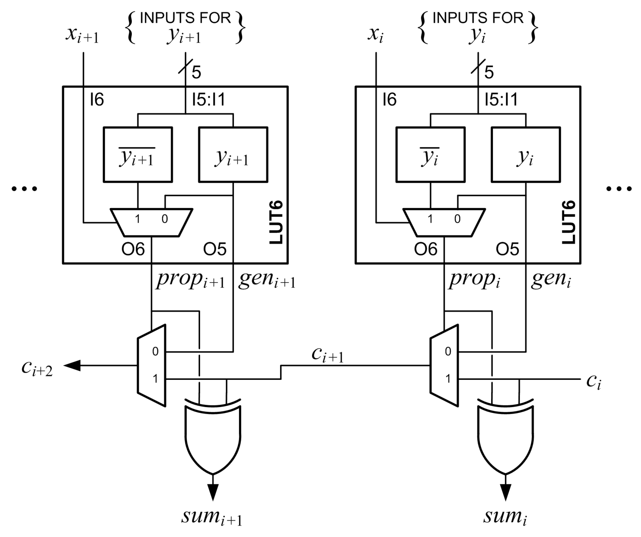
Figure 3.
Proposed ()-bit constant-coefficient multiplier (KCM), where , A is a positive constant and B is a signed variable.
Figure 3.
Proposed ()-bit constant-coefficient multiplier (KCM), where , A is a positive constant and B is a signed variable.

Figure 4.
Proposed ()-bit KCM, where , A is a negative constant and B is a signed variable. This method allows a KCM with a negative constant to be implemented using the same resources as a KCM with a positive constant at the same precision.
Figure 4.
Proposed ()-bit KCM, where , A is a negative constant and B is a signed variable. This method allows a KCM with a negative constant to be implemented using the same resources as a KCM with a positive constant at the same precision.

Figure 5.
Proposed ()-bit KCM, where , A is a negative constant and B is a signed variable. When A is positive, the pre-computed values are different but the grouping of partial products and required resources are the same.
Figure 5.
Proposed ()-bit KCM, where , A is a negative constant and B is a signed variable. When A is positive, the pre-computed values are different but the grouping of partial products and required resources are the same.
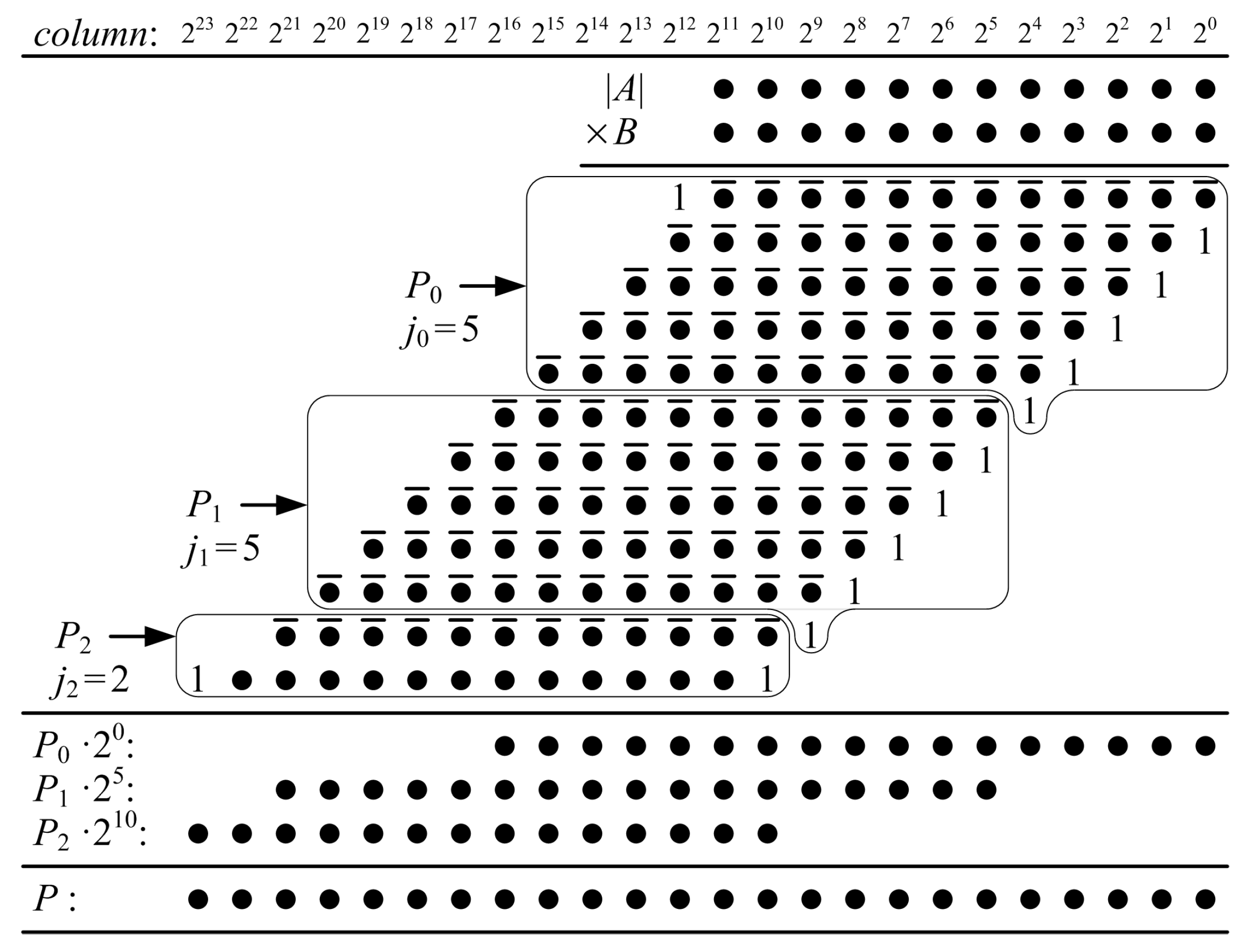
Figure 6.
Structure of proposed ()-bit KCM, where , A is a negative constant and B is a signed variable. The structure is easy to place in the logic fabric and facilitates short routing connections.
Figure 6.
Structure of proposed ()-bit KCM, where , A is a negative constant and B is a signed variable. The structure is easy to place in the logic fabric and facilitates short routing connections.

Figure 7.
Number of 6-input lookup tables (LUT6s) required for KCMs as m and n are varied. For a given value of n, the change in the number or LUTs is roughly proportianal to .
Figure 7.
Number of 6-input lookup tables (LUT6s) required for KCMs as m and n are varied. For a given value of n, the change in the number or LUTs is roughly proportianal to .

Figure 8.
Number of partial product bits computed and summed per LUT6 as m and n are varied. KCMs with are generally the most efficient, KCMs with generally are the least efficient. For a given value of n, efficiency increases as m increases and decreases as m decreases.
Figure 8.
Number of partial product bits computed and summed per LUT6 as m and n are varied. KCMs with are generally the most efficient, KCMs with generally are the least efficient. For a given value of n, efficiency increases as m increases and decreases as m decreases.

Figure 9.
Proposed ()-bit KCM with two selectable coefficients, where , is a negative constant and is a signed variable. This example does not require any additional resources compared to a ()-bit KCM with a single coefficient.
Figure 9.
Proposed ()-bit KCM with two selectable coefficients, where , is a negative constant and is a signed variable. This example does not require any additional resources compared to a ()-bit KCM with a single coefficient.
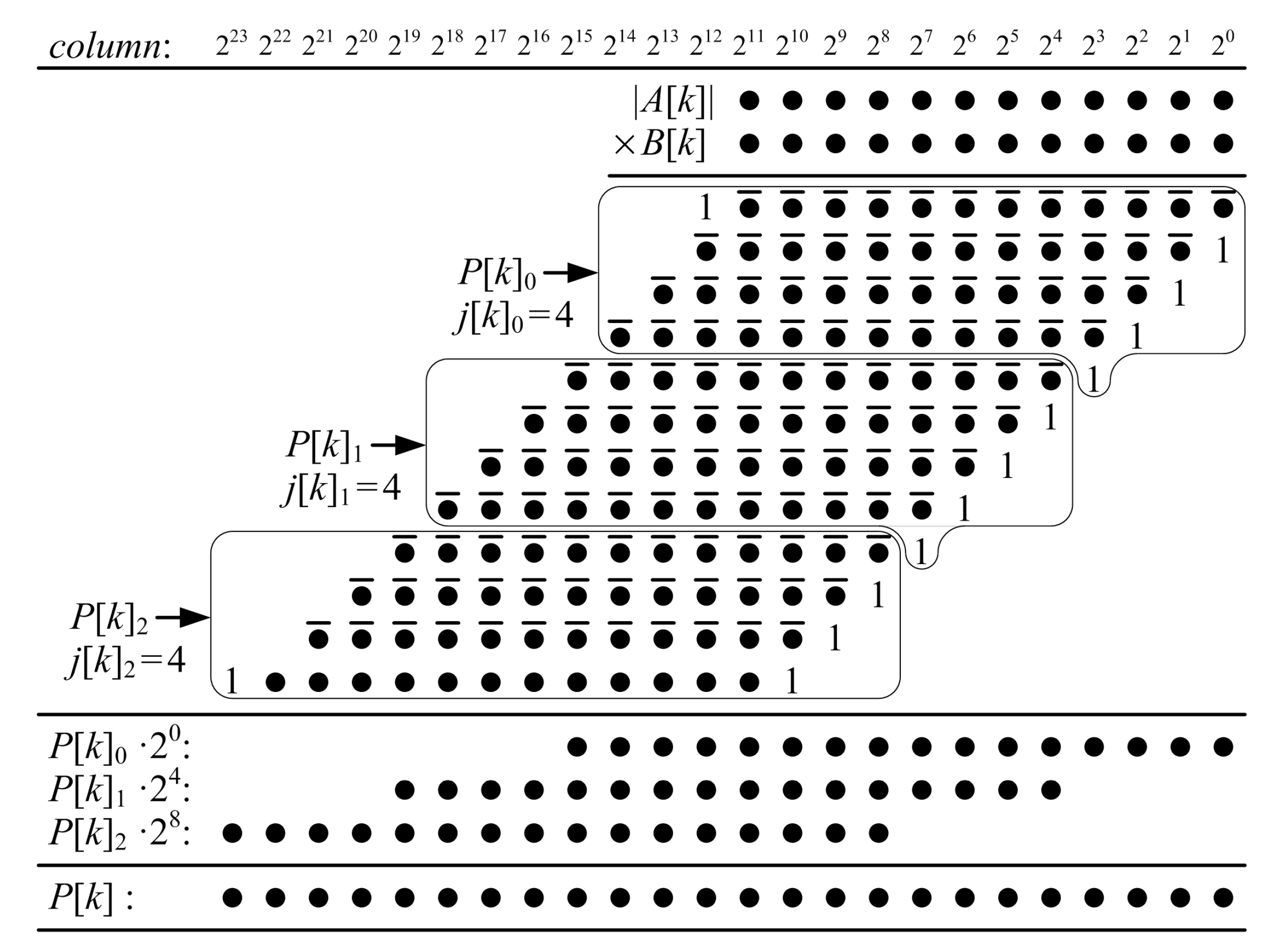
Figure 10.
Proposed ()-bit KCM with four selectable coefficients, where , is a negative constant and is a signed variable). This example requires approximately 33% more LUTs and one extra stage if pipelined compared to a ()-bit KCM with a single coefficient.
Figure 10.
Proposed ()-bit KCM with four selectable coefficients, where , is a negative constant and is a signed variable). This example requires approximately 33% more LUTs and one extra stage if pipelined compared to a ()-bit KCM with a single coefficient.

Figure 11.
Proposed ()-bit KCM with eight selectable coefficients, where , is a negative constant and is a signed variable). This example requires approximately 93% more LUTs and three extra stages if pipelined compared to a ()-bit KCM with a single coefficient.
Figure 11.
Proposed ()-bit KCM with eight selectable coefficients, where , is a negative constant and is a signed variable). This example requires approximately 93% more LUTs and three extra stages if pipelined compared to a ()-bit KCM with a single coefficient.
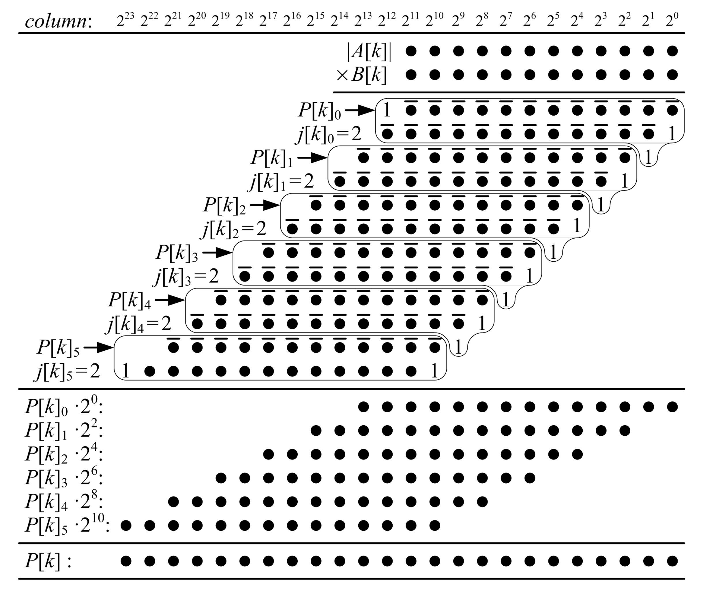
Figure 12.
LUT6s required for KCMs with one, two, four and eight coefficients, .

Figure 13.
Number of partial product bits computed and summed per LUT6 for KCMs with one, two, four and eight coefficients, .
Figure 13.
Number of partial product bits computed and summed per LUT6 for KCMs with one, two, four and eight coefficients, .
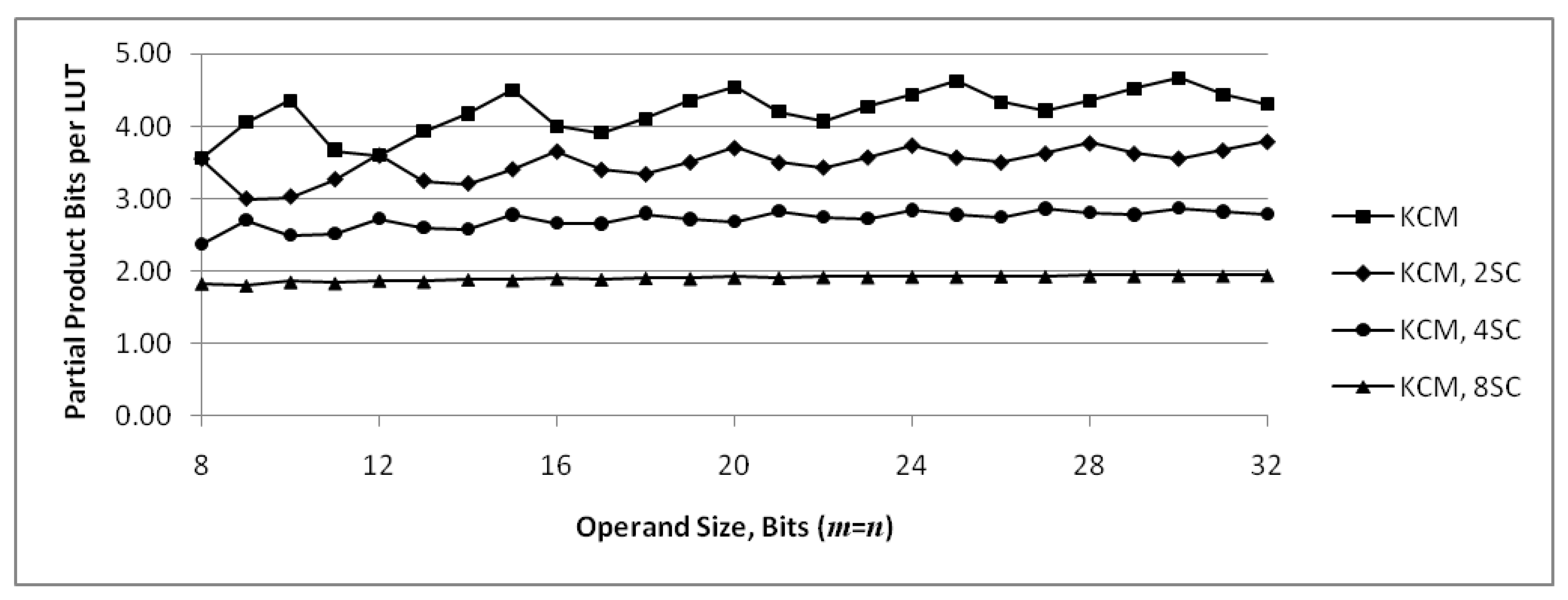
Figure 14.
LUT6s required for KCMs, . Values for proposed KCMs are computed maximums, and values for LogiCORE are from synthesized results.
Figure 14.
LUT6s required for KCMs, . Values for proposed KCMs are computed maximums, and values for LogiCORE are from synthesized results.
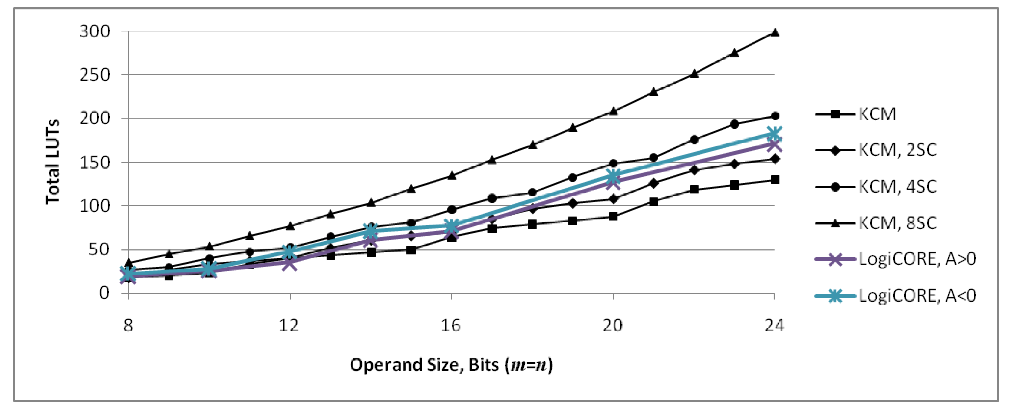
Figure 16.
Slice utilization for directed acyclic graph (DAG) fusion [11,13], pipelined adder graph (PAG) fusion [13] and proposed ()-bit KCMs with two to eight selectable coefficients. One slice contains four LUT6s and eight flip-flops (see Figure 1). DAG fusion and PAG fusion units are normalized to CoreGen as presented in Möller et al. [13], proposed units are normalized to a LogiCORE IP multiplier-based unit.
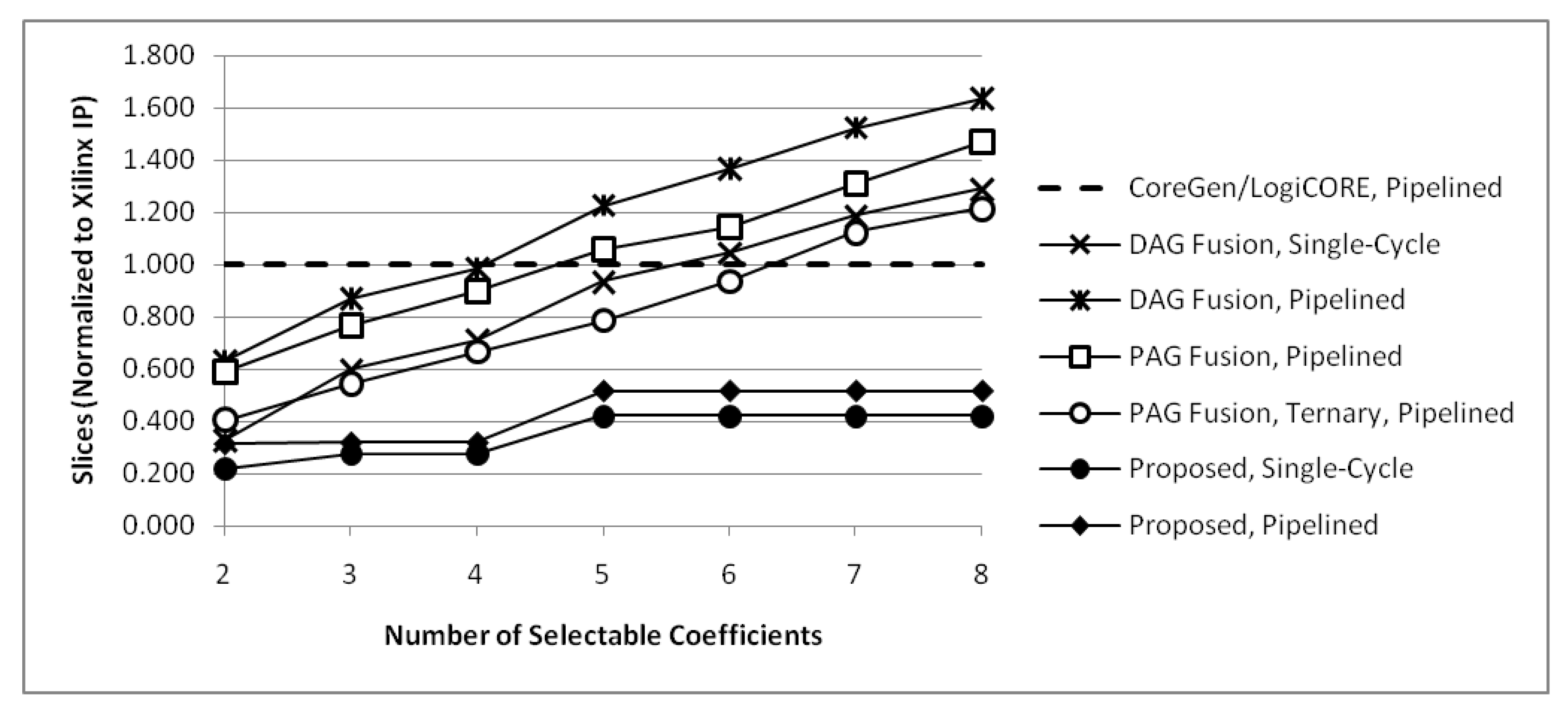
Figure 17.
Maximum operating frequency for DAG fusion [11,13], PAG fusion [13] and proposed ()-bit KCMs with two to eight selectable coefficients. DAG fusion and PAG fusion units are normalized to CoreGen as presented in Möller et al. [13], proposed units are normalized to a LogiCORE IP multiplier-based unit.


Table 1.
Comparison of one, two, four and eight-coefficient ()-bit constant-coefficient multipliers (KCMs), where . The increase in LUTs for multiple-coefficient KCMs is less than using separate KCMs with a multiplexer or a general-purpose multiplier with multiplexed constants.
Table 1.
Comparison of one, two, four and eight-coefficient ()-bit constant-coefficient multipliers (KCMs), where . The increase in LUTs for multiple-coefficient KCMs is less than using separate KCMs with a multiplexer or a general-purpose multiplier with multiplexed constants.
| One Coefficient | Two Coefficient | Four Coefficient | Eight Coefficient | ||||||||
|---|---|---|---|---|---|---|---|---|---|---|---|
| n | PPs | LUTs | PPs | LUTs | Increase | PPs | LUTs | Increase | PPs | LUTs | Increase |
| 8 | 2 | 18 | 2 | 18 | 0% | 3 | 27 | 50% | 4 | 35 | 94% |
| 10 | 2 | 23 | 3 | 33 | 43% | 3 | 40 | 74% | 5 | 54 | 135% |
| 12 | 3 | 40 | 3 | 40 | 0% | 4 | 53 | 33% | 6 | 77 | 93% |
| 14 | 3 | 47 | 4 | 61 | 30% | 5 | 76 | 62% | 7 | 104 | 121% |
| 16 | 3 | 64 | 4 | 70 | 9% | 5 | 96 | 50% | 8 | 135 | 111% |
| 18 | 4 | 79 | 5 | 97 | 23% | 6 | 116 | 47% | 9 | 170 | 115% |
| 20 | 4 | 88 | 5 | 108 | 23% | 7 | 149 | 69% | 10 | 209 | 138% |
| 22 | 5 | 119 | 6 | 141 | 18% | 7 | 176 | 48% | 11 | 252 | 112% |
| 24 | 5 | 130 | 6 | 154 | 18% | 8 | 203 | 56% | 12 | 299 | 130% |
Acronyms: partial products (PPs), lookup tables (LUTs).
Table 2.
Values of used for synthesis, , , and rounded to nearest odd.
| Magnitude of A, | Magnitude of A, | |||
|---|---|---|---|---|
| n | Integer | Binary | Integer | Binary |
| 8 | 201 | 11001001 | 151 | 10010111 |
| 10 | 805 | 1100100101 | 603 | 1001011011 |
| 12 | 3,217 | 110010010001 | 2,413 | 100101101101 |
| 14 | 12,867 | 11001001000011 | 9,651 | 10010110110011 |
| 16 | 51,471 | 1100100100001111 | 38,603 | 1001011011001011 |
| 20 | 823,549 | 11001001000011111101 | 617,663 | 10010110110010111111 |
| 24 | 13,176,795 | 110010010000111111011011 | 9,882,595 | 100101101100101111100011 |
| Magnitude of A, | Magnitude of A, | |||
| n | Integer | Binary | Integer | Binary |
| 8 | 251 | 11111011 | 175 | 10101111 |
| 10 | 1,005 | 1111101101 | 703 | 1010111111 |
| 12 | 4,021 | 111110110101 | 2,815 | 101011111111 |
| 14 | 16,085 | 11111011010101 | 11,259 | 10101111111011 |
| 16 | 64,339 | 1111111101111011 | 45,037 | 1010111111101101 |
| 20 | 1,029,437 | 11111011010100111101 | 720,605 | 10101111111011011101 |
| 24 | 16,470,993 | 111110110101001111010001 | 11,529,695 | 101011111110110111011111 |
Table 3.
Synthesis results for single-cycle ()-bit KCMs, where , and B is a signed variable. Proposed KCMs use 15% fewer LUTs on average compared to LogiCORE IP KCMs at the expense of increased delay.
Table 3.
Synthesis results for single-cycle ()-bit KCMs, where , and B is a signed variable. Proposed KCMs use 15% fewer LUTs on average compared to LogiCORE IP KCMs at the expense of increased delay.
| Type | Total | Delay | Normalized | ||||
|---|---|---|---|---|---|---|---|
| n | LUTs | (ns) | LDP | LUTs | Delay | LDP | |
| LogiCORE IP B is signed | 8 | 19 | 0.972 | 18.5 | 1.000 | 1.000 | 1.000 |
| 10 | 26 | 1.083 | 28.2 | 1.000 | 1.000 | 1.000 | |
| 12 | 35 | 1.112 | 38.9 | 1.000 | 1.000 | 1.000 | |
| 14 | 61 | 1.786 | 108.9 | 1.000 | 1.000 | 1.000 | |
| 16 | 71 | 1.869 | 132.7 | 1.000 | 1.000 | 1.000 | |
| 20 | 127 | 2.033 | 258.2 | 1.000 | 1.000 | 1.000 | |
| 24 | 171 | 2.044 | 349.5 | 1.000 | 1.000 | 1.000 | |
| Proposed KCM B is signed | 8 | 17 | 1.463 | 24.9 | 0.895 | 1.505 | 1.347 |
| 10 | 22 | 1.475 | 32.5 | 0.846 | 1.362 | 1.152 | |
| 12 | 40 | 2.308 | 92.3 | 1.143 | 2.076 | 2.372 | |
| 14 | 47 | 2.454 | 115.3 | 0.770 | 1.374 | 1.059 | |
| 16 | 63 | 2.306 | 145.3 | 0.887 | 1.234 | 1.095 | |
| 20 | 87 | 3.149 | 274.0 | 0.685 | 1.549 | 1.061 | |
| 24 | 129 | 4.025 | 519.2 | 0.754 | 1.969 | 1.486 | |
Acronyms: lookup tables (LUTs), LUT-delay product (LDP).
Table 4.
Synthesis results for single-cycle ()-bit KCMs, where , and B is a signed variable. Proposed KCMs use 26% fewer LUTs on average compared to LogiCORE IP KCMs, a significant improvement compared to KCMs with a positive constant.
Table 4.
Synthesis results for single-cycle ()-bit KCMs, where , and B is a signed variable. Proposed KCMs use 26% fewer LUTs on average compared to LogiCORE IP KCMs, a significant improvement compared to KCMs with a positive constant.
| Type | Total | Delay | Normalized | ||||
|---|---|---|---|---|---|---|---|
| n | LUTs | (ns) | LDP | LUTs | Delay | LDP | |
| LogiCORE IP B is signed | 8 | 22 | 0.958 | 21.1 | 1.000 | 1.000 | 1.000 |
| 10 | 28 | 1.117 | 31.3 | 1.000 | 1.000 | 1.000 | |
| 12 | 47 | 1.115 | 52.4 | 1.000 | 1.000 | 1.000 | |
| 14 | 71 | 1.821 | 129.3 | 1.000 | 1.000 | 1.000 | |
| 16 | 77 | 1.860 | 143.2 | 1.000 | 1.000 | 1.000 | |
| 20 | 134 | 1.980 | 265.3 | 1.000 | 1.000 | 1.000 | |
| 24 | 183 | 2.092 | 382.8 | 1.000 | 1.000 | 1.000 | |
| Proposed KCM B is signed | 8 | 17 | 1.500 | 25.5 | 0.773 | 1.566 | 1.210 |
| 10 | 22 | 1.595 | 35.1 | 0.786 | 1.428 | 1.122 | |
| 12 | 39 | 2.366 | 92.3 | 0.830 | 2.122 | 1.761 | |
| 14 | 46 | 2.405 | 110.6 | 0.648 | 1.321 | 0.856 | |
| 16 | 60 | 2.272 | 136.3 | 0.779 | 1.222 | 0.952 | |
| 20 | 87 | 3.190 | 277.5 | 0.649 | 1.611 | 1.046 | |
| 24 | 129 | 3.969 | 512.0 | 0.705 | 1.897 | 1.337 | |
Acronyms: lookup tables (LUTs), LUT-delay product (LDP).
Table 5.
Synthesis results for pipelined ()-bit KCMs, where , and B is a signed variable. Proposed KCMs use 22% fewer LUTs on average compared to LogiCORE IP KCMs and the increase in delay is less significant than it is for single-cycle units.
Table 5.
Synthesis results for pipelined ()-bit KCMs, where , and B is a signed variable. Proposed KCMs use 22% fewer LUTs on average compared to LogiCORE IP KCMs and the increase in delay is less significant than it is for single-cycle units.
| Type | Pipeline | Total | Delay | Normalized | ||||
|---|---|---|---|---|---|---|---|---|
| n | Stages | LUTs | (ns) | LDP | LUTs | Delay | LDP | |
| LogiCORE IP B is signed | 8 | 2 | 20 | 0.914 | 18.3 | 1.000 | 1.000 | 1.000 |
| 10 | 2 | 28 | 1.000 | 28.0 | 1.000 | 1.000 | 1.000 | |
| 12 | 2 | 37 | 1.066 | 39.4 | 1.000 | 1.000 | 1.000 | |
| 14 | 3 | 71 | 1.143 | 81.2 | 1.000 | 1.000 | 1.000 | |
| 16 | 3 | 84 | 1.186 | 99.6 | 1.000 | 1.000 | 1.000 | |
| 20 | 3 | 135 | 1.270 | 171.5 | 1.000 | 1.000 | 1.000 | |
| 24 | 3 | 184 | 1.334 | 245.5 | 1.000 | 1.000 | 1.000 | |
| Proposed KCM B is signed | 8 | 2 | 17 | 1.122 | 19.1 | 0.850 | 1.228 | 1.043 |
| 10 | 2 | 22 | 1.284 | 28.2 | 0.786 | 1.284 | 1.009 | |
| 12 | 3 | 39 | 1.478 | 57.6 | 1.054 | 1.386 | 1.461 | |
| 14 | 3 | 46 | 1.500 | 69.0 | 0.648 | 1.312 | 0.850 | |
| 16 | 3 | 63 | 1.538 | 96.9 | 0.750 | 1.297 | 0.973 | |
| 20 | 4 | 87 | 1.628 | 141.6 | 0.644 | 1.282 | 0.826 | |
| 24 | 5 | 138 | 1.802 | 248.7 | 0.750 | 1.351 | 1.013 | |
Acronyms: lookup tables (LUTs), LUT-delay product (LDP).
Table 6.
Synthesis results for pipelined ()-bit KCMs, where , and B is a signed variable. Proposed KCMs use 33% fewer LUTs and have a 14% lower LDP on average compared to LogiCORE IP KCMs.
Table 6.
Synthesis results for pipelined ()-bit KCMs, where , and B is a signed variable. Proposed KCMs use 33% fewer LUTs and have a 14% lower LDP on average compared to LogiCORE IP KCMs.
| Type | Pipeline | Total | Delay | Normalized | ||||
|---|---|---|---|---|---|---|---|---|
| n | Stages | LUTs | (ns) | LDP | LUTs | Delay | LDP | |
| LogiCORE IP B is signed | 8 | 2 | 24 | 0.962 | 23.1 | 1.000 | 1.000 | 1.000 |
| 10 | 2 | 34 | 0.963 | 32.7 | 1.000 | 1.000 | 1.000 | |
| 12 | 2 | 49 | 1.071 | 52.5 | 1.000 | 1.000 | 1.000 | |
| 14 | 3 | 80 | 1.174 | 93.9 | 1.000 | 1.000 | 1.000 | |
| 16 | 3 | 90 | 1.188 | 106.9 | 1.000 | 1.000 | 1.000 | |
| 20 | 3 | 146 | 1.279 | 186.7 | 1.000 | 1.000 | 1.000 | |
| 24 | 3 | 198 | 1.360 | 269.3 | 1.000 | 1.000 | 1.000 | |
| Proposed KCM B is signed | 8 | 2 | 17 | 1.184 | 20.1 | 0.708 | 1.231 | 0.872 |
| 10 | 2 | 22 | 1.227 | 27.0 | 0.647 | 1.274 | 0.824 | |
| 12 | 3 | 39 | 1.450 | 56.6 | 0.796 | 1.354 | 1.078 | |
| 14 | 3 | 46 | 1.480 | 68.1 | 0.575 | 1.261 | 0.725 | |
| 16 | 3 | 60 | 1.505 | 90.3 | 0.667 | 1.267 | 0.845 | |
| 20 | 4 | 87 | 1.615 | 140.5 | 0.596 | 1.263 | 0.752 | |
| 24 | 5 | 138 | 1.739 | 240.0 | 0.697 | 1.279 | 0.891 | |
Acronyms: lookup tables (LUTs), LUT-delay product (LDP).
Table 7.
Synthesis results for single-cycle ()-bit KCMs with two selectable coefficients, where , and both are signed variables. Proposed units use 62% fewer LUTs on average compared to LogiCORE IP KCM-based units.
Table 7.
Synthesis results for single-cycle ()-bit KCMs with two selectable coefficients, where , and both are signed variables. Proposed units use 62% fewer LUTs on average compared to LogiCORE IP KCM-based units.
| Type | Total | Delay | Normalized | ||||
|---|---|---|---|---|---|---|---|
| n | LUTs | (ns) | LDP | LUTs | Delay | LDP | |
| LogiCORE IP Lookup + Multiplier B[k] is signed | 8 | 67 | 2.861 | 191.7 | 1.136 | 2.199 | 2.497 |
| 10 | 104 | 3.676 | 382.3 | 1.368 | 2.749 | 3.762 | |
| 12 | 151 | 3.935 | 594.2 | 1.438 | 2.752 | 3.957 | |
| 14 | 205 | 4.088 | 838.0 | 1.289 | 1.829 | 2.358 | |
| 16 | 270 | 3.980 | 1074.6 | 1.508 | 1.446 | 2.181 | |
| 20 | 420 | 5.013 | 2105.5 | 1.405 | 1.843 | 2.589 | |
| 24 | 603 | 4.982 | 3004.1 | 1.508 | 1.727 | 2.603 | |
| LogiCORE IP KCMs + MUX B[k] is signed | 8 | 59 | 1.301 | 76.8 | 1.000 | 1.000 | 1.000 |
| 10 | 76 | 1.337 | 101.6 | 1.000 | 1.000 | 1.000 | |
| 12 | 105 | 1.430 | 150.2 | 1.000 | 1.000 | 1.000 | |
| 14 | 159 | 2.235 | 355.4 | 1.000 | 1.000 | 1.000 | |
| 16 | 179 | 2.753 | 492.8 | 1.000 | 1.000 | 1.000 | |
| 20 | 299 | 2.720 | 813.3 | 1.000 | 1.000 | 1.000 | |
| 24 | 400 | 2.885 | 1154.0 | 1.000 | 1.000 | 1.000 | |
| Proposed KCM B[k] is signed | 8 | 18 | 1.468 | 26.4 | 0.305 | 1.128 | 0.344 |
| 10 | 33 | 2.211 | 73.0 | 0.434 | 1.654 | 0.718 | |
| 12 | 40 | 2.305 | 92.2 | 0.381 | 1.612 | 0.614 | |
| 14 | 61 | 3.146 | 191.9 | 0.384 | 1.408 | 0.540 | |
| 16 | 70 | 3.210 | 224.7 | 0.391 | 1.166 | 0.456 | |
| 20 | 108 | 4.012 | 433.3 | 0.361 | 1.475 | 0.533 | |
| 24 | 154 | 5.009 | 771.4 | 0.385 | 1.736 | 0.668 | |
Acronyms: lookup tables (LUTs), LUT-delay product (LDP).
Table 8.
Synthesis results for pipelined ()-bit KCMs with two selectable coefficients, where , and both are signed variables. Proposed units use 64% fewer LUTs and have a 58% lower LDP on average compared to LogiCORE IP KCM-based units.
Table 8.
Synthesis results for pipelined ()-bit KCMs with two selectable coefficients, where , and both are signed variables. Proposed units use 64% fewer LUTs and have a 58% lower LDP on average compared to LogiCORE IP KCM-based units.
| Type | Pipeline | Total | Delay | Normalized | ||||
|---|---|---|---|---|---|---|---|---|
| n | Stages | LUTs | (ns) | LDP | LUTs | Delay | LDP | |
| LogiCORE IP Lookup + Multiplier is signed | 8 | 4 | 67 | 1.510 | 101.2 | 1.117 | 1.593 | 1.779 |
| 10 | 5 | 106 | 1.476 | 156.5 | 1.268 | 1.440 | 1.861 | |
| 12 | 5 | 153 | 1.604 | 245.4 | 1.385 | 1.489 | 2.091 | |
| 14 | 5 | 207 | 1.590 | 329.1 | 1.152 | 1.355 | 1.576 | |
| 16 | 5 | 272 | 1.825 | 496.4 | 1.364 | 1.451 | 1.916 | |
| 20 | 6 | 426 | 1.917 | 816.6 | 1.350 | 1.425 | 1.903 | |
| 24 | 6 | 609 | 1.932 | 1176.6 | 1.436 | 1.442 | 2.052 | |
| LogiCORE IP KCMs + MUX is signed | 8 | 3 | 60 | 0.948 | 56.9 | 1.000 | 1.000 | 1.000 |
| 10 | 3 | 82 | 1.025 | 84.1 | 1.000 | 1.000 | 1.000 | |
| 12 | 3 | 109 | 1.077 | 117.4 | 1.000 | 1.000 | 1.000 | |
| 14 | 4 | 178 | 1.173 | 208.8 | 1.000 | 1.000 | 1.000 | |
| 16 | 4 | 206 | 1.258 | 259.1 | 1.000 | 1.000 | 1.000 | |
| 20 | 4 | 319 | 1.345 | 429.1 | 1.000 | 1.000 | 1.000 | |
| 24 | 4 | 428 | 1.340 | 573.5 | 1.000 | 1.000 | 1.000 | |
| Proposed KCM is signed | 8 | 2 | 18 | 1.211 | 21.8 | 0.300 | 1.277 | 0.383 |
| 10 | 3 | 33 | 1.404 | 46.3 | 0.402 | 1.370 | 0.551 | |
| 12 | 3 | 40 | 1.256 | 50.2 | 0.367 | 1.166 | 0.428 | |
| 14 | 4 | 61 | 1.429 | 87.2 | 0.343 | 1.218 | 0.417 | |
| 16 | 4 | 70 | 1.407 | 98.5 | 0.340 | 1.118 | 0.380 | |
| 20 | 5 | 116 | 1.379 | 160.0 | 0.364 | 1.025 | 0.373 | |
| 24 | 6 | 170 | 1.451 | 246.7 | 0.397 | 1.083 | 0.430 | |
Acronyms: lookup tables (LUTs), LUT-delay product (LDP).
Table 9.
Synthesis results for single-cycle ()-bit KCMs with four selectable coefficients where , or and all are signed variables. Proposed units use 64% fewer LUTs on average compared to LogiCORE IP multiplier-based units and 73% fewer LUTs on average compared to LogiCORE IP KCM-based units.
Table 9.
Synthesis results for single-cycle ()-bit KCMs with four selectable coefficients where , or and all are signed variables. Proposed units use 64% fewer LUTs on average compared to LogiCORE IP multiplier-based units and 73% fewer LUTs on average compared to LogiCORE IP KCM-based units.
| Type | Total | Delay | Normalized | ||||
|---|---|---|---|---|---|---|---|
| n | LUTs | (ns) | LDP | LUTs | Delay | LDP | |
| LogiCORE IP | 8 | 67 | 2.903 | 194.5 | 1.000 | 1.000 | 1.000 |
| Lookup + Multiplier | 10 | 106 | 3.740 | 396.4 | 1.000 | 1.000 | 1.000 |
| 12 | 153 | 3.922 | 600.1 | 1.000 | 1.000 | 1.000 | |
| 14 | 207 | 3.811 | 788.9 | 1.000 | 1.000 | 1.000 | |
| 16 | 272 | 4.068 | 1106.5 | 1.000 | 1.000 | 1.000 | |
| 20 | 422 | 4.885 | 2061.5 | 1.000 | 1.000 | 1.000 | |
| is signed | 24 | 605 | 5.128 | 3102.4 | 1.000 | 1.000 | 1.000 |
| LogiCORE IP | 8 | 97 | 1.500 | 145.5 | 1.448 | 0.517 | 0.748 |
| KCMs + MUX | 10 | 127 | 1.528 | 194.1 | 1.198 | 0.409 | 0.489 |
| 12 | 191 | 1.591 | 303.9 | 1.248 | 0.406 | 0.506 | |
| 14 | 291 | 2.633 | 766.2 | 1.406 | 0.691 | 0.971 | |
| 16 | 331 | 3.102 | 1026.8 | 1.217 | 0.763 | 0.928 | |
| 20 | 554 | 2.872 | 1591.1 | 1.313 | 0.588 | 0.772 | |
| is signed | 24 | 774 | 3.019 | 2336.7 | 1.279 | 0.589 | 0.753 |
| Proposed KCM | 8 | 26 | 2.190 | 56.9 | 0.388 | 0.754 | 0.293 |
| 10 | 39 | 1.894 | 73.9 | 0.368 | 0.506 | 0.186 | |
| 12 | 52 | 3.178 | 165.3 | 0.340 | 0.810 | 0.275 | |
| 14 | 75 | 3.855 | 289.1 | 0.362 | 1.012 | 0.367 | |
| 16 | 95 | 3.604 | 342.4 | 0.349 | 0.886 | 0.309 | |
| is signed | 20 | 148 | 5.464 | 808.7 | 0.351 | 1.119 | 0.392 |
| 24 | 202 | 6.453 | 1303.5 | 0.334 | 1.258 | 0.420 | |
Acronyms: lookup tables (LUTs), LUT-delay product (LDP).
Table 10.
Synthesis results for pipelined ()-bit KCMs with four selectable coefficients where , or and all are signed variables. Proposed units use 63% fewer LUTs on average compared to LogiCORE IP multiplier-based units and 74% fewer LUTs on average compared to LogiCORE IP KCM-based units.
Table 10.
Synthesis results for pipelined ()-bit KCMs with four selectable coefficients where , or and all are signed variables. Proposed units use 63% fewer LUTs on average compared to LogiCORE IP multiplier-based units and 74% fewer LUTs on average compared to LogiCORE IP KCM-based units.
| Type | Pipeline | Total | Delay | Normalized | ||||
|---|---|---|---|---|---|---|---|---|
| n | Stages | LUTs | (ns) | LDP | LUTs | Delay | LDP | |
| LogiCORE IP | 8 | 4 | 69 | 1.635 | 112.8 | 1.000 | 1.000 | 1.000 |
| Lookup + Multiplier | 10 | 5 | 108 | 1.466 | 158.3 | 1.000 | 1.000 | 1.000 |
| 12 | 5 | 155 | 1.671 | 259.0 | 1.000 | 1.000 | 1.000 | |
| 14 | 5 | 209 | 1.640 | 342.8 | 1.000 | 1.000 | 1.000 | |
| 16 | 5 | 274 | 1.731 | 474.3 | 1.000 | 1.000 | 1.000 | |
| 20 | 6 | 428 | 1.817 | 777.7 | 1.000 | 1.000 | 1.000 | |
| is signed | 24 | 6 | 611 | 1.820 | 1112.0 | 1.000 | 1.000 | 1.000 |
| LogiCORE IP | 8 | 3 | 103 | 1.030 | 106.1 | 1.493 | 0.630 | 0.940 |
| KCMs + MUX | 10 | 3 | 145 | 1.066 | 154.6 | 1.343 | 0.727 | 0.976 |
| 12 | 3 | 200 | 1.137 | 227.4 | 1.290 | 0.680 | 0.878 | |
| 14 | 4 | 327 | 1.624 | 531.0 | 1.565 | 0.990 | 1.549 | |
| 16 | 4 | 385 | 1.403 | 540.2 | 1.405 | 0.811 | 1.139 | |
| 20 | 4 | 593 | 1.515 | 898.4 | 1.386 | 0.834 | 1.155 | |
| is signed | 24 | 4 | 823 | 1.532 | 1260.8 | 1.347 | 0.842 | 1.134 |
| Proposed KCM | 8 | 3 | 26 | 1.365 | 35.5 | 0.377 | 0.835 | 0.315 |
| 10 | 3 | 39 | 1.482 | 57.8 | 0.361 | 1.011 | 0.365 | |
| 12 | 4 | 52 | 1.404 | 73.0 | 0.335 | 0.840 | 0.282 | |
| 14 | 5 | 80 | 1.561 | 124.9 | 0.383 | 0.952 | 0.364 | |
| 16 | 5 | 102 | 1.520 | 155.0 | 0.372 | 0.878 | 0.327 | |
| is signed | 20 | 7 | 165 | 1.628 | 268.6 | 0.386 | 0.896 | 0.345 |
| 24 | 8 | 226 | 1.712 | 386.9 | 0.370 | 0.941 | 0.348 | |
Acronyms: lookup tables (LUTs), LUT-delay product (LDP).
Table 11.
Synthesis results for single-cycle ()-bit KCMs with eight selectable coefficients where , , , or and all are signed variables. Proposed units use 51% fewer LUTs on average compared to LogiCORE IP multiplier-based units.
Table 11.
Synthesis results for single-cycle ()-bit KCMs with eight selectable coefficients where , , , or and all are signed variables. Proposed units use 51% fewer LUTs on average compared to LogiCORE IP multiplier-based units.
| Type | Total | Delay | Normalized | ||||
|---|---|---|---|---|---|---|---|
| n | LUTs | (ns) | LDP | LUTs | Delay | LDP | |
| LogiCORE IP | 8 | 73 | 2.830 | 206.6 | 1.000 | 1.000 | 1.000 |
| Lookup + Multiplier | 10 | 110 | 3.838 | 422.2 | 1.000 | 1.000 | 1.000 |
| 12 | 157 | 3.892 | 611.0 | 1.000 | 1.000 | 1.000 | |
| 14 | 212 | 3.892 | 825.1 | 1.000 | 1.000 | 1.000 | |
| 16 | 278 | 4.188 | 1164.3 | 1.000 | 1.000 | 1.000 | |
| 20 | 428 | 4.968 | 2126.3 | 1.000 | 1.000 | 1.000 | |
| is signed | 24 | 611 | 5.113 | 3124.0 | 1.000 | 1.000 | 1.000 |
| Proposed KCM | 8 | 35 | 3.018 | 105.6 | 0.479 | 1.066 | 0.511 |
| 10 | 54 | 3.642 | 196.7 | 0.491 | 0.949 | 0.466 | |
| 12 | 77 | 4.428 | 341.0 | 0.490 | 1.138 | 0.558 | |
| 14 | 104 | 5.209 | 541.7 | 0.491 | 1.338 | 0.657 | |
| 16 | 135 | 6.014 | 811.9 | 0.486 | 1.436 | 0.697 | |
| is signed | 20 | 209 | 7.749 | 1619.5 | 0.488 | 1.560 | 0.762 |
| 24 | 299 | 9.067 | 2711.0 | 0.489 | 1.773 | 0.868 | |
Acronyms: lookup tables (LUTs), LUT-delay product (LDP).
Table 12.
Synthesis results for pipelined ()-bit KCMs with eight selectable coefficients where , , , or and all are signed variables. Proposed units use 47% fewer LUTs and have 15% less delay on average compared to LogiCORE IP multiplier-based units.
Table 12.
Synthesis results for pipelined ()-bit KCMs with eight selectable coefficients where , , , or and all are signed variables. Proposed units use 47% fewer LUTs and have 15% less delay on average compared to LogiCORE IP multiplier-based units.
| Type | Pipeline | Total | Delay | Normalized | ||||
|---|---|---|---|---|---|---|---|---|
| n | Stages | LUTs | (ns) | LDP | LUTs | Delay | LDP | |
| LogiCORE IP | 8 | 4 | 73 | 1.626 | 118.7 | 1.000 | 1.000 | 1.000 |
| Lookup + Multiplier | 10 | 5 | 112 | 1.460 | 163.5 | 1.000 | 1.000 | 1.000 |
| 12 | 5 | 159 | 1.690 | 268.7 | 1.000 | 1.000 | 1.000 | |
| 14 | 5 | 214 | 1.648 | 352.7 | 1.000 | 1.000 | 1.000 | |
| 16 | 5 | 280 | 1.721 | 481.9 | 1.000 | 1.000 | 1.000 | |
| 20 | 6 | 434 | 1.894 | 822.0 | 1.000 | 1.000 | 1.000 | |
| is signed | 24 | 6 | 617 | 1.988 | 1226.6 | 1.000 | 1.000 | 1.000 |
| Proposed KCM | 8 | 4 | 35 | 1.404 | 49.1 | 0.479 | 0.863 | 0.414 |
| 10 | 5 | 58 | 1.234 | 71.6 | 0.518 | 0.845 | 0.438 | |
| 12 | 6 | 85 | 1.433 | 121.8 | 0.535 | 0.848 | 0.453 | |
| 14 | 7 | 116 | 1.364 | 158.2 | 0.542 | 0.828 | 0.449 | |
| 16 | 8 | 151 | 1.549 | 233.9 | 0.539 | 0.900 | 0.485 | |
| is signed | 20 | 10 | 233 | 1.583 | 368.8 | 0.537 | 0.836 | 0.449 |
| 24 | 12 | 331 | 1.669 | 552.4 | 0.536 | 0.840 | 0.450 | |
Acronyms: lookup tables (LUTs), LUT-delay product (LDP).
Table 13.
Slice utilization for directed acyclic graph (DAG) fusion [11,13], pipelined adder graph (PAG) fusion [13] and proposed ()-bit KCMs with two to eight selectable coefficients. DAG fusion and PAG fusion units are normalized to CoreGen as presented in Möller et al. [13], proposed units are normalized to a LogiCORE IP multiplier-based unit.
| Type | Number of Selectable Coefficients | |||||||
|---|---|---|---|---|---|---|---|---|
| 2 | 3 | 4 | 5 | 6 | 7 | 8 | ||
| CoreGen, | Slices | 107 | 107 | 107 | 107 | 107 | 107 | 107 |
| pipelined [13] | Normalized | 1.000 | 1.000 | 1.000 | 1.000 | 1.000 | 1.000 | 1.000 |
| DAG Fusion, | Slices | 35 | 64 | 76 | 100 | 112 | 127 | 138 |
| single-cycle [11,13] | Normalized | 0.327 | 0.598 | 0.710 | 0.935 | 1.047 | 1.187 | 1.290 |
| DAG Fusion, | Slices | 67 | 93 | 105 | 131 | 146 | 163 | 175 |
| pipelined [11,13] | Normalized | 0.626 | 0.869 | 0.981 | 1.224 | 1.364 | 1.523 | 1.636 |
| PAG Fusion, | Slices | 63 | 82 | 96 | 113 | 122 | 140 | 157 |
| pipelined [13] | Normalized | 0.589 | 0.766 | 0.897 | 1.056 | 1.140 | 1.308 | 1.467 |
| PAG Fusion Ternary, | Slices | 43 | 58 | 71 | 84 | 100 | 120 | 130 |
| pipelined [13] | Normalized | 0.402 | 0.542 | 0.664 | 0.785 | 0.935 | 1.121 | 1.215 |
| LogiCORE IP, | Slices | 96 | 101 | 95 | ||||
| pipelined | Normalized | 1.000 | 1.000 | 1.000 | ||||
| Proposed, | Slices | 21 | 28 | 40 | ||||
| single-cycle | Normalized | 0.219 | 0.277 | 0.421 | ||||
| Proposed, | Slices | 30 | 32 | 49 | ||||
| pipelined | Normalized | 0.313 | 0.317 | 0.516 | ||||
One slice contains four LUT6s and eight flip-flops (see Figure 1).
Table 14.
Maximum operating frequency for DAG fusion [11,13], PAG fusion [13] and proposed ()-bit KCMs with two to eight selectable coefficients. DAG fusion and PAG fusion units are normalized to CoreGen as presented in Möller et al. [13], proposed units are normalized to a LogiCORE IP multiplier-based unit.
| Type | Number of Selectable Coefficients | |||||||
|---|---|---|---|---|---|---|---|---|
| 2 | 3 | 4 | 5 | 6 | 7 | 8 | ||
| CoreGen, | Freq (MHz) | 443 | 443 | 443 | 443 | 443 | 443 | 443 |
| pipelined [13] | Normalized | 1.000 | 1.000 | 1.000 | 1.000 | 1.000 | 1.000 | 1.000 |
| DAG Fusion, | Freq (MHz) | 206 | 177 | 160 | 135 | 126 | 116 | 109 |
| single-cycle [11,13] | Normalized | 0.465 | 0.399 | 0.362 | 0.304 | 0.284 | 0.261 | 0.247 |
| DAG Fusion, | Freq (MHz) | 474 | 478 | 475 | 462 | 450 | 450 | 454 |
| pipelined [11,13] | Normalized | 1.072 | 1.080 | 1.074 | 1.043 | 1.018 | 1.018 | 1.026 |
| PAG Fusion, | Freq (MHz) | 442 | 417 | 437 | 451 | 460 | 453 | 460 |
| pipelined [13] | Normalized | 0.998 | 0.942 | 0.987 | 1.019 | 1.038 | 1.024 | 1.040 |
| PAG Fusion Ternary, | Freq (MHz) | 346 | 324 | 322 | 315 | 312 | 306 | 304 |
| pipelined [13] | Normalized | 0.782 | 0.732 | 0.728 | 0.712 | 0.705 | 0.692 | 0.686 |
| LogiCORE IP, | Freq (MHz) | 548 | 577 | 581 | ||||
| pipelined | Normalized | 1.000 | 1.000 | 1.000 | ||||
| Proposed, | Freq (MHz) | 312 | 277 | 166 | ||||
| single-cycle | Normalized | 0.569 | 0.480 | 0.280 | ||||
| Proposed, | Freq (MHz) | 711 | 658 | 646 | ||||
| pipelined | Normalized | 1.297 | 1.138 | 1.111 | ||||
Table 15.
Comparison of normalized slice utilization for PAG fusion [13] and proposed ()-bit KCMs with two to eight selectable coefficients. Proposed units use 57% fewer slices on average compared to PAG fusion units with two-operand adders and 44% fewer slices on average compared to PAG fusion units with ternary adders.
| Type | Number of Selectable Coefficients | |||||||
|---|---|---|---|---|---|---|---|---|
| 2 | 3 | 4 | 5 | 6 | 7 | 8 | ||
| (a) PAG Fusion, | Normalized Slices | 0.589 | 0.766 | 0.897 | 1.056 | 1.140 | 1.308 | 1.467 |
| pipelined [13] | Normalized to (a) | 1.000 | 1.000 | 1.000 | 1.000 | 1.000 | 1.000 | 1.000 |
| Normalized to (b) | 1.465 | 1.414 | 1.352 | 1.345 | 1.220 | 1.167 | 1.208 | |
| (b) PAG Fusion Ternary, | Normalized Slices | 0.402 | 0.542 | 0.664 | 0.785 | 0.935 | 1.121 | 1.215 |
| pipelined [13] | Normalized to (a) | 0.683 | 0.707 | 0.740 | 0.743 | 0.820 | 0.857 | 0.828 |
| Normalized to (b) | 1.000 | 1.000 | 1.000 | 1.000 | 1.000 | 1.000 | 1.000 | |
| Proposed, | Normalized Slices | 0.313 | 0.317 | 0.317 | 0.516 | 0.516 | 0.516 | 0.516 |
| pipelined | Normalized to (a) | 0.531 | 0.413 | 0.353 | 0.488 | 0.452 | 0.394 | 0.352 |
| Normalized to (b) | 0.778 | 0.584 | 0.477 | 0.657 | 0.552 | 0.460 | 0.425 | |
Table 16.
Comparison of normalized maximum operating frequency for PAG fusion [13] and proposed ()-bit KCMs with two to eight selectable coefficients. Proposed units can operate 14% faster on average compared to PAG fusion units with two-operand adders and 40% faster on average compared to PAG fusion units with ternary adders.
| Type | Number of Selectable Coefficients | |||||||
|---|---|---|---|---|---|---|---|---|
| 2 | 3 | 4 | 5 | 6 | 7 | 8 | ||
| (a) PAG Fusion, | Normalized Freq (MHz) | 0.998 | 0.942 | 0.987 | 1.019 | 1.038 | 1.024 | 1.040 |
| pipelined [13] | Normalized to (a) | 1.000 | 1.000 | 1.000 | 1.000 | 1.000 | 1.000 | 1.000 |
| Normalized to (b) | 1.277 | 1.287 | 1.357 | 1.432 | 1.473 | 1.479 | 1.516 | |
| (b) PAG Fusion Ternary, | Normalized Freq (MHz) | 0.782 | 0.732 | 0.728 | 0.712 | 0.705 | 0.692 | 0.686 |
| pipelined [13] | Normalized to (a) | 0.783 | 0.777 | 0.737 | 0.698 | 0.679 | 0.676 | 0.659 |
| Normalized to (b) | 1.000 | 1.000 | 1.000 | 1.000 | 1.000 | 1.000 | 1.000 | |
| Proposed, | Normalized Freq (MHz) | 1.297 | 1.138 | 1.138 | 1.111 | 1.111 | 1.111 | 1.111 |
| pipelined | Normalized to (a) | 1.299 | 1.209 | 1.154 | 1.090 | 1.070 | 1.085 | 1.068 |
| Normalized to (b) | 1.277 | 1.287 | 1.357 | 1.432 | 1.473 | 1.479 | 1.516 | |
© 2017 by the author. Licensee MDPI, Basel, Switzerland. This article is an open access article distributed under the terms and conditions of the Creative Commons Attribution (CC BY) license (http://creativecommons.org/licenses/by/4.0/).
Share and Cite
MDPI and ACS Style
Walters, E.G., III. Reduced-Area Constant-Coefficient and Multiple-Constant Multipliers for Xilinx FPGAs with 6-Input LUTs. Electronics 2017, 6, 101. https://doi.org/10.3390/electronics6040101
AMA Style
Walters EG III. Reduced-Area Constant-Coefficient and Multiple-Constant Multipliers for Xilinx FPGAs with 6-Input LUTs. Electronics. 2017; 6(4):101. https://doi.org/10.3390/electronics6040101
Chicago/Turabian StyleWalters, E. George, III. 2017. "Reduced-Area Constant-Coefficient and Multiple-Constant Multipliers for Xilinx FPGAs with 6-Input LUTs" Electronics 6, no. 4: 101. https://doi.org/10.3390/electronics6040101
Note that from the first issue of 2016, this journal uses article numbers instead of page numbers. See further details here.