
Domain Specific and Model Based Systems Engineering in the Smart Grid as Prerequesite for Security by Design

Abstract
:
1. Introduction
2. Related Work
2.1. IEC 62559-2 Use Case Template
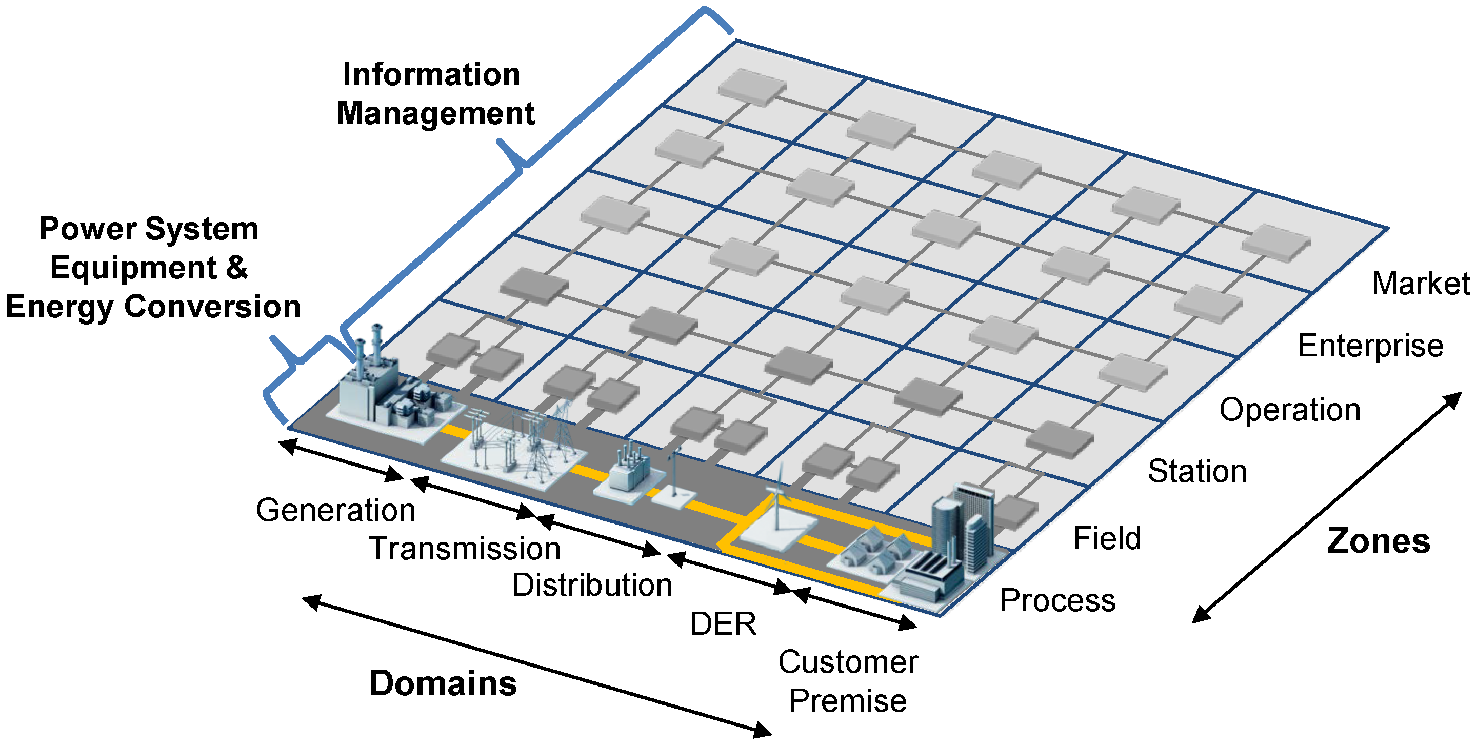
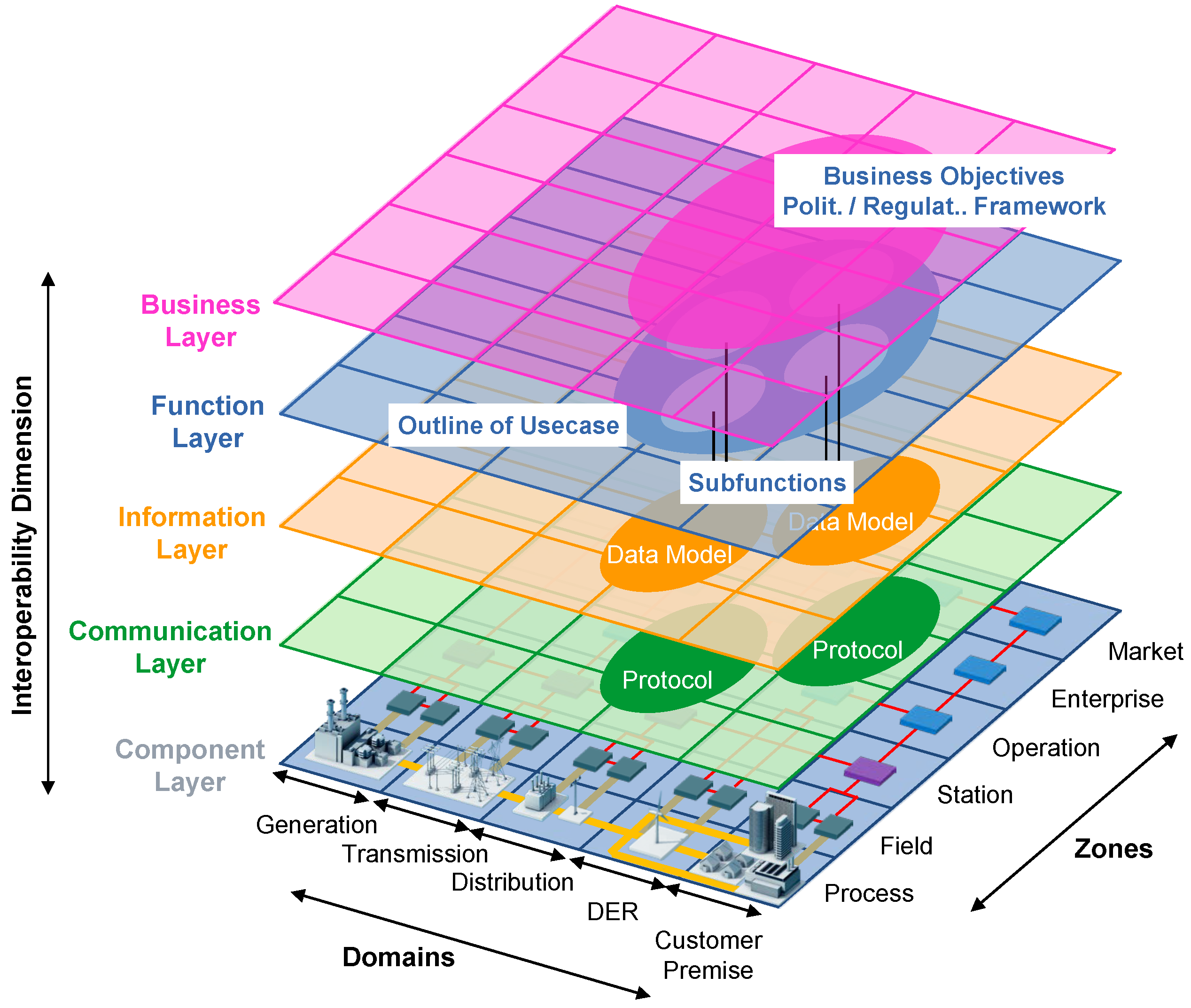
2.2. Smart Grid Architecture Model (SGAM)
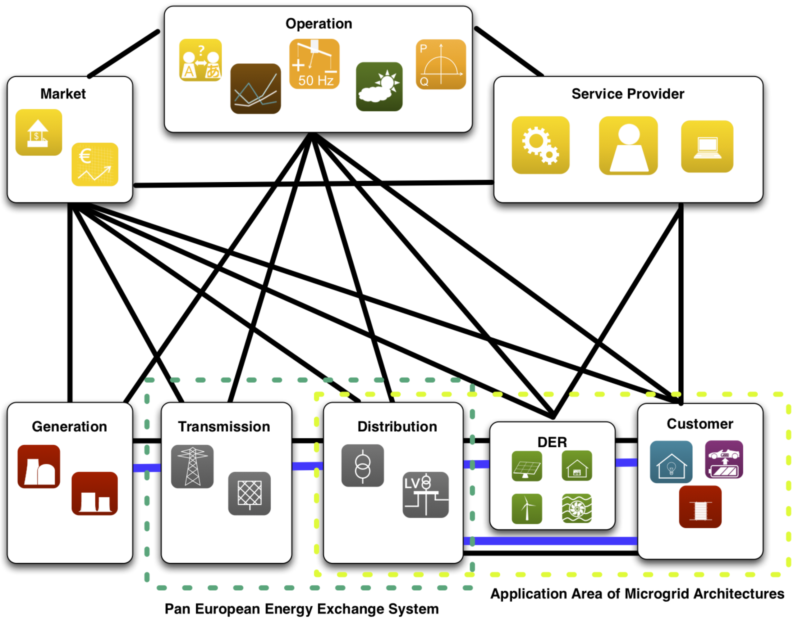
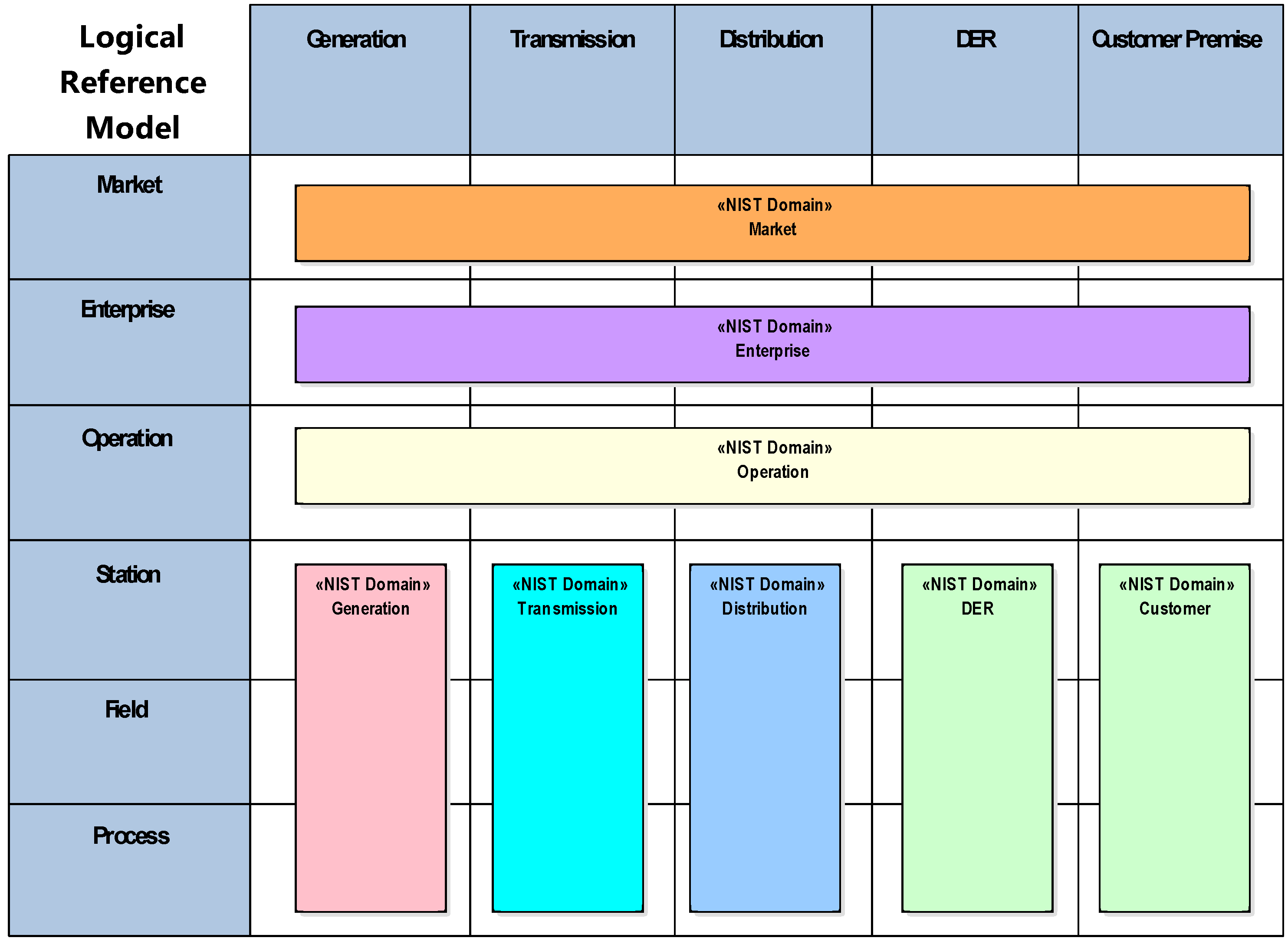
- Bulk Generation: Representing generation of electrical energy in bulk quantities, such as by fossil, nuclear and hydro power plants, off-shore wind farms, large scale solar power plant (i.e., PV, CSP)—typically connected to the transmission system;
- Transmission: Representing the infrastructure and organization which transports electricity over long distances;
- Distribution: Representing the infrastructure and organization which distributes electricity to customers;
- DER: Representing distributed electrical resources directly connected to the public distribution grid, applying small-scale power generation technologies (typically in the range of 3 kW to 10,000 kW). These distributed electrical resources may be directly controlled by DSO;
- Customer Premises: Hosting both-end users of electricity, also producers of electricity. The premises include industrial, commercial and home facilities (e.g., chemical plants, airports, harbors, shopping centers, homes). Also generation in form of e.g., photovoltaic generation, electric vehicles storage, batteries, micro turbines, etc., are hosted.
- Market: Reflecting the market operations possible along the energy conversion chain, e.g., energy trading, mass market, retail market, etc.
- Enterprise: Includes commercial and organizational processes, services and infrastructures for enterprises (utilities, service providers, energy traders, etc.), e.g., asset management, logistics, work force management, staff training, customer relation management, billing and procurement, etc.
- Operation: Hosting power system control operation in the respective domain, e.g., distribution management systems (DMS), energy management systems (EMS) in generation and transmission systems, microgrid management systems, virtual power plant management systems (aggregating several DER), electric vehicle (EV) fleet charging management systems.
- Station: Representing the areal aggregation level for field level, e.g., for data concentration, functional aggregation, substation automation, local SCADA systems, plant supervision, etc.,
- Field: Including equipment to protect, control and monitor the process of the power system, e.g., protection relays, bay controller, any kind of intelligent electronic devices which acquire and use process data from the power system.
- Process: Including the physical, chemical or spatial transformations of energy (electricity, solar, heat, water, wind, etc.) and the physical equipment directly involved. (e.g., generators, transformers, circuit breakers, overhead lines, cables, electrical loads any kind of sensors and actuators which are part or directly connected to the process, etc.).
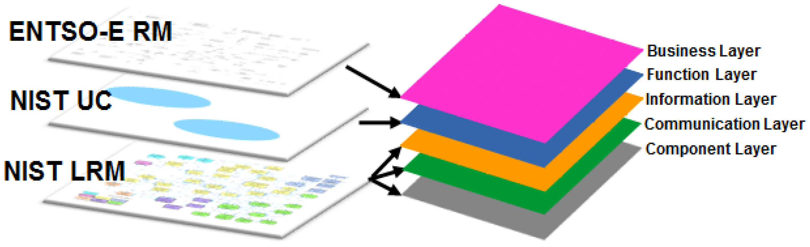
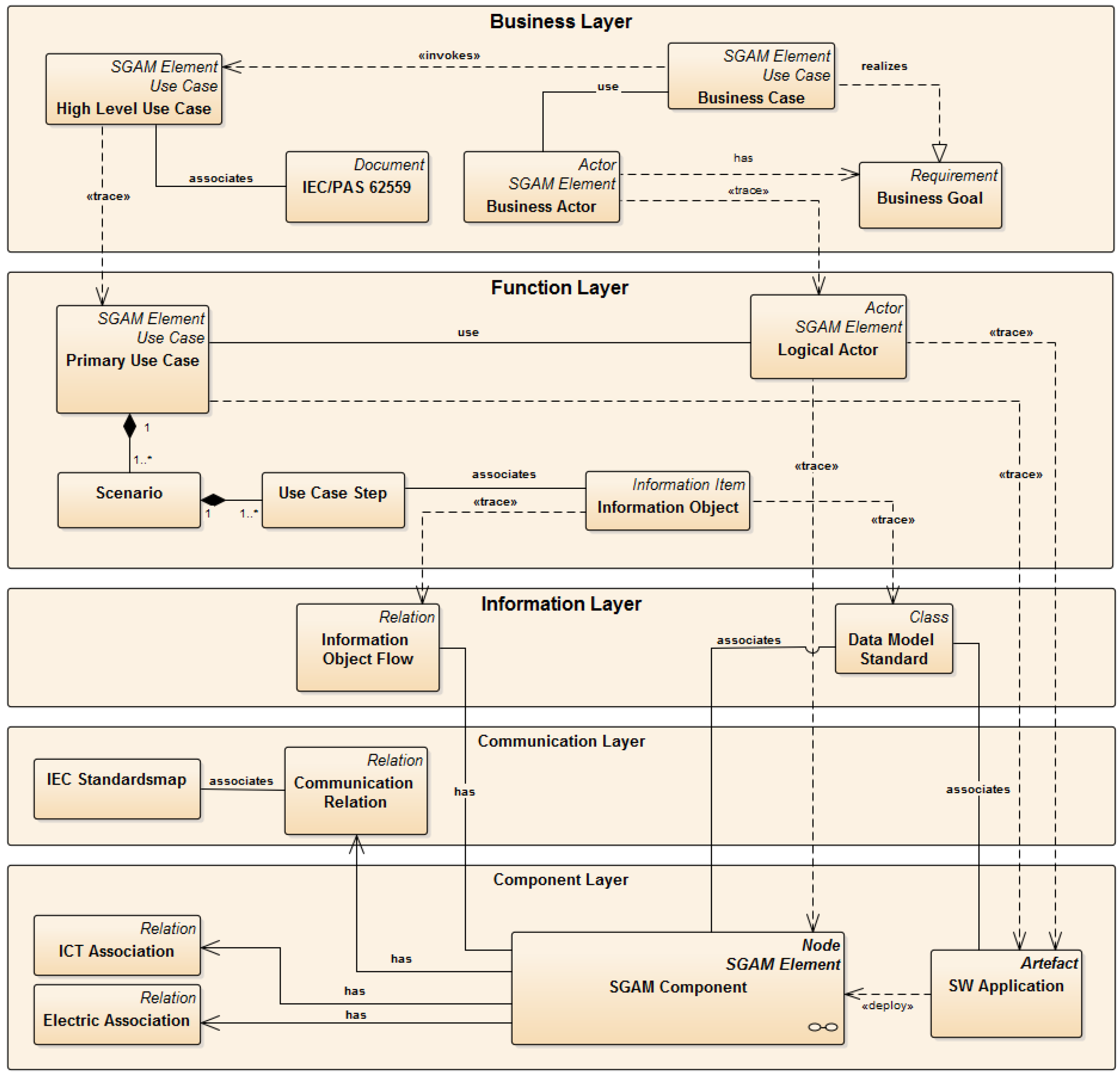
- Business Layer: Provides a business view on the information exchange related to Smart Grids. Regulatory and economic structures can be mapped on this layer.
- Function Layer: Describes functions and services including their relationships from an architectural viewpoint.
- Information Layer: Describes information objects being exchanged and the underlying canonical data models.
- Communication Layer: Describes protocols and mechanisms for the exchange of information between components.
- Component Layer: Physical distribution of all participating components including power system and ICT equipment.
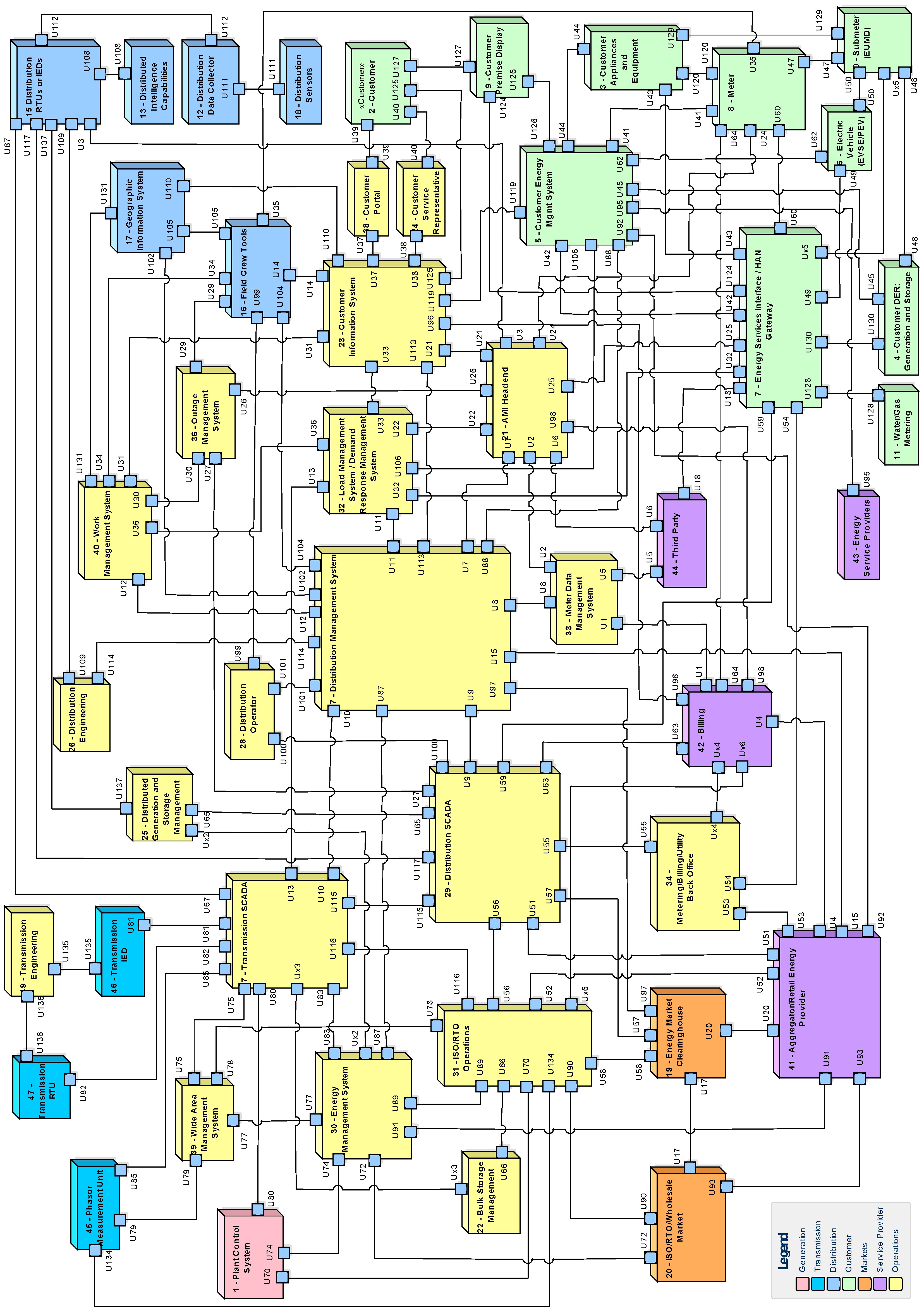
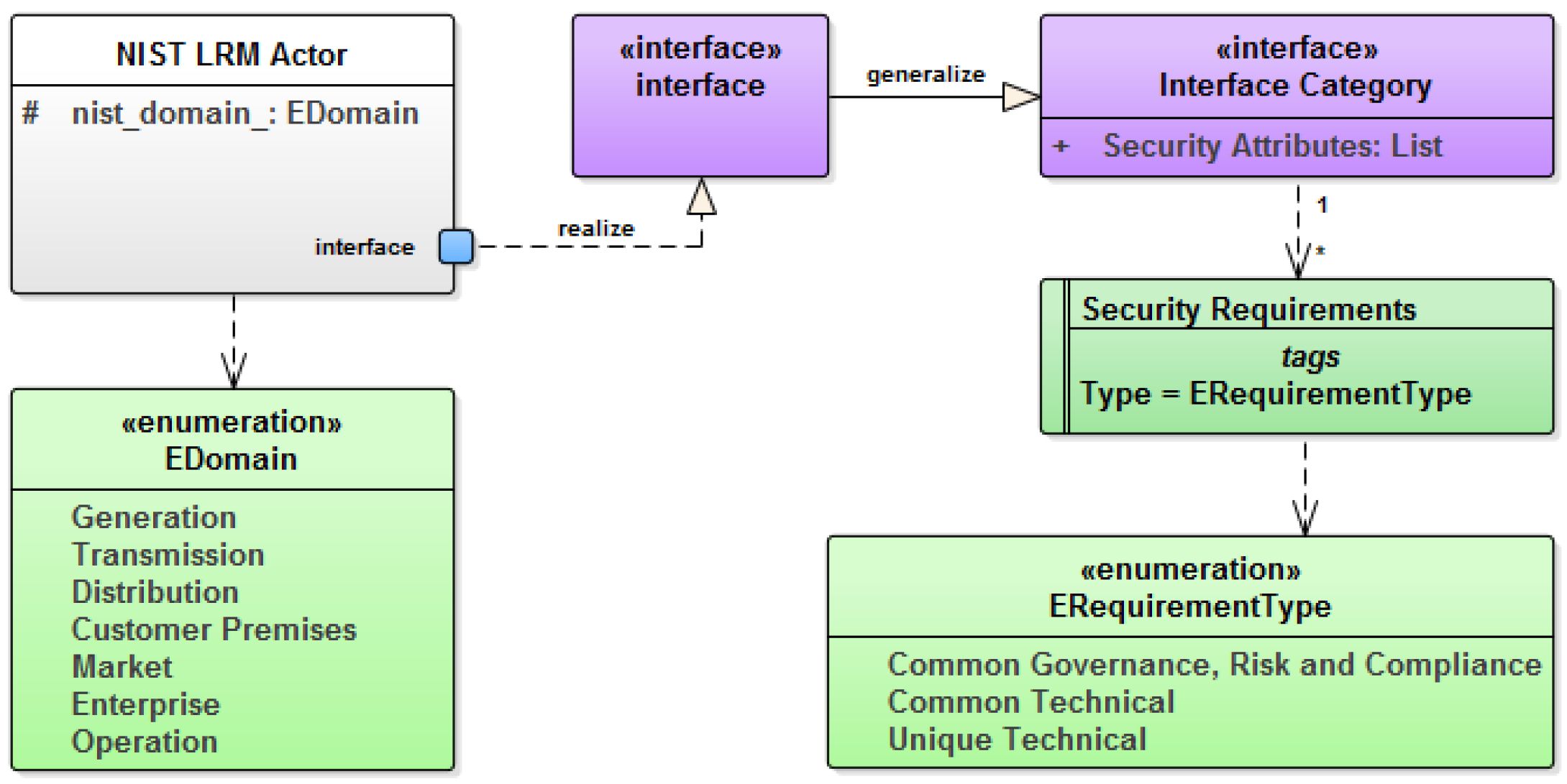
2.3. NIST Logical Reference Model
- Common Governance, Risk and Compliance Requirements;
- Common Technical Requirements;
- Unique Technical Requirements.
3. Conceptual Approach
3.1. Requirements
- Consistent and seamless development process covering Business Analysis, Functional Analysis, Architecture Development and Implementation;
- Integration of Security by Design over all development phases;
- Domain Specific Modeling Language (DSL) for development of architecture models;
- Utilization of best practice solutions (e.g., standard Use Cases or Reference Architecture) on basis of a common DSL;
- Capability for semi-automatic architecture evaluations;
- Conformity with and guideline for usage of existing standards;
- Seamless integration with implementation framework for particular systems.
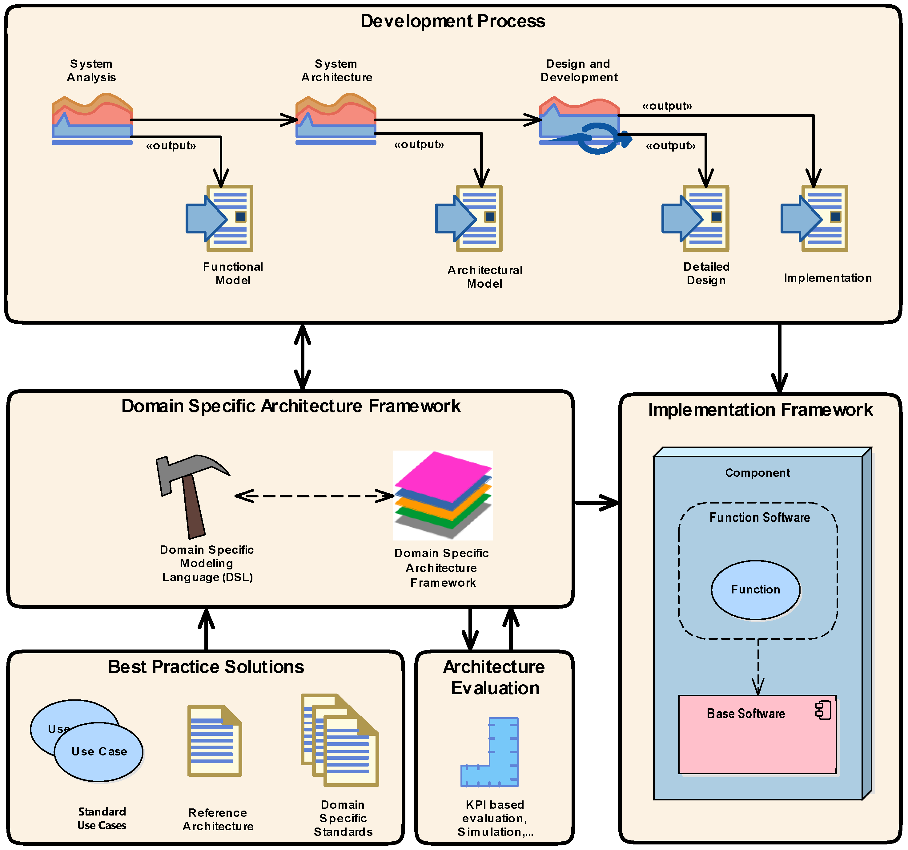
3.2. Building Blocks
- Development Process
- Domain Specific Architecture Framework
- Best Practice Solutions
- Architecture Evaluation
- Implementation Framework
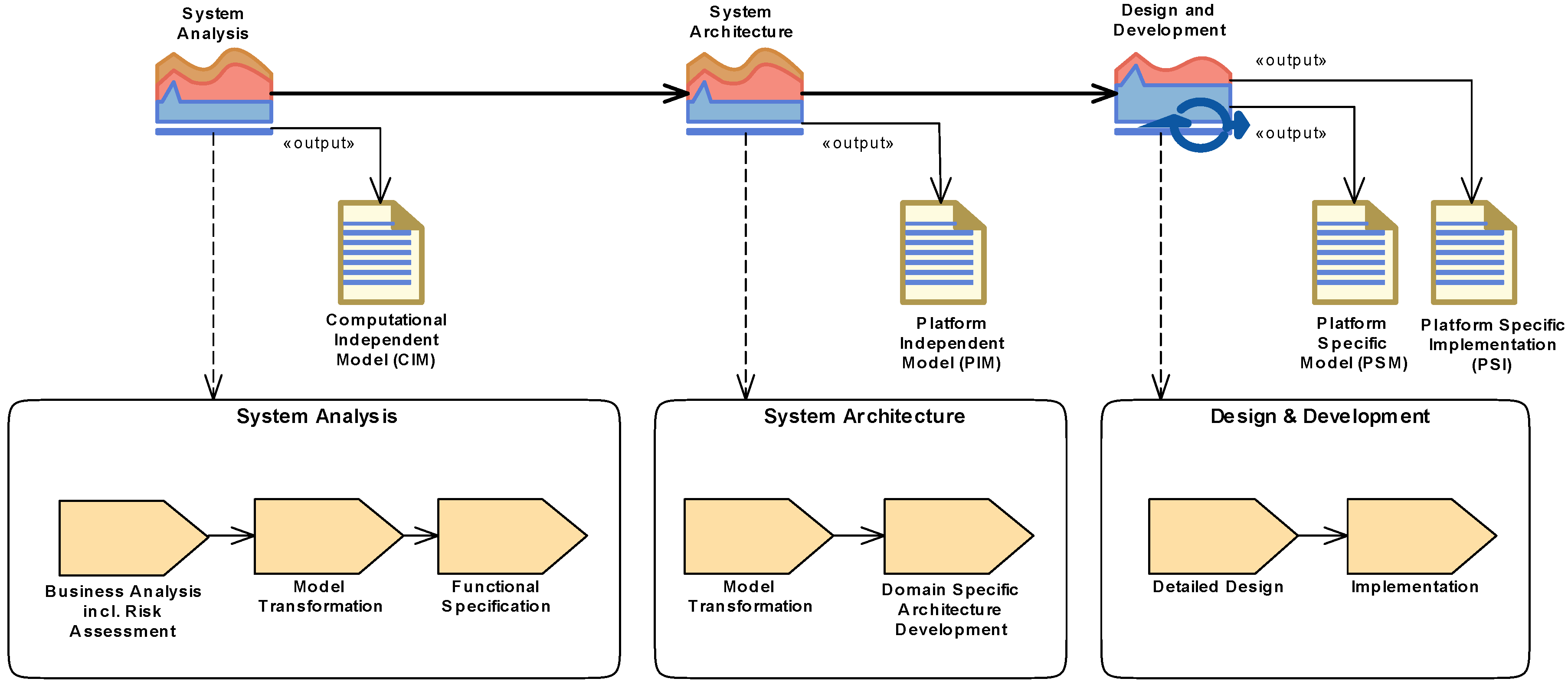
- System Analysis Phase
- System Architecture Phase
- Design and Development Phase
4. Implementation
4.1. Development Process
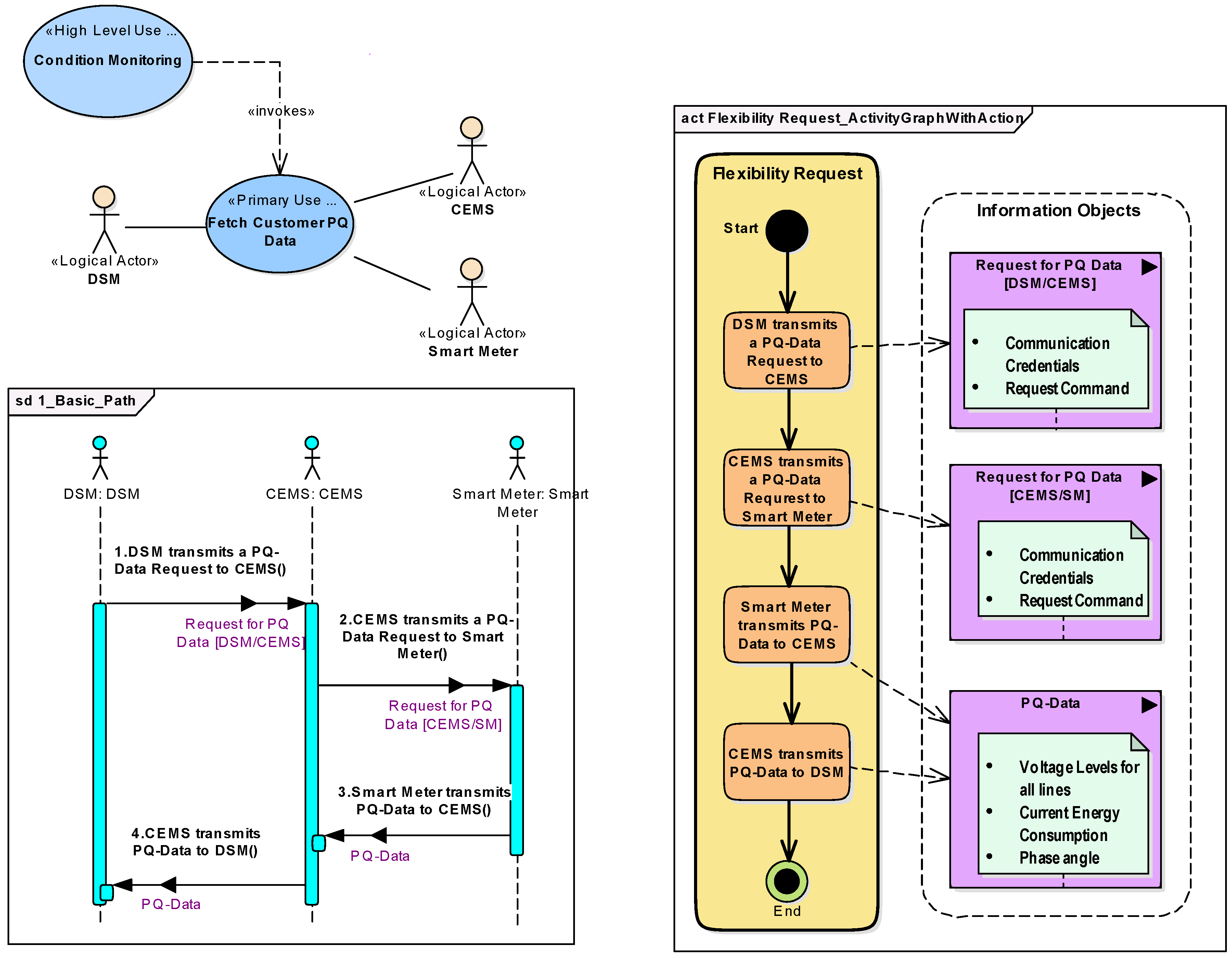
4.1.1. System Analysis Phase
- <Actor 1> <performs action>
- <Actor 1> <transmitts information | triggers Action> <to|on> <Actor 2>
- DSM transmits a PQ-Data Request to CEMS
- CEMS transmits a PQ-Data Request to Smart Meter
- Smart Meter transmits PQ-Data to CEMS
- CEMS transmits PQ-Data to DSM
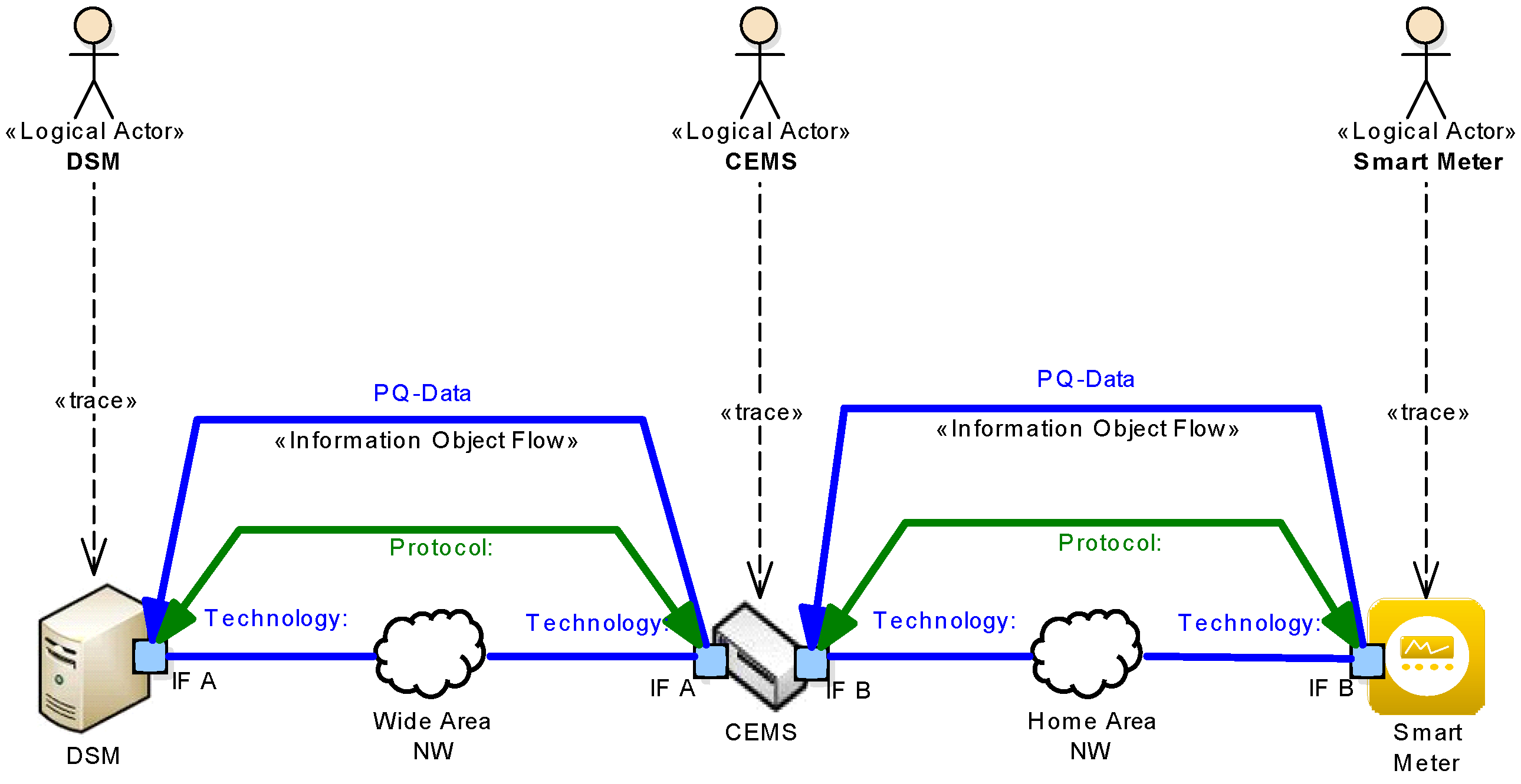
4.1.2. System Architecture Phase
4.1.3. Design and Development Phase
4.2. Domain Specific Architecture Framework
4.3. Architecture Evaluation
4.4. Best Practice Solutions
4.4.1. Use Case Management
4.4.2. Reference Architecture
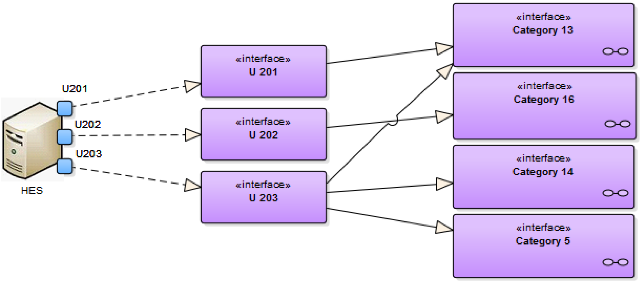
4.4.3. Standards Mapping
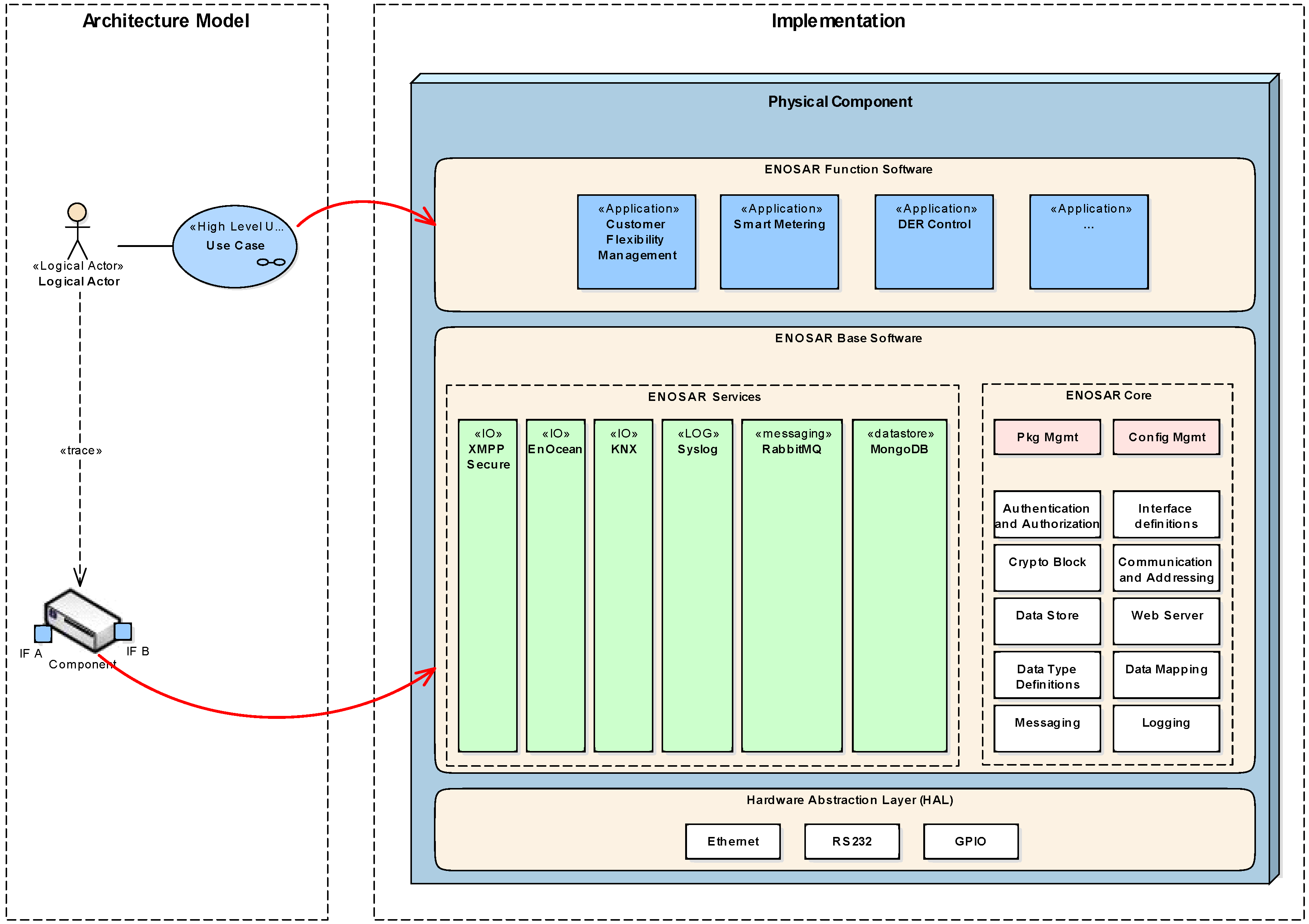
4.5. Implementation Framework
- Stronger formalization of functionality
- Model-to-Code transformation
- Partitioning of the ENOSAR Base Software (e.g., where to locate which functionalities.)
- Integration of PETs
- Interfacing between base software and function software
5. Architecture Modeling Example
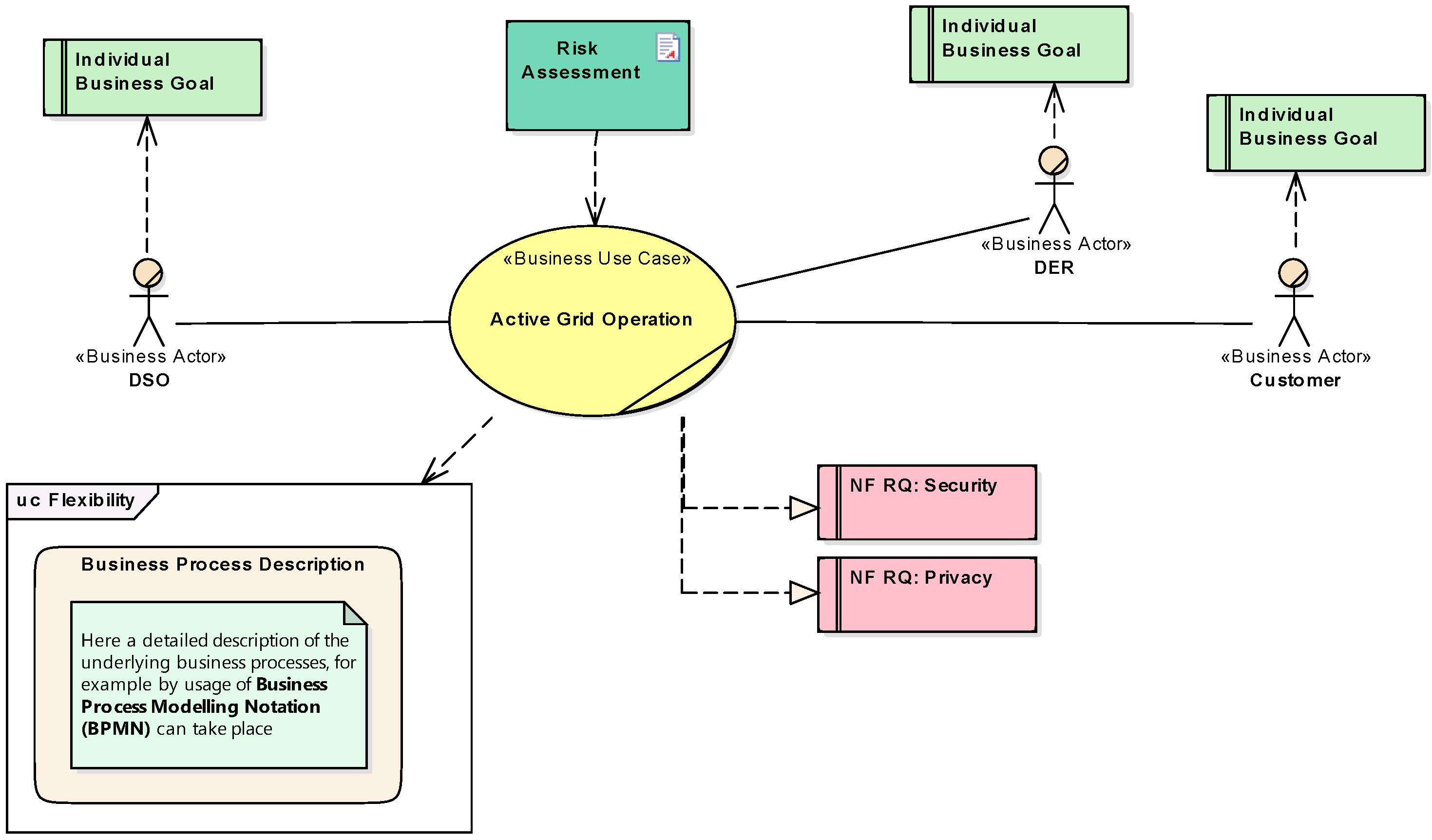
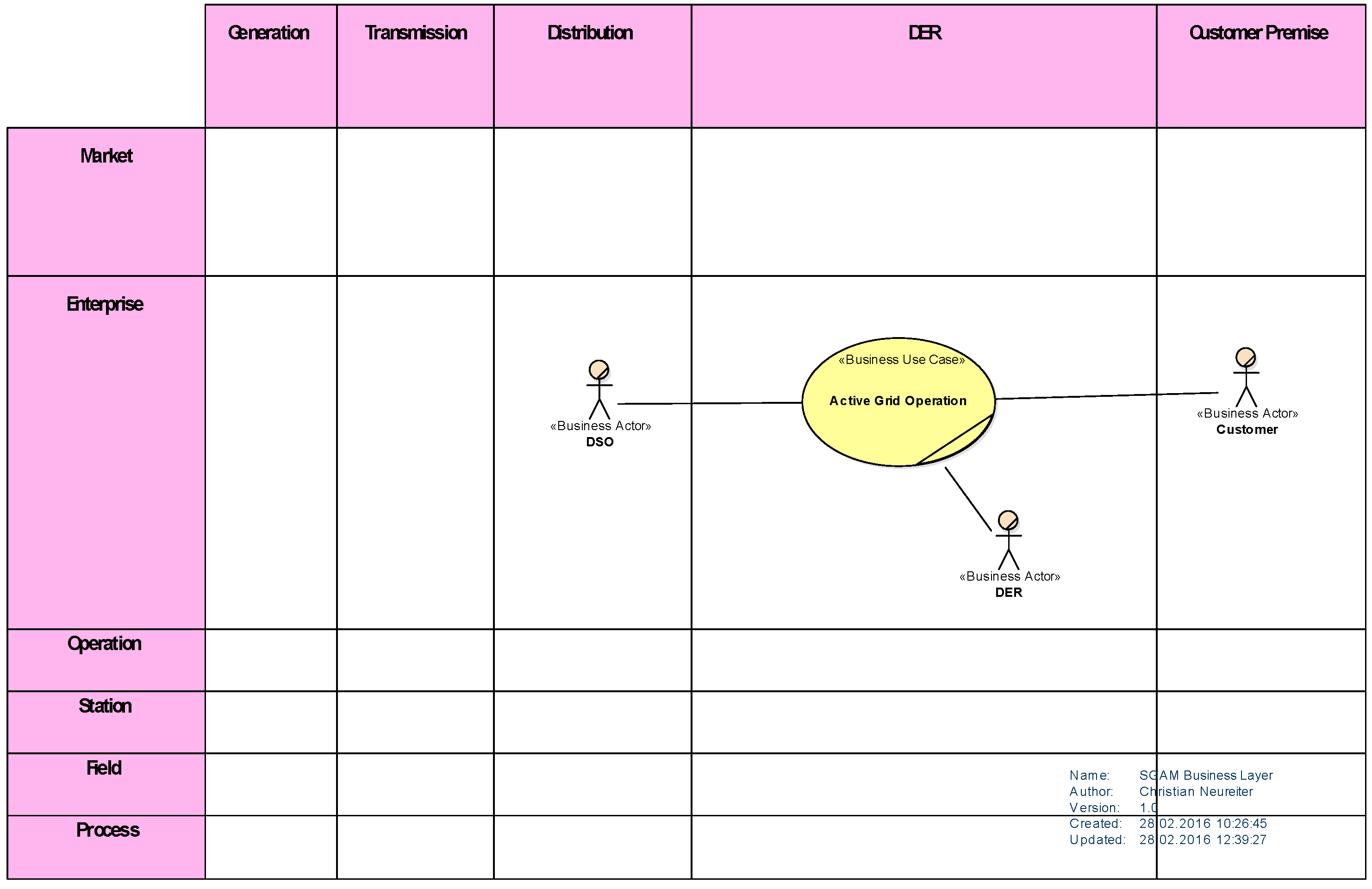
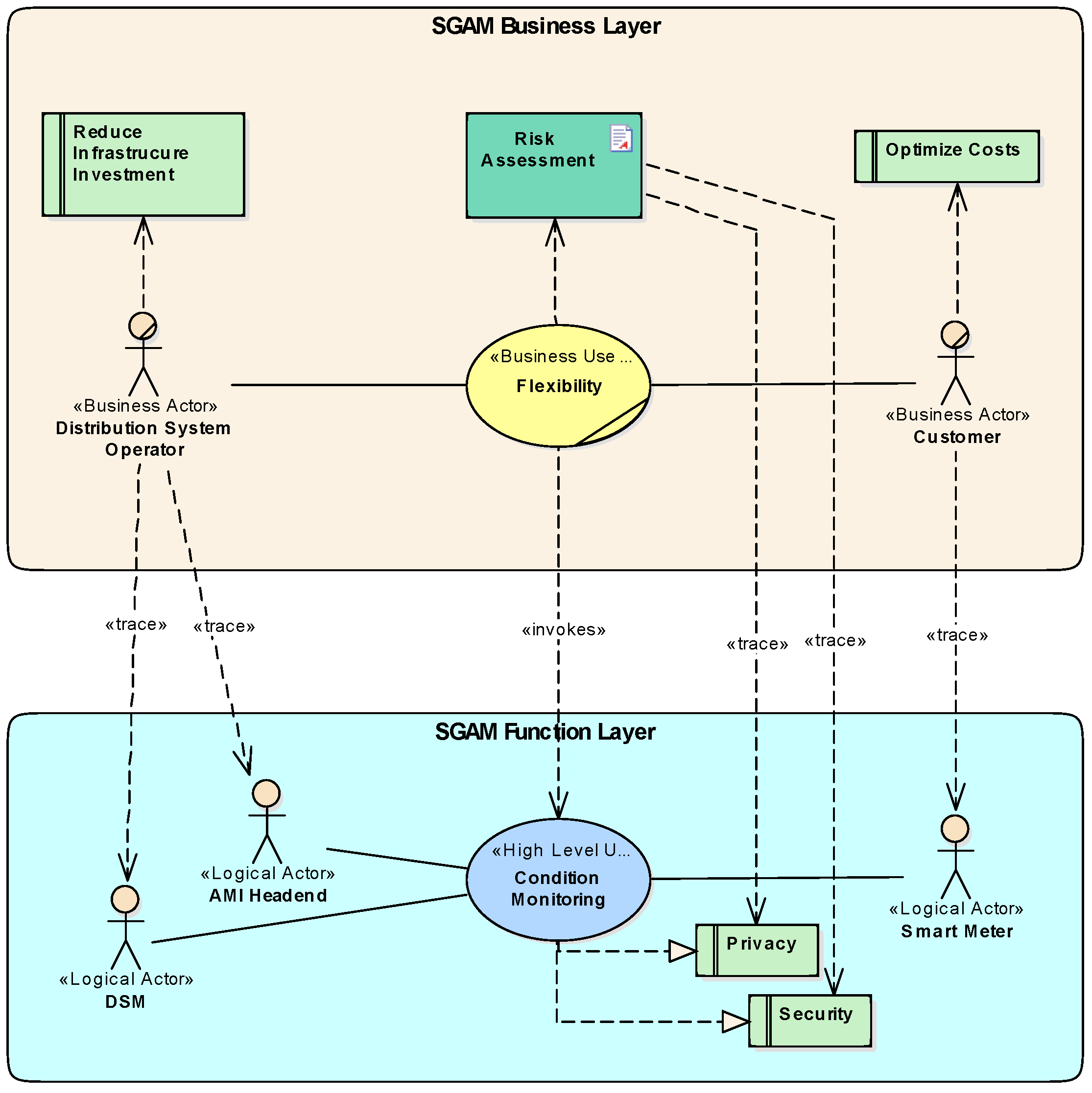
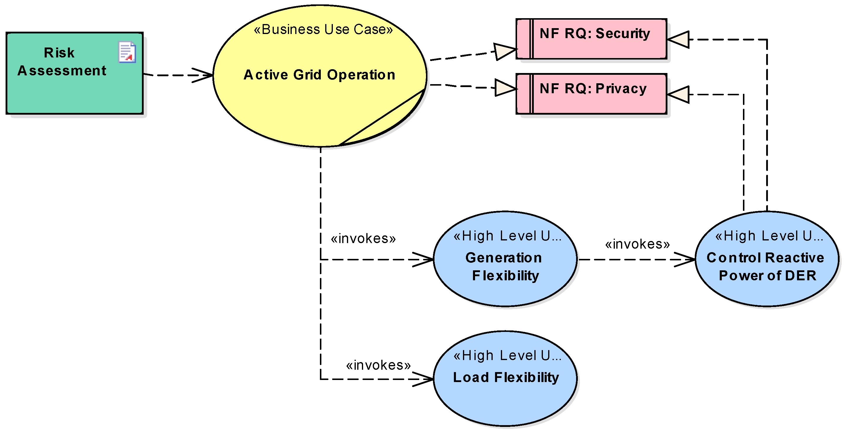
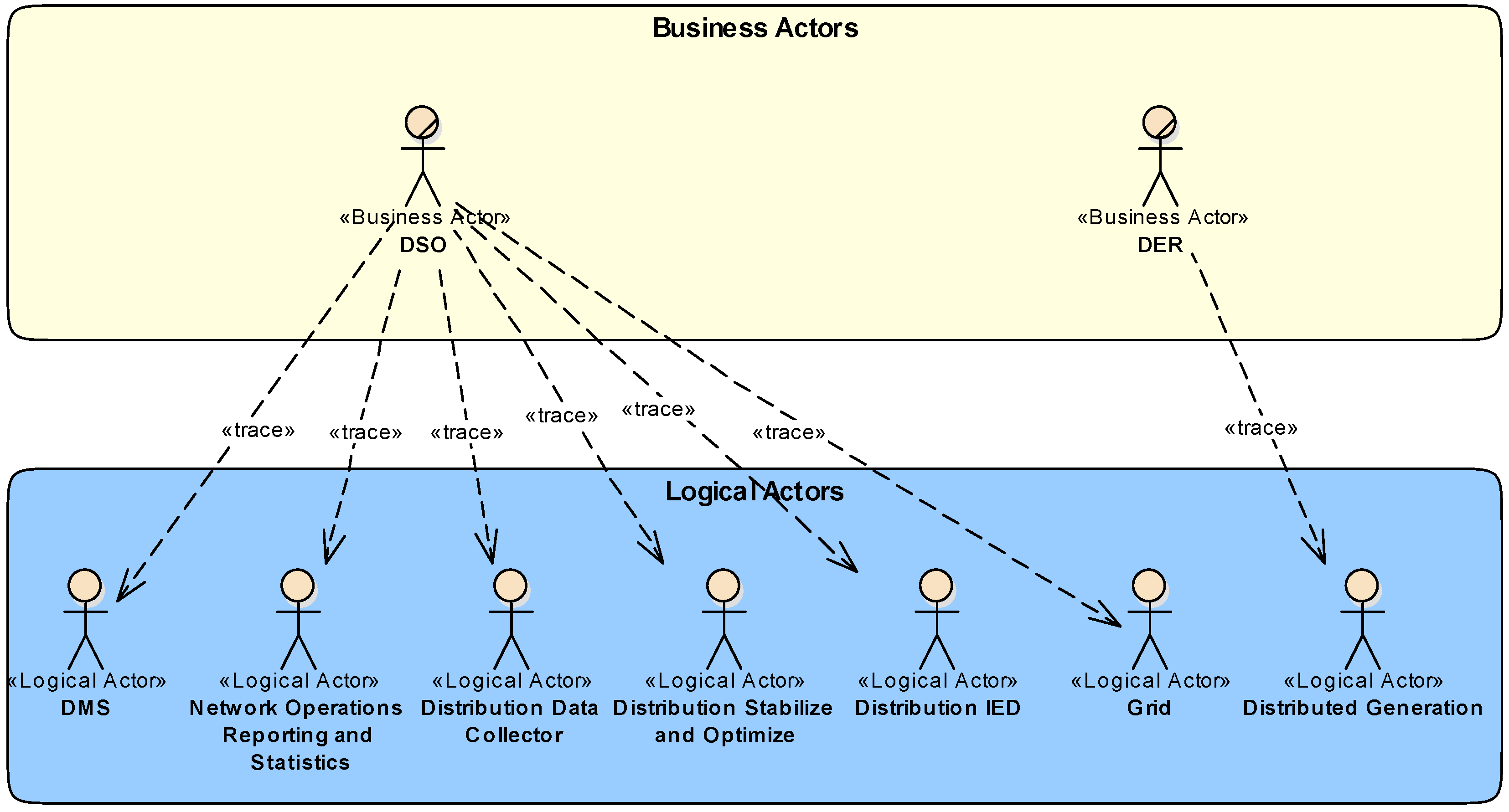
5.1. System Analysis—Business Layer
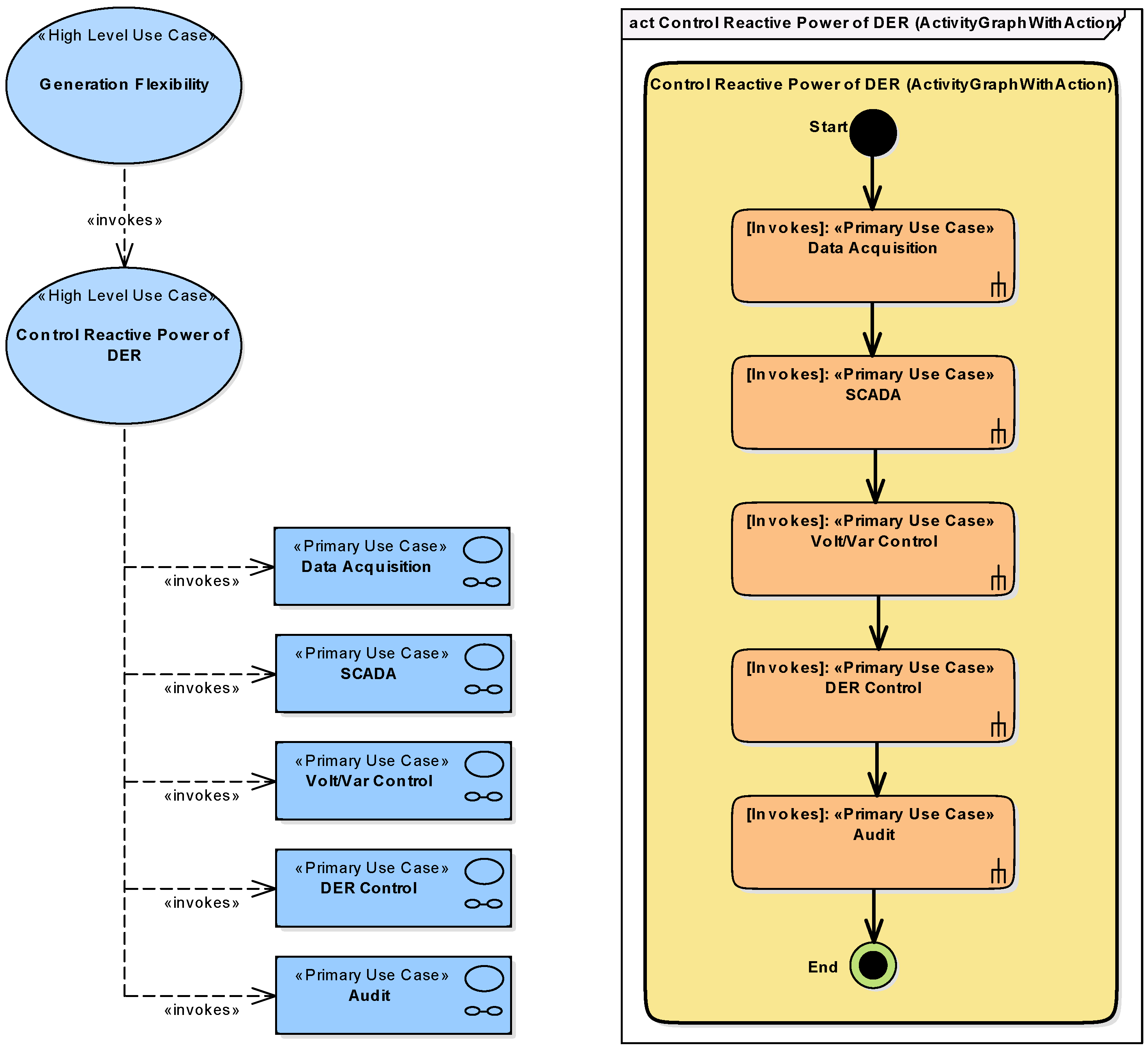
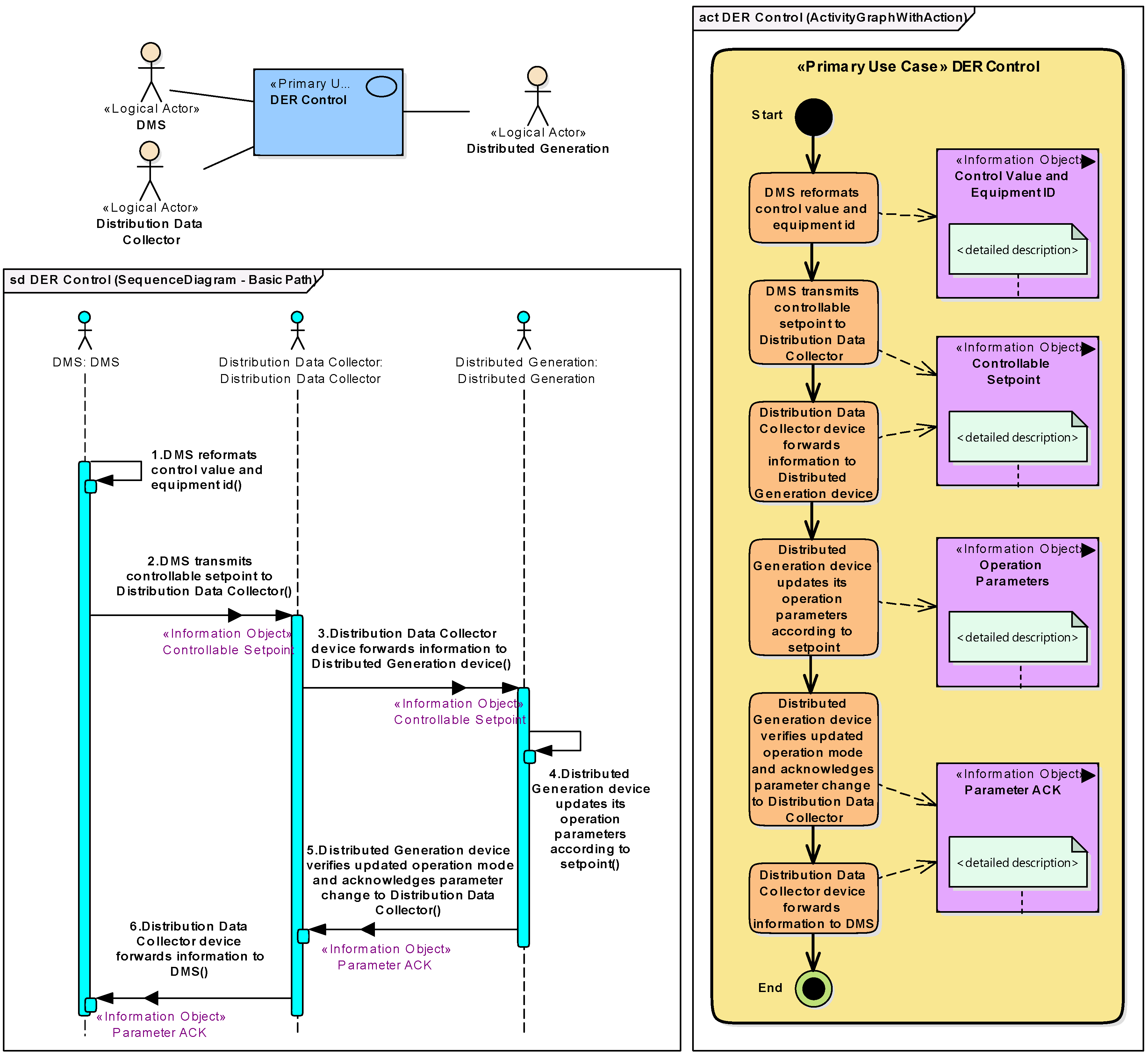
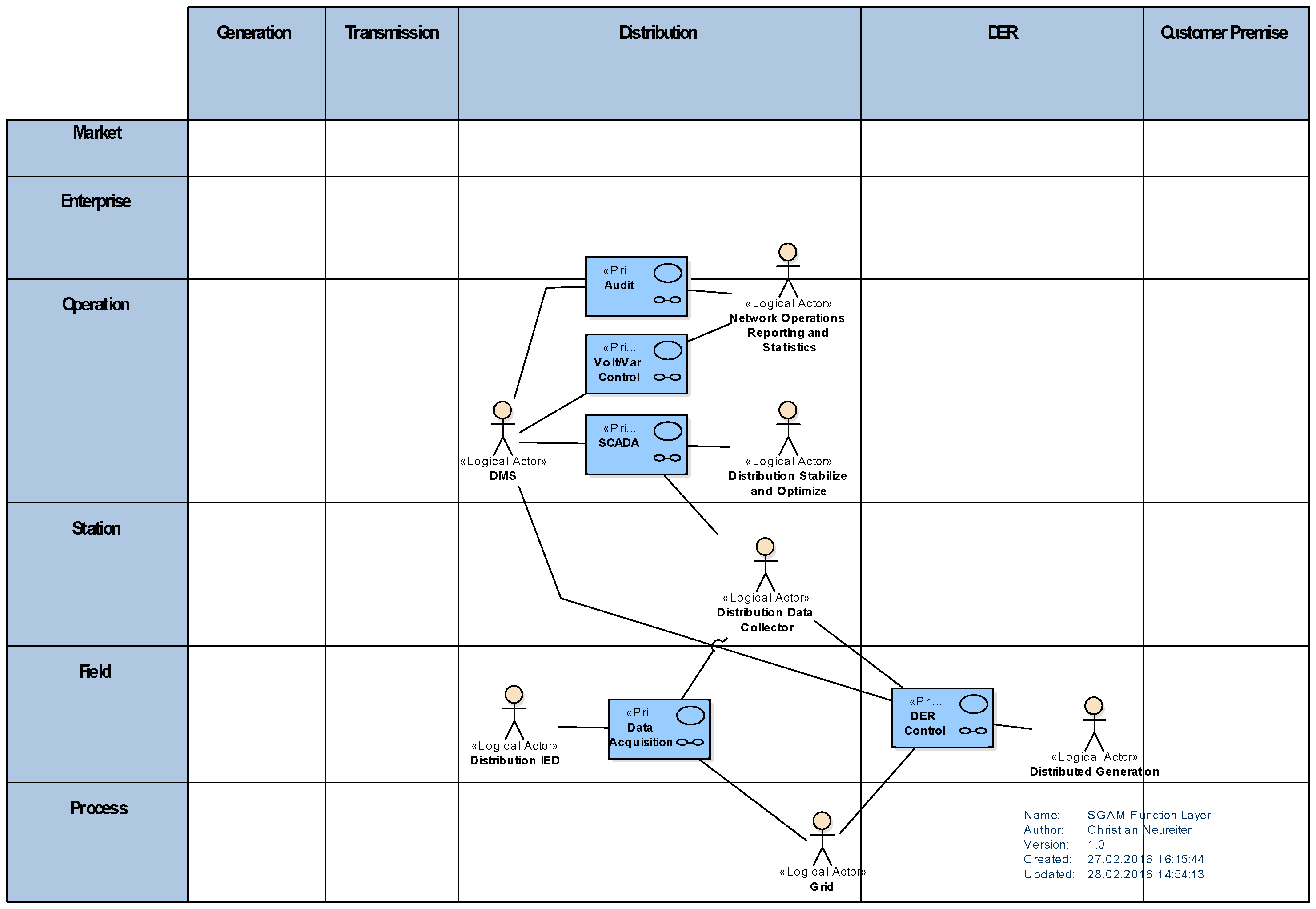
5.2. System Analysis—Function Layer
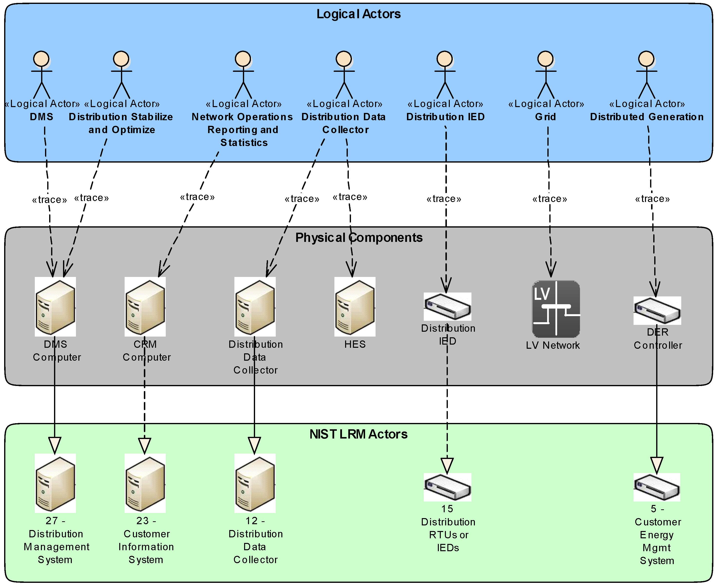
5.3. Model Transformation
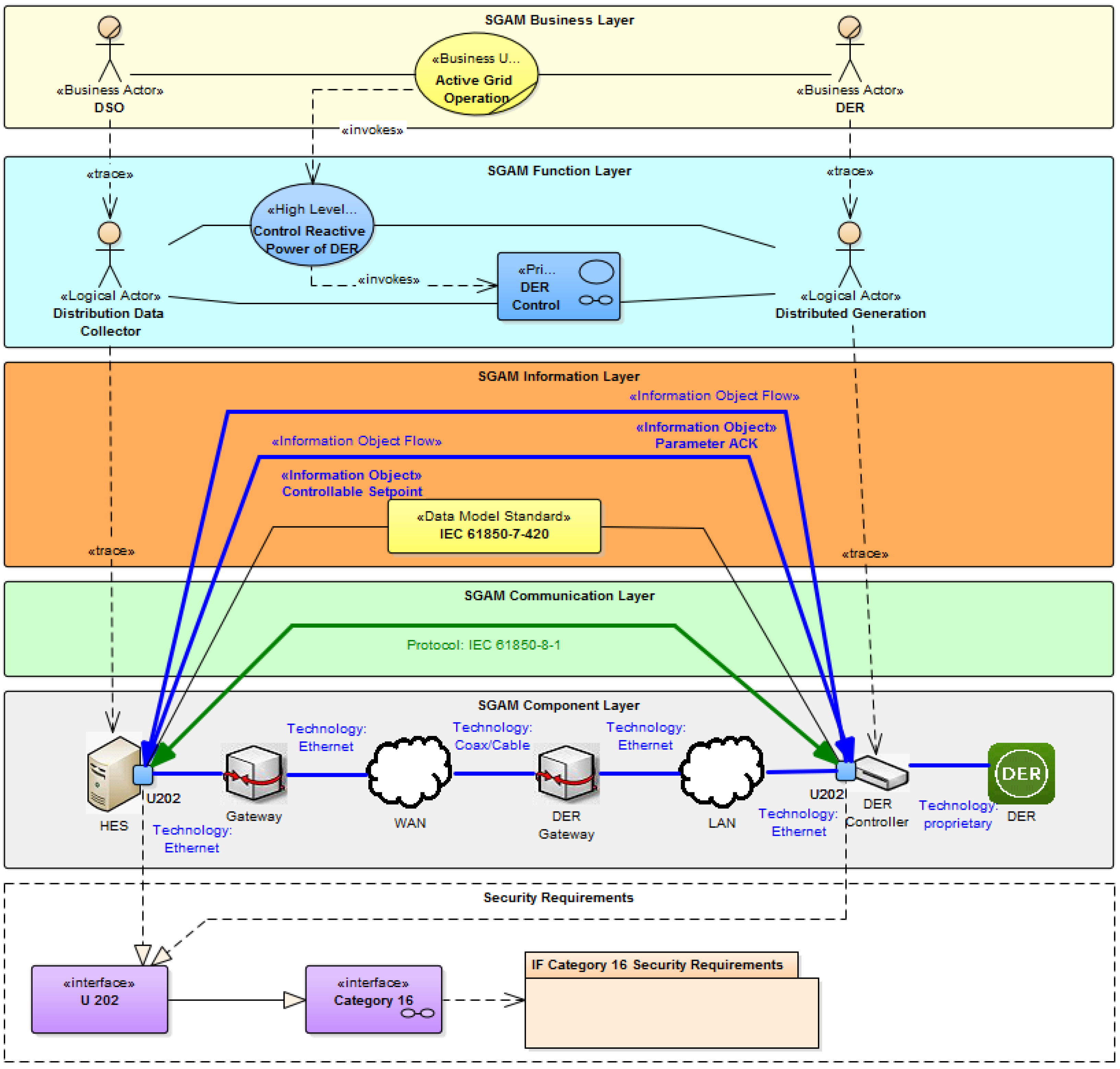
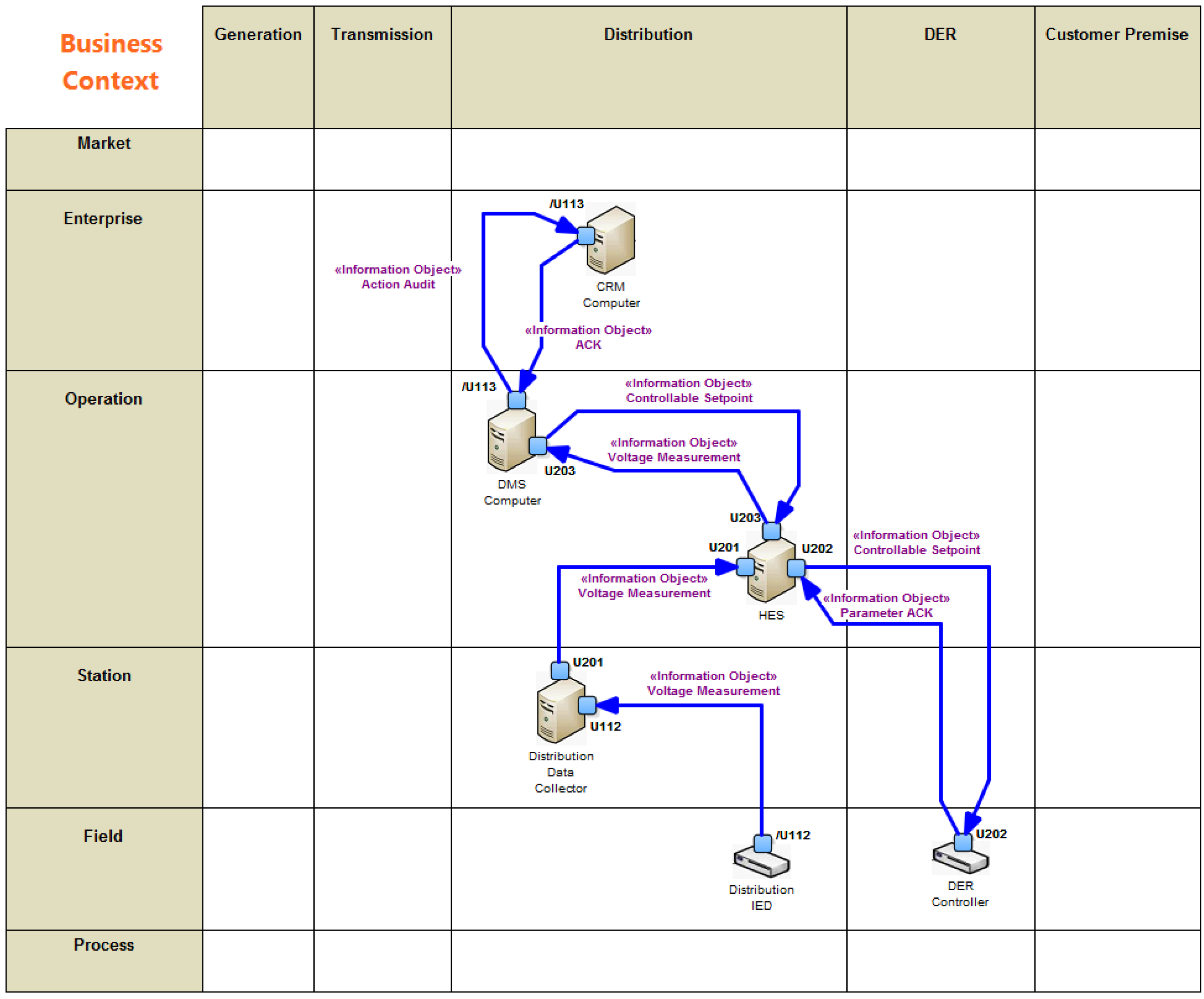
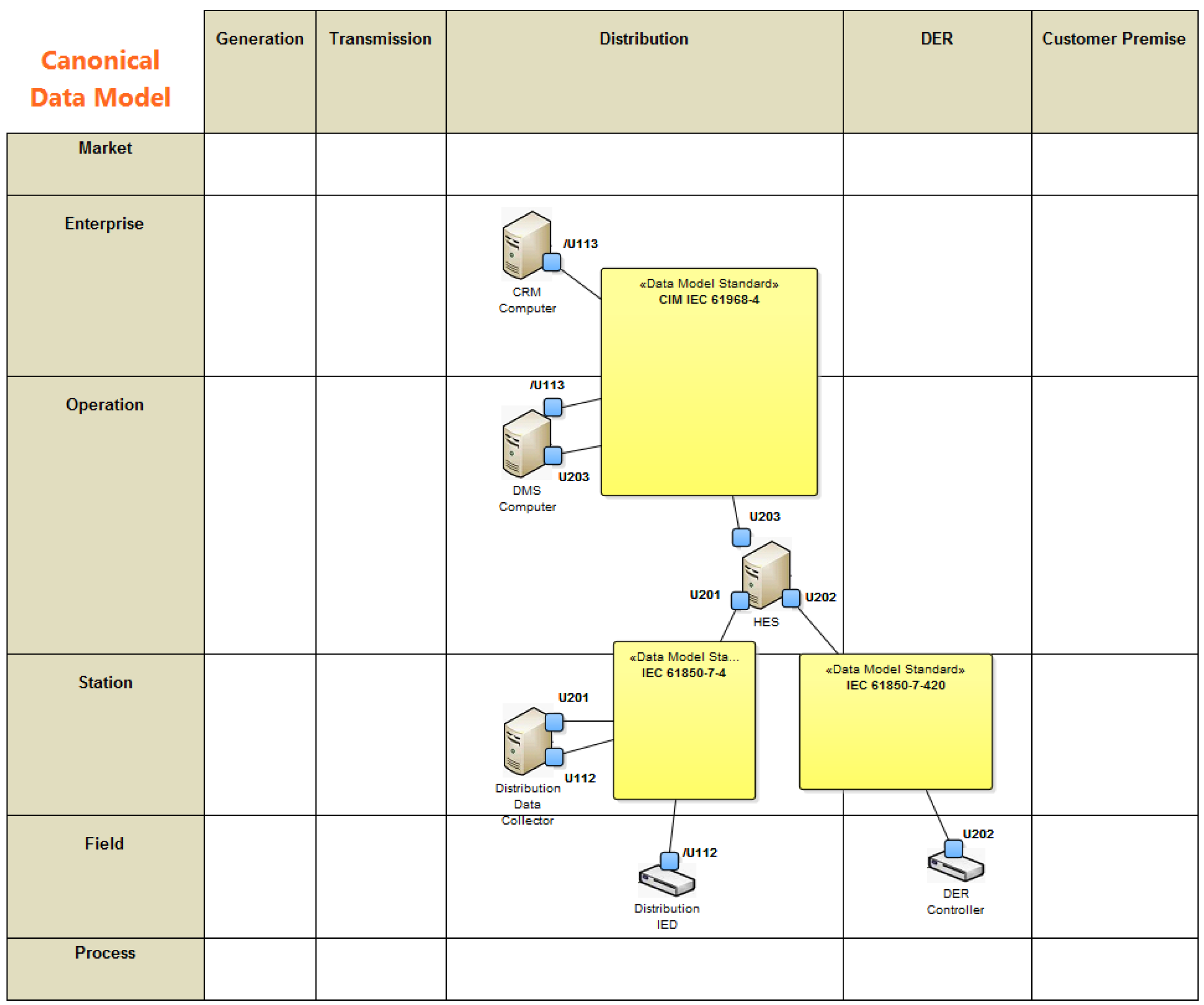
5.4. System Architecture—Information Layer
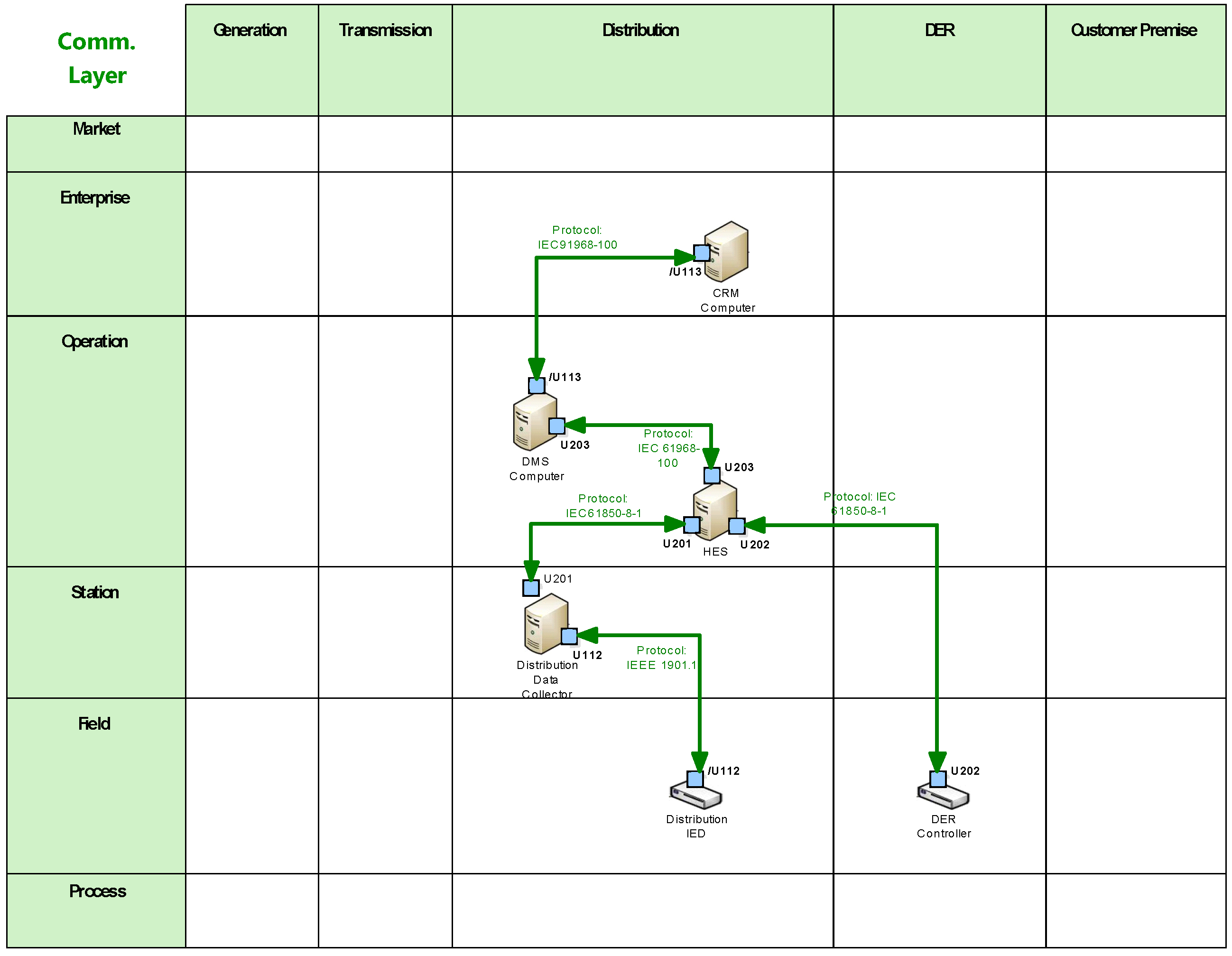
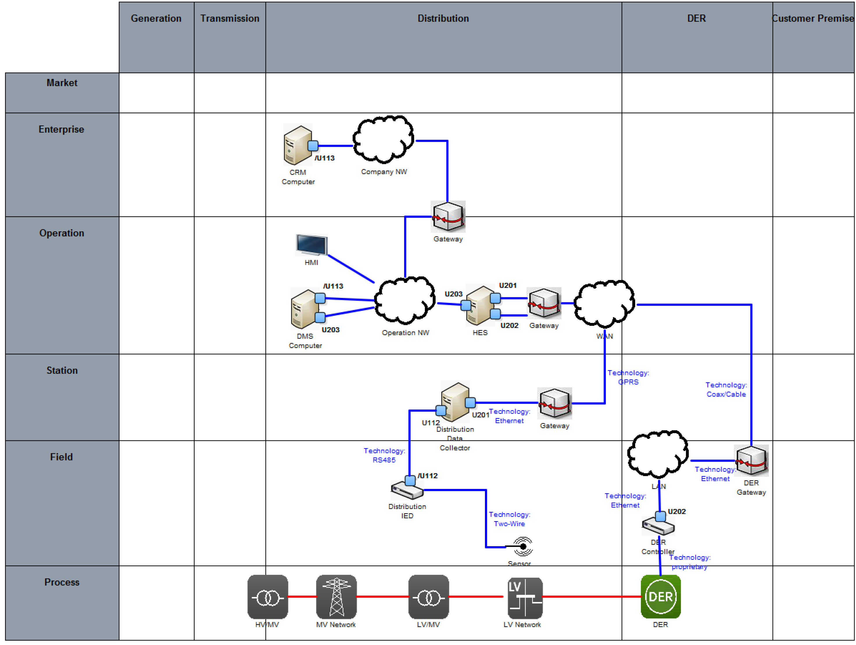
5.5. System Architecture—Communication Layer
5.6. System Architecture—Component Layer
5.7. Further Processing
6. Conclusions
Acknowledgments
Author Contributions
Conflicts of Interest
References
- Electronic Power Research Institute. Vision for a Holistic Power Supply and Delivery Chain; Technical Report 1018587; EPRI: Palo Alto, CA, USA, 2009. [Google Scholar]
- Fang, X.; Misra, S.; Xue, G.; Yang, D. Smart Grid—The New and Improved Power Grid: A Survey. IEEE Commun. Surv. Tutor. 2011, 99, 1–37. [Google Scholar] [CrossRef]
- Lo, C.; Ansari, N. The Progressive Smart Grid System from Both Power and Communications Aspects. IEEE Commun. Surv. Tutor. 2011, 14, 799–821. [Google Scholar] [CrossRef]
- Gungor, V.C.; Sahin, D.; Kocak, T.; Ergut, S.; Buccella, C.; Cecati, C.; Hancke, G.P. Smart Grid Technologies: Communication Technologies and Standards. IEEE Trans. Ind. Inform. 2011, 7, 529–539. [Google Scholar] [CrossRef]
- Farhangi, H. The path of the smart grid. IEEE Power Energy Mag. 2010, 8, 18–28. [Google Scholar] [CrossRef]
- Haberfellner, R.; de Weck, O.L.; Fricke, E.; Vössner, S. Systems Engineering. Grundlagen und Anwendung; Orell Füssli: Zürich, Switzerland, 2012. [Google Scholar]
- Brown, R.E. Impact of Smart Grid on distribution system design. In Proceedings of the 2008 IEEE Power and Energy Society General Meeting—Conversion and Delivery of Electrical Energy in the 21st Century, Pittsburgh, PA, USA, 20–24 July 2008; pp. 1–4.
- Moslehi, K.; Kumar, R. A Reliability Perspective of the Smart Grid. IEEE Trans. Smart Grid 2010, 1, 57–64. [Google Scholar] [CrossRef]
- Fan, Z.; Kulkarni, P.; Gormus, S.; Efthymiou, C.; Kalogridis, G.; Sooriyabandara, M.; Zhu, Z.; Lambotharan, S.; Chin, W. Smart Grid Communications: Overview of Research Challenges, Solutions, and Standardization Activities. IEEE Commun. Surv. Tutor. 2013, 15, 21–38. [Google Scholar] [CrossRef]
- Yan, Y.; Qian, Y.; Sharif, H.; Tipper, D. A Survey on Smart Grid Communication Infrastructures: Motivations, Requirements and Challenges. IEEE Commun. Surv. Tutor. 2013, 15, 5–20. [Google Scholar] [CrossRef] [Green Version]
- Gungor, V.C.; Sahin, D.; Kocak, T.; Ergut, S.; Buccella, C.; Cecati, C.; Hancke, G.P. A Survey on Smart Grid Potential Applications and Communication Requirements. IEEE Trans. Ind. Inform. 2013, 9, 28–42. [Google Scholar] [CrossRef]
- McDaniel, P.; McLaughlin, S. Security and Privacy Challenges in the Smart Grid. IEEE Secur. Priv. Mag. 2009, 7, 75–77. [Google Scholar] [CrossRef]
- Khurana, H.; Hadley, M.; Lu, N.; Frincke, D.A. Smart-Grid Security Issues. IEEE Secur. Priv. 2010, 8, 81–85. [Google Scholar] [CrossRef]
- US Department of Energy. The Smart Grid: An Introduction; US Department of Energy: Washington, DC, USA, 2008.
- Paverd, A.J.; Martin, A.P. Hardware Security for Device Authentication in the Smart Grid. In Smart Grid Security; Springer: Berlin, Germany, 2013; pp. 72–84. [Google Scholar]
- Mo, Y.; Kim, T.H.J.; Brancik, K.; Dickinson, D.; Lee, H.; Perrig, A.; Sinopoli, B. Cyber Physical Security of a Smart Grid Infrastructure. Proc. IEEE 2012, 100, 195–209. [Google Scholar]
- The Smart Grid Interoperability Panel—Cyber Security Working Group. Guidelines for Smart Grid Cyber Security; Technical Report NISTIR 7628; National Institute of Standards and Technology (NIST): Gaithersburg, MD, USA, 2010; Volume 1–3.
- Smart Grid Coordination Group. First Set of Standards; CEN-CENELEC-ETSI Smart Grid Coordination Group: Brussels, Belgium, 2012. [Google Scholar]
- Smart Grid Coordination Group. Sustainable Processes; CEN-CENELEC-ETSI Smart Grid Coordination Group: Brussels, Belgium, 2012. [Google Scholar]
- Smart Grid Coordination Group. Smart Grid Reference Architecture; CEN-CENELEC-ETSI Smart Grid Coordination Group: Brussels, Belgium, 2012. [Google Scholar]
- Smart Grid Coordination Group. Smart Grid Information Security; CEN-CENELEC-ETSI Smart Grid Coordination Group: Brussels, Belgium, 2012. [Google Scholar]
- Schumacher, M.; Fernandez-Buglioni, E.; Hybertson, D.; Buschmann, F.; Sommerlad, P. Security Patterns: Integrating Security and Systems Engineering; John Wiley: Hoboken, NJ, USA, 2006. [Google Scholar]
- Schmidt, D.C. Model-driven engineering. IEEE Comput. Soc. 2006, 39, 25. [Google Scholar] [CrossRef]
- Kent, S. Model Driven Engineering. In Integrated Formal Methods; Springer: Berlin, Germany, 2002; pp. 286–298. [Google Scholar]
- Bézivin, J. In search of a basic principle for model driven engineering. Novatica J. Spec. Issue 2004, 5, 21–24. [Google Scholar]
- Favre, J.M. Towards a basic theory to model model driven engineering. In Proceedings of the 3rd Workshop in Software Model Engineering, Lisbon, Portugal, 11–15 October 2004; pp. 262–271.
- Object Management Group. OMG Unified Modeling Language (OMG UML), Superstructure; Object Management Group: Needham, MA, USA, 2009. [Google Scholar]
- Object Management Group. OMG Unified Modeling Language (OMG UML), Infrastructure; Object Management Group: Needham, MA, USA, 2009. [Google Scholar]
- Object Management Group. OMG Systems Modeling Language (OMG SysML) Version 1.2; Object Management Group: Needham, MA, USA, 2010. [Google Scholar]
- Jürjens, J. UMLsec: Extending UML for secure systems development. In “UML” 2002—The Unified Modeling Language; Springer: Berlin, Germany, 2002; pp. 412–425. [Google Scholar]
- Roudier, Y.; Apvrille, L. SysML-Sec: A model driven approach for designing safe and secure systems. In Proceedings of the 2015 3rd International Conference onModel-Driven Engineering and Software Development (MODELSWARD), Angers, France, 9–11 February 2015; pp. 655–664.
- Van Deursen, A.; Klint, P.; Visser, J. Domain-Specific Languages: An Annotated Bibliography. Sigplan Not. 2000, 35, 26–36. [Google Scholar] [CrossRef]
- Hudak, P. Modular domain specific languages and tools. In Proceedings of the 5th International Conference on Software Reuse, Pittsburgh, PA, USA, 20–24 July 1998; pp. 134–142.
- Mernik, M.; Heering, J.; Sloane, A.M. When and how to develop domain-specific languages. ACM Comput. Surv. CSUR 2005, 37, 316–344. [Google Scholar] [CrossRef]
- Fowler, M. Domain-Specific Languages; Pearson Education: Boston, MA, USA, 2010. [Google Scholar]
- Andrén, F.; Stifter, M.; Strasser, T. Towards a Semantic Driven Framework for Smart Grid Applications: Model-Driven Development Using CIM, IEC 61850 and IEC 61499. Inform. Spektrum 2013, 36, 58–68. [Google Scholar] [CrossRef]
- Brédillet, P.; Lambert, E.; Schultz, E. CIM, 61850, COSEM standards used in a Model Driven Integration approach to build the Smart Grid Service Oriented Architecture. In Proceedings of the First IEEE International Conference on Smart Grid Communications (SmartGridComm), Gaithersburg, MD, USA, 4–6 Ocotober 2010; pp. 467–471.
- Lopes, A.J.; Lezama, R.; Pineda, R. Model Based Systems Engineering for Smart Grids as Systems of Systems. Procedia Comput. Sci. 2011, 6, 441–450. [Google Scholar] [CrossRef]
- Kaitovic, I.; Lukovic, S. Adoption of Model-Driven methodology to aggregations design in Smart Grid. In Proceedings of the 9th IEEE International Conference on Industrial Informatics, Lisbon, Portugal, 26–29 July 2011; pp. 533–538.
- Object Management Group. Model Driven Architecture (MDA) MDA Guide rev 2.0. Whitepaper. Available online: http://www.omg.org/cgi-bin/doc?ormsc/14-06-01.pdf (accessed on 27 May 2016).
- Adolf, D.; Ferranti, E.; Koch, S. SmartScript—A domain-specific language for appliance control in Smart Grids. In Proceedings of the IEEE 3rd International Conference on Smart Grid Communications (SmartGridComm), Tainan, Taiwan, 5–8 November 2012; pp. 465–470.
- Schütte, S.; Scherfke, S.; Sonnenschein, M. Mosaik-smart grid simulation API. In Proceedings of SMARTGREENS 2012—International Conference on Smart Grids and Green IT Systems 2012, Porto, Portugal, 19–20 April 2012; pp. 14–24.
- Rohjans, S.; D’nekas, C.; Uslar, M. Requirements for Smart Grid ICT-Architectures. In Proceedings of the 3rd International Conference on Innovative Smart Grid Technologies Europe (ISGT Europe), Berlin, Germany, 14–17 October 2012; pp. 1–8.
- Trefke, J.; Rohjans, S.; Uslar, M.; Lehnhoff, S.; Nordström, L.; Saleem, A. Smart Grid Architecture Model use case management in a large European Smart Grid project. In Proceedings of the 4th Innovative Smart Grid Technologies Europe (ISGT Europe), Lyngby, Denmark, 6–9 October 2013; pp. 1–5.
- International Electrotechnical Commission. IEC 62559-2 Use Case Methodology—Part 2: Definition of the Templates for Use Cases, Actor List and Requirements List; IEC: Geneva, Switzerland, 2015. [Google Scholar]
- Office of the National Coordinator for Smart Grid Interoperability. NIST Framework and Roadmap for Smart Grid Interoperability Standards, Release 1.0; Institute of Standards and Technology (NIST): Gaithersburg, MD, USA, 2010.
- The GridWise Architecture Council. GridWise Interoperability Context-Setting Framework; The GridWise Architecture Council: Richland, WA, USA, 2008. [Google Scholar]
- Neureiter, C.; Uslar, M.; Engel, D.; Lastro, G. A Standards-based Approach for Domain Specific Modelling of Smart Grid System Architectures. In Proceedings of the 11th International Conference on System of Systems Engineering (SoSE), Kongsberg, Norway, 12–16 June 2016; 2016. [Google Scholar]
- Neureiter, C.; Engel, D.; Trefke, J.; Santodomingo, R.; Rohjans, S.; Uslar, M. Towards Consistent Smart Grid Architecture Tool Support: From Use Cases to Visualization. In Proceedings of the 5th International Conference on Innovative Smart Grid Technologies Europe (ISGT Europe), Istanbul, Turkey, 12–15 October 2014; pp. 1–6.
- Knirsch, F.; Engel, D.; Neureiter, C.; Frincu, M.; Prasanna, V. Model-driven Privacy Assessment in the Smart Grid. In Proceedings of the 1st International Conference on Information Systems Security and Privacy (ICISSP), Angers, France, 9–11 February 2015; pp. 173–181.
- Appelrath, H.J.; Beenken, P.; Bischofs, L.; Uslar, M. IT-Architekturentwicklung im Smart Grid. Perspektiven für eine Sichere markt-und Standardstandard Integration Erneuerbarer Energien; Springer: Berlin, Germany, 2012. [Google Scholar]
- Uslar, M.; Rosinger, C.; Schlegel, S. Security by Design for the Smart Grid: Combining the SGAM and NISTIR 7628. In Proceedings of the 38th International Computer Software and Applications Conference Workshops (COMPSACW), Vasteras, Sweden, 21–25 July 2014; pp. 110–115.
- European Network of Transmission System Operators for Electricity. The harmonised Electricity Market Role Model; European Network of Transmission System Operators for Electricity: Brussels, Belgium, 2014. [Google Scholar]
- Mattle, P.; Neureiter, C.; Kupzog, F. Projekt SGMS—INTEGRA Übergang zu netz- und marktgeführtem Betrieb im Smart Grid. In Proceedings of the 4th Workshop on Communications for Energy Systems; Austrian Electrotechnical Association: Vienna, Austria, 26 September 2013; pp. 44–52. [Google Scholar]
- Engel, D.; Eibl, G. Multi-Resolution Load Curve Representation with Privacy-preserving Aggregation. In Proceedings of IEEE Innovative Smart Grid Technologies (ISGT), Lyngby, Denmark, 6–9 October 2013; pp. 1–5.
- Engel, D. Wavelet-based Load Profile Representation for Smart Meter Privacy. In Proceedings IEEE PES Innovative Smart Grid Technologies (ISGT’13), Washington, DC, USA, 24–27 February 2013; pp. 1–6.
- Engel, D.; Eibl, G. Wavelet-Based Multiresolution Smart Meter Privacy. IEEE Trans. Smart Grid 2016, 99, 1–12. [Google Scholar] [CrossRef]
- Neureiter, C.; Eibl, G.; Engel, D.; Schlegel, S.; Uslar, M. A concept for engineering smart grid security requirements based on SGAM models. In Computer Science—Research and Development; Springer: Berlin, Germany, 2014; pp. 1–7. [Google Scholar]


| Abbreviation | Meaning |
|---|---|
| BA | Business Actor |
| BC | Business Case |
| BG | Business Goal |
| CIM | Common Information Model |
| DDC | Distributed Data Collector |
| DER | Distributed Energy Resource |
| DSM | Distribution System Management |
| DSO | Distribution System Operator |
| HES | Head End System |
| HLUC | High Level Use Case |
| IF | Interface |
| IO | Information Object |
| LA | Logical Actor |
| PUC | Primary Use Case |
| WAN | Wide Area Network |
© 2016 by the authors; licensee MDPI, Basel, Switzerland. This article is an open access article distributed under the terms and conditions of the Creative Commons Attribution (CC-BY) license (http://creativecommons.org/licenses/by/4.0/).
Share and Cite
Neureiter, C.; Engel, D.; Uslar, M. Domain Specific and Model Based Systems Engineering in the Smart Grid as Prerequesite for Security by Design. Electronics 2016, 5, 24. https://doi.org/10.3390/electronics5020024
Neureiter C, Engel D, Uslar M. Domain Specific and Model Based Systems Engineering in the Smart Grid as Prerequesite for Security by Design. Electronics. 2016; 5(2):24. https://doi.org/10.3390/electronics5020024
Chicago/Turabian StyleNeureiter, Christian, Dominik Engel, and Mathias Uslar. 2016. "Domain Specific and Model Based Systems Engineering in the Smart Grid as Prerequesite for Security by Design" Electronics 5, no. 2: 24. https://doi.org/10.3390/electronics5020024