Article

FPGA-Based Real-Time Motion Detection for Automated Video Surveillance Systems

1
CSIR—Central Electronics Engineering Research Institute (CSIR-CEERI), Pilani 333031, Rajasthan, India
2
Electronic Science Department, Kurukshetra University, Kurukshetra 136119, Haryana, India
*
Author to whom correspondence should be addressed.
These authors contributed equally to this work.
Electronics 2016, 5(1), 10; https://doi.org/10.3390/electronics5010010
Submission received: 21 December 2015 / Revised: 23 February 2016 / Accepted: 4 March 2016 / Published: 11 March 2016

Abstract

:
Design of automated video surveillance systems is one of the exigent missions in computer vision community because of their ability to automatically select frames of interest in incoming video streams based on motion detection. This research paper focuses on the real-time hardware implementation of a motion detection algorithm for such vision based automated surveillance systems. A dedicated VLSI architecture has been proposed and designed for clustering-based motion detection scheme. The working prototype of a complete standalone automated video surveillance system, including input camera interface, designed motion detection VLSI architecture, and output display interface, with real-time relevant motion detection capabilities, has been implemented on Xilinx ML510 (Virtex-5 FX130T) FPGA platform. The prototyped system robustly detects the relevant motion in real-time in live PAL (720 × 576) resolution video streams directly coming from the camera.

Graphical Abstract

1. Introduction

The importance of motion detection for designing an automated video surveillance system can be gauged from the availability of a large number of robust and complex algorithms that have been developed to-date, and the even larger number of articles that have been published on this topic so far. The problem of motion detection can be stated as “given a set of images of the same scene taken at several different times, the goal of motion detection is to identify the set of pixels that are significantly different between the last image of the sequence and the previous images” [1]. The simplest approach to motion detection is the frame differencing method in which motion detection can be achieved by finding the difference of the pixels between two adjacent frames. If the difference is higher than a threshold, the pixel is identified as foreground, otherwise background. The threshold is chosen empirically. Different methods and criteria for choosing the threshold have been surveyed and their comparative results have been reported in the literature [2,3,4]. Researchers have reported several motion detection methods that are closely related to simple differencing e.g., change vector analysis [5,6,7], image rationing [8], and frame differencing using sub-sampled gradient images [9]. The simplicity of frame differencing based approaches comes at the cost of motion detection quality. For a chosen threshold, simple differencing based approaches are unlikely to outperform the more advanced algorithms proposed for real-world surveillance applications. There are several other motion detection techniques such as predictive models [10,11,12,13,14], adaptive neural networks [15], and shading models [16,17,18]. A comprehensive description and comparative analysis of these methods has been presented by Radke et al. [1].
The practical real-world video surveillance applications demand a continuous updating of the background frame to incorporate any permanent scene change, for example, light intensity changes in the day time must be a part of the background. For this purpose, several researchers [19,20,21] have described adaptive background subtraction techniques for motion detection using a Gaussian Density Function. They are capable of handling illumination changes in a scene with stationary background scenarios.
Due to pseudo-stationary nature of the background in real-world scenes, assuming that background is perfectly stationary for surveillance applications is a serious flaw. For example, in a real-world video scene, there may be swaying branches of trees, moving tree leaves in windows of rooms, moving clouds, the ripples of water on a lake, or a moving fan in the room. These are small repetitive motions (typically not important) and so should be incorporated into background. The single background model based approaches mentioned above are incapable of correctly modeling such pseudo-stationary backgrounds. Stauffer and Grimson [22] recognized that these kinds of pseudo-stationary backgrounds are inherently multi-model and hence they developed the technique of an Adaptive Background Mixture Models, which models each pixel by a mixture of Gaussians. According to this method, every incoming pixel value is compared against the existing set of models at that location to find a match. If there is a match, the parameters of the matched model are updated and the incoming pixel is classified as a background pixel. If there is no match, the incoming pixel is motion pixel and the least-likely model (model having minimum weighted Gaussian) is discarded and replaced by a new one with incoming pixel as its mean and a high initial variance. However, maintaining these mixtures for every pixel is an enormous computational burden and results in low frame rates when compared to previous approaches. Butler et al. [23] proposed a new approach, similar to that of Stauffer and Grimson [22], but with a reduced computational complexity. The processing, in this approach, is performed on YCrCb video data format, but it still requires many mathematical computations and needs large amounts of memory for storing background models.
In parallel with the algorithm development, many researchers from VLSI design and system design research community published several research articles describing different hardware design based approaches to address the issue of real-time implementation of motion detection algorithms. These methods of hardware based motion detection reported in literature differ from each other due to design methodologies/approaches and design tool chains used. Based on design methodologies, various hardware based methods can be categorized as general purpose processor based approach, digital signal processor (DSP) based approach [24,25,26], complex programmable logic device (CPLD) based approach [27], application specific integrated circuit (ASIC) based approach [28,29], FPGA based hardware design approach [30,31,32,33,34,35,36,37,38,39,40,41,42,43,44,45,46,47,48,49], and FPGA based hardware/software co-design approach [50,51,52]. From design tool-chain perspective, the differences can be based on the use of VHDL/Verilog, high level hardware description language like Handle-C or SystemC, MATLAB-Simulink software, an Embedded Development kit, and a System Generator tool.
In current surveillance scenario, motion detection is one component of a potentially complex automated video surveillance system, intended to be used as a standalone system. Therefore, in addition to being accurate and robust, a successful motion detection technique must also be economic in the use of computational resources on FPGA development platform. This is because many other complex algorithms of an automated video surveillance system also run on the same FPGA platform. In order to address this problem of reducing the computational complexity, Chutani and Chaudhury [53] proposed a block-based clustering scheme with a very low complexity for motion detection. On one hand, this scheme is robust enough for handling pseudo-stationary nature of background, and on the other it significantly lowers the computational complexity and is well suited for designing standalone systems for real-time applications. For this reason we have selected the clustering based motion detection scheme for designing the real-time standalone motion detection system which features real-time processing and is capable of discarding irrelevant motion using adaptive background model. The implemented motion detection system can be used as a standalone system for automated video surveillance applications.

2. Motion Detection Algorithm

In this section, the clustering based motion detection scheme is briefly described. For more detailed description refer to [53] and [23]. Clustering based motion detection uses a block-based similarity computation scheme. To start with, each incoming video frame is partitioned into 4 × 4 pixel blocks. Each 4 × 4 pixel block is modeled by a group of four clusters where each cluster consists of a block centroid (in RGB) and a frame number which updated the cluster most recently. Optionally, for each block there may be a motion flag field. The group of four clusters is necessary to correctly model the pseudo-stationary background, as a single cluster is incapable of modeling multiple modes that can be present in pseudo-stationary backgrounds. The group size is selected as four because it has been reported by Chutani and Chaudhury [53] that four clusters per group yield a good balance between accuracy and computational complexity. The basic computational scheme is shown in Figure 1 and the pseudo-code is shown in Figure 2. The sequence of steps for motion detection using a clustering-based scheme is given below.
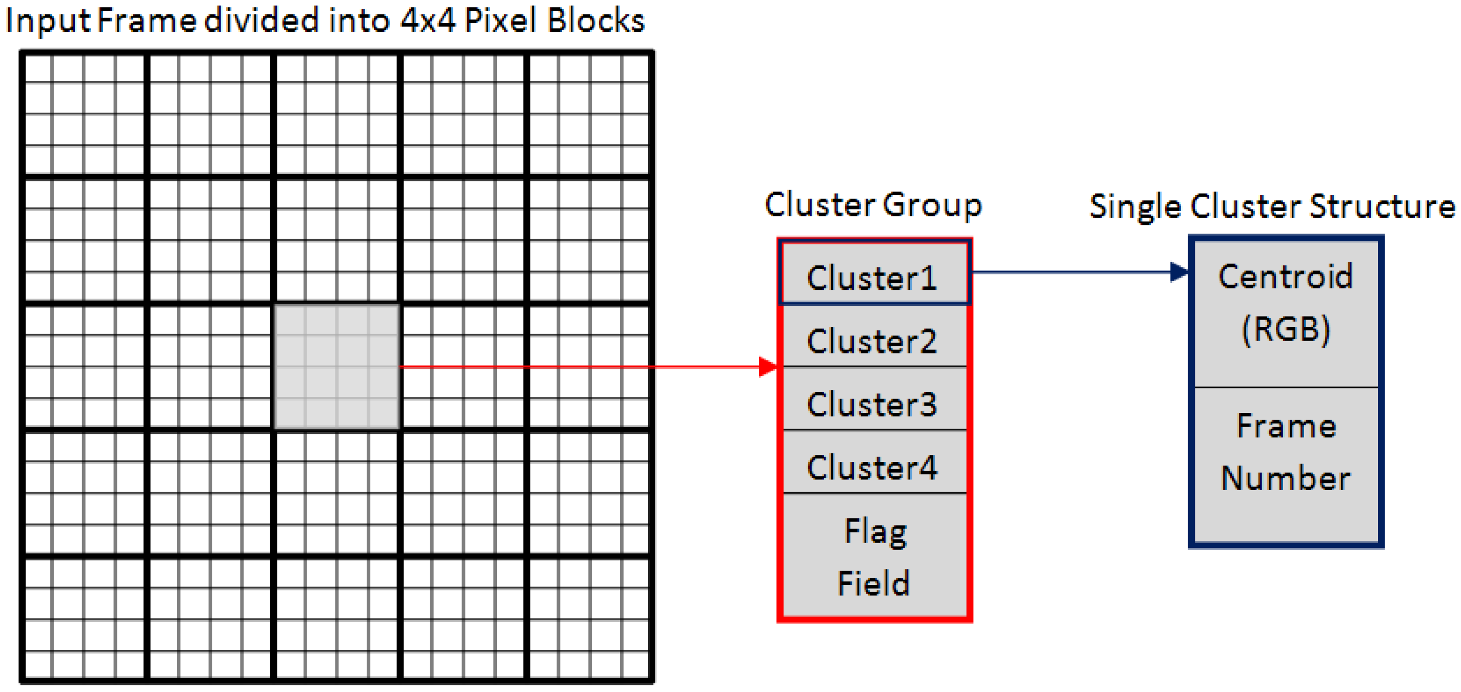
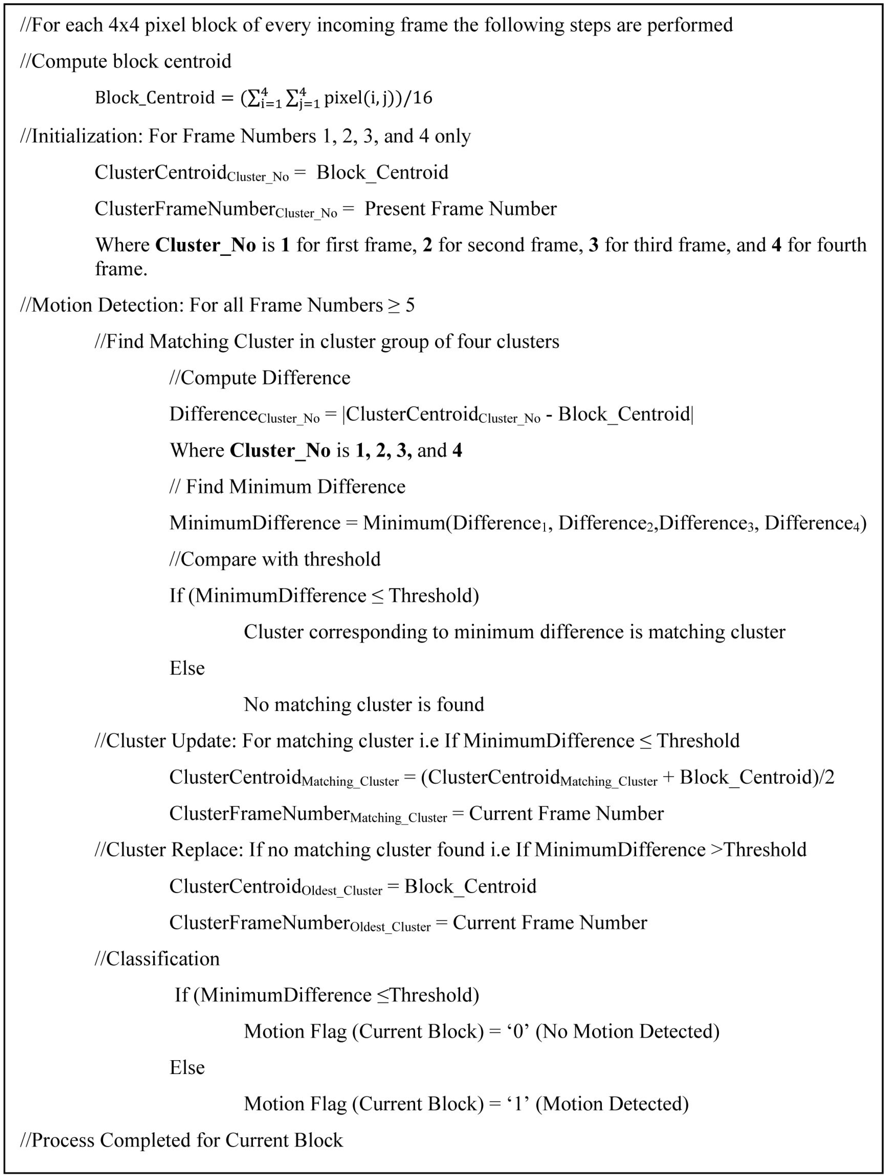
  • Block Centroid Computation: Each incoming frame is partitioned into 4 × 4 blocks. For each block, the block centroid for RGB color space is computed by taking the average color value of the 16 pixels of that block. The block centroid is of 24-bits (8-bits for each R, G, and B color component).
  • Cluster Group Initialization: During the initial four frames, initialization is performed. In the first frame, the first cluster of each block is initialized with its centroid set to the block centroid of corresponding block of the first frame and its frame number is set to 1. In the second frame, the second cluster of each block is initialized with its centroid set to the block centroid of the corresponding block of the second frame and its frame number is set to 2. In the third frame, the third cluster of each block is initialized with its centroid set to the block centroid of corresponding block of the third frame and its frame number is set to 3. In the fourth frame, the last/fourth cluster of each block is initialized with its centroid set to the block centroid of corresponding block of the fourth frame and its frame number is set to 4. In this way, during initialization all the four clusters of the cluster group are initialized.
  • Cluster Matching: After initialization, the next step for motion detection in incoming frames is to compare each of the incoming blocks against the corresponding cluster group. The goal is to find a matching cluster within the cluster group. For finding a matching cluster, for each cluster in the cluster group, the difference between its centroid and the incoming current block centroid is computed. The cluster with minimum centroid difference below the user defined threshold is considered as a matching cluster. In order to simplify this computation, Manhattan distance (sum of absolute differences) is used which avoids the overheads of multiplication in difference computation [23]. Eliminating multiplications is very beneficial in terms of reducing computational complexity of the algorithm as multiplications are costly in hardware.
  • Cluster Update: If, for a given block, a matching cluster is found within the cluster group, then the matching cluster is updated. The frame number of the matching cluster is replaced by the current frame number and the centroid of the matching cluster is replaced by the average value of the matching cluster centroid and the incoming current block centroid.
  • Cluster Replace: If, for a given block, no matching cluster could be found within the group, then the oldest cluster which has not been updated for the longest period of time (cluster with minimum frame number) is deleted and a new cluster is created having the current block centroid as its centroid and the current frame number as its frame number.
  • Classification: For a given block, if no matching cluster is found and the oldest cluster is replaced, then it implies that the incoming current block is not matching with the background models and it is marked as motion detected block by setting the motion flag field of the block to “1”. If a matching cluster is found within the cluster group and the matching cluster is updated, then the incoming current block belongs to the background and therefore, the motion flag field of the block is set to “0” (i.e., no motion detected).
The above-mentioned clustering-based motion detection scheme has been implemented by us in C/C++ programming language. For running the code, a Dell Precision T3400 workstation (with Windows XP operating system, quad-core Intel® Core™2 Duo Processor with 2.93 GHz Operating Frequency, and 4GB RAM) was used. The Open Computer Vision (OpenCV) libraries have been used in the code for reading video streams (either stored or coming from camera) and displaying motion detection results. The frame rate of this software-based implementation for standard PAL (720 × 576) resolution was much lower than the real-time requirements of automated video surveillance systems.

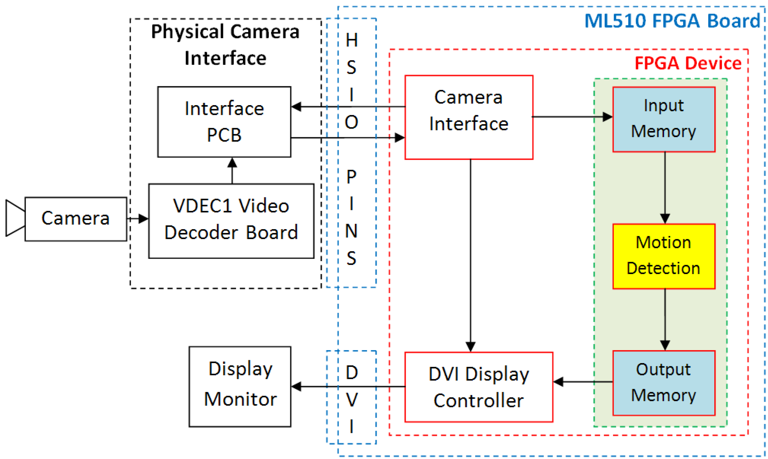
3. Motion Detection System

In order to achieve real-time performance, as required in an automated video surveillance system, we have proposed a dedicated hardware architecture for clustering-based motion detection scheme and its implementation as a prototype system using the Xilinx ML510 (Virtex-5 FX130T) FPGA board for real-time motion detection.
A simplified conceptual block diagram of the proposed and developed FPGA-based motion detection system is shown in Figure 3 to illustrate the data flow within the system. The main components of a complete FPGA-based standalone motion detection system are: analog Camera, VDEC1 Video Decoder Board for analog to digital video conversion, custom designed Interface PCB, Xilinx ML510 (Virtex-5 FX130T) FPGA platform for performing real-time motion detection, and a display device (Display Monitor).
Input video, captured by a Sony Analog Camera, is digitized by Digilent VDEC1 Video Decoder Board. The digital output signals from the video decoder board are transferred to FPGA platform using high speed I/O ports (HSIO PINS) available on Xilinx ML510 (Virtex-5 FX130T) FPGA Board using custom designed Interface PCB. The components inside dashed blue line are available on Xilinx ML510 (Virtex-5 FX130T) FPGA Board. These include FPGA Device (shown by dashed red line), High Speed Input Output Interface (HSIO PINS), and DVI Interface. The Camera Interface module uses the digital video signals available at the FPGA interface and extracts RGB data and generates Video Timing Signals. The DVI Display Controller is used to display the processed data on Display Monitor.
Data arrives from the Camera Interface module row by row. As the motion detection scheme is based on the processing of 4 × 4 image blocks, streaming video processing cannot be used for clustering based motion detection scheme. For this reason, the four rows of image data are buffered in Input Memory before processing begins. The Motion Detection architecture takes its input from the Input Memory and processes the data. The output of Motion Detection module is stored in Output Memory for synchronization purpose before sending it for display. This is because the output data of Motion Detection module is for 4 × 4 pixel block while the DVI Display Controller takes the input data row by row. The processed image pixel data from Output Memory along with video timing signals is sent for display on Display Monitor through DVI Interface available on FPGA board. The three modules (Input Memory, Motion Detection, and Output Memory) within green dashed line form the clustering based motion detection architecture.

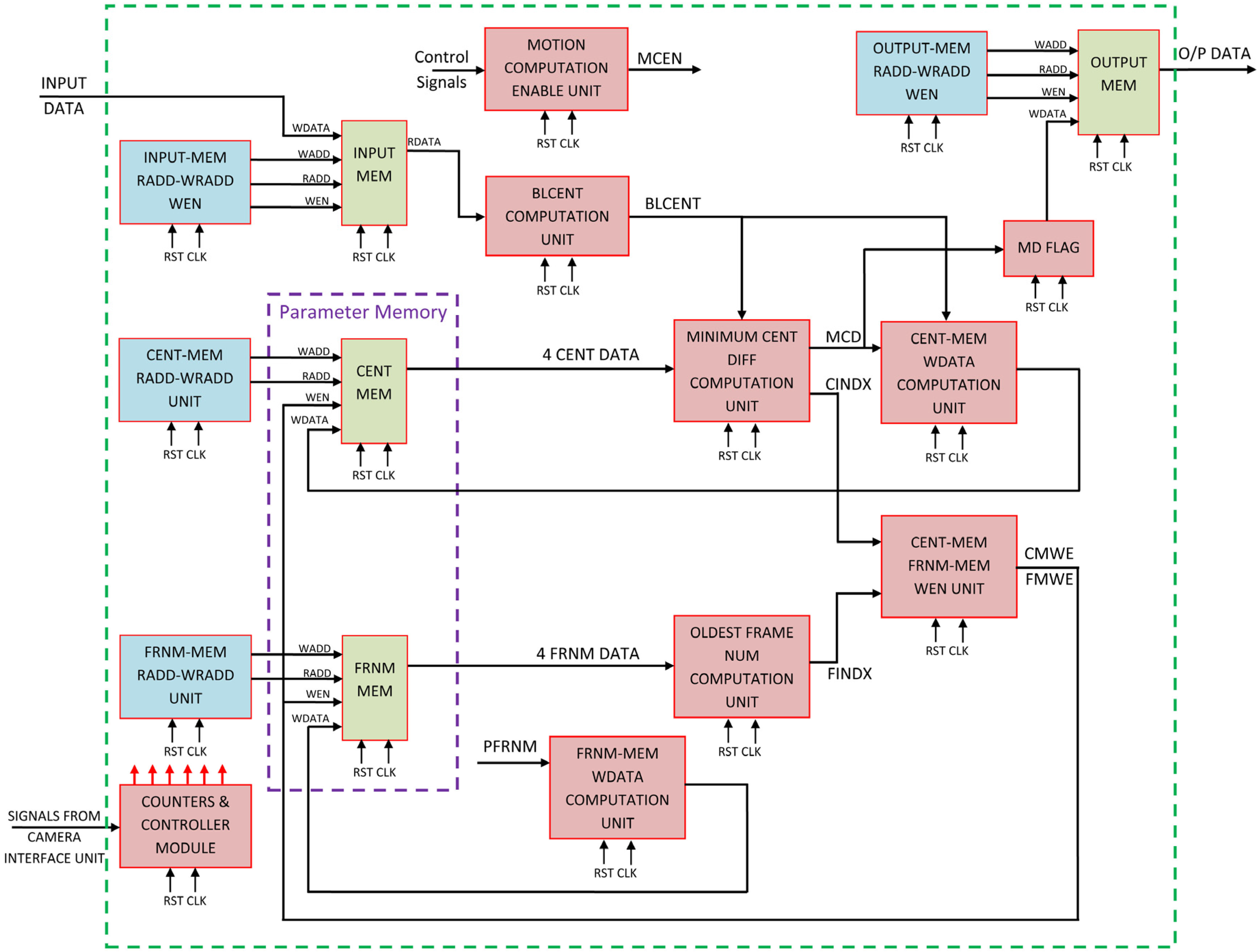
4. Proposed Architecture

In order to achieve real-time performance, as required in an automated video surveillance system, we have proposed a dedicated hardware architecture for clustering-based motion detection scheme and its implementation. The detailed VLSI architecture proposed and designed for clustering-based motion detection scheme is shown in Figure 4. The first module is INPUT MEM. This module receives the incoming pixel data as input and buffers it in the memory. Buffering is required because the motion detection algorithm works on 4 × 4 pixel windows. The output from INPUT MEM is four pixel data coming out in parallel. BLCENT COMPUTATION UNIT computes the average centroid for 4 × 4 image block by taking pixel data from the input memory (four clock cycles are required for reading 16 pixels from the input memory buffer). This computation is done by adding 16 pixel values of current block and then dividing the sum by 16. The read address, write address, and write enable signals for input memory are generated by the corresponding INPUT-MEM RADD-WRADD WEN module.
The motion computation enable (MCEN) signal is generated by MOTION COMPUTATION ENABLE UNIT. This signal is used as the enable signal in different modules of the designed motion detection architecture.
As mentioned in the algorithm section, the clustering-based scheme stores centroid and frame number information for each 4 × 4 image block. It, therefore, requires the assignment of a unique identity (or address) to each block. This is done by using row and column counters generated by COUNTERS & CONTROLLER MODULE. This unit takes the video timing signals from camera interface module and generates the different counter values (row counter, column counter, frame number counter) and control signals required for the proper functioning of complete system.
For storing background related information in the clustering-based algorithm, a parameter memory is used. It has two components viz. Centroid Memory (CENT MEM) and Frame Number Memory (FRNM MEM). Each Centroid Memory location contains four Centroid values (corresponding to four clusters) which contain the background color and intensity related information. Each Frame Number Memory location stores four Frame Number values (corresponding to four clusters) which are used to keep the record of Centroid value updating or replacement history i.e., for the particular 4 × 4 pixel block when (at what time or for what Frame Number) the cluster Centroid value is updated or replaced. The read address and write address signals for CENT-MEM and FRNM MEM are generated by the corresponding units CENT-MEM RADD-WRADD UNIT and FRNM-MEM RADD-WRADD UNIT.
During initial four frames, control signals are generated in such a way that the four clusters are initialized (one in each frame). For all subsequent frames, the generated control signals enable the motion detection process. After initialization, the matching cluster is searched within the cluster group of four clusters. For this purpose, first difference between cluster Centroid value (CENT DATA) and incoming current block Centroid value (BLCENT) is computed for all four clusters by reading the cluster Centroid values (4 CENT DATA) from CENT-MEM corresponding to current 4×4 image block and taking absolute sum of differences with current block Centroid value (BLCENT). From the four difference values, minimum Centroid difference value is selected. This complete task is carried out by the MINIMUM CENT DIFF COMPUTATION UNIT. It outputs MCD (minimum centroid difference value) and CINDX (Centroid Index). CINDX gives the cluster number corresponding to MCD (minimum centroid difference value).
In parallel with this, MINIMUM FRAME NUM COMPUTATION UNIT finds the frame index (FINDX). FINDX gives the cluster number having minimum frame number value corresponding to current 4 × 4 block in the frame number memory (FRNM MEM).
The MCD and BLCENT values are used by CENT-MEM WDATA COMPUTATION UNIT to compute the write data for Centroid Memory (CENT MEM). MCD is compared with a user defined threshold. For MCD less than or equal to the threshold (i.e., matching cluster is found), the write data for CENT MEM is the average value of current block Centroid value (BLCENT) and matching cluster Centroid value (matching cluster number is given be CINDX). For MCD greater than threshold (i.e., no matching cluster is found), the write data for CENT MEM is current block Centroid value (BLCENT) and, in this case, the cluster number for which value is replaced is determined by frame number index value (FINDX) which corresponds to the oldest cluster in the cluster group.
The write data for frame number memory (FRNM-MEM) is generated by FRNM-MEM WDATA COMPUTATION UNIT and it is the present or the current frame number (PFRNM) value.
The CINDX and FINDX values are used by CENT-MEM FRNM-MEM WEN UNIT for generating the write enable signals for CENT MEM and FRNM MEM. The write enable signals help for selecting the cluster for which the centroid value and the frame number value is to be updated or replaced.
The MD FLAG takes MCD as input and compares it with a user defined threshold. A 1-bit Flag signal is generated which is low if difference is less than the threshold (i.e., current block matches with background model and therefore, no motion is detected) and high if the difference is greater than the threshold (i.e., current block is motion detected block). This motion information data of 4x4 pixel block is written to the output memory (OUTPUT MEM) and corresponding addresses for this memory are generated by OUTPUT-MEM RADD-WRADD WEN module. Finally, the motion detected data is read from this output buffer memory and sent to the display controller for display on the screen.
The details of individual blocks of the proposed and implemented motion detection architecture are presented in the following sub-sections.

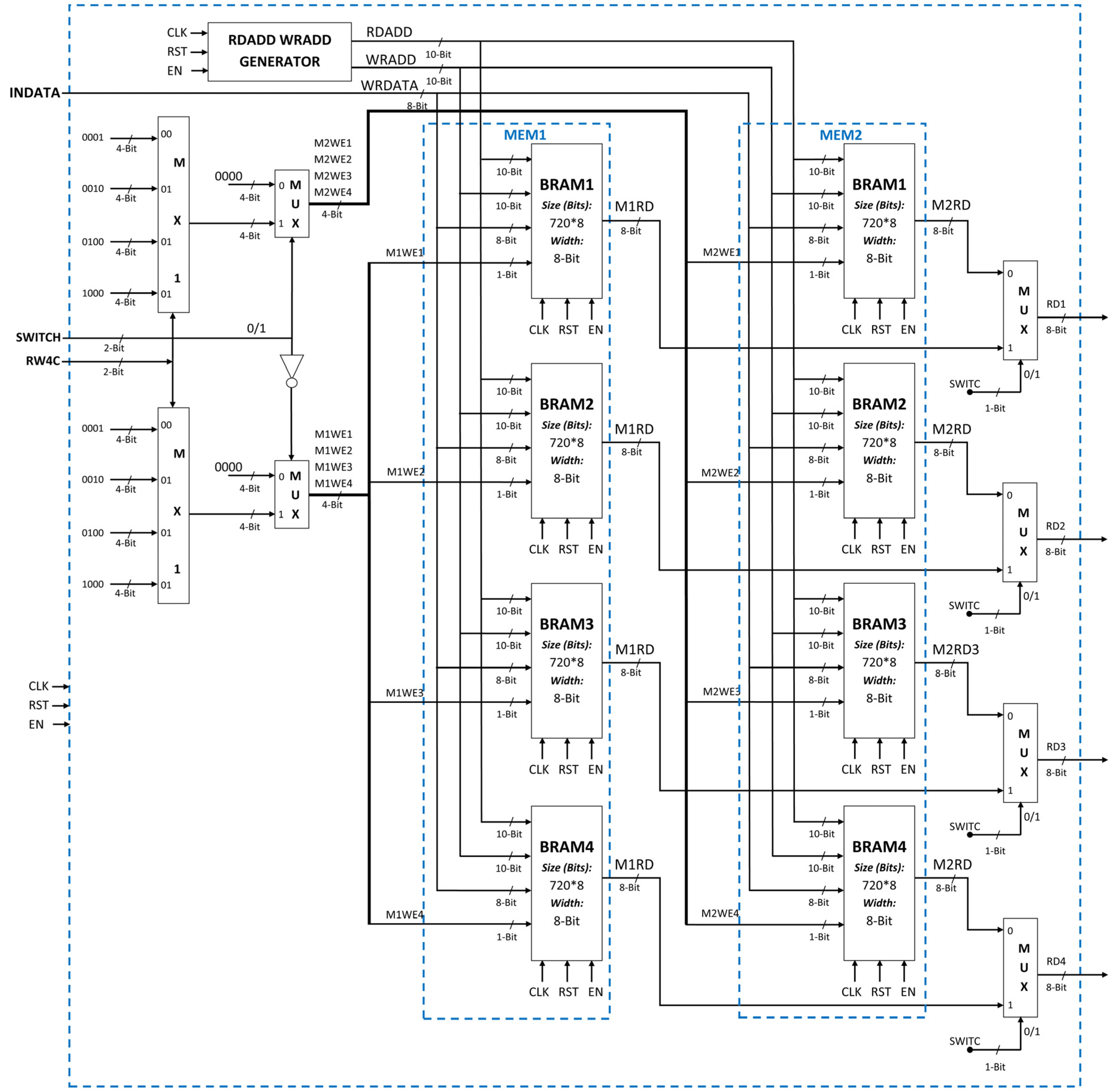
4.1. Input Buffer Memory

The input buffer memory module (Figure 5) is used to buffer the four rows of input image data. There are two memories (MEM1 and MEM2) in parallel. If the data is written in first memory then the reading is performed from the second memory and vice-versa. Each of the memory is constructed by four block RAMs (BRAMs) in FPGA. These four block RAMs are connected in parallel. Each block RAM is used to buffer one row of image pixel data. The width of each block RAM is 8-bit. The 8-bit input data is applied to the inputs of all block RAMs of MEM1 and MEM2. The read address and write address for the block RAMs of MEM1 and MEM2 are generated by RDADD WRADD GENERATOR. The write enable signals are generated separately based on the row counter (RW4C) and switch value. The selection of four output pixels (read from MEM1 or MEM2) is done by using multiplexers based on switch value.

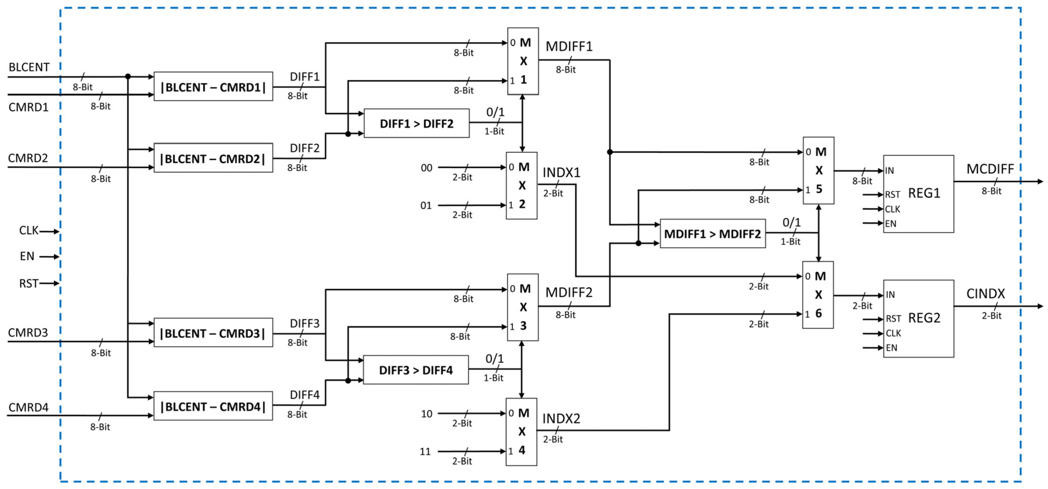
4.2. Minimum Centroid Difference Computation

The objective of this block (Figure 6) is to find the minimum centroid difference and corresponding index value. The current block centroid value is subtracted from centroid values of four clusters (read from CENT MEM). The four centroid values from CENT MEM are CMRD1, CMRD2, CMRD3, and CMRD4. The absolute difference of current block centroid BLCENT is computed in parallel with these four values. The first two differences are compared and the minimum difference among two (MDIFF1) is computed using comparator and multiplexer. The corresponding index value is also computed (INDX1). Similarly, the last two differences are compared and the minimum difference among the last two differences (MDIFF2) and corresponding index (INDX2) is computed. Finally, using a set of comparator and two multiplexers the minimum centroid difference (MCDIFF) and the corresponding centroid index (CINDX) is computed using MDIFF1 & MDIFF2 and INDX1 & INDX2, respectively.

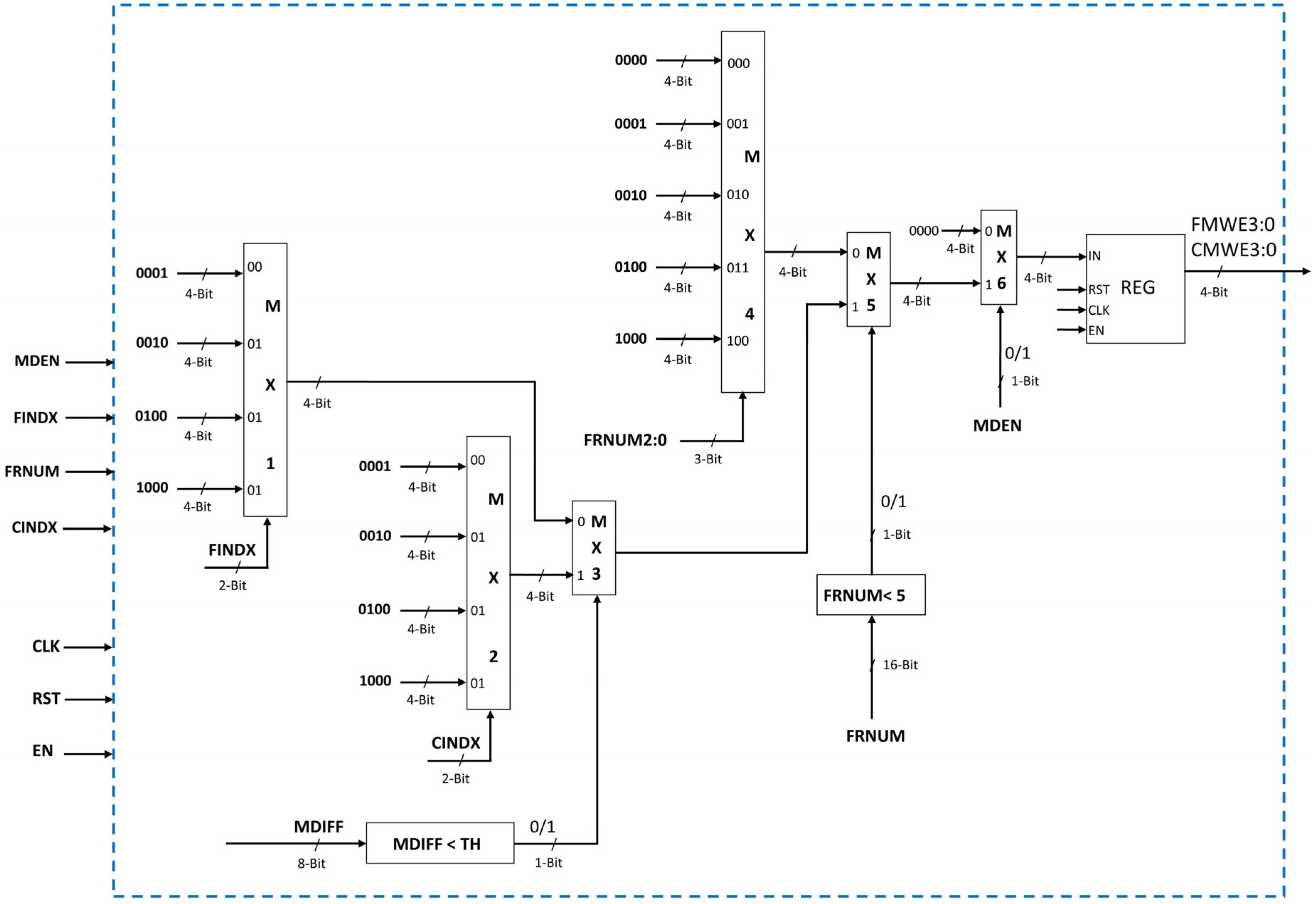
4.3. Minimum Frame Number Computation

The objective of minimum frame number computation block (Figure 7) is to find the minimum frame number and the corresponding index value. The four frame number values from FRNM MEM are FMRD1, FMRD2, FMRD3, and FMRD4. The first two frame number values (FMRD1 and FMRD2) are compared and the minimum value among two (MFN1) is computed using comparator and multiplexer. The corresponding index value is also computed (INDX1). Similarly, the last frame number values (FMRD3 and FMRD4) are compared and the minimum value among last two (MFN2) and corresponding index (INDX2) is computed. Finally, using a set of comparator and two multiplexers the minimum frame number (MFRNM) and corresponding frame number index (FINDX) is computed using MFN1 & MFN2 and INDX1 & INDX2, respectively.

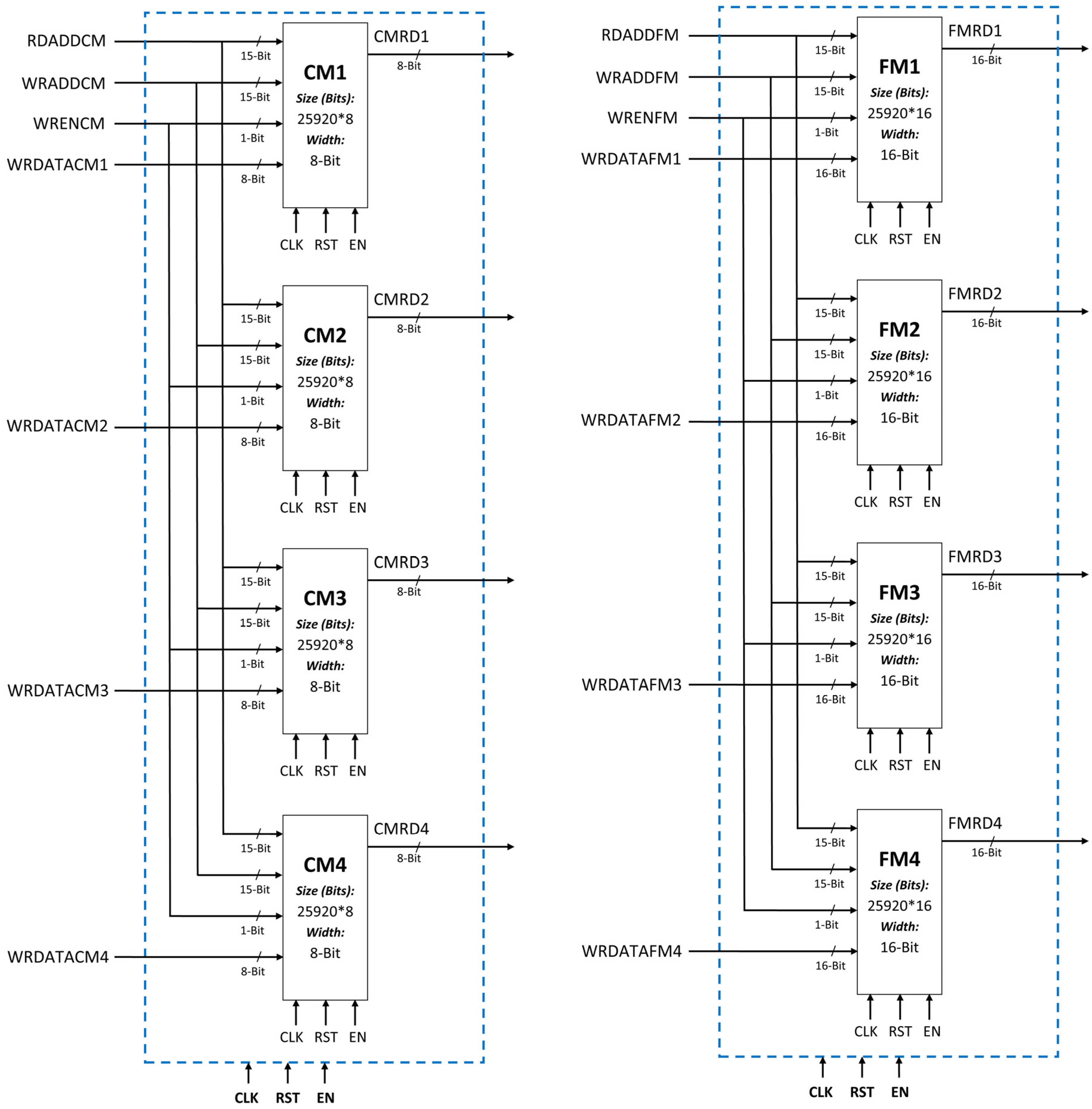
4.4. Parameter Memory

There are two parameter memories as shown in Figure 8. The first one is CENT MEM which stores centroid value of each block for four clusters. This memory contains four memory modules in parallel each corresponding to one cluster. Each centroid memory module is 8-bit wide and is 25,920 locations in size. The four centroid parameter memory modules are CM1, CM2, CM3, and CM4. The data is written to and read from all the four memories from same locations at a time. Therefore, the read address and writes address is common to all centroid memories modules. The write data (WRDATACM) and write enable signals (WRENCM) for these four memories are different. The second parameter memory is FRNM MEM which stores frame number value of each block for four clusters. This memory contains four memory modules in parallel each corresponding to one cluster. Each frame number memory module is 16-bit wide and 25,920 locations in size. The four frame number parameter memory modules are FM1, FM2, FM3, and FM4. The data is written to and read from all the four memories from same locations at a time. Therefore, the read address and writes address is common to all frame number memories modules. The write data (WRDATAFM) and write enable signals (WRENFM) for these four memories are different. The four data can be written to and read from the parameter memories at any time in single clock cycle. The data to be written to CENT MEM and FRNM MEM is computed by corresponding write data generation modules.
The write enable signals for CENT MEM and FRNM MEM are same. Therefore, a common 4-bit write enable signals is generated for both memories. Each bit of the write enable signal is corresponding to each memory module of the two parameter memories.
The 4-bit write enable signal (Figure 9) is generated based on Frame Number value, centroid index value (CINDX), frame number index (FINDX) value, and Minimum Difference Value (MDIFF). If frame number is less than 5 then write enable signal is generated in such a way that it initializes the four memories. If MDIFF is less than that of user defined threshold then, the write enable signal is generated for updating the existing centroid values and frame number values. If the MDIFF is greater than that of user defined threshold then, the write signal is generated by replacing the existing centroid and fame number values in parameter memories. This is done with the help of multiplexers and comparators.

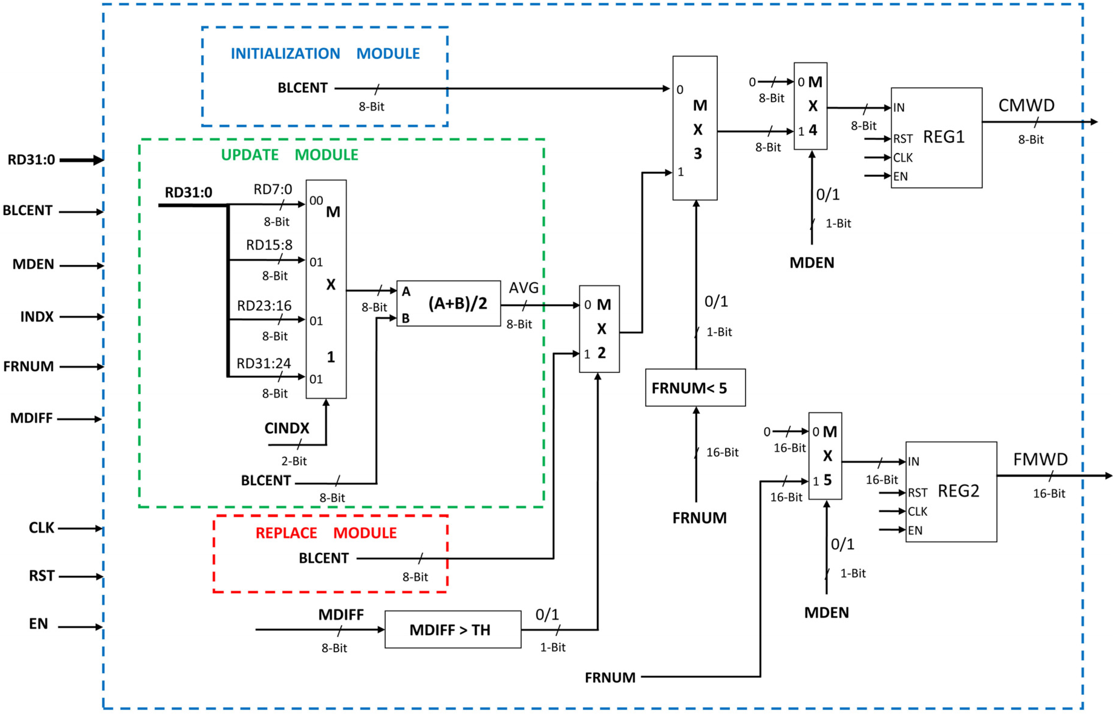
4.5. Initialize-Update-Replace Module

The objective of this block (Figure 10) is to find the minimum centroid difference and corresponding index value. The current block centroid value is subtracted from centroid values of four clusters (read from CENT MEM). Initialization-update-replace module (Figure 10) computes the data to be written in parameter memories (CENT MEM and FRNM MEM). The write data for frame number parameter memory (FMWD) is always current/present frame number (PFRNUM). It is 16-bit data and is written only when MDEN is high, otherwise it will be zero. For initial four frames, the initialization process take place, therefore the data written to centroid memory (CMWD) will be current block average centroid value (BLCENT) for initial four frames. For all subsequent frames, there are two possibilities. Either existing data will be updated or it will be replaced depending upon the value of MDIFF. If MDIFF value is greater than the user defined threshold, then replacing will take place and the old value will be replaced by current block average centroid value. If MDIFF value is less than the user defined threshold then, updating process will take place. The existing centroid value is updated with the average sum of old value of centroid and current block average centroid value. Which memory centroid is updated depends on the CINDX value. Based on CINDX, the 8-bit centroid value is selected and added with BLCENT and the result is then divided by 2 using right shift. This average value will be written to centroid parameter memory.

5. Synthesis Results

All design modules of proposed architecture for clustering based motion detection scheme have been coded in VHDL, simulated using ModelSim, and synthesized using the Xilinx ISE (Version 12.1) tool chain. The resulting configuration (bit) file was stored in the Flash Memory to enable automatic configuration of the FPGA at power-on. Thus a complete standalone prototype system for real-time motion detection has been developed and is shown in Figure 11. The components of the system are a Xilinx ML510 (Virtex-5 FX130T) FPGA platform, a Sony EVI D-70P Camera, and a display monitor.
The FPGA resources utilized (post-place & route results) by camera interface (CI), display interface (DVI), proposed architecture (PA), and complete implemented motion detection system (camera interface, proposed architecture for motion detection, and display interface) are given in Table 1. For PAL (720 × 576) resolution color video processing, implementation of the complete clustering-based motion detection system utilizes approximately 57% of the available Block RAMs on Xilinx ML510 (Virtex-5 FX130T) FPGA platform. The total power consumption (analyzed using Xilinx XPower Analyzer tool) is 1.97 W (Quiescent Power 1.82 W + Dynamic Power 0.15W). The maximum operating frequency is 73.88 MHz and maximum possible frame rate for PAL (720 × 576) size color video is 178 frames per second (fps). Frame rate achieved through the hardware implementation is far higher than that required for real-time processing and is far higher than that obtained for software implementation on a workstation.
Performance of the proposed, designed, and implemented motion detection architecture is compared with some recently published motion detection implementations using different algorithms. The performance comparison is shown in Table 2. The motion detection/segmentation architectures presented by Genovese et al. [32] and Genovese and Napoli [33] were designed for OpenCV GMM algorithm and were implemented on Virtex5 (xc5vlx50-2ff1153) FPGA. For accurate performance comparison with their work, the proposed motion detection architecture has also been synthesized (including place & route) for Virtex5 (xc5vls50) FPGA devices using Xilinx ISE tool chain.
The architecture proposed in this paper for motion detection outperforms existing implementations in terms of processing speed. An apple to apple comparison of FPGA resource utilization does not make proper sense as the motion detection algorithms used, number of background models considered, and the video formats and sizes considered in these implementations are different than in our implementation. For this reason, one to one FPGA resource utilization comparisons are not tabulated here. The system architecture for motion detection, proposed, designed, and implemented by us is adaptable and scalable for different video sizes. The proposed architecture is capable of processing HD (1920 × 1080) resolution videos in real-time at a frame rate of 35 fps.

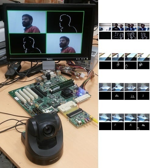
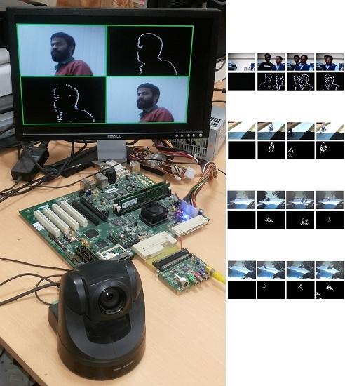
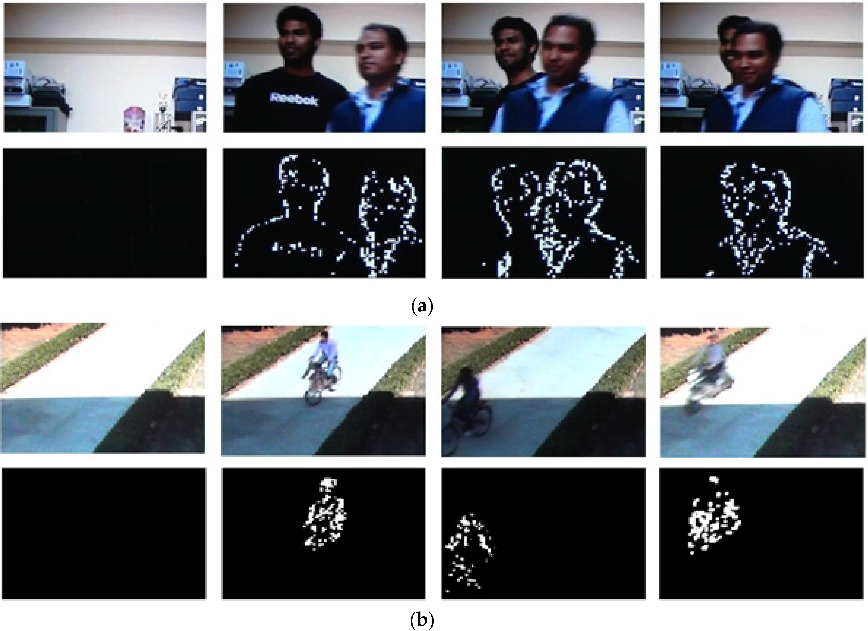
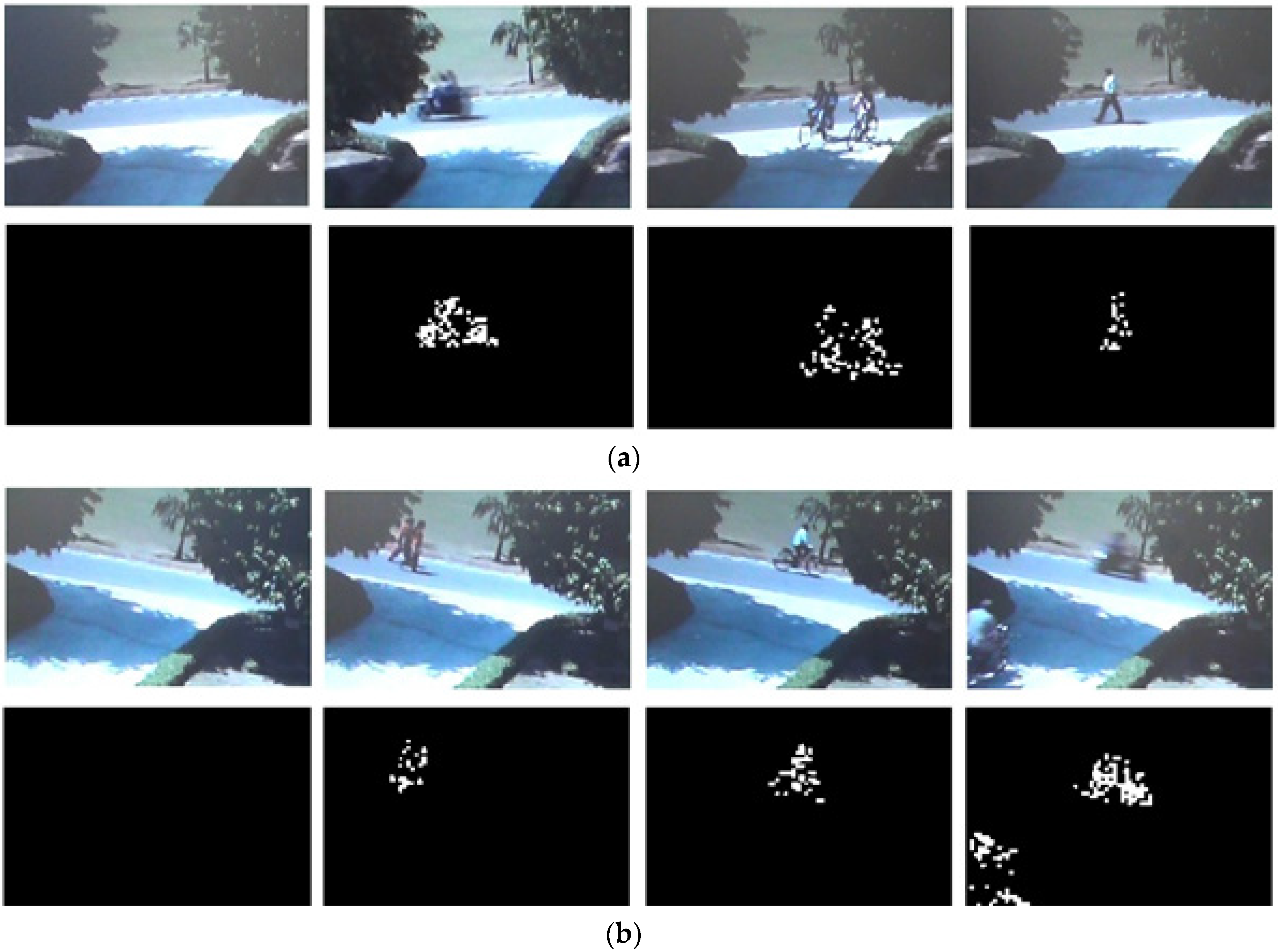
6. Motion Detection Results

The implemented system was tested for different real-world scenarios (both indoor and outdoor), which are broadly classified into two categories i.e., static background situations and pseudo-stationary background situations. Figure 12 shows examples of real-world situations of static background scenarios captured by the camera. In both the cases of Figure 12, the background is static and the moving objects are present in the scene. Motion detected by our implementation in different frames is shown just below the respective images. It can be clearly seen that only moving objects have been detected by the implemented motion detection system. Figure 13 shows the scenarios of pseudo-stationary background with moving foreground objects. In this case, there are moving leaves of the trees in the background. Despite these pseudo-stationary movements in background, only moving objects in the foreground have detected and the movements of leaves of trees in the background (irrelevant motion) have been eliminated. Results of the tests show that the system is robust enough to detect only the relevant motion in a live video scene and eliminates the continuous unwanted movements in the background itself. All the above color frames are of PAL (720 × 576) size and are extracted from live video streams produced by the implemented system.
The quantitative analysis of the motion detection quality of proposed hardware implementation is done against the software implementation of the clustering-based motion detection algorithm by using video streams of different real-world scenarios. For this purpose, for every frame of each video stream, the mean square error (MSE) is calculated. MSE is a common measure of quality of video and is equivalent to other commonly used measures of quality. For example, the peak signal-to-noise ratio (PSNR) is equivalent to MSE [34]. Some researchers measure the number of false positives (FP) and false negatives (FN) whose sum is equivalent to the MSE [54]. MSE is defined as
M S E = 1 M * N m = 0 M 1 n = 0 N 1 ( I S O F T W A R E   ( m , n )   I H A R D W A R E   ( m , n ) ) 2
In the above equation, ISOFTWARE (m, n) is the motion detected binary output image produced by running of the software (C/C++) implementation of clustering based algorithm, while IHARDWARE (m, n) is the motion detected binary output image produced by running of the proposed hardware (VLSI) implementation of a clustering based algorithm. M is the number of rows in a video frame and N is the number of columns in a video frame. The computed MSE for every frame of all the test videos is zero and it confirms that the proposed hardware (VLSI) implementation produces the same motion detection results as the software implementation of the clustering based motion detection scheme but at much higher frame rates.

7. Conclusions

In this research article, the hardware architecture for a clustering based motion detection scheme, realized using VHDL and implemented on a Xilinx ML510 FPGA platform, has been presented. The complete working prototype system, including camera interface, motion detection VLSI architecture, and display interface has been implemented on Xilinx ML510 (Virtex-5 FX130T) FPGA Board. The implemented system can robustly and automatically detect relevant motion in real-world scenarios (both for the static backgrounds and the pseudo-stationary backgrounds) for standard PAL (720x576) resolution live incoming video streams in real-time. It can be effectively used as a standalone component for motion detection in video surveillance systems.

Acknowledgments

The financial support of Department of Electronics & Information Technology (DeitY)/Ministry of Communications and Information Technology (MCIT), the Govt. of India is gratefully acknowledged.

Author Contributions

All authors have contributed for this manuscript.

Conflicts of Interest

The authors declare no conflict of interest. The founding sponsors had no role in the design of the study; in the collection, analyses, or interpretation of data; in the writing of the manuscript, and in the decision to publish the results.

References

  1. Radke, R.J.; Andra, S.; Kofahi, O.A.; Roysam, B. Image Change Detection Algorithms: A Systematic Survey. IEEE Trans. Image Process. 2005, 14, 294–307. [Google Scholar] [CrossRef] [PubMed]
  2. Rosin, P.L. Thresholding for Change Detection. In Proceedings of the Sixth International Conference on Computer Vision, Bombay, India, 4–7 January 1998; pp. 274–279.
  3. Rosin, P.L.; Ioannidis, E. Evaluation of Global Image Thresholding for Change Detection. Pattern Recognit. Lett. 2001, 24, 2345–2356. [Google Scholar] [CrossRef]
  4. Smits, P.C.; Annoni, A. Toward Specification-Driven Change Detection. IEEE Trans. Geosci. Remote Sens. 2000, 38, 1484–1488. [Google Scholar] [CrossRef]
  5. Bruzzone, L.; Prieto, D.F. Automatic Analysis of the Difference Image for Unsupervised Change Detection. IEEE Trans. Geosci. Remote Sens. 2000, 38, 1171–1182. [Google Scholar] [CrossRef]
  6. Colwell, J.E.; Weber, F.P. Forest Change Detection. In Proceedings of the 15th International Symposium on Remote Sensing of the Environment, Ann Arbor, MI, USA, 11–15 May 1981; pp. 839–852.
  7. Malila, W.A. Change Vector Analysis: An Approach for Detecting Forest Changes with Landsat. In Proceedings of the Symposium on Machine Processing of Remotely Sensed Data, West Lafayette, IN, USA, 3–6 June 1980; pp. 326–336.
  8. Singh, A. Review Article: Digital Change Detection Techniques using Remotely-sensed Data. Int. J. Remote Sens. 1989, 10, 989–1003. [Google Scholar] [CrossRef]
  9. Stefano, L.D.; Mattoccia, S.; Mola, M. A Change-detection Algorithm based on Structure and Color. In Proceedings of the IEEE Conference on Advanced Video and Signal-Based Surveillance, 21–22 July 2003; pp. 252–259.
  10. Hsu, Y.Z.; Nagel, H.H.; Rekers, G. New Likelihood Test Methods for Change Detection in Image Sequences. Comput. Vision Graph. Image Process. 1984, 26, 73–106. [Google Scholar] [CrossRef]
  11. Skifstad, K.; Jain, R. Illumination Independent Change Detection for Real World Image Sequences. Comput. Vision Graph. Image Process. 1989, 46, 387–399. [Google Scholar] [CrossRef]
  12. Elfishawy, A.S.; Kesler, S.B.; Abutaleb, A.S. Adaptive Algorithms for Change Detection in Image Sequence. Signal Process. 1991, 23, 179–191. [Google Scholar] [CrossRef]
  13. Jain, Z.S.; Chau, Y.A. Optimum Multisensor Data Fusion for Image Change Detection. IEEE Trans. Syst. Man Cybern. 1995, 25, 1340–1347. [Google Scholar] [CrossRef]
  14. Toyama, K.; Krumm, J.; Brumitt, B.; Meyers, B. Wallflower: Principles and Practice of Background Maintenance. In Proceedings of the Seventh International Conference on Computer Vision, Kerkyra, Greece, 20–27 September 1999; pp. 255–261.
  15. Clifton, C. Change Detection in Overhead Imagery using Neural Networks. Appl. Intell. 2003, 18, 215–234. [Google Scholar] [CrossRef]
  16. Durucan, E.; Ebrahimi, T. Change Detection and Background Extraction by Linear Algebra. In Proceedings of the IEEE, October 2001; Volume 89, pp. 1368–1381. [CrossRef]
  17. Li, L.; Leung, M.K.H. Integrating Intensity and Texture Differences for Robust Change Detection. IEEE Trans. Image Process. 2002, 11, 105–112. [Google Scholar] [PubMed]
  18. Liu, S.C.; Fu, C.W.; Chang, S. Statistical Change Detection with Moments under Time-Varying Illumination. IEEE Trans. Image Process. 1998, 7, 1258–1268. [Google Scholar] [PubMed]
  19. Cavallaro, A.; Ebrahimi, T. Video Object Extraction based on Adaptive Background and Statistical Change Detection. In Proceedings of the SPIE Visual Communications and Image Processing, San Jose, CA, USA, 20 January 2001; pp. 465–475.
  20. Huwer, S.; Niemann, H. Adaptive Change Detection for Real-Time Surveillance Applications. In Proceedings of the Third IEEE International Workshop on Visual Surveillance, Dublin, Ireland, 1 July 2000; pp. 37–46.
  21. Kanade, T.; Collins, R.T.; Lipton, A.J.; Burt, P.; Wixson, L. Advances in Cooperative Multi-Sensor Video Surveillance. In Proceedings of the DARPA Image Understanding Workshop, San Francisco, USA, 20 November 1998; pp. 3–24.
  22. Stauffer, C.; Grimson, W.E.L. Learning Patterns of Activity using Real-Time Tracking. IEEE Trans. Pattern Anal. Mach. Intell. 2000, 22, 747–757. [Google Scholar] [CrossRef]
  23. Butler, D.E.; Bove, V.M.; Sridharan, S. Real-Time Adaptive Foreground/Background Segmentation. EURASIP J. Appl. Signal Process. 2005, 2005, 2292–2304. [Google Scholar] [CrossRef] [Green Version]
  24. Dumontier, C.; Luthon, F.; Charras, J.P. Real-Time Implementation of An MRF-based Motion Detection Algorithm on a DSP Board. In Proceedings of the IEEE Workshop on Digital Signal Processing, Leon, 1–4 September 1996; pp. 183–186.
  25. Dumontier, C.; Luthon, F.; Charras, J.P. Real-Time DSP Implementation for MRF-based Video Motion Detection. IEEE Trans. Image Process. 1999, 8, 1341–1347. [Google Scholar] [CrossRef] [PubMed]
  26. Bassignana, P.; Martina, M.; Masera, G.; Molino, A.; Vacca, F. DSP Implementation of a Low Complexity Motion Detection Algorithm. In Proceedings of the 39th Asilomar Conference on Signals, Systems and Computers, Pacific Groove, USA, 28 October–1 November 2005; pp. 1352–1355.
  27. Benkhalil, A.K.; Lpson, S.S.; Booth, W. A Novel CPLD based Implementation of a Motion Detection Algorithm for Surveillance Applications. In Proceedings of the International Conference on Custom Integrated Circuits, Santa Clara, CA, USA, 11–14 May 1998; pp. 105–108.
  28. Liu, Z.; Li, Z.; Li, G.; Zhang, X.; Zhang, H. A Novel Motion-Detection and Edge Detection Algorithm Based on Motion Estimation. In Recent Advances in Computer and Information Engineering; Springer: Berlin, Heidelberg, 2012; Volume 128, pp. 295–308. [Google Scholar]
  29. Luthon, F.; Dragomirescu, D. A Cellular Analog Network for MRF Based Video Motion Detection. IEEE Trans. Circuits Syst. I 1999, 46, 281–293. [Google Scholar] [CrossRef]
  30. Kristensen, F.; Hedberg, H.; Jiang, H.; Nilsson, P.; Öwall, V. An Embedded Real-Time Surveillance System: Implementation and Evaluation. J. Signal Process. Syst. 2008, 52, 75–94. [Google Scholar] [CrossRef]
  31. Jiang, H.; Ardö, H.; Öwall, V. A Hardware Architecture for Real-time Video Segmentation Utilizing Memory Reduction Techniques. IEEE Trans. Circuits Syst. Video Technol. 2009, 19, 226–236. [Google Scholar] [CrossRef]
  32. Genovese, M.; Napoli, E.; Petra, N. OpenCV Compatible Real Time Processor for Background Foreground Identification. In Proceedings of the International Conference on Microelectronics, Cairo, Egypt, 19–22 December 2010; pp. 467–470.
  33. Genovese, M.; Napoli, E. FPGA-Based Architecture for Real Time Segmentation and Denoising of HD Video. J. Real Time Image Process. 2013, 8, 389–401. [Google Scholar] [CrossRef]
  34. Genovese, M.; Napoli, E. ASIC and FPGA Implementation of the Gaussian Mixture Model Algorithm for Real-time Segmentation of High Definition Video. IEEE Trans. Very Large Scale Integr. 2014, 22, 537–547. [Google Scholar] [CrossRef]
  35. Yu, N.; Kim, K.; Salcic, Z. A New Motion Estimation Algorithm for Mobile Real-Time Video and Its FPGA Implementation. In Proceedings of the IEEE Region 10 Conference TENCON, Thailand, 21–24 November 2004; pp. 383–386.
  36. Saad, E.M.; Hamdy, A.; Abutaleb, M.M. Reconfigurable Hardware Implementation of a Fast and Efficient Motion Detection Algorithm. In Proceedings of the 10th International Conference on Mathematical Methods and Computational Techniques in Electrical Engineering, Corfu Island, Greece, 26–28 October 2008; pp. 40–45.
  37. Zhang, T.; Wu, H.; Borst, A.; Kuhnlenz, K.; Buss, M. An FPGA Implementation of Insect-Inspired Motion Detector for High-Speed Vision Systems. In Proceedings of the International Conference on Robotics and Automation, Pasadena, CA, USA, 19–23 May 2008; pp. 335–340.
  38. Hussian, S.N.; Rao, K.S.; Ashfaq, S.M. The Hardware Implementation of Motion Object Detection Based on Background Subtraction. Int. J. Adv. Res. Comput. Sci. Softw. Eng. 2013, 3, 1297–1302. [Google Scholar]
  39. Liang, H.; Morie, T. A Motion Detection Model Inspired by Hippocampal Function and Its FPGA Implementation. In Proceedings of the International Conference on Neural Information Processing, Shanghai, China, 13–17 November 2011; Volume 7064, pp. 522–529.
  40. McErlean, M. Hierarchical Motion Estimation for Embedded Object Tracking. In Proceedings of the IEEE International Symposium on Signal Processing and Information Technology, Vancouver, BC, Canada, 27–30 August 2006; pp. 797–802.
  41. Sanchez-Ferreira, C.; Mori, J.Y.; Llanos, C.H. Background Subtraction Algorithm for Moving Object Detection in FPGA. In Proceedings of the Southern Conference on Programmable Logic, Bento Goncalves, Brazil, 20–23 March 2012; pp. 1–6.
  42. Bing, X.; Charoensak, C. Rapid FPGA Prototyping of Gabor-Wavelet Transform for Applications in Motion Detection. In Proceedings of the 7th International Conference on Control, Automation, Robotics and Vision, Singapore, 2–5 December 2002; Volume 3, pp. 1653–1657.
  43. Desmouliers, C.; Oruklu, E.; Sanile, J. FPGA-Based Design of a High-Performance and Modular Video Processing Platform. In Proceedings of the International Conference on Electro/Information Technology, Windsor, ON, Canada, 7–9 June 2009; pp. 393–398.
  44. Singh, S.; Mandal, A.S.; Shekhar, C.; Vohra, A. Real-time Implementation of Change Detection for Automated Video Surveillance System. ISRN Electron. 2013, 2013. Article ID 691930. [Google Scholar] [CrossRef]
  45. Singh, S.; Dunga, S.M.; Saini, R.; Mandal, A.S.; Shekhar, C.; Vohra, A.; Chaudhary, S. Hardware Accelerator Design for Change Detection in Smart Camera. In Proceedings of the SPIE International Conference on Graphics and Image Processing (ICGIP 2011), Cairo, Egypt, 30 September 2011.
  46. Bartosinski, R.; Danek, M.; Sykora, J.; Kohout, L.; Honzik, P. Video Surveillance Application Based on Application Specific Vector Processors. In Proceedings of the International Conference on Design and Architecture for signal and Image Processing, Karlsruhe, Germany, 23–25 October 2012; pp. 1–8.
  47. Saad, E.M.; Hamdy, A.; Abutateb, M.M. FPGA Implementation of a Low Cost and Area Real-Time Motion Detection. In Proceedings of the 15th International Conference on Mixed Design of Integrated Circuits and Systems, Poznan, Poland, 19–21 June 2008; pp. 249–254.
  48. Chowdary, M.K.; Babu, S.S.; Babu, S.S.; Khan, H. FPGA Implementation of Moving Object Detection in Frames by Using Background Subtraction Algorithm. In Proceedings of the International Conference on Communication and Signal Processing, Melmaruvathur, India, 3–5 April 2013; pp. 1032–1036.
  49. Hao, J.; Shibata, T. A VLSI-Implementation-Friendly EGO-Motion Detection Algorithm Based on Edge-Histogram Matching. In Proceedings of the International Conference on Acoustics, Speech and Signal Processing, Toulouse, 14–19 May 2006; Volume 2, pp. 245–248.
  50. Singh, S.; Dunga, S.M.; Mandal, A.S.; Shekhar, C.; Chaudhary, S. FPGA based Embedded Implementation of Video Summary Generation Scheme in Smart Camera Systems. Adv. Mater. Res. 2011, 403–408, 516–521. [Google Scholar] [CrossRef]
  51. Singh, S.; Dunga, S.M.; Mandal, A.S.; Chaudhary, S. Embedded Implementation of Change Detection Algorithm for Smart Camera Systems. In Proceedings of the IEEE International Conference on Recent Trends in Information, Telecommunication, and Computing, Kochi, Kerala, 12–13 March 2010; pp. 268–270.
  52. Singh, S.; Saini, R.; Saini, A.K.; Mandal, A.S.; Shekhar, C. Performance Evaluation of Different Memory Components for FPGA based Embedded System Design for Video Processing Application; International Journal of Intelligent Systems and Applications (IJISA), MECS Press: Hong Kong, China, 2013; Volume 5, pp. 113–119. [Google Scholar]
  53. Chutani, E.R.; Chaudhury, S. Video Trans-Coding in Smart Camera for Ubiquitous Multimedia Environment. In Proceedings of the International Symposium on Ubiquitous Multimedia Computing, Hobart, Australia, 13–15 October 2008; pp. 185–189.
  54. Rodriguez-Gomez, R.; Fernandez-Sanchez, E.J.; Diaz, J.; Ros, E. FPGA Implementation for Real-Time Background Subtraction Based on Horprasert Model. Sensors 2012, 12, 585–611. [Google Scholar] [CrossRef] [PubMed]
Figure 1. Clustering-Based Motion Detection Scheme.
Electronics 05 00010 g001
Figure 2. Pseudo-code for Clustering-based Motion Detection Scheme.
Electronics 05 00010 g002
Figure 3. Dataflow Diagram of the Proposed and Developed Motion Detection System.
Electronics 05 00010 g003
Figure 4. Proposed & Implemented VLSI Architecture for Clustering-based Motion Detection Scheme.
Electronics 05 00010 g004
Figure 5. Proposed VLSI architecture for Input Buffer Memory.
Electronics 05 00010 g005
Figure 6. Proposed VLSI architecture of Minimum Centroid Difference Computation Module.
Electronics 05 00010 g006
Figure 7. Proposed VLSI architecture of Minimum Frame Number Computation Module.
Electronics 05 00010 g007
Figure 8. Parameter Memory (Centroid and Frame Number) of Motion Detection Architecture.
Electronics 05 00010 g008
Figure 9. Parameter Memory (Centroid and Frame Number) Write Enable Signal Generation.
Electronics 05 00010 g009
Figure 10. Proposed VLSI architecture of Initialization, Update, and Replace Module.
Electronics 05 00010 g010
Figure 11. Complete Motion Detection System Setup.
Electronics 05 00010 g011
Figure 12. Moving Objects in Video Scene and Corresponding Motion Detected Outputs for Static Background Scenarios.
Electronics 05 00010 g012
Figure 13. Moving Objects in Video Scene and Corresponding Motion Detected Outputs for Pseudo-stationary Background Scenarios.
Electronics 05 00010 g013
Table 1. FPGA Resource Utilization by Clustering based Motion Detection System.
ResourcesCamera Interface (CI)Display (DVI)Proposed Architecture (PA)Complete System (CI + PA +DVI)Total Available ResourcesPercentage of Utilization
Slice Registers39179239701819200.86%
Slice LUTs43410113791884819202.30%
Route-thrus4239621221638400.07%
Occupied Slices19933467697208403.34%
BRAMs 36K3016817129857.38%
Memory (Kb)1080604861561072857.38%
DSP Slices30033200.94%
IOs162236368404.28%
Table 2. Performance Comparison with Existing Motion Detection Implementations.
Target FPGA DeviceImplementationMaximum Clock Frequency (MHzFrame Rate for PAL Resolution Video
Virtex5 (xc5fx130t-2ff1738)Our Implementation73.88 MHz178
Virtex5 (xc5vlx50-2ff1153)Our Implementation73.88 MHz178
[33]50.50 MHz121
[32]47.00 MHz113

