1. Introduction
The increasing energy demand and the industrial plants modernization brought together an increasing number of power-electronics devices directly connected to the medium-voltage distribution systems. Several of these devices are assembled with diodes or thyristors, which cause severe distortions on voltages and currents, degrading the power quality and causing serious problems in distribution networks. Furthermore, the semiconductors have physical limitations on voltage and current, which restrict their use in high-power, high-voltage applications. Currently, these limits are 8 kV and 6 kA [
1]. Therefore, the use of a multilevel converter helps to minimize all these issues for medium-voltage applications.
Multilevel converters present many advantages when compared with conventional two-level converters, such as capacity to operate in high-voltage levels, smaller semiconductors devices and higher number of voltage levels in the output voltage. Moreover, multilevel topology also presents a lower total harmonic distortion (THD) and allows a reduction of switching frequency [
2,
3]. Thus, the use of multilevel topologies combined with power quality conditioners, such as Static Synchronous Compensator (STATCOM) [
4,
5], can improve power quality and efficiency in distribution systems [
6].
Several multilevel topologies have been reported in the last decade [
1,
7]. The Neutral Point Clamped Converter (NPC) is the most mature technology among all available multilevel topologies [
8,
9]. There are two converter topologies that might compete with the NPC: the Flying Capacitor Converter (FC) [
10], and the Symmetric or Asymmetric Cascade H-Bridge Converter (CHB) [
11]. The symmetric CHB is one of the most promising topologies because it uses fewer components then the NPC and FC topologies for a same number of voltage level in the ac output voltage. The symmetric CHB topology can also be used in Modular Multilevel Converters (MMC) [
12]. Recently, a variation of the symmetric CHB was proposed by means of chopper-cell modules instead of H-Bridge modules [
11]. As an example, Siemens already uses a half-bridge MMC topology known as HVDC PLUS for applications up to 1,000 MW. In this context, many works have been reported dealing with comparisons between several multilevel topologies [
13,
14,
15,
16]. Although all multilevel topologies have similar performance, only the Asymmetric CHB is capable of producing the same output-voltage level with a minimum number of power semiconductors [
17,
18,
19].
In order to achieve a better performance for the multilevel converters, not only the selection of the best multilevel topology for a specific application is important, but also the selection of an efficient switching strategy related to that topology should be taken into account. Several studies have contributed with a variety of switching methods for each converter topology [
1,
20,
21]. Recently, the carrier-shifting modulation method was proposed, claiming to produce the optimum harmonic cancellation for a symmetric multilevel converter [
2,
22]. Another one, the phase-shifted PWM (PS‑PWM) modulation was conceived for FC and CHB converters and introduces a phase shift between the carrier signals of contiguous cells. Different from PS-PWM, the level-shifted PWM (LS‑PWM) is a method where carries are arranged in vertical shifts. Variations in the carriers arrangement results in different switching techniques, like the phase disposition PWM (PD-PWM), the phase opposition disposition PWM (POD-PWM), and the alternate phase opposition PWM (APOD‑PWM). All those techniques are mainly applied to the symmetric multilevel converter and the NPC converter. For asymmetric multilevel converters, the best modulation method is the hybrid modulation [
23] that uses different frequencies for each power module. This allows a reduction in switching frequency, which leads to a reduction in the converter losses [
19,
24].
The main drawback of the Asymmetric CHB topology is the necessity of isolated and unequal dc‑link voltages, making it difficult to regulate all the isolated dc-link capacitor voltages. In fact, the different values of dc-link voltages make the use of any kind of average control almost impossible. For instance, arm-balancing control combined with an averaging control method [
25] or power-flow analysis method [
26], usually applied for Symmetric CHB topologies, must be avoid in Asymmetric CHB topologies. Other strategies using the principle of commutation technique as in [
27], or binary mode relation among dc-link voltage levels as in [
28], or even a dedicated rectifier for each separated module have been proposed. Nevertheless, these solutions do not present a general control method for dc-link voltage regulation. Instead, they are specific solutions for a particular application.
The main contribution of this work is the development of an improved hybrid modulation and a new isolated and unequal dc-link voltage control strategy for the Asymmetric CHB topology.
2. Multilevel Converter
Generally, the nominal values of the dc voltages in each power module and the maximum level of total harmonic distortion (THD) required to the output voltage define the quantity of power modules that will compose the multilevel converter. Usually, the maximum THD of the output voltage to connect directly the converter to the electrical system is a parameter to calculate the number of voltage levels.
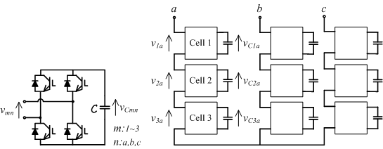
Single-phase full-bridge inverter, as shown in
Figure 1, can generate three values at the output voltage:
vmn = −
vCmn;
vmn = 0;
vmn = +
vCmn. With different values of dc voltage in each power module, the series connection of the output voltages of those modules results in a multilevel voltage. This approach is generally called as Asymmetric Cascade H-Bridge Converter. For instance, the series connection of three H-bridges as in
Figure 1 generates a nineteen-level voltage, if the dc voltages in the power modules in a leg are set as
vC1a, 2
vC1a, and 6
vC1a, respectively, for the a-phase of the converter. Since the current flowing through the power modules in a leg is the same, the nominal powers of the power modules are
S, 2
S and 6
S, respectively. The higher the number of voltage level, the lower is the total harmonic distortion (THD) of the generated output voltage of the multilevel converter.
In Brazil, two standards related to THD limits on power grid are adopted. One is an international recommendation from IEEE [
29]. The other is a national procedure from the National Electric Energy Agency (ANEEL) [
30].
Table 1 shows voltage distortion limits from IEEE and ANEEL.
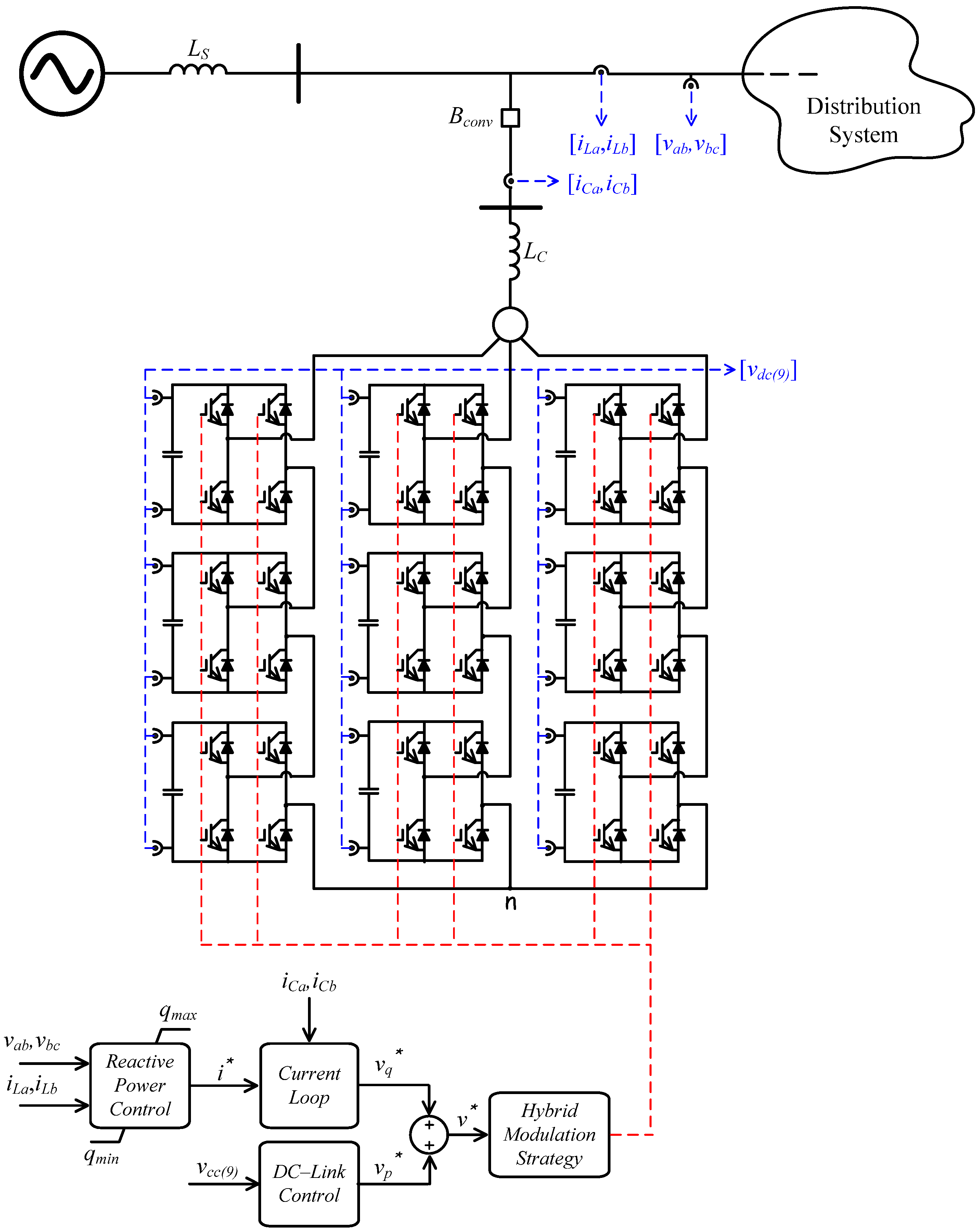
Figure 1 shows the asymmetric cascaded converter for three-phase systems with the Y-connection used to obtain experimental results. It is an asymmetrical multilevel converter that generates nineteen levels at each phase-to-neutral voltage. A critical issue of this converter topology is the regulation of all dc-capacitor voltages. An original contribution of this development is the way to perform the dc‑voltage regulation, as it will be shown in the following sections.
Figure 1.
Asymmetric cascaded converter; (a) power cell topology; (b) converter topology.
Figure 1.
Asymmetric cascaded converter; (a) power cell topology; (b) converter topology.
Table 1.
Voltage distortion limits.
Table 1.
Voltage distortion limits.
| Bus Voltage at PCC | Total Harmonic Distortion–THD |
|---|
| IEEE | ANEEL |
|---|
| V ≤ 1.0 kV | 8 | 10 |
| 1.0 kV < V ≤ 13.8 kV | 5 | 8 |
| 13.8 kV < V ≤ 69.0 kV | 5 | 6 |
3. Modulation Strategy
Multilevel converters can use many modulation strategies. Most common modulation methods are Phase Shifted (PS-PWM), a natural extension of traditional PWM techniques and specially conceived for FC and CHB converters, Level Shifted (LS-PWM), an extension of bipolar PWM for multilevel converters and Hybrid Modulation, an extension of PWM for CHB with unequal dc sources. Although the LS-PWM presents an equivalent harmonic cancelation with the PS-PWM, this modulation has a practical limitation. In the PS-PWM, a high output switching frequency is naturally achieved by combination of each low frequency carrier signals. In order to obtain the same output switching frequency, all the carrier signals of the LS-PWM has to be multiplied by the number of cells used in the multilevel structure. Equations (1) and (2) present the output switching frequency of the PS-PWM and LS-PWM where N is the number of modules used in the multilevel structure.
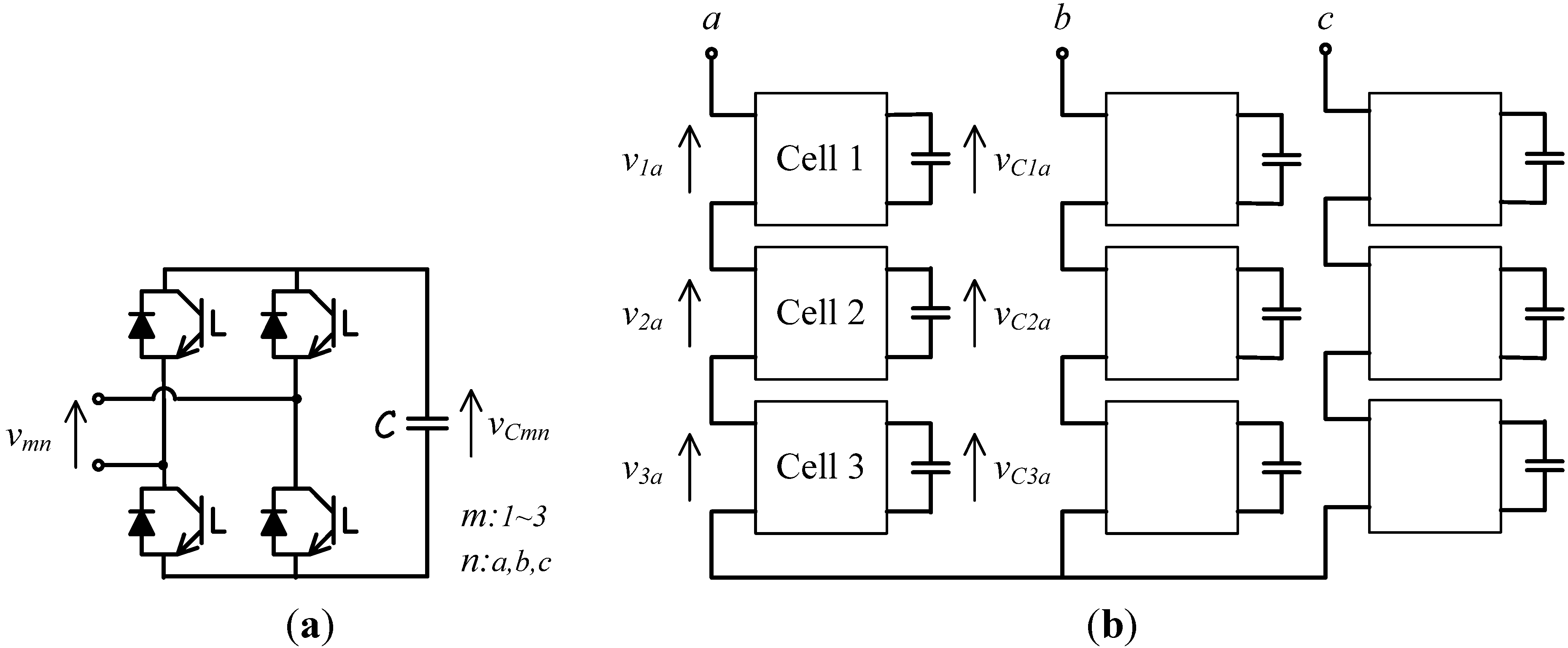
The Hybrid Modulation presents the advantage to work with only one high switching frequency module per phase, which implies a switching losses reduction. Furthermore, the output switching frequency is defined by the carrier frequency of the low power module, thus the high output switching frequency advantage is maintained. There are several patterns for creating modulation methods to multilevel converters. The principal ones are classified in
Figure 2 [
1,
22,
31].
Figure 2.
Multilevel converter modulation methods.
Figure 2.
Multilevel converter modulation methods.
By means of Hybrid Modulation type, the goal is the reduction of the switching frequency of the higher power modules to reduce the switching losses in the multilevel converter. The idea is to combine the staircase modulation for the high and medium power modules with the PWM modulation for the low power module, as presented in [
1,
22,
31]. An enhanced Hybrid Modulation was proposed by the authors in [
3,
32], which results in a lower line-to-line THD output voltage without increase of the switching frequency or losses. As presented in previous works, the enhanced Hybrid Modulation can mitigate up to 40% of the line-to-neutral THD voltage, while the conventional Hybrid Modulation can mitigate only 15% of the line-to-neutral THD voltage.
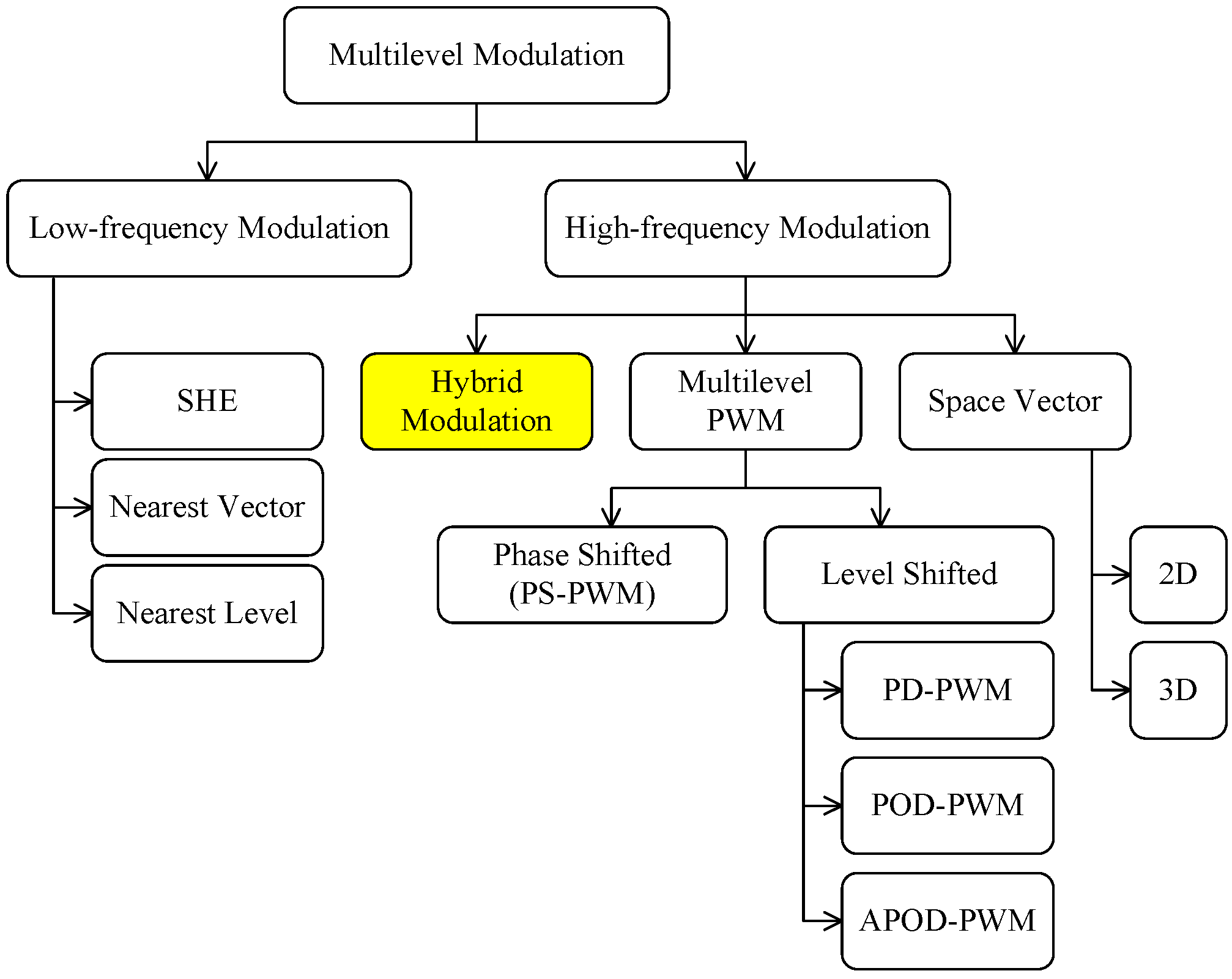
Figure 3 illustrates the switching method adopted in this work. DC–link voltages of
vdc,
2vdc and
6vdc are selected to produce equal voltage steps in the generated nineteen-level output voltage [
33].
Figure 3.
Multilevel modulation strategy; (a) cell 1 output voltage; (b) cell 2 output voltage; (c) cell 3 output voltage; (d) converter output voltage.
Figure 3.
Multilevel modulation strategy; (a) cell 1 output voltage; (b) cell 2 output voltage; (c) cell 3 output voltage; (d) converter output voltage.
4. Control Circuits
4.1. Reactive-Power Control
The reactive-power control is very important in distribution systems. The surplus of reactive power increases the total current flowing through the feeder directly influencing the distribution losses, voltage control, investments and utility tariff. The distribution losses that occur through heat dissipation are proportional to the square of the feeder current. The excess of reactive power increases the electrical current, establishes a direct relationship between distribution losses and low power factor and leads a raise in temperature of conductors and equipment. Therefore, the distribution losses are reduced indirectly by controlling the feeder’s reactive power. The increase of the currents due to excess reactive power also leads to large voltage drops and may cause the interruption of electricity supply and overloads in certain network elements as motors. The risk of an interruption is accentuated mainly during heavy load scenarios, when the demand of energy in distribution system is higher. In this case, the reactive power control promotes a reduction of the feeder’s current, decreasing the voltage drops. The power factor compensation also raises the distribution capacity by releasing load especially in feeders and transformers. As a result, investments that would be needed to expand the distribution system can be postponed. In this context, multilevel converter takes an opportunity to show how they can support the medium voltage distribution systems, promoting loss reduction, voltage control, postponing investments and the maintenance of the utility tariff, just controlling the reactive power.
The power and control circuits of the multilevel D–STATCOM are presented in
Figure 4. The line voltages and currents measured in the feeder are
,
,
and
and the currents measured in the converter are
and
. All capacitor voltages are measured and used in the controller of the multilevel converter. The D–STATCOM is designed to compensate the power factor of the feeder in real time, by injecting variable reactive power in the distribution system in order to maintain a unity power factor reference. The controller uses the concepts of instantaneous power theory [
34].
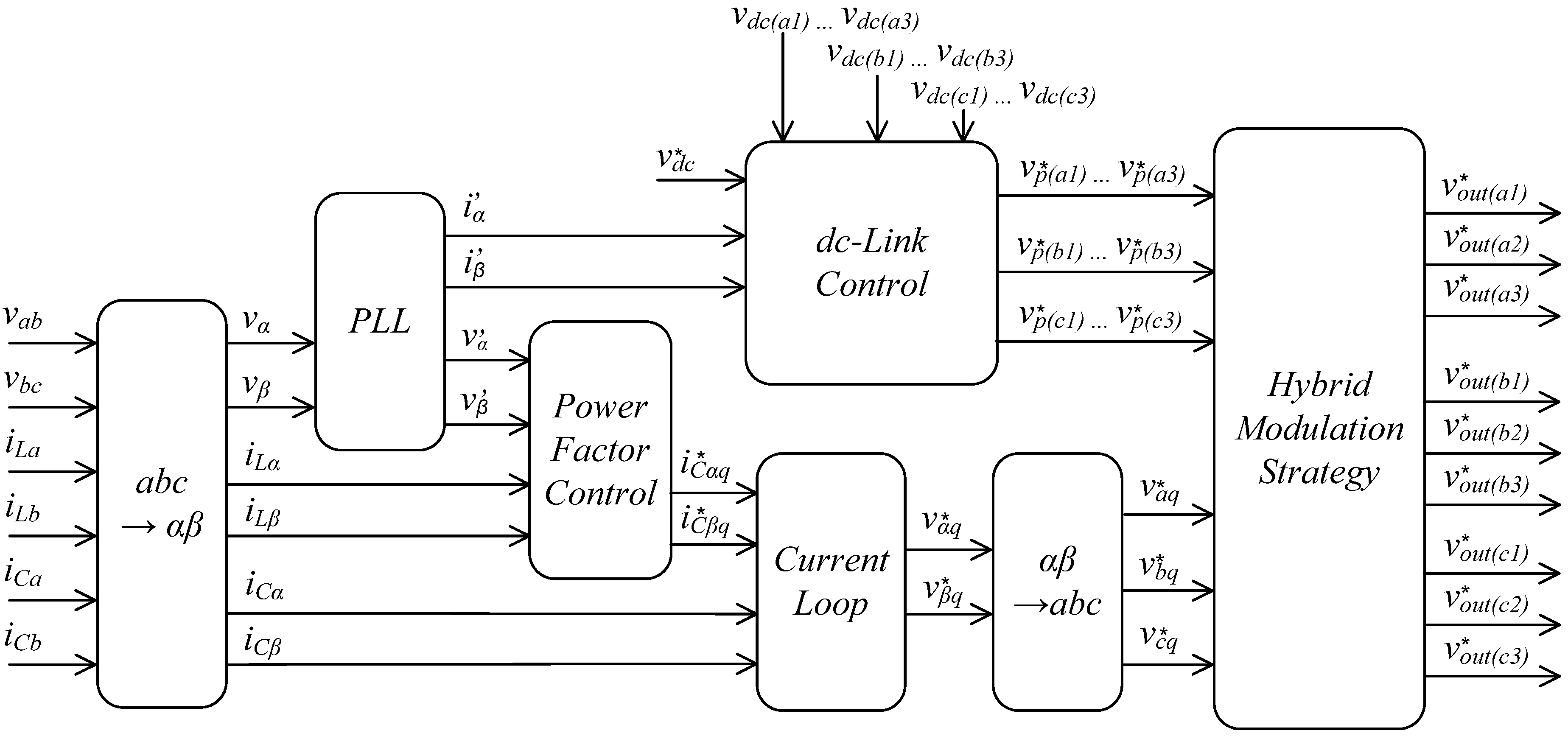
More details about the control loop that generates the reactive-power voltage references
are given in
Figure 5. The measured voltages (
and
) and currents (
and
) of the feeder are transformed into the αβ
0-reference frames by means of Clark transformation [
35], according to Equations (3) and (4). A phase-locked-loop control (PLL) is used to detect the phase and frequency of the fundamental positive-sequence component of the system voltage, already in terms of αβ–variables (
and
). The reactive compensating current references (
and
) are calculated using the definitions given in the p–q Theory through Equations (5) and (6). Finally, the current references and the generated converter currents are compared in the current loop controller, Equations (7) and (8), to determine the reactive-voltage references for power-factor compensation (
and
), which are subsequently transformed back to the
abc-reference (
,
and
) using Equation (9).
Figure 4.
Power and control circuit diagram.
Figure 4.
Power and control circuit diagram.
Figure 5.
Control circuit diagram.
Figure 5.
Control circuit diagram.
The blocks from
Figure 5 can be exploited from equations presented.
and are calculated using the same Equation (4).
From pq-theory, the reactive power is calculated. However, the oscilating component
is present and need to be eliminated by a low-pass filter.
Current loop
The current loop uses a PI control in order to synthesize the converter currents.
Hybrid modulation strategy
are internal variables of the hybrid modulation block. These parameters are input reference voltage to PWM modulation for the a-phase’ blocks. They are calculated from equations as presented below for a-phase:
, and are the normalized gate signals sent to IGBTs of the a-phase. The same logic is used for b and c phases of the converter.
4.2. DC-Voltage Control Loop
In an asymmetric multilevel converter topology, the optimum harmonic cancellation, as that provided by the carrier-shifting modulation, and the average dc-link control loop cannot be achieved. In fact, the different values of dc-link voltages make it almost impossible to use an average control for the dc-voltages of the power modules. Some studies have been proposed to solve this problem [
27,
28]. Nevertheless, these solutions do not present a generic dc-link regulation control loop for the asymmetric multilevel converter. Instead, they are particular solutions for each kind of application. In this paper, an improved dc-voltage regulator is proposed for each power module of the asymmetric multilevel converter that is suitable for multilevel D–STATCOM applications.
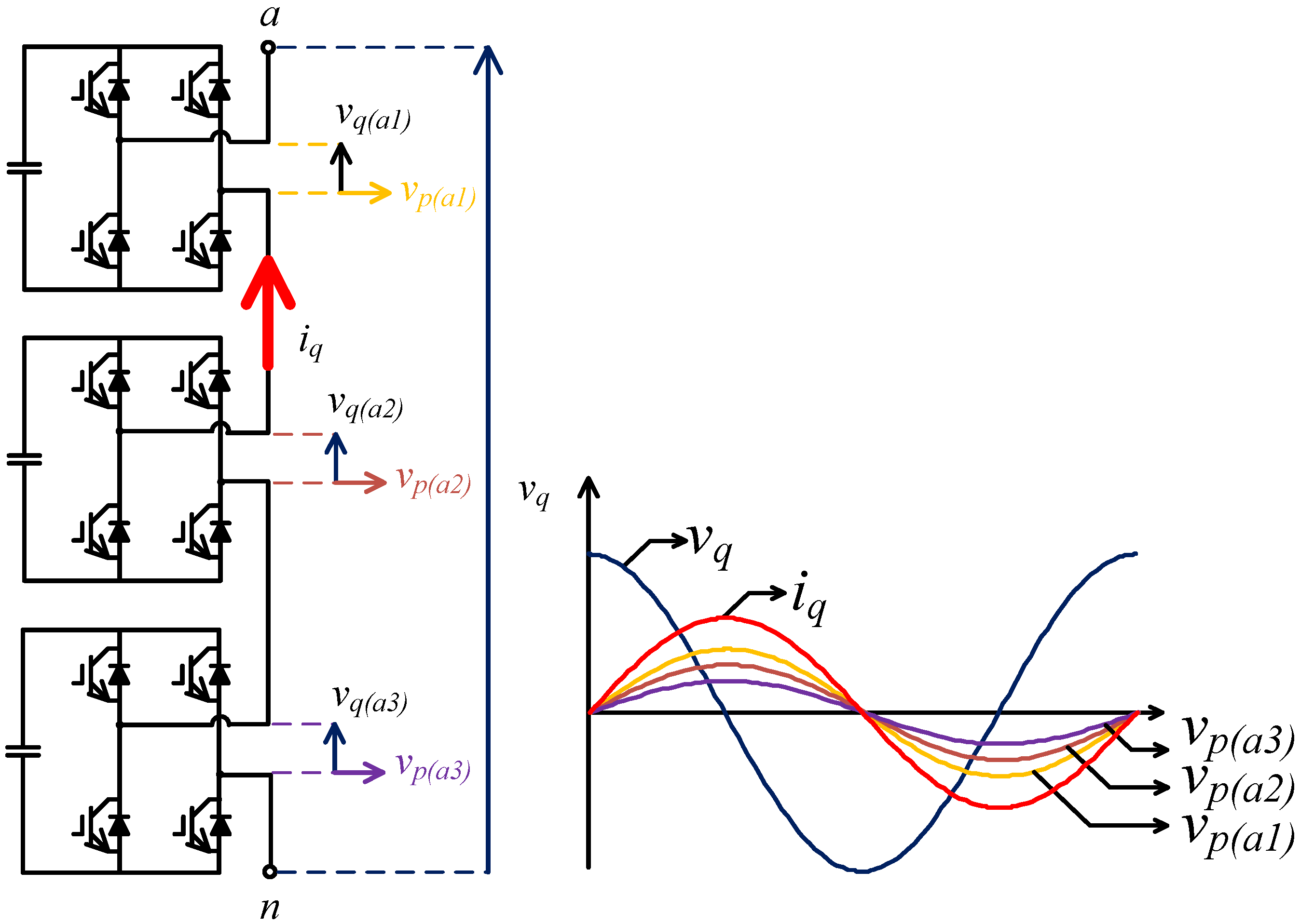
The series connection of the power modules with different nominal powers in a same leg of the asymmetric multilevel converter causes a problem, because they produce different losses to be compensated, whereas a same current is passing through the power modules.
Figure 6 illustrates the voltages in each power module and the current passing through them, in the a-phase leg of the converter. Active-voltage components should be added to the compensating voltage
vq of the D‑STATCOM to regulate the dc-voltages in each power module. In other words, the active-voltage components
vp with different amplitudes, but in phase with, or in phase opposition with, the current
iq should be added to the principal compensating voltage references
determined in the power factor control loop shown in
Figure 5. To overcome this issue, nine dc-voltage regulators, one for each power module, were included in the controller of the D–STATCOM.
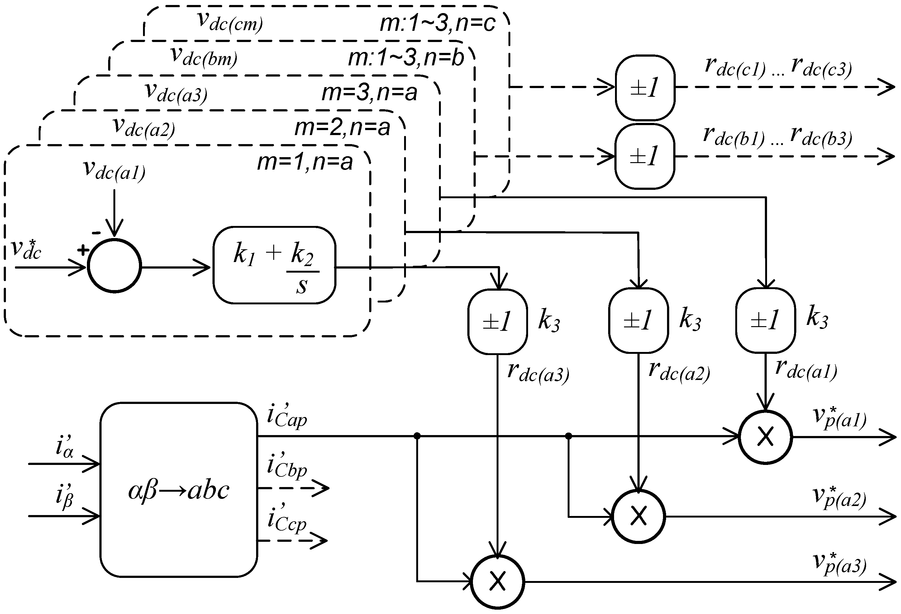
Figure 7 shows in details that one for the power modules of a-phase of the converter.
In order to promote an independent dc‑link control circuit, a minimum reactive current (
qmin) is calculated by the power factor control circuit and synthesized by the D–STATCOM. Thereby, an independent voltage signal can be calculated for each cell (
,
,
) and, together with the already circulating current (
), can maintain all the dc‑link voltages regulated.
Figure 6 illustrates the principle operation of the proposed dc‑link control circuit.
Figure 6.
Principle operation of dc link loop.
Figure 6.
Principle operation of dc link loop.
Figure 7.
Independent dc link control circuit.
Figure 7.
Independent dc link control circuit.
The dc‑link control circuit for a-phase of the D–STATCOM is illustrated in
Figure 7. In order to regulate the dc voltages, the control circuit compares a reference signal
with all the capacitor voltages, independent of the power level (
m = 1,
2,
3) or phase leg (
n = a,
b,
c), for example,
.
A PI-controller adjusts the resultant error signal. The output of the PI controller is multiplied with a unitary positive or negative parameter (k3), depending on the reactive power compensation (capacitive or inductive), generating a virtual resistance . The result of this operation is multiplied with a unitary sinusoidal signal (, which is synchronized through a PLL circuit, generating the active voltage reference for this cell (). The active voltage references added with the reactive voltage reference for each cell generate the voltage reference signals per cell that is used in the hybrid modulation strategy. The reference signals for the others cells use the same methodology and are also delivered to the hybrid modulation strategy circuit.
The main purpose of the unitary current signal ) is to provide accurate phase information to the dc-link control circuit. This signal could be synchronized directly by the D–STATCOM synthesized currents. However, it is well know that the output reactive current of the D–STATCOM is in quadrature, leading or lagging, with the bus voltage. Note that, in real applications, the bus voltage waveform presents a more constant behavior when compared with the current waveform, resulting in a more robust control. Therefore, the proposed control circuit uses the measured bus voltage in order to synchronize the unitary current signal ). For this reason, the output signals and are synchronized in quadrature with the bus voltage ( and ) and, at the same time, in phase or counter-phase with the injected current of the D–STATCOM. The unitary positive or negative parameter (k3) completes the synchronization circuit identifying the direction of the injected current.
Equations from (13) to (15) expresses the active control for the dc‑link only for a-phase cells (
n = a).
where the parameters
and
are gains of the controller. As already said, the unitary positive or negative parameter (k
3) completes the synchronization circuit identifying the direction of the injected current.
5. Experimental Section
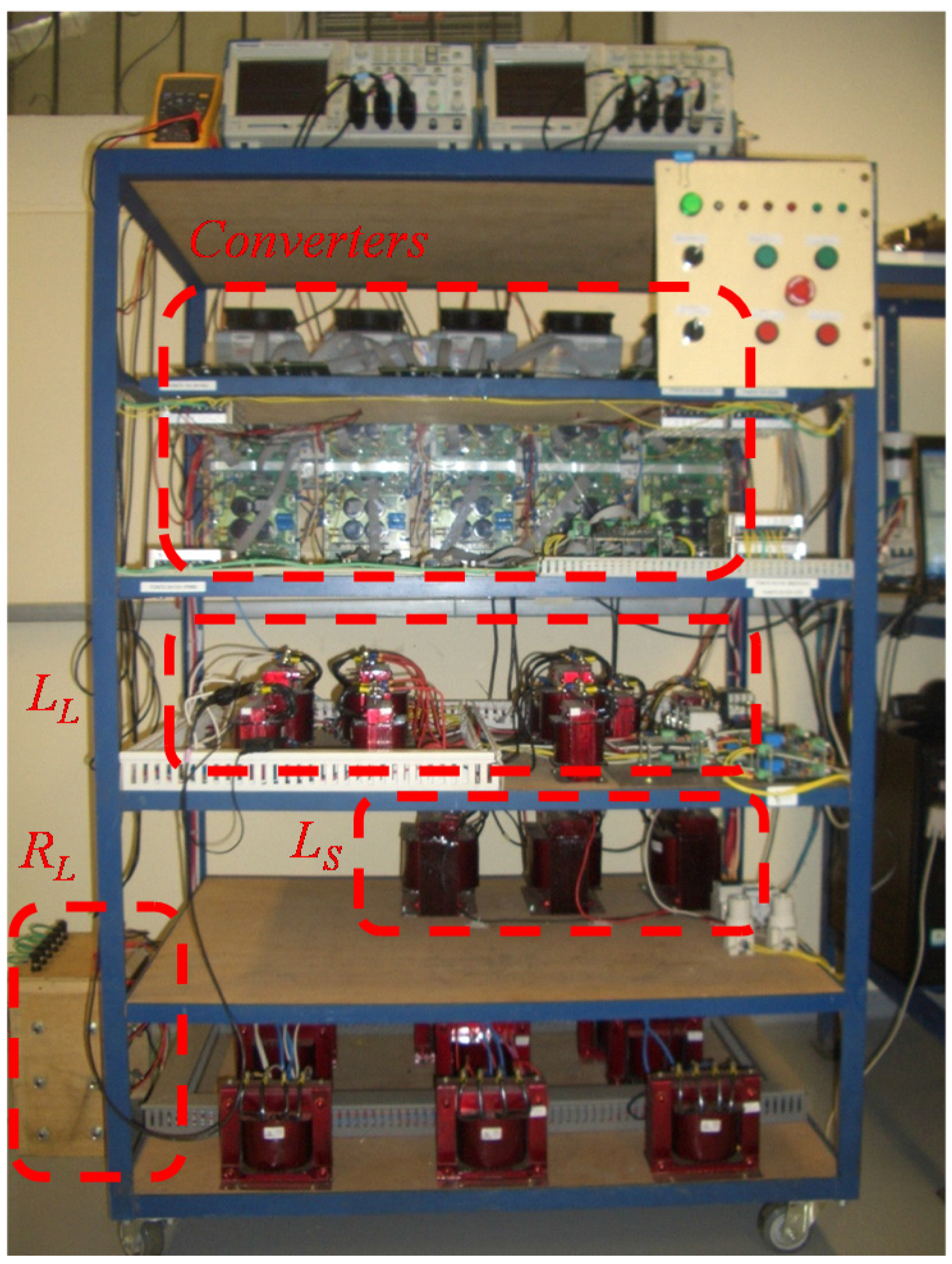
Experimental result of the downscaled D–STATCOM with the reactive control circuit is presented in this section in order to show the equipment and the dc-link control performance. The experimental results are obtained through a 2.0 kVA laboratorial prototype. The diagram circuit of the prototype is identical to that presented in
Figure 4 and the parameters are presented in
Table 2.
Table 2.
Power Circuit Parameters.
Table 2.
Power Circuit Parameters.
| Feature | Tag | Value |
|---|
| Voltage source (rms) | Vs | 220 V |
| Power | S | 2.0 kVA |
| Source impedance | LS | 2.4 mH |
| Converter impedance | LC | 5 mH |
| DC capacitance | CDC | 5.7 mF |
| Feeder load impedance | RL | 15 Ω |
| (inductive load) | LL | 30 mH |
The laboratorial prototype is composed of nine single-phase full-bridge inverter (SKS 15F B2CI 2P 03 V12 from Semikron), developed with the DSP platform (TMF320F28335 from Texas Instruments) and is presented in
Figure 8.
Figure 8.
2.0 kVA laboratorial prototype.
Figure 8.
2.0 kVA laboratorial prototype.
The experimental results of the D–STATCOM with the reactive control circuit is presented from
Figure 9 to
Figure 14.
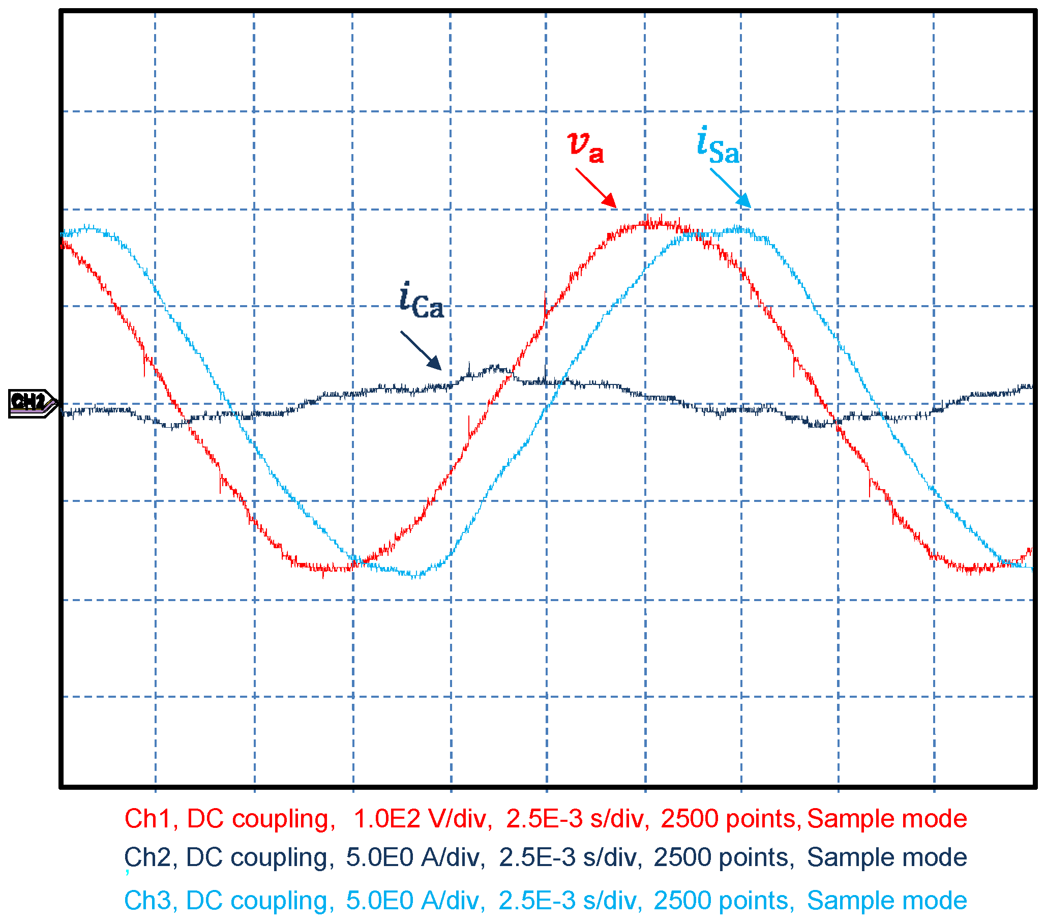
Figure 9 and
Figure 10 present the phase voltage of the bus (
), the source current (
) and the synthesized current of the D-STATCOM (
).
Figure 9.
Experimental results—power factor control turned off.
Figure 9.
Experimental results—power factor control turned off.
It can be observed in
Figure 9 that even when the reactive control is disabled, a minimum reactive current related to
qmin and with approximately 1.0 A (peak) is synthesized by the D–STATCOM (
iCa) in order to regulate the capacitor voltages. Without this minimum current it would be impossible to regulate each dc‑link voltage of the asymmetric converter.
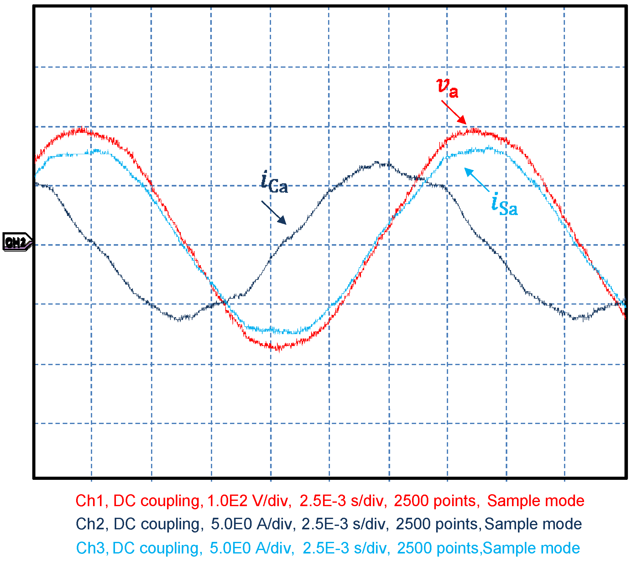
When the reactive control circuit is enabled, as shown in
Figure 10, the D–STATCOM corrects the power factor of the system (
in phase with
). Note that the synthesized current (
iCa) leads the phase voltage, in order to correct the inductive power factor of the load. The power factor reached by the control system was 0.996.
Figure 10.
Experimental results—power factor control turned on.
Figure 10.
Experimental results—power factor control turned on.
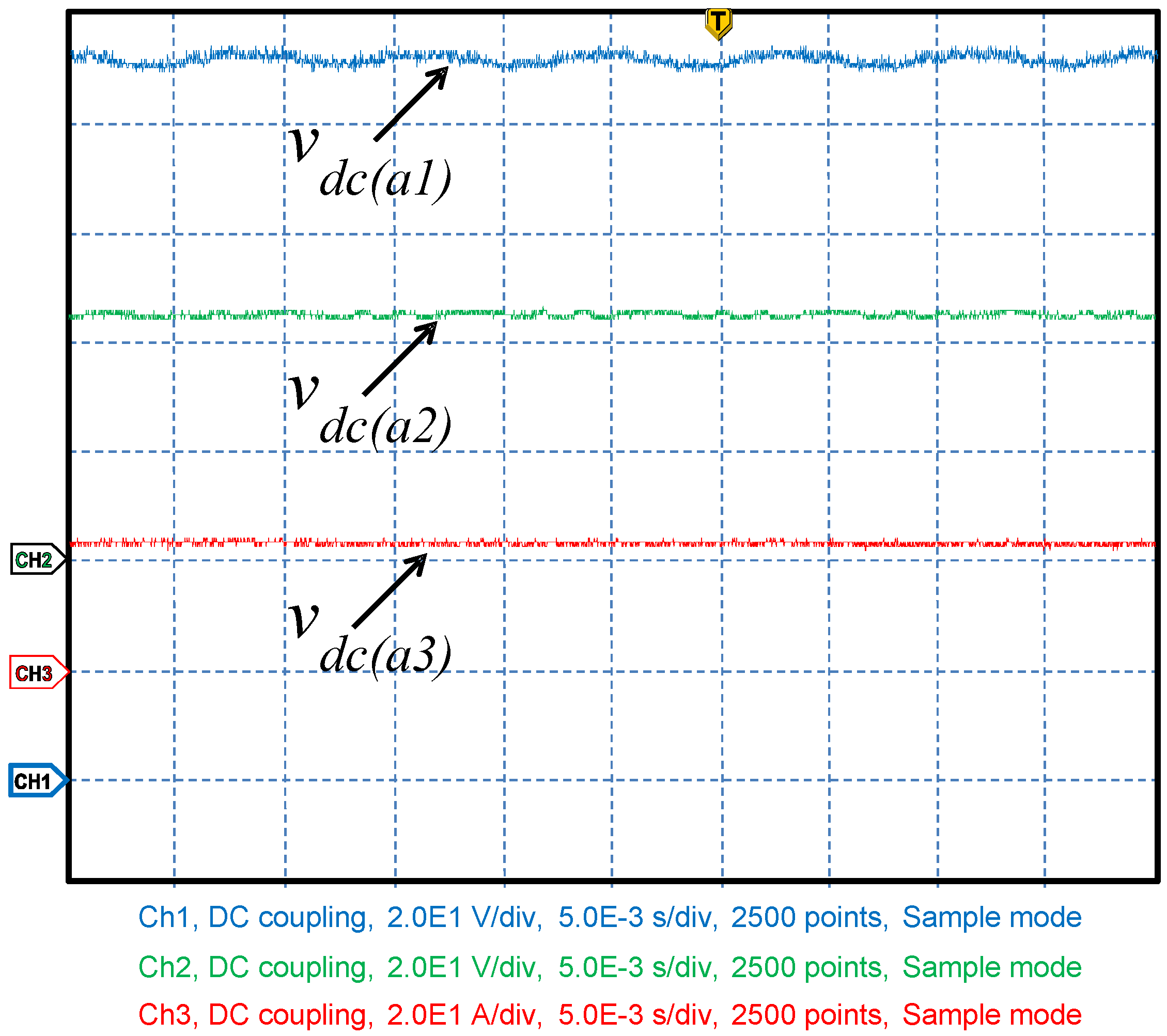
Figure 11 presents the regulated dc‑link voltages only for one phase of the multilevel converter, proving the performance of dc voltage control circuit. It can be observed that the values are in accordance with design values:
= 22 V,
= 44 V and
= 132 V.
Figure 11.
Experimental result—dc‑link voltage regulation.
Figure 11.
Experimental result—dc‑link voltage regulation.
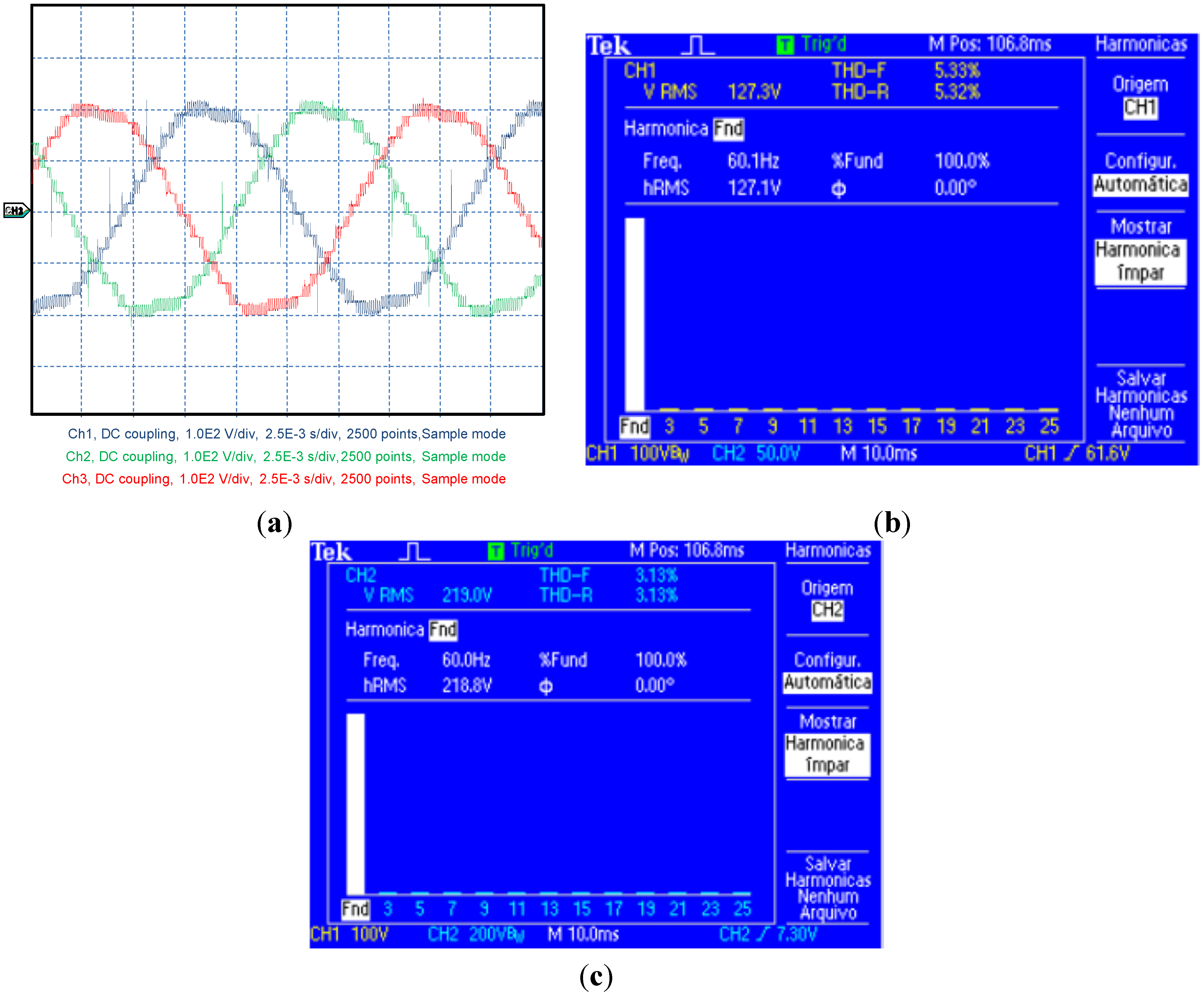
The power quality can be evaluated observing the total harmonic distortion-THD for voltages and total demand distortion-TDD for currents, as defined by IEEE [
29]. The output voltages measured at the converter are presented in
Figure 12a. It is possible to verify that the output voltages are balanced and are composed of nineteen voltage levels. However, it is also possible to identify that harmonics are present, which changes the waveform of the voltages. For this case, the THD measured for line-to-neutral and line-to-line voltage are presented in
Figure 12b,c. The measured values are 5.33% and 3.13%, respectively, which is smaller than those defined by IEEE (8.0%) and ANEEL (10.0%) recommendations for line-to-neutral voltage smaller than 1 kV. However, the results are obtained from a downscaled prototype for medium voltage applications. In this context, for greater voltage levels, between 1.0 and 13.8 kV, the THD recommendations for voltage are 5.0% and 8.0% for IEEE and ANEEL, respectively. It is known that THD will be the same for medium or low voltage because it is related to the waveform instead of voltage level. Thus, the solution proposed just meets the ANEEL recommendations. As observed in
Figure 12c, the line-to-line voltage presents an optimum harmonic cancelation when compared with the line-to-neutral voltage (reduction of 40.94%) proposed by the author in [
32] for three-phase applications.
Figure 12.
(a) Three-phase voltage converter waveform; (b) line-to-neutral THD; (c) line-to-line THD.
Figure 12.
(a) Three-phase voltage converter waveform; (b) line-to-neutral THD; (c) line-to-line THD.
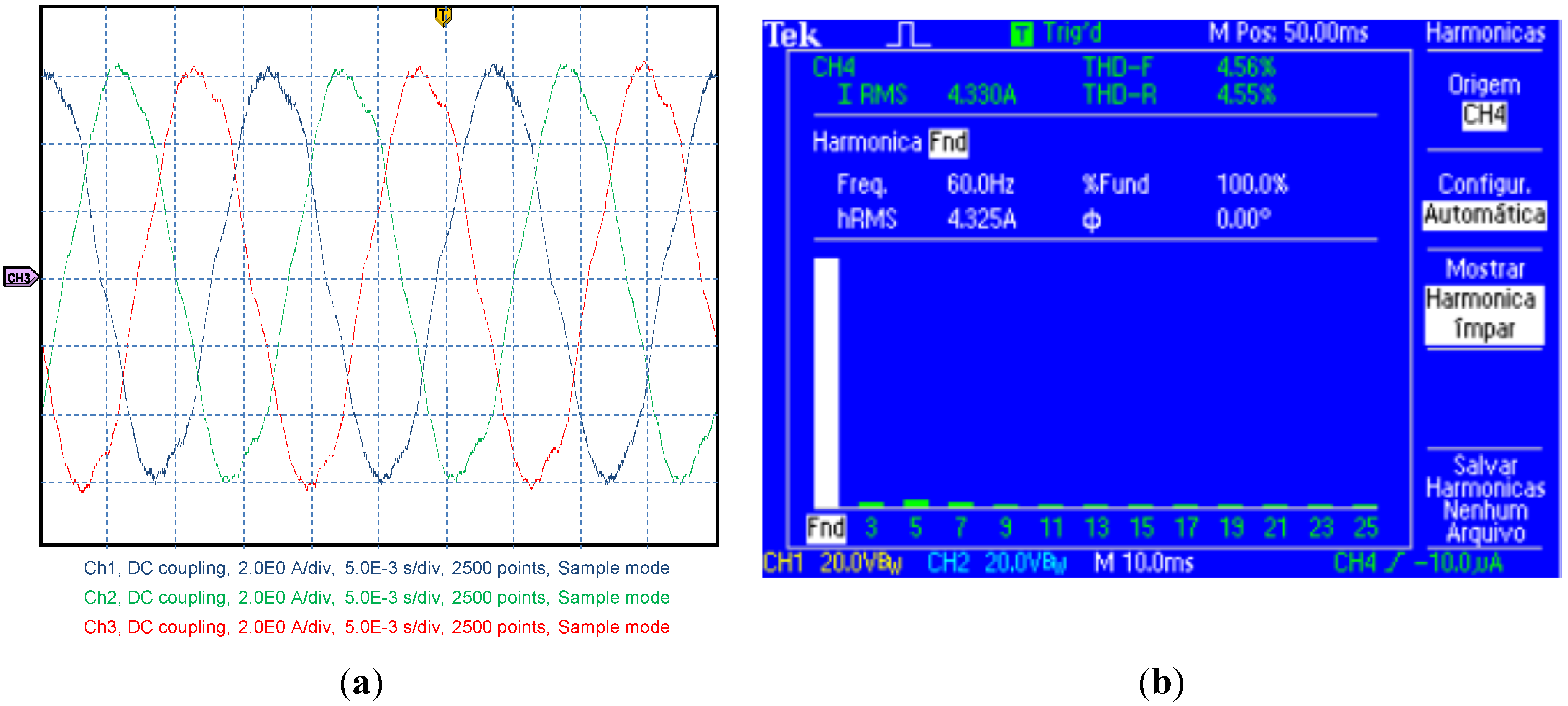
The three-phase current of the converter is presented in
Figure 13a. The harmonic current distortion is another important index used to evaluate the power quality of the equipment. This value is a relation between the maximum short-circuit current (
Isc) at PCC and the maximum demanded load current (
IL), and the rated voltage operation. For voltages between 120 V through 69 kV and a relation of
Isc/IL smaller than 20 (worst case scenario), the TDD must be smaller than 5.0%, following IEEE recommendations. In this context,
Figure 13a,b presents the current waveform and its total harmonic distortion, respectively. It can be observed that the total demand distortion is 4.56%, which attends the requirements.
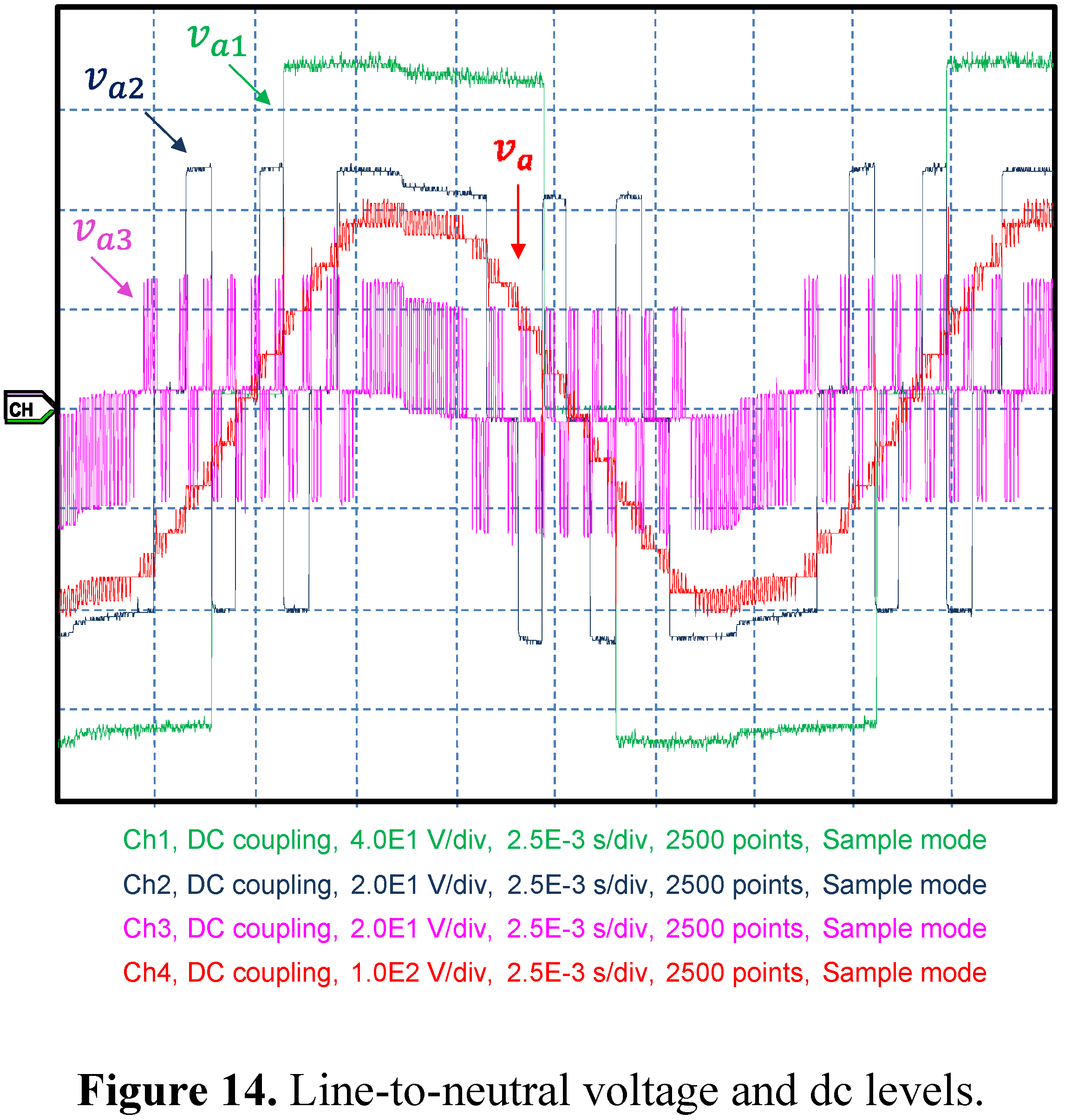
Figure 14 demonstrates the line-to-neutral voltage composition from each cell of the converter. The sum of different dc levels established under different switching methods gives the final line-to-neutral voltage
.
Figure 13.
(a) Three-phase current converter waveform; (b) TDD.
Figure 13.
(a) Three-phase current converter waveform; (b) TDD.
Figure 14.
Line-to-neutral voltage and dc levels.
Figure 14.
Line-to-neutral voltage and dc levels.
6. Conclusions
This paper presents an independent and improved dc-voltage control capable of regulating the isolated capacitors of an asymmetric converter, where a general solution for controlling different values of dc-voltages in an asymmetric multilevel converter does not exist. This solution adds an active-voltage component with different amplitude for each module to the reactive compensating voltage reference, leading to the desired control for each dc-voltages. Furthermore, the asymmetric converter uses an enhanced hybrid modulation, proposed by the authors, reducing the switching losses without compromising the optimized harmonic cancelation.
Both contributions proposed in this paper are carried out using a downscaled asymmetric multilevel D‑STATCOM. The STATCOM, using an asymmetric topology, demonstrated to be very efficient at controlling the reactive power, which is clearly observed in the Experimental Section through and waveforms. The operation principles and experimental results of the proposed dc-voltage control and enhanced hybrid modulation were presented in this paper to prove the adequate performance of the improved asymmetric cascaded multilevel D-STATCOM.


