1. Introduction
Because many traffic accidents are the consequence of a loss of control of the vehicle, various Advanced Driver Assistance Systems (ADAS) are developed in order to precisely measure in real time the lateral position of the vehicle in the traffic lane and finally to assist the driver by correcting the trajectory in case of run-off-road situations.
Many Systems use optical sensors to detect the lateral white strips on the road [
1,
2,
3]. Classical lane detection algorithms utilize different lane patterns with 2D or 3D road models considering straight or curved situations but they lack flexibility. The B-Snake model by taking into account perspective effects is able to recognize a large range of lane profile and is quiet robust against shadows, lighting variations, noises [
4]. Cluttered edge, shadows, intermittent lane and so on can lead to erroneous line detection. By combining vision systems with DGPS and other sensors one can improve in lane positioning [
5] and more recently, “sensor data fusion” systems [
6,
7] estimate the position and the status (pitch, roll) of the vehicle. They present some improvement in adverse weather conditions.
Nevertheless, all vision-based systems are sensitive to rain, snow, fog and other environmental conditions, situations for which assistance systems are of particular interest. Though GPS are little affected by weather conditions, there are situations where they cannot be used. Moreover, they are not sufficiently accurate for lateral positioning.
There remains a category of systems almost insensitive to environmental weather conditions which imply benefits in installing markers on the roads. For instance, there is a system that uses improved “cat eyes” disposed on road in conjunction with a 38 GHz radar [
8]. Another uses passive magnetic markers embedded in the road [
9,
10,
11]. The static magnetic field generated by these markers is indeed particularly appropriate for that application because it is not disturbed by any form of water. A magnetic marker must be regularly disposed on the center of the lane. Unfortunately, these systems are costly which prevents their wide scale use. In order to reduce the cost, a system using magnetic painted strip in the middle of the lane has been developed [
12]. It allowed in addition to embedding infrastructure information in the strips. As the magnetic field rapidly decreases with the distance, it is impossible to paint those strips on the side of the lane and when painted in the middle of the lane, the strip may disturb drivers by creating visual artifacts by night.
In this paper, we describe a cooperative vehicle-infrastructure system whose principle is described in [
13,
14]. It includes passive flat electromagnetic transponders integrated in the lateral white strips and an on-board system able to detect these transponders. This system determines the distance between the lateral strips and the vehicle. This cooperative system operates in the UHF band, providing a large penetration depth in water and snow. Moreover, transponders are very cheap (a few cents), since they consist in a printed half wave antenna and a flat dye SAW resonator. They are easy to install with existing line painting machines.
The paper firstly recalls the system principle. Then the influence of various spurious environmental elements is studied in order to estimate the robustness of this system in more real conditions. Measurements were performed for all considered situations to verify whether the precision remains sufficient.
2. Principle of Operation
The cooperative system described in [
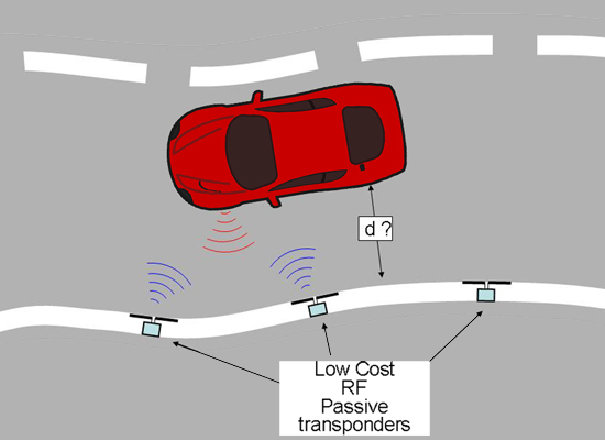
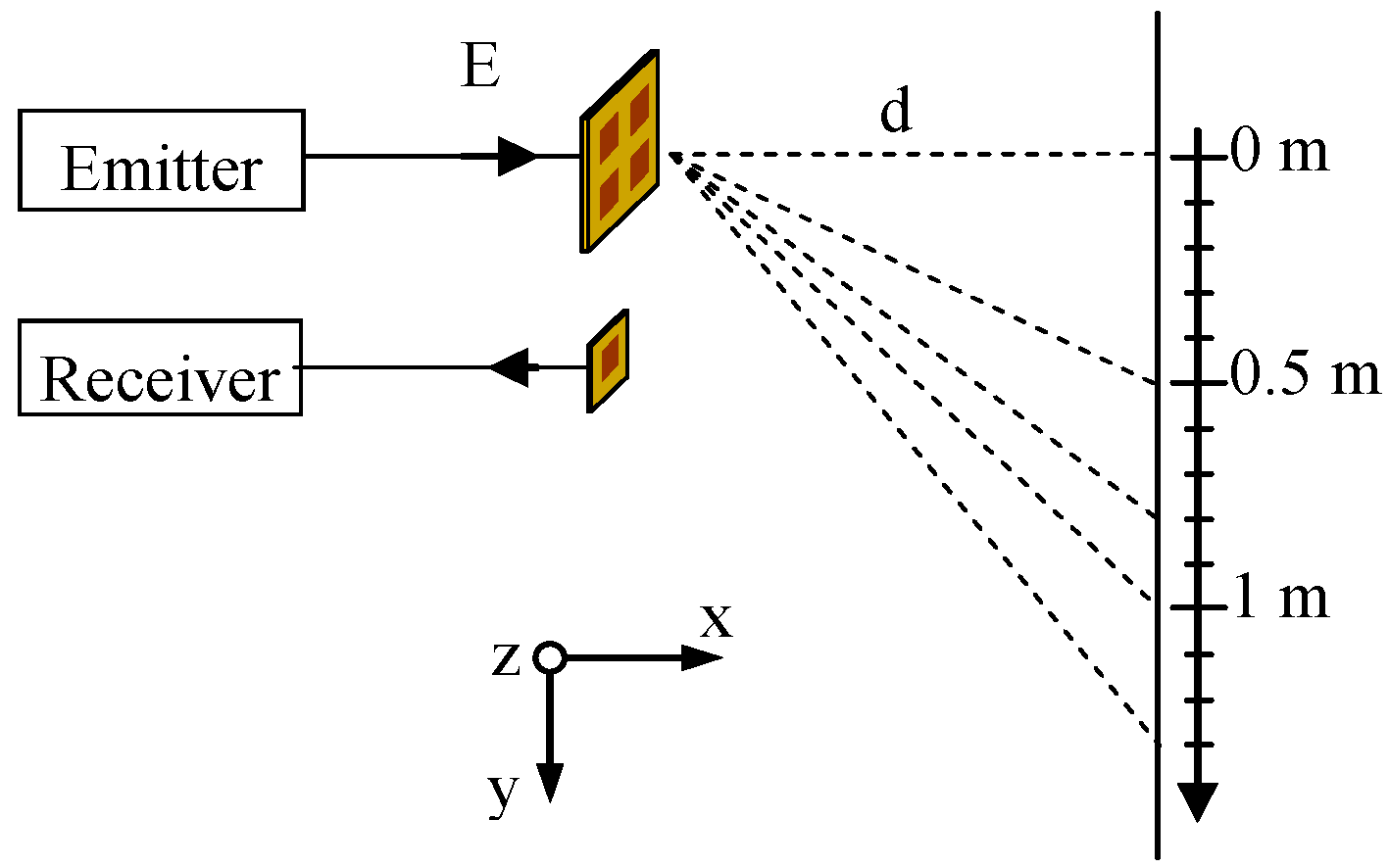
14] is composed of two components (
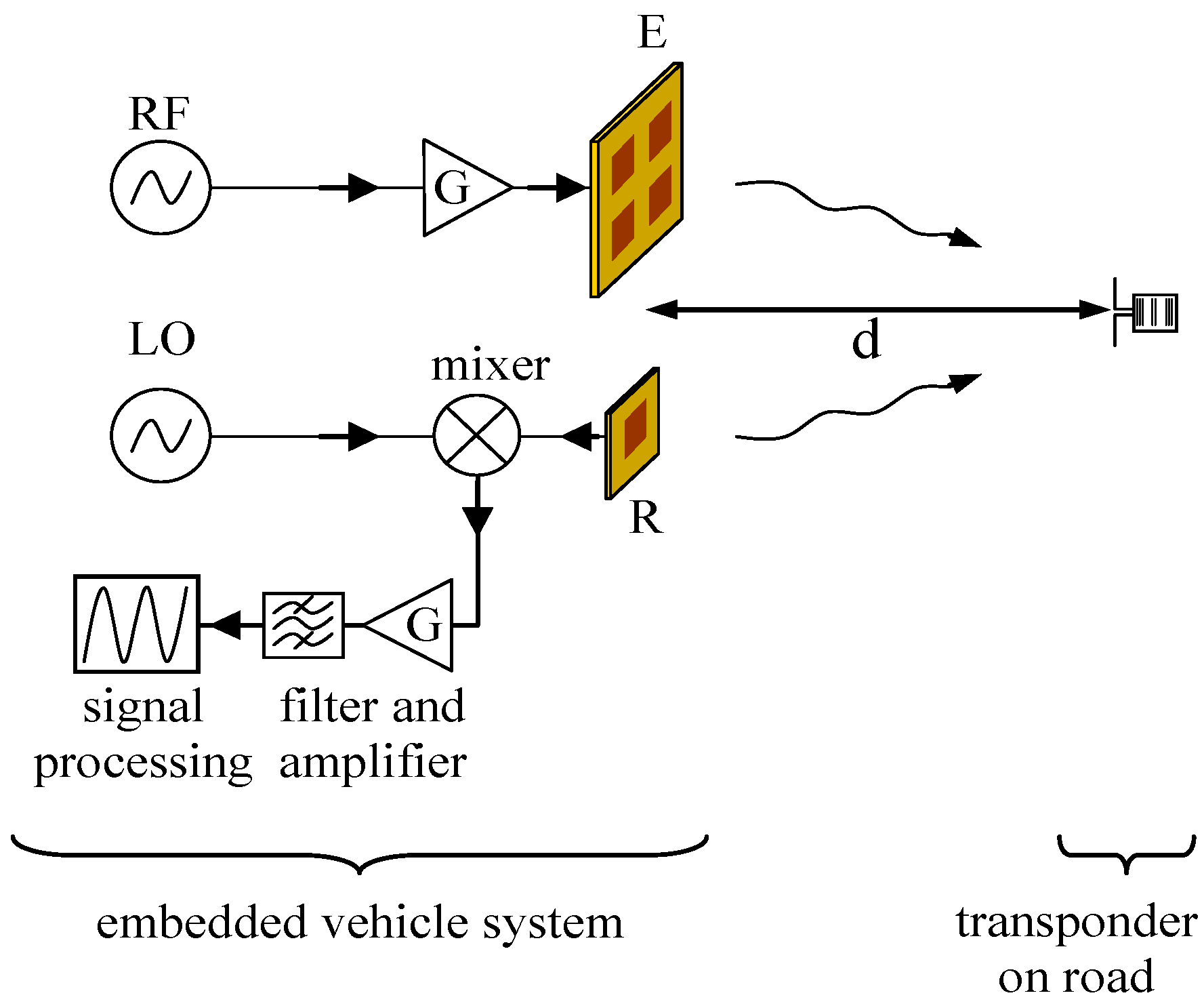
Figure 1): an embedded vehicle system and passive transponders integrated in the road. The on-board emitting antenna is fed by a 10 dBm RF signal at frequency fin the 867.5–869.5 MHz range. It is partially reflected by the transponders in all directions. A fraction of the reflected power is received by the on-board receiving antenna. The received wave is mixed with a local oscillator of frequency
f + 10 kHz. An active low-pass filter eliminates the high frequency resulting from the mixing and amplifies the low frequency. The resulting signal at 10 kHz is then digitized and used for the numerical treatments. The received signal includes the signal reflected by the transponder and all parasitic reflections. In order to make possible the extraction of information, a Surface Acoustic Wave resonator operating at
f0 = 868.3 MHz with a very narrow bandwidth of 300 kHz is included inside the transponder. This resonator adds a signature to the reflected wave which makes it more easily identifiable and allows the separation of the useful signal from the noise.
Figure 1.
Experimental setup of the cooperative system.
Figure 1.
Experimental setup of the cooperative system.
The signal received by the receiving antenna is processed and digitized in order to extract precisely the transponder response. As the measured signal
S(
f) is the sum of the ambient electromagnetic noise and of the reflected waves from transponder, the algorithm separates the transponder response from the electromagnetic noise using Equation (1) that models this superposition in the frequency domain:
where
P represents the propagation to and from the transponder,
R the resonator response transponder assimilated to a band-pass filter resonator, and
N(
f) all electromagnetic noises including parasitical reflections.
f is the frequency,
d the distance between vehicle and transponder,
A and φ are the amplitude and phase due to propagation,
f0 is the central frequency of the SAW resonator,
Q its quality factor and
.
The noise
N(
f) is completely unknown. Nevertheless, as it varies slowly with frequency by comparison with the SAW response, it can be represented by a polynomial function of maximal order 3 with complex coefficients. A fitting algorithm determines the optimum parameters
Q,
f0,
A, φ and the
N(
f) polynomial coefficients that well reconstruct the measured signal. This algorithm is based on the Nelder-Mead Simplex Method [
15] where the criterion is the square absolute value of the complex error. The phase φ is then used to extract the distance d using Equation (2):
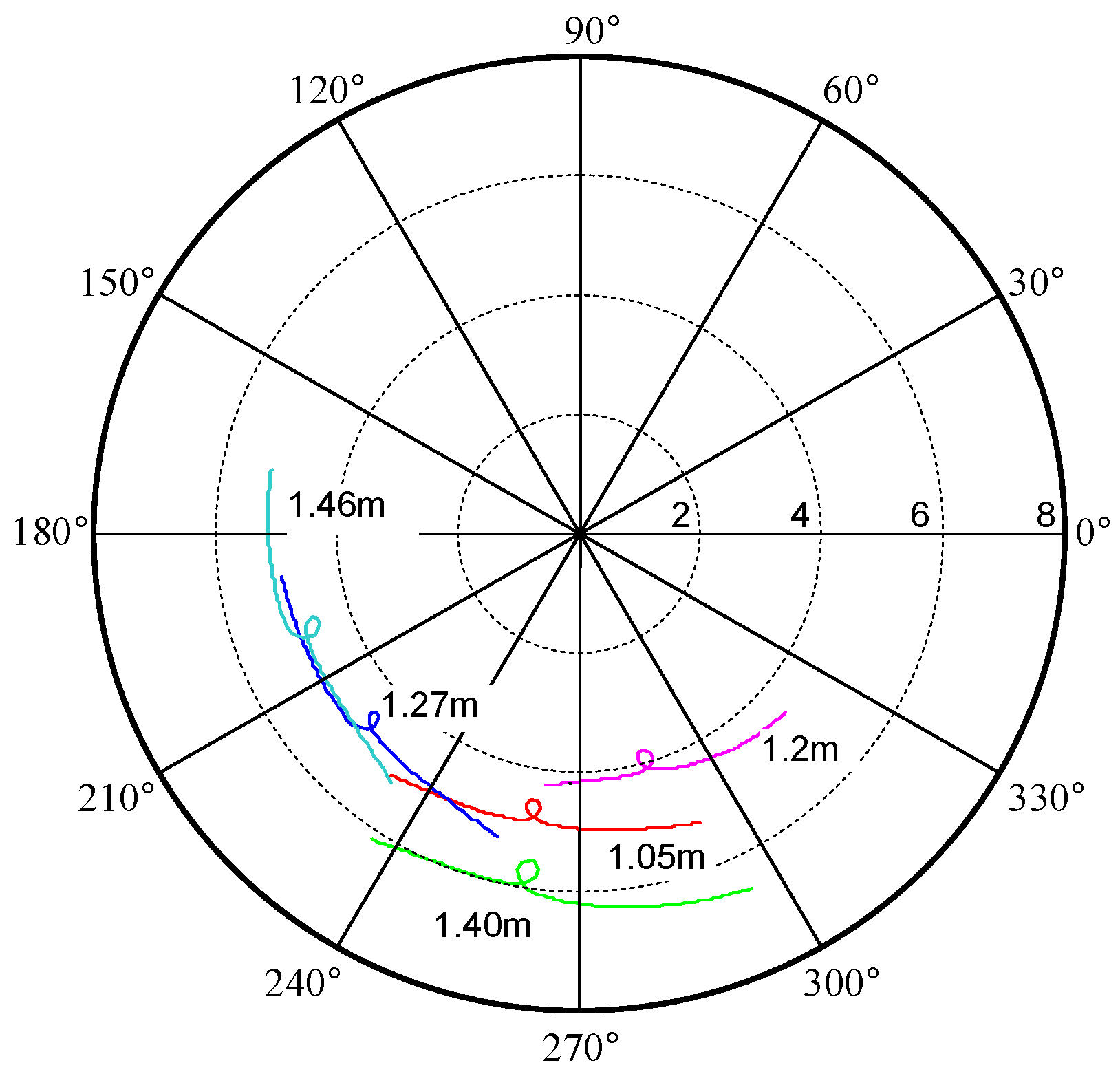
The behavior of the system has first been characterized in anechoic chamber for a distances d from 0.17 to 2 m.
Figure 2 shows the measured signals for some transponder distances. It can be observes that the transponder is indeed detected via identification of the loops corresponding to the SAW resonator response.
Figure 2.
Measured signals in ideal environment.
Figure 2.
Measured signals in ideal environment.
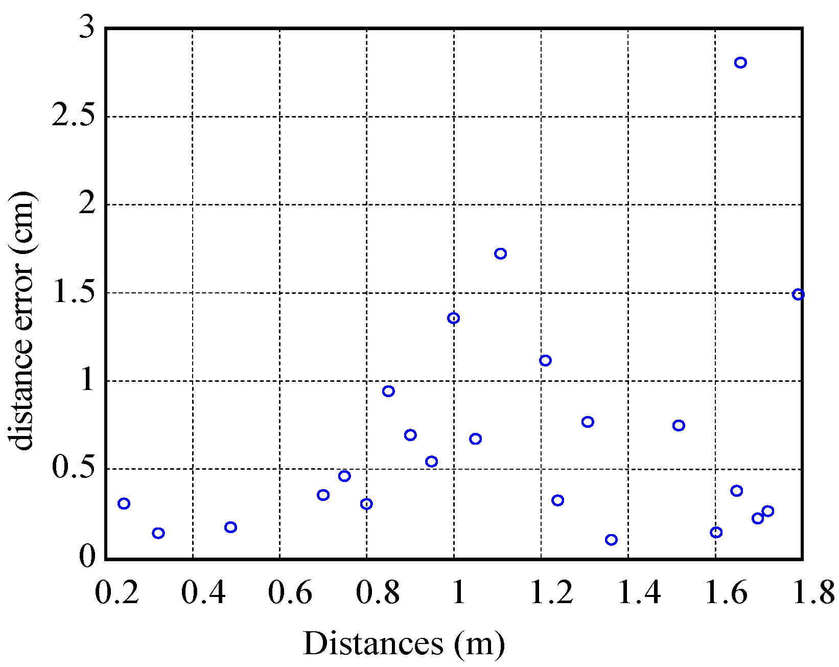
Figure 3 shows the relative error between the distance estimated from the phase φ calculated by the and real distance. It can be noticed that this error is less than 3 cm, with a median of 0.5 cm.
Figure 3.
Estimated distance errors.
Figure 3.
Estimated distance errors.
3. Evaluation of the Robustness of the System
The robustness of the developed system has been evaluated to take into account a realistic environment. For this reason, two experiments were performed to evaluate the influence of some parasitic metallic elements on the on-board antennas and the transponder, and the influence of the physical properties of the road on the transponder behavior. A third experiment evaluates the robustness of the system in presence of an array of transponders.
3.1. Complex Environment
The presence of parasitic elements around the transponder and the metallic components of the vehicle can introduce errors in the estimation of the lateral vehicle position. In order to evaluate the robustness of the system, the experimental setup described previously was characterized by introducing some large metallic reflectors around the transponder and the antennas [
14].
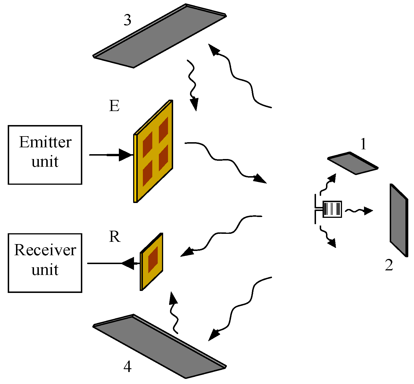
Figure 4 presents an example of the arrangement of several metallic reflectors of at least 30 cm wide square plates disposed around the setup very close to antennas and transponder.
Figure 4.
Position of the parasitic reflectors around setup.
Figure 4.
Position of the parasitic reflectors around setup.
Figure 5.
Distance error estimated in complex environment.
Figure 5.
Distance error estimated in complex environment.
The
Figure 5 shows the distance error in the complex environment of
Figure 4. Despite the great influence of the noise introduced by the reflectors, the optimization algorithm still allows the determination of the distance with a good accuracy. The error is less than 2 cm which is comparable to the one obtained without reflectors (ideal case). It can be concluded that the optimization method is almost insensitive to spurious reflections thanks to the detection of the transponder signature.
3.2. Bitumen Behavior
The experimental results presented previously are obtained when the transponder hangs in the air. Actually, the transponder will be integrated in the road. The road surface is composed of asphalt, also known as bitumen. It is then necessary to study the robustness of the algorithm considering the electrical properties of the bitumen. The electrical nature of materials can be described by their permittivity, which influence the distribution of electromagnetic fields in the material, and which determine the behavior of the materials in electric field. The permittivity can be represented as a complex quantity:
where
, ε
0 is the permittivity of free space and ε
r the relative dielectric constant.
In the UHF band, various studies indicate that the real part of bitumen relative permittivity is equal to 2.5.
A new antenna for transponder has been developed considering the bitumen permittivity. In the vicinity of bitumen, the wavelength λ
bit at
f0 = 868.3 MHz is expressed as follows:
where λ
0 is the wavelength in vacuum (λ
0 = 34.55 cm) and
is the real part of the effective relative permittivity taking into account all materials around the resonant antenna.
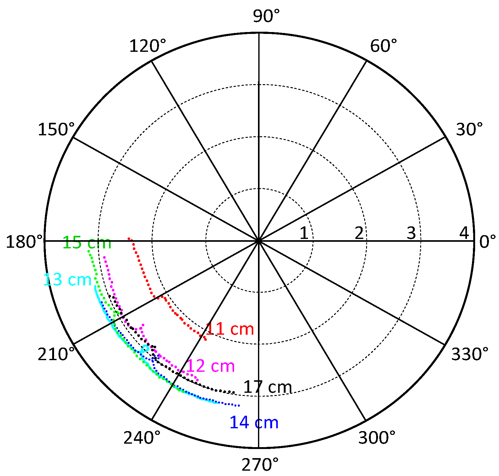
Figure 6.
Fitted signals in presence of bitumen for different lengths of the transponder antenna
Figure 6.
Fitted signals in presence of bitumen for different lengths of the transponder antenna
Different transponder antenna lengths were tested in an anechoic chamber in order to tune the antenna resonance around 868.3 MHz. The antenna is then placed on the bitumen and the transponder interrogated.
Figure 6 shows that the better matched antenna has a length of 13 cm. That value leads to a relative effective permittivity of the antenna environment equal to
= 1.77, which is close to the average permittivity of air and bitumen in equal shares.
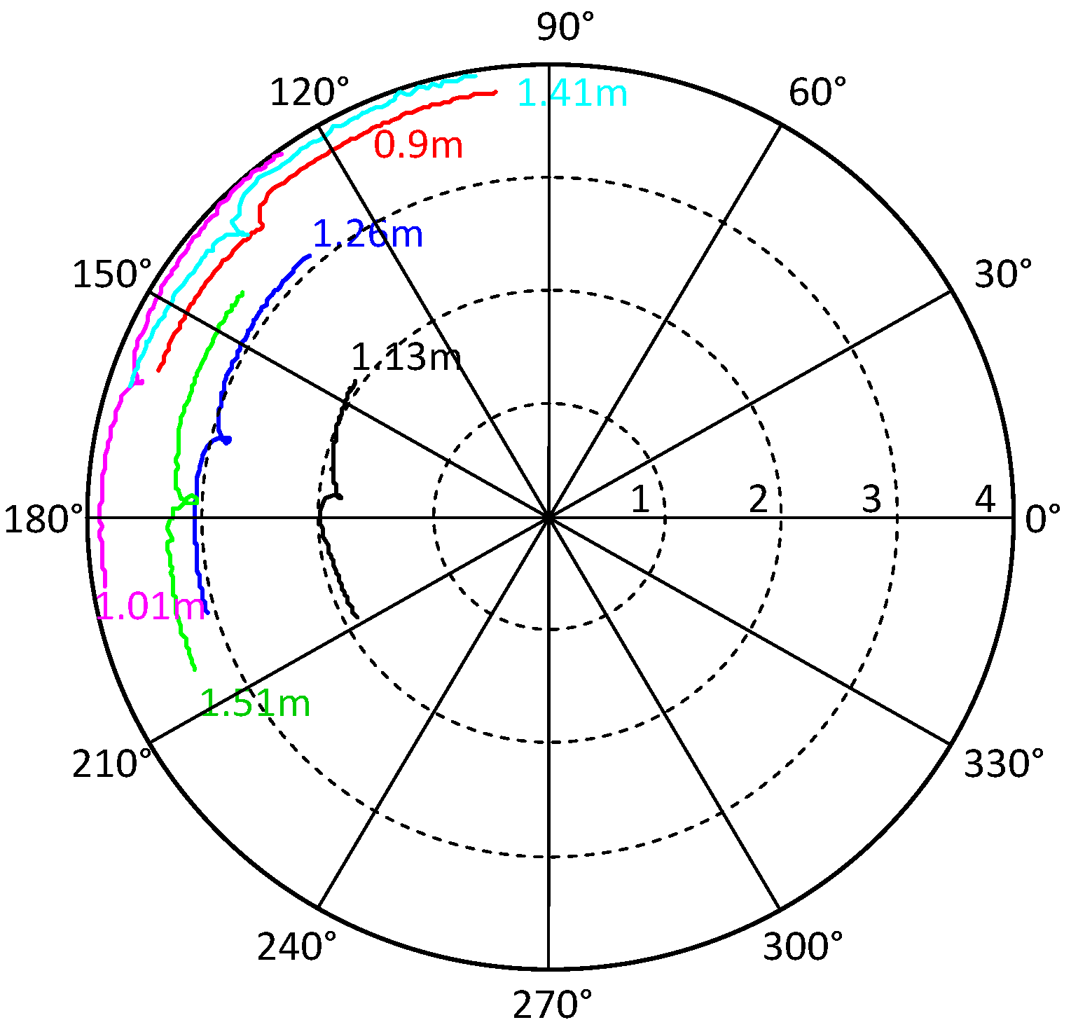
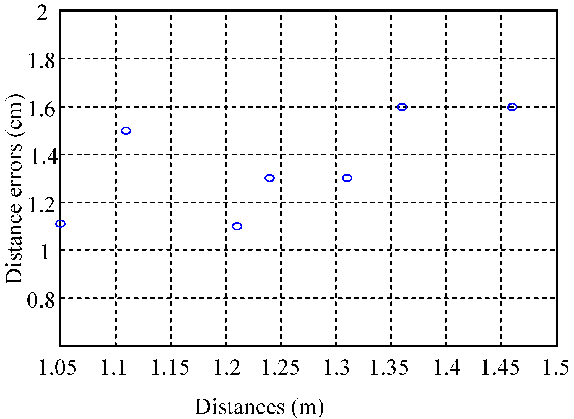
The tuned transponder with a antenna length of 13 cm was then used at different distances d ranging from 0.9 m to 1.51 m. The
Figure 7 shows curves obtained by applying the optimization algorithm.
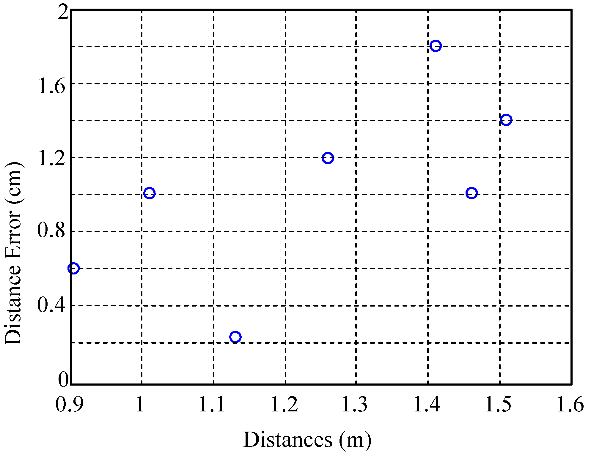
For each curve, the optimization algorithm allows to obtain the optimal phase φ which directly gives the distance d between antennas and transponder. As shown in
Figure 8, the distance error between the estimated distance and the real distance is less than 2 cm. The presence of a material with a very different permittivity next to the transponder does not perturb its performances.
Figure 7.
Fitted signals in presence of bitumen for different distance.
Figure 7.
Fitted signals in presence of bitumen for different distance.
Figure 8.
Relative distance error estimated in presence of bitumen.
Figure 8.
Relative distance error estimated in presence of bitumen.
3.2. Influence of the Interaction between Transponders
The developed system must be able to determine the lateral vehicle position in real time. It requires the integration of transponders periodically distributed along the road. However, the interaction between these transponders can have a significant impact on the robustness of the system. Two transponders (T
1 and T
2) were used in order to evaluate this interaction. As shown in
Figure 9, T
1 and T
2 are positioned on the same axe (Oy). The transponder T
1 is placed at a fixed position
y = 0 in front of emitter, while the transponder T
2 is placed at various positions
yi (
i = 1,2,3,4) along the y axis for a distance between axis Oy and emitter equal to 1 m.
Figure 9.
Experimental setup with the presence of two transponders with T1 fixed in front of emitter and for T2 position varying from y = 0.5 to 1.3 m.
Figure 9.
Experimental setup with the presence of two transponders with T1 fixed in front of emitter and for T2 position varying from y = 0.5 to 1.3 m.
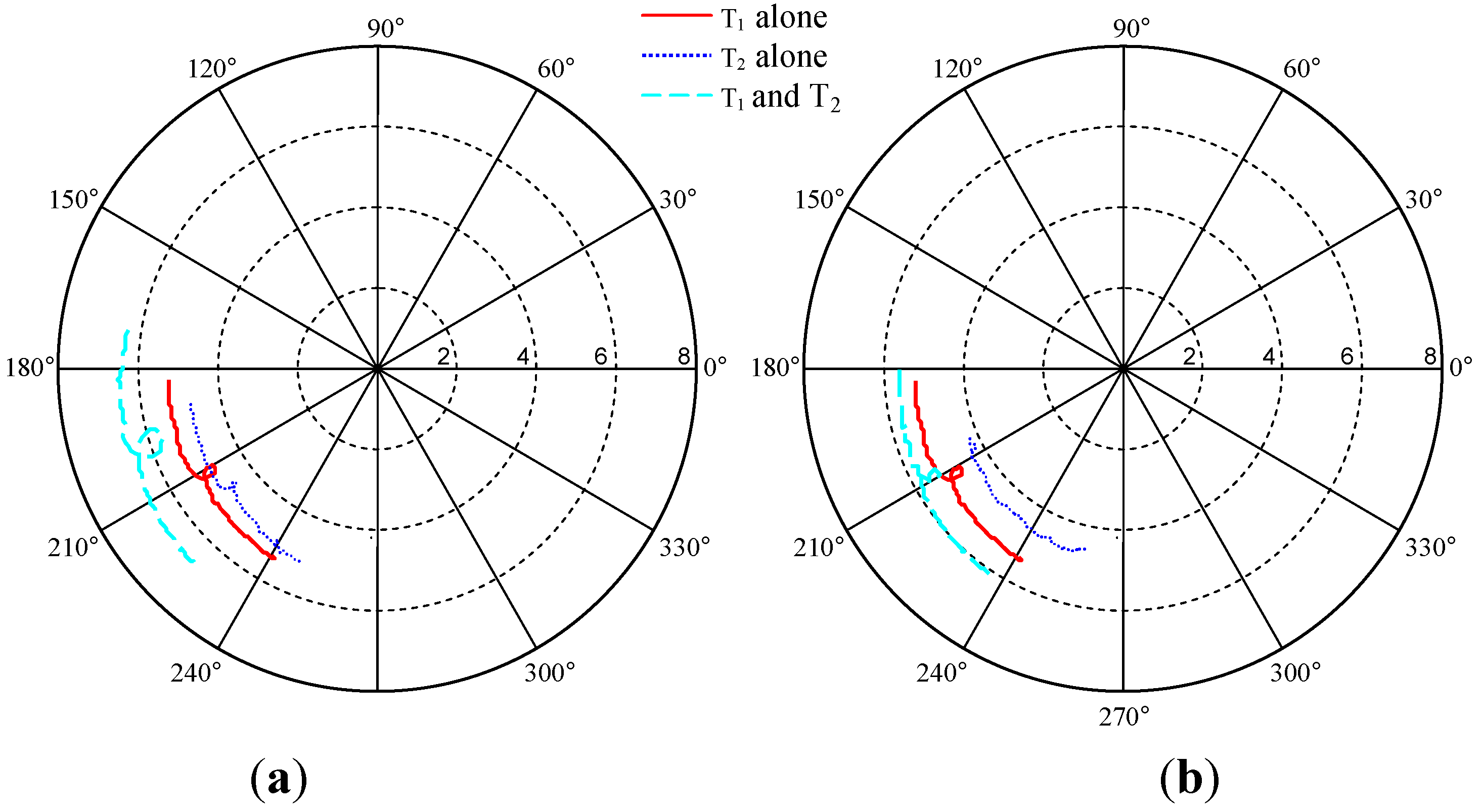
This experimental setup was characterized in an anechoic chamber. Three configurations have been tested: (1) T
1 without T
2; (2) T
2 without T
1; (3) both transponders. For each configuration, the amplitude and phase of the result signal are extracted by using the same method as described previously. The
Figure 10a illustrates the measurements for the three configurations with T
2 placed at 0.5 m whereas the transponder is placed at 1.3 m in the
Figure 10b. In
Figure 10a, we can see a great difference between the loop response with only T
1 and the one when T
1 and T
2 are present. This behavior disappears when the position of the transponder T
2 exceeds 1 m as seen in
Figure 10b. This is coherent with the fact that the system doesn’t see the transponder T
2 when it is placed at
y = 1.3 m. Indeed no loop is observed on the obtained signal with T
2 alone at this position (
Figure 10b blue curve). These perturbations can be understood as the superposition of waves reflecting from both transponders, which produce constructive or destructive interferences and by the mutual coupling between the two transponders.
Figure 10.
Measured signals for the three configurations, with T1 fixed in front of the emitter and for T2 placed (a) at y = 0.5 m or (b) at y = 1.3 m.
Figure 10.
Measured signals for the three configurations, with T1 fixed in front of the emitter and for T2 placed (a) at y = 0.5 m or (b) at y = 1.3 m.
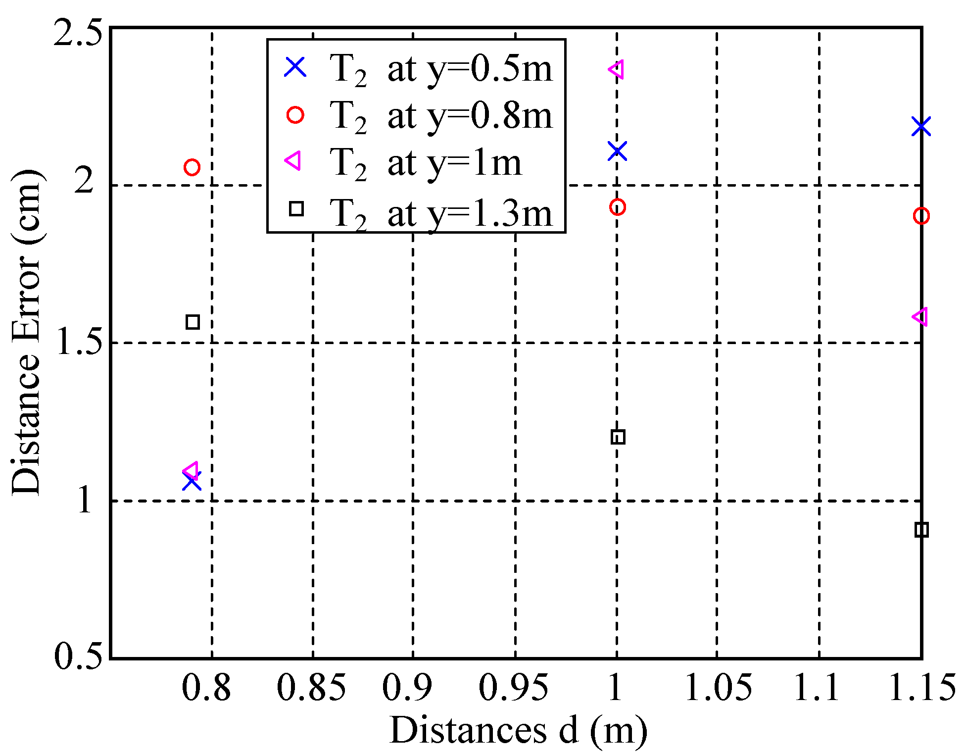
The
Figure 11 shows the distance error estimated with the two transponders. The presence of a second transponder, whatever its position, does not perturb very much the distance evaluation since it is still estimated with an error less than 2.5 cm.
Figure 11.
Distance errors estimated with two transponders, with T1 fixed in front of emitter and for various T2 position y = 0.5 to 1.3 m.
Figure 11.
Distance errors estimated with two transponders, with T1 fixed in front of emitter and for various T2 position y = 0.5 to 1.3 m.
4. Conclusions
This paper describes a solution based on a radio-frequency system, able to estimate the vehicle position in its lane in various representative environments. The system presented is composed of electromagnetic reflectors integrated in the lateral white strip of the road and embedded sensors in the vehicle. The resonant signature of reflectors is used to separate the useful signal from environmental noises, and to estimate the distance between the vehicle and the lateral white strip. Thanks to an optimization algorithm, the system exhibits a precision better than 3 cm in the evaluation of the distance from the reflectors in the range (0.2–2 m) in laboratory experimental conditions, even in presence of large artificial parasitic reflectors. The efficiency of this system is maintained in a realistic environment even with the proximity of bitumen under transponder and with other transponders placed around.
Because these results are encouraging and the system seems compatible with a wide scale implementation due to its low cost, this system will be implemented in a vehicle to be tested in real conditions.
Author Contributions
Nabil Houdali has performed both manipulations and calculations. The principle of the system has been imagined by Stephane Holé, Emmanuel Géron, Jérome Lucas and Thierry Ditchi. All the authors participated to the result analysis, algorithm improvement and method validation. Stéphane Holé is the supervisor of the Instrumentation Group. Finally all the authors have brought in turn key contributions to this work.
Conflicts of Interest
The authors declare no conflict of interest
References
- Ohzora, M.; Ozaki, T.; Sasaki, S.; Yoshida, M.; Hiratsukat, Y. Video-rate image processing system for an autonomous personal vehicle system. In IAPR Workshop on Machine Vision Applications 90, Tokyo, Japan, 28–30 November 1990; pp. 389–392.
- Chen, M.; Jochem, T.; Pomerleau, D. AURORA: A vision-based roadway departure warning system. In Proceedings of the Intelligent Robots and Systems 95; “Human Robot Interaction and Cooperative Robots”, Proceedings; IEEE/RSJ International Conference, Pittsburgh, PA, USA, 5–9 August 1995; Volume 1, pp. 243–248.
- Kang, D.J.; Choi, J.W.; Kweon, I.-S. Finding and tracking road lanes using “line-snakes”. In Intelligent Vehicles Symposium, Tokyo, Japan, 19–20 September 1996; pp. 189–194.
- Wang, Y.; Teoha, E.K.; Shenb, D. Lane detection and tracking using B-Snake. Image Vis. Comput. 2004, 22, 269–280. [Google Scholar] [CrossRef]
- Wang, L.; Emura, T.; Ushiwata, T. Automatic guidance of a vehicle based on DGPS and a 3D map. In Intelligent Transportation Systems, 2000 IEEE, Dearborn, MI, USA, 1–3 October 2000; pp. 131–136.
- Belaroussi, R.; Tarel, J.-P.; Hautiere, N. Vehicle attitude estimation in adverse weather conditions using a camera, a GPS and a 3D road map. In Proceedings of Intelligent Vehicles Symposium (IV), 2011 IEEE, Baden-Baden, Germany, 5–9 June 2011; pp. 782–787.
- Gruyer, D.; Belaroussi, R.; Revilloud, M. Map-aided localization with lateral perception. In Intelligent Vehicles Symposium Proceedings, 2014 IEEE, Dearborn, MI, USA, 8–11 June 2014; pp. 674–680.
- Cugiani, C.; Giubbolini, L. Millimetre wave radar sensor for the highway global positioning of a vehicle. In Vehicle Navigation and Information Systems Conference 1994, Yokohama, Japan, 31 August–2 September 1994; pp. 409–414.
- Zhang, W.-B.; Parsons, R.E.; West, T. An Intelligent Roadway Reference System for Vehicle Lateral Guidance/Control. In American Control Conference, IEEE, San Diego, CA, USA, 23–25 May 1990; pp. 281–286.
- Tan, H.-S.; Bougler, B. Vehicle Lateral Warning, Guidance and Control Based on Magnetic Markers: PATH Report of AHSRA Smart Cruise 21 Proving Tests. PATH Working Paper UCB-ITS-PWP-2001–6. University of California: Berkeley, USA, January 2001. Available online: http://escholarship.org/uc/item/5wv1t1j7 (accessed on 1 October 2014).
- Farrell, J.; Barth, M. Integration of GPS/INS and Magnetic Markers for Advanced Vehicle Control. PATH Working Paper UCB-ITS-PRR-2001–38. University of California: Berkeley, USA, September 2001. Available online: http://escholarship.org/uc/item/2n67583p (accessed on 1 October 2014).
- Santos, P.; Holé, S.; Filloy, C.; Fournier, D. Magnetic vehicle guidance. Sens. Rev. 2008, 28, 132–135. [Google Scholar] [CrossRef]
- Géron, E.; Ditchi, T.; Houdali, N.; Holé, S. Système d’aide à la conduite. Patent FR20130000136; ESPCI Georges Charpak Fundation, January 2013. [Google Scholar]
- Houdali, N.; Ditchi, T.; Géron, E.; Lucas, J.; Holé, S. Road-vehicle Cooperation for Lateral Guidance. In Proceedings of the PIERS, Taipei, Taiwan, 25–28 March 2013; pp. 791–795.
- Lagarias, J.C.; Reeds, J.A.; Wright, M.H.; Wright, P.E. Convergence Properties of the Nelder-Mead Simplex Method in Low Dimensions. SIAM J. Optim. 1998, 9, 112–147. [Google Scholar] [CrossRef]
© 2014 by the authors; licensee MDPI, Basel, Switzerland. This article is an open access article distributed under the terms and conditions of the Creative Commons Attribution license (http://creativecommons.org/licenses/by/4.0/).
