1. Introduction
Organic materials have met a growing interest during the past few decades for their various applications in integrated optics and microelectronic. Many of these materials efficiently interact with light due to their large oscillator strength [
1,
2] and their optical properties can be drastically modified by their environment. In particular, the strong light-matter coupling regime can be reached, inducing dramatic modifications of the energy transition and dynamic behavior. In this regime the plasmon-emitter interaction is predominant compared to the damping in the system leading to the formation of hybrid exciton/plasmon states, associated to an anticrossing of the dispersion lines.
The strong coupling regime with organics has been first demonstrated with microcavities [
3]. More recently, polaritons lasing [
4] or reversible switching [
5] have been evidenced with organics in strong coupling, paving the way of new applications. Beside the studies in microcavities, organic materials have been used for the demonstration of strong coupling with surface plasmons [
6]. In this case the molecular excitations interact with surface waves propagating on a metallic interface. The strong coupling with plasmon has been demonstrated with different types of organics [
6,
7,
8] and plasmon geometries: propagating and localized plasmons [
9,
10,
11].
The organic layers like dye assemblies present a disordered structure at a microscopic scale. As this structure is smaller than the wavelength, the main properties such as the Rabi splitting can be understood considering a homogeneous film with an effective absorption and refractive index. However, a fine analysis of the emission properties requires taking into account the microscopic structure of the organic layer [
12]. The strong coupling modifies the molecules behavior. They are not independent anymore, and a coherent state mixing the plasmon and excitation of a large number of molecules is formed. This coherent state induces coherent emission on micron scale [
13].
In this paper we describe some properties of organic materials in strong coupling with plasmons. In a first part the effect of the proximity of a metallic film on the absorption and emission or J-aggregated dye is described. In the second part of the paper, we show that a dramatic increase of the interaction energy occurs for localized plasmons resonances coupled to excitons. In a third part, the influence of the disordered microscopic structure of the plasmons will be studied. We demonstrate that the strong coupling results in the formation of an extended coherent state, mixing excitations in a large number of different molecular sites.
2. Strong Coupling between Propagating Plasmons and Organics
The strong coupling between plasmons and excitons occurs when the plasmon-emitter interaction becomes predominant compared to the damping in the system. The strong coupling leads to a characteristic anticrossing in the dispersion lines, and to the formation of mixed exciton/plasmon states, namely polaritons. This regime with delocalized surface plasmons (SPs) has been demonstrated for different organic materials such as J-aggregated dyes [
6,
14] or laser dyes [
7]. In a first approach the microscopic structure of the organic layer can be neglected, and the layer can be considered as a continuous absorbing film. In this part we will give an example of strong coupling with J-aggregated dyes to extract the main properties of the resulting hybrid states.
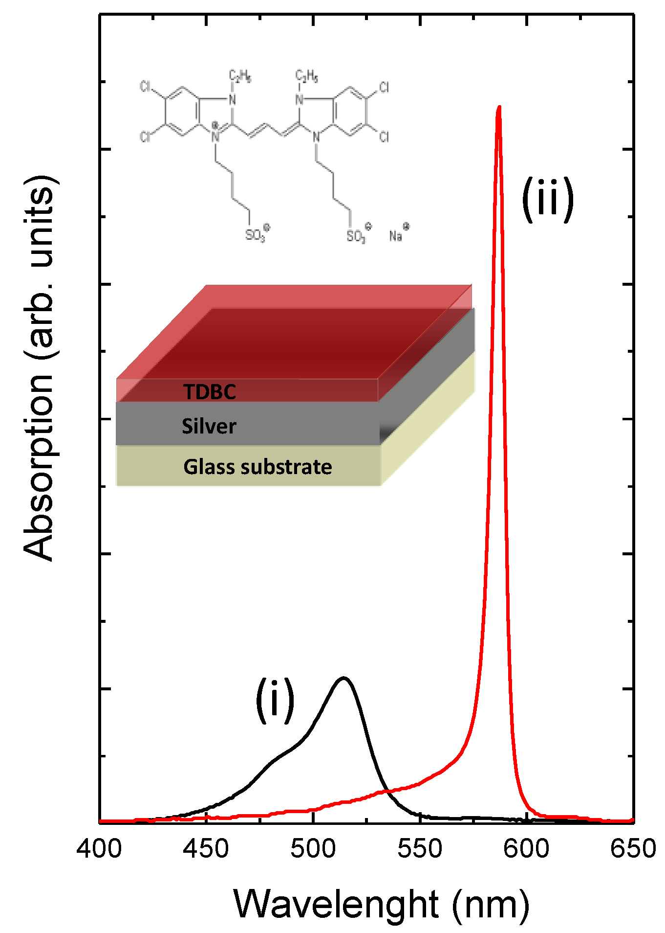
To demonstrate strong coupling between SPs and organic excitons, we used as the active material a J-aggregated cyanine dye (5,5',6,6'-tetrachloro-1,1'-diethyl-3,3'-di(4-sulfobutyl)-benzimidazolocarbocyanine (TDBC)). This material is well suited for the observation of strong coupling due to the aggregation of the monomers that occurs when their concentration in water is sufficient, which induces a redshift and a narrowing of the absorption band.
Figure 1 presents the monomer absorption band of a solution of TDBC diluted in water (i), as well as the J-band of a solution of aggregated TDBC in water (ii). The J-aggregate absorption spectrum is characterized by a single, narrow and intense band lying at about 590 nm (2.1 eV). This band corresponds to the emission of delocalized excitation in the molecular chain, Frenkel excitons. The same optical behavior is observed for a TDBC layer deposited directly on glass (data not shown). The samples studied were constituted of a 45 nm thick silver film produced by thermal evaporation under a pressure of 10
−7 mbar. The active layer (pure TDBC diluted in water) is then spin-coated onto this stack (see inset of
Figure 1).
Figure 1.
Absorption spectra of a solution of (i) TDBC monomer (black line) and (ii) TDBC J-aggregates in water (red line). The inset presents the chemical formula of TDBC and a sketch of a typical sample.
Figure 1.
Absorption spectra of a solution of (i) TDBC monomer (black line) and (ii) TDBC J-aggregates in water (red line). The inset presents the chemical formula of TDBC and a sketch of a typical sample.
In order to investigate the interactions between silver SPs and excitons, reflectometry under the light cone has to be performed. For this purpose, leakage radiation microscopy [
15] or reflectivity in the Kretschmann geometry [
16] can be used. The incident light is coupled to the SP mode when the projection of its wavevector on the silver plane matches the wavevector of the SP located at the silver-active layer interface, resulting in a lack of the reflection intensity at the SP energy. The value of the SP wavevector is
![Electronics 03 00303 i001]()
, where
np is the refractive index of the incident medium and
θ is the incident angle of the light in the prism. The SP energy depends on its wave vector and can be changed by modifying the incident light angle, which enables the SP resonance to be tuned and thus cross the exciton energy.
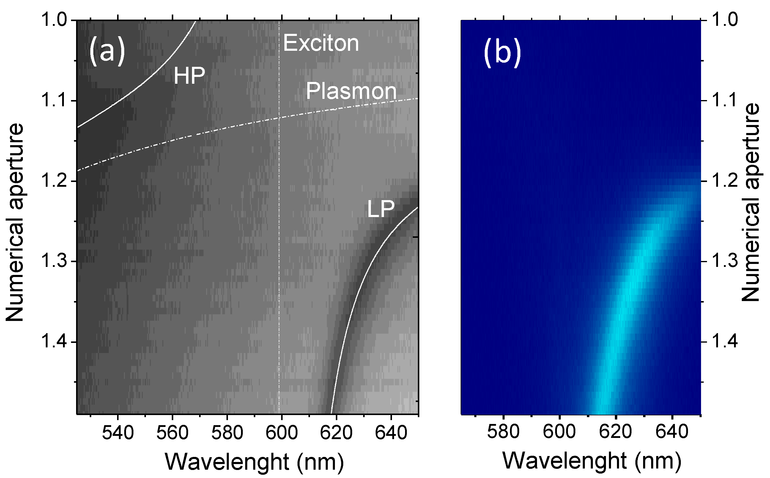
A typical reflectometry image in leakage radiation microscopy is shown in
Figure 2a. In this configuration
![Electronics 03 00303 i002]()
where
N.A. is the numerical aperture of the incident light and is proportional to the sine of the incident angle. It has to be noticed that the
N.A. used here is not the total numerical aperture of the microscope objective but a value characterizing the incident angle of the illumination. Two dispersion lines can be seen on the image, one at high wavelength and one less pronounced at lower wavelength. The polariton energies can be calculated using a coupled oscillator model [
17] (plasmon and excitons),
![Electronics 03 00303 i003]()
where
k is the in-plane wavevector,
EU and
EL the energies of the upper and lower polariton states and
E0 the energy of the TDBC exciton.
Epl(k) is the non interacting plasmon mode energy, calculated using a conventional transfer matrix method with thicknesses of 10 nm for the TDBC layer and 50 nm for the silver film.
Δ is given by the interaction energy between the plasmon and exciton, also called Rabi splitting, and corresponds to the minimum energy separation between the two branches. The solid white lines in
Figure 2a represent the calculated polariton dispersion and the dashed lines the bare plasmon and exciton. A good agreement with experimental data is obtained for a Rabi splitting energy of 300 meV.
Figure 2.
(a) Reflectometry and (b) luminescence spectra of a TDBC layer deposited on a 45 nm silver film, displayed as a function of the wavelength and the numerical aperture (N.A.). The dashed lines in (a) correspond to the bare plasmon and exciton dispersion, and the solid lines to the calculated low energy and high energy polaritonic branches.
Luminescence experiments are then performed by exciting the top side of the sample (the TDBC side) with a 532 nm diode laser, and by collecting the emitted light trough the silver layer using the same high numerical aperture objective than for the reflectometry experiment. The recorded image of the emission dispersion is presented in
Figure 2b. On this image, the intense emission band is clearly related to the emission of the low energy polariton. The emission of the high energy polariton is however not visible. This effect, already reported in the literature, could possibly be attributed to the emission of optical phonons between the two polaritonic branches [
17] or to nonradiative decay of the upper polaritonic states towards uncoupled excitonic states [
12].
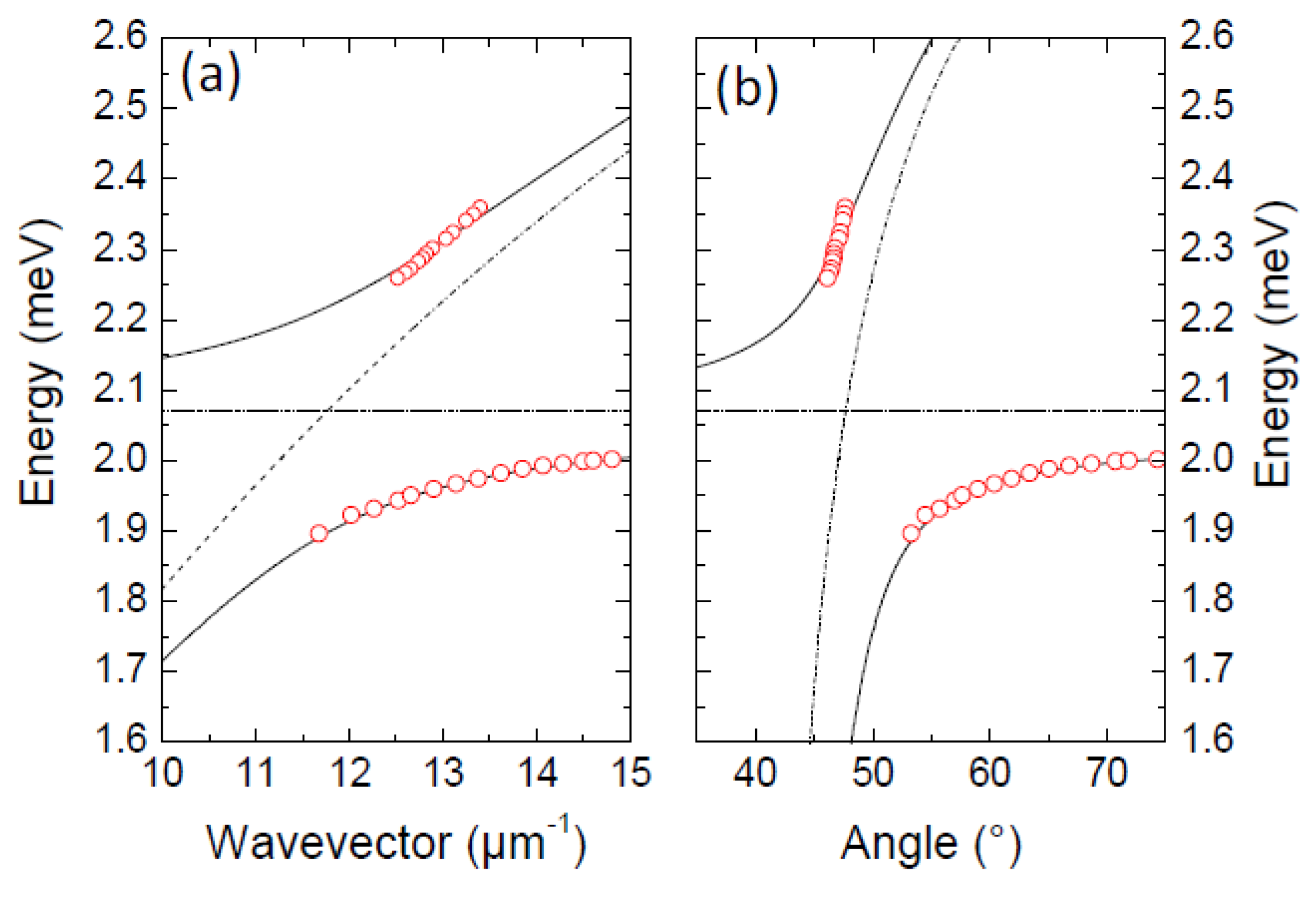
The angle dependence of the polariton energy is more clearly illustrated by the dispersion curves shown in
Figure 3a,b where the calculated energy positions of bare excitons and plasmons are also presented as a function of the wavevector or the angle, respectively. The experimental data present a clear anticrossing between the two lines, characteristic of the strong coupling regime occurring between the SP mode and the TDBC exciton. This strong coupling regime leads to the formation of mixed Plasmon-exciton states, that is to say the high- and low-energy polaritonic branches. It has to be noticed that the minimum energy separation between the hybrid states dispersion lines is not the same if the dispersion energies are shown as a function of the wavevector or the angle (300 meV and 780 meV respectively). The good parameter to qualify the polariton is the wavevector: a plasmon with a given wavevector creates two hybrid states with the same wavevector. This difference between curves in angle or wavevector occurs only for the large energy splitting reached for organics and has not to be taken into account for splitting of a few tens of meV usually obtained for inorganic semiconductors [
18].
Figure 3.
Reflectometry dip energy position (open circles) as a function of (a) the wavevector and (b) the angle. The dashed lines correspond to the calculated bare plasmon and exciton position, the solid lines to the calculated polaritonic branches.
Figure 3.
Reflectometry dip energy position (open circles) as a function of (a) the wavevector and (b) the angle. The dashed lines correspond to the calculated bare plasmon and exciton position, the solid lines to the calculated polaritonic branches.
In addition to the dispersion lines anticrossing, an inversion of the dip linewidths is associated with the strong coupling regime [
19]. At resonance, the polariton states are formed by an admixture of equal weight of plasmon and exciton, and the widths of the two peaks should be the same.
3. Strong Coupling with Localized Plasmons
The values of the Rabi splitting measured for delocalized plasmons in strong coupling with organics reach several hundred of meV. These large values are related to the large oscillator strength of the organic materials as well as the efficient interaction of plasmon spatially confined around the interface. This coupling can be enhanced by using localized plasmons, which present higher spatial confinement of the electric field. This enhanced interaction with localized plasmon has been evidenced in the weak coupling regime, leading to an increase of luminescence [
20], but is also present in strong coupling [
5,
21,
22]. Different geometries have been used like nanoshells or nanorods [
9,
23,
24]. Metallic nanodisks (NDs) made by lithography are also good candidates to study the coupling between organics and localized plasmons [
10,
25]. The main advantage of lithographed structures is that the size of the NDs and their environment (other disks and semiconductor) are well controlled, thereby avoiding a large inhomogeneous broadening of the plasmonic resonances, which could partially mask the plasmon/exciton hybridization. Furthermore, the lithography technique is fully compatible with passive plasmonic devices, such as low-attenuation guides or plasmonic nano cavities developed recently.
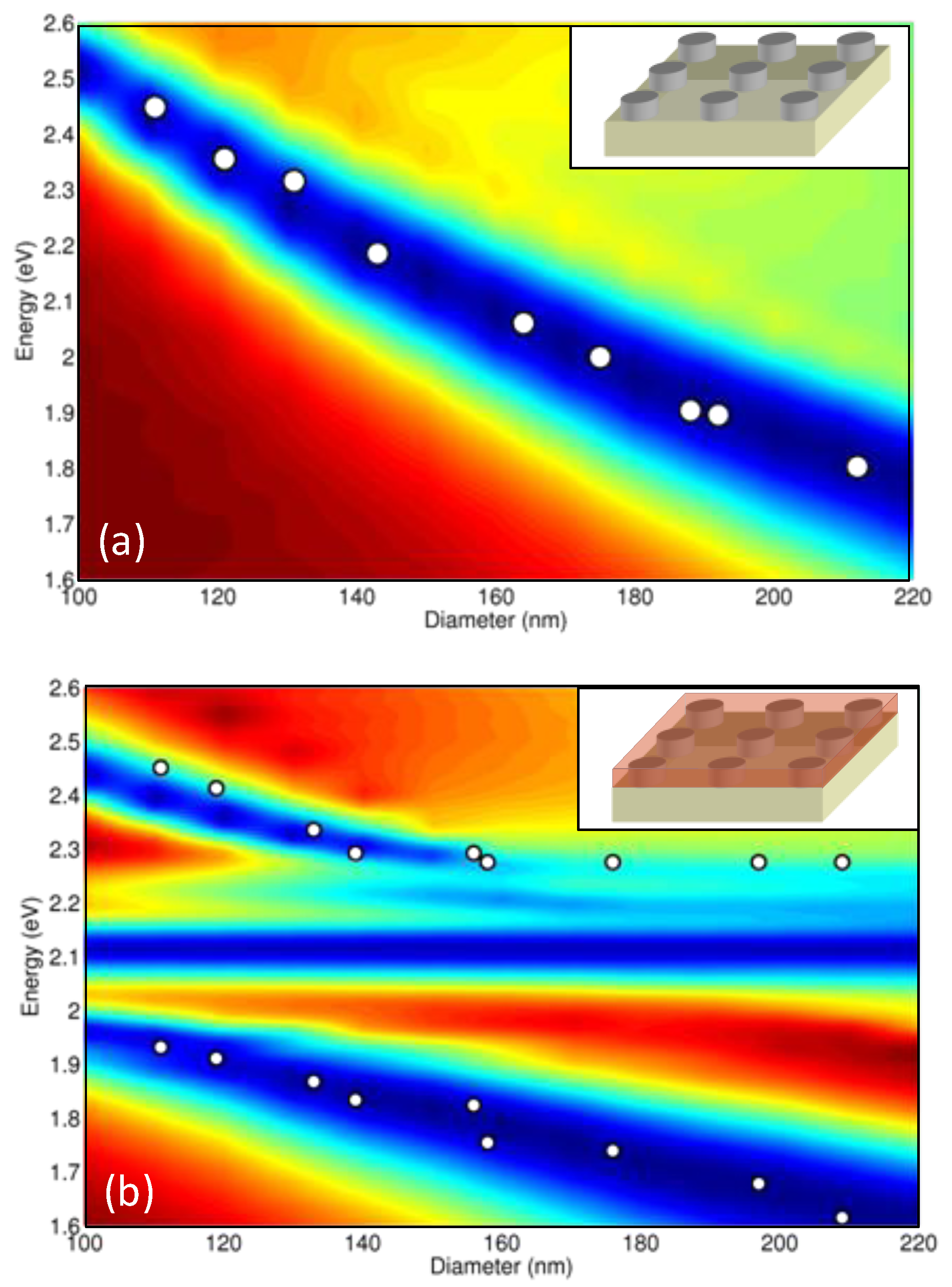
In order to study the interaction between localized surface plasmon (LSP) and J-aggregated dyes, Ag NDs have been elaborated on a glass substrate. For this purpose, circular patterns have been defined on a resist layer by e-beam lithography. A 60 nm thick silver film was evaporated on the lithographed structure, and then removed by the lift-off technique hence revealing the silver ND assemblies on the surface. Each assembly consists of a 200 by 200 µm array made of several tens of thousands of NDs separated by 210 nm side to side. Several arrays, with different ND diameters, were fabricated in order to tune the LSP resonance energy. The ND sizes range from 100 nm to 210 nm.
As the localized plasmon resonance can be directly determined with extinction measurements, transmission experiments were done at room temperature on circular regions (50 µm diameter) probing around 2 × 10
4 identical NDs. A pronounced transmission dip is observed for each array, associated to the ND LSP resonance. When decreasing the ND diameter, this transmission dip experiences an energy blueshift.
Figure 4a shows the experimental variation of the LSP resonance energy as a function of the ND diameter. Transmission spectra were also simulated with 3D FDTD calculations using the silver dielectric constant values reported by Johnson
et al. [
26]
. The calculated spectra are shown in color map in
Figure 4a and present an excellent agreement with the experimental data.
Figure 4.
Measured energy of the transmission dips (white circles) as a function of the disk diameter and 3D FDTD calculated transmission spectra for (a) a bare sample and (b) a sample covered with a TDBC layer.
Figure 4.
Measured energy of the transmission dips (white circles) as a function of the disk diameter and 3D FDTD calculated transmission spectra for (a) a bare sample and (b) a sample covered with a TDBC layer.
To create hybrid localized plasmons/excitons, an active layer of pure TDBC diluted in water was spin coated onto the whole sample surface. The transmission spectra for this sample show two resonances whose energy positions are dependent of the disk diameter, which is summarized in
Figure 4b. A clear anticrossing behavior can be observed in this plot, which is the signature of localized plasmon-exciton strong coupling. For a given disk size, each resonance can thus be associated to a plasmon/exciton mixed state. This result is confirmed by the transmission spectra calculated by 3D FDTD, in which a dye layer of total thickness 22.5 nm has been considered. The calculated and the experimental values are again in excellent agreement. The non dispersive transmission dip lying around 2.1 eV corresponds to the absorption of the uncoupled exciton, originating from the regions between the NDs in which the TDBC cannot interact with the LSP. From
Figure 4a, it can be seen that for ND diameter of about 150 nm the bare plasmon resonance lies at the same energy that the one of the uncoupled excitonic absorption. The minimum energy splitting between the mixed states is obtained for the same ND size in
Figure 4b, leading to an estimated Rabi splitting of 450 meV [
10]. This value amounts to 20% of the transition energy and metal nanodisks can be considered as a model system to study very strong interaction between a single electromagnetic mode and an optically active medium [
27,
28].
4. Influence of Microscopic Disorder of Organics and Plasmon Induced Coherence
In the previous description of the strong coupling regime with organics, the microscopic structure of the organics was not taken into account. From a microscopic point of view, the organic films are formed by an ensemble of localized independent emitters which can be seen as point dipoles as their size is several orders of magnitude smaller than the wavelength.
The molecular film differs from inorganic semiconductor quantum wells as the in plane wavevector is not conserved in absorption-reemission, which is the case for semiconductor quantum wells (excitons center of mass wavevector equals in-plane photon wavevector). The question which arises is how the coherent absorption/reemission, in other word the Rabi oscillation associated to the strong coupling regime, occurs; or how a dispersive plasmon can hybridize with non-dispersive molecules to form dispersive hybrid states. This problem has been addressed by Agranovich
et al. [
12]. They have shown that a coherent state over a large number of molecules is formed in strong coupling regime. The plasmon/excitons hybrid state is a quantum superposition of a photon and excitations on a large number of molecular sites. The extension of the states is directly correlated to the disorder in the organic film and to the losses of the propagating plasmon. From an experimental point of view, the dependence of the Rabi splitting on the concentration of emitters is a good indication of collective effects; however, the coherence of spatially remote emitters induced by hybridization with a plasmon can also be directly observed [
13].
To clearly separate the effect of the plasmon/exciton hybridization from the extension only associated with the plasmon propagation, samples in strong and weak coupling were compared. The active layer of the first sample (sample A) contains a continuous layer of CdSe quantum dots in weak coupling regime (a crossing between plasmon and excitons appears in reflectometry images). The second sample (sample B) contains a TDBC layer on silver and is similar as the sample described in the part 2 (Rabi splitting 300 meV).
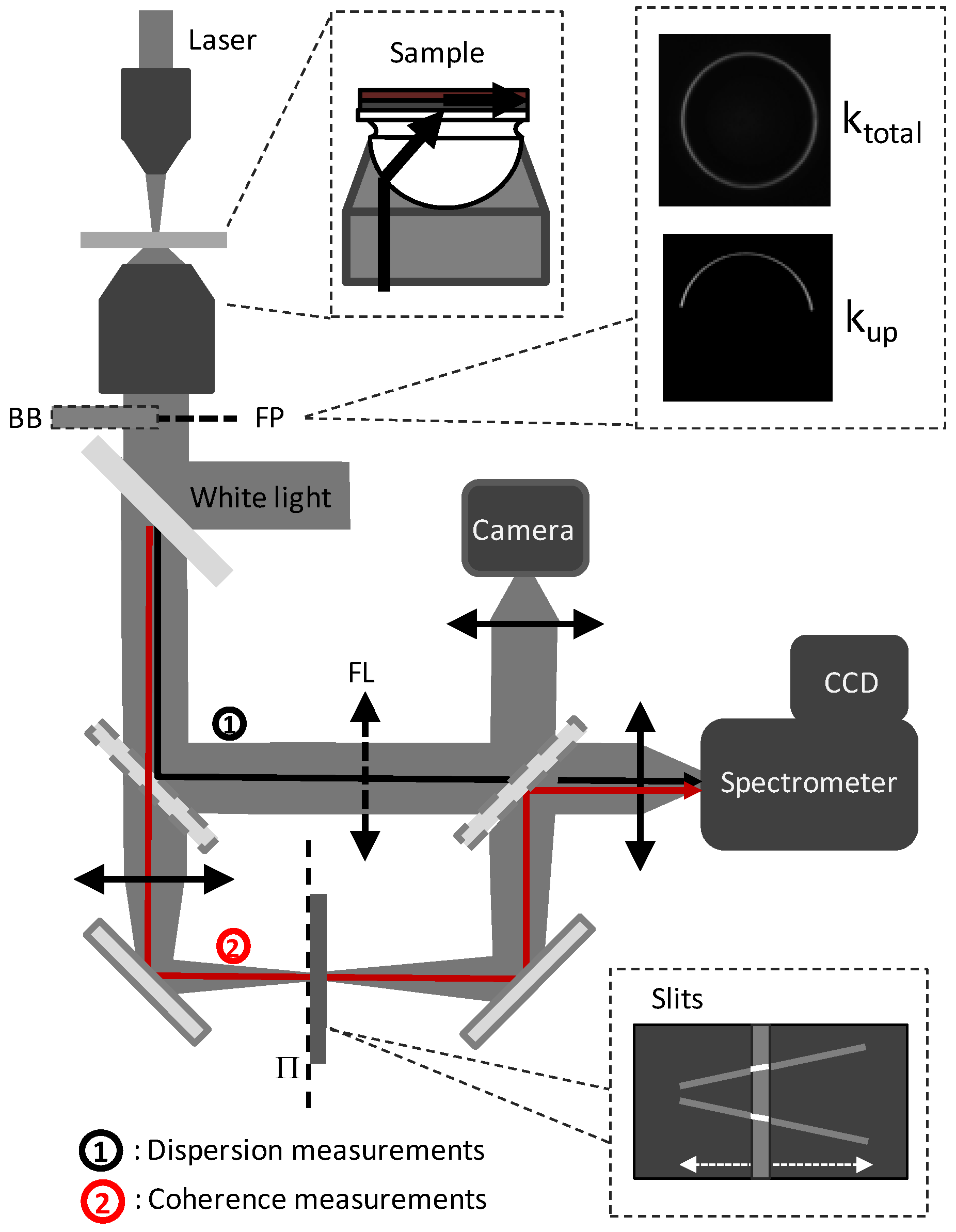
To evidence the formation of the extended state mixing a plasmon and excitation of different molecules, coherence experiments using Young slits have been performed. The leakage radiation (LR) microscopy setup already mentioned in part 2 is detailed in
Figure 5. The sample is excited with a non-resonant laser at 532 nm. The emission is collected through an immersion oil microscope objective (
N.A. = 1.49) and imaged on a CCD camera. On a direct image of the surface, the directions of propagation can be selected by inserting beam block in the Fourier plane of the objective [
29] collecting either all the propagating directions (k
total configuration) or solely the upward propagation as shown in the inset in
Figure 5 (k
up configuration). To analyze the coherence of the emission, two Young slits can be inserted in an intermediate image plane of the sample and select the emission from two regions of the sample separated by a distance of 2 µm.
Figure 5.
Sketch of the leakage radiation microscopy setup. BB denotes the position of the removable beam block, FP the Fourier plane, FL the Fourier lens, and Π the intermediate image plane of the sample surface in which are inserted the Young’s slits. The black line labeled 1 is devoted to dispersion measurements, and the red line labeled 2 to coherence measurements.
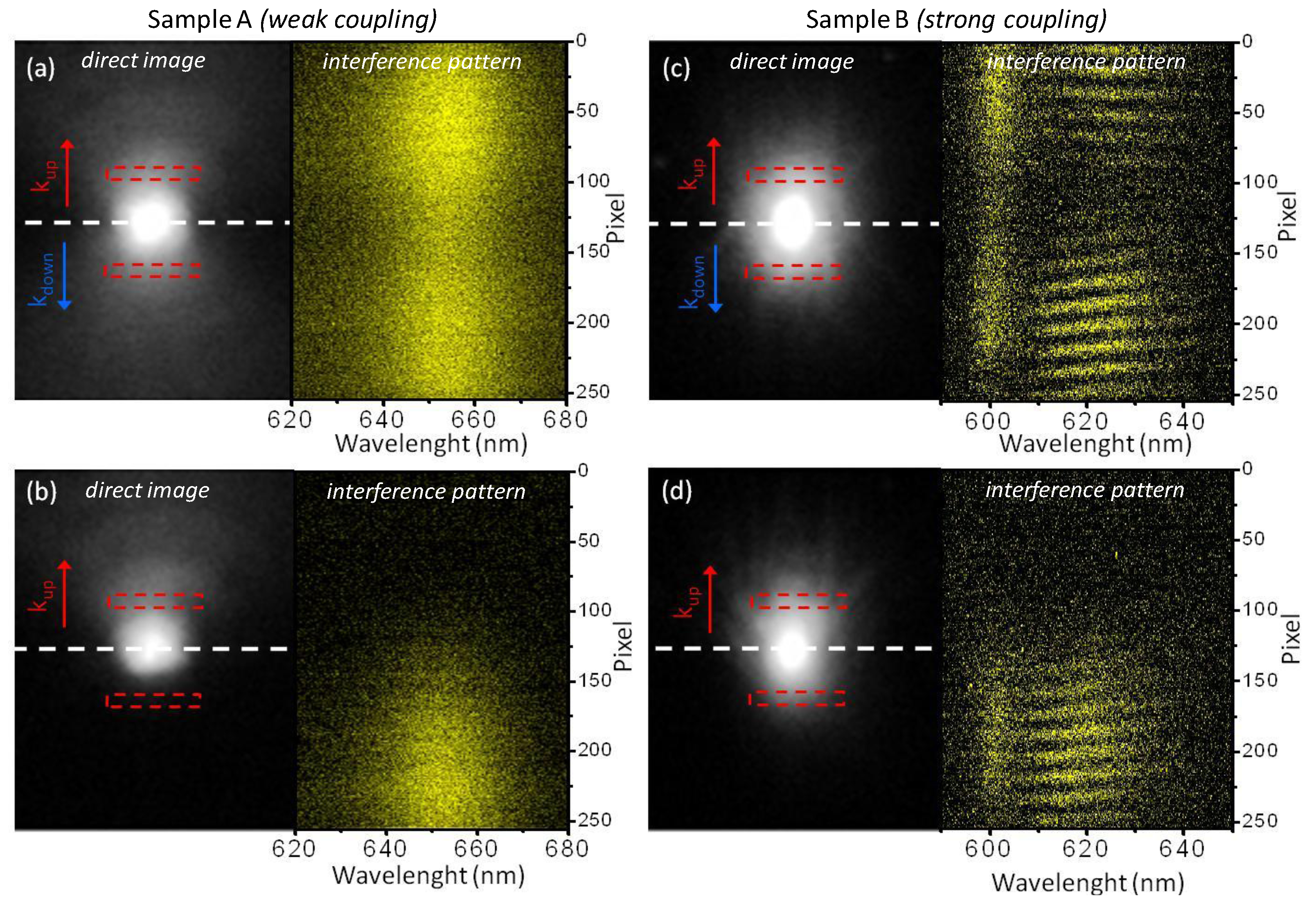
Direct images of the emission as well as the corresponding interference patterns are shown on the left and right side of the panels of
Figure 6a–d. A focalized excitation is used corresponding to the white spot at the center of the direct images, which is smaller than the distance between the Young slits (dashed red rectangles). For the sample A in weak coupling regime an upward and downward propagation appear in the direct Image 6a and only an upward propagation in
Figure 6b where a Fourier beam block was used. This agrees with a mechanism where each emitter in the excitation spot couples independently to plasmons propagating upwards and downwards in
Figure 6a and only upward in
Figure 6b. The corresponding interference patterns do not show any fringes, related to the incoherent emission of the different emitters.
The system in strong coupling regime corresponds to the panels
Figure 6c and
Figure 6d. The shape of the emission in direct images is now similar with
Figure 6c and without
Figure 6d Fourier filtering. This shows that the emission observed cannot be interpreted as a sum of emission of independent molecules coupled to propagating plasmons. In the interference pattern, clear fringes are present showing a coherent emission over all the luminescence spot. These results show a clear collective behavior, and evidence the formation of a coherent state extended on several microns [
13]. In this case the excitation directly relaxes in the extended state with a given wavevector, explaining the large coherent emission spot observed in
Figure 6d.
Figure 6.
Direct imaging of the surface leakage radiation together with the associated interference pattern recorded for two samples: CdSe nanocrystals in weak coupling with the surface plasmon recorded in (a) ktotal and (b) kup detection configuration; TDBC in strong coupling regime with the surface plasmon recorded in (c) ktotal and (d) kup detection configuration.

 , where np is the refractive index of the incident medium and θ is the incident angle of the light in the prism. The SP energy depends on its wave vector and can be changed by modifying the incident light angle, which enables the SP resonance to be tuned and thus cross the exciton energy.
 where N.A. is the numerical aperture of the incident light and is proportional to the sine of the incident angle. It has to be noticed that the N.A. used here is not the total numerical aperture of the microscope objective but a value characterizing the incident angle of the illumination. Two dispersion lines can be seen on the image, one at high wavelength and one less pronounced at lower wavelength. The polariton energies can be calculated using a coupled oscillator model [17] (plasmon and excitons),
  where k is the in-plane wavevector, EU and EL the energies of the upper and lower polariton states and E0 the energy of the TDBC exciton. Epl(k) is the non interacting plasmon mode energy, calculated using a conventional transfer matrix method with thicknesses of 10 nm for the TDBC layer and 50 nm for the silver film. Δ is given by the interaction energy between the plasmon and exciton, also called Rabi splitting, and corresponds to the minimum energy separation between the two branches. The solid white lines in Figure 2a represent the calculated polariton dispersion and the dashed lines the bare plasmon and exciton. A good agreement with experimental data is obtained for a Rabi splitting energy of 300 meV.