PA6 Nanofibre Production: A Comparison between Rotary Jet Spinning and Electrospinning


1
School of Engineering and Materials Science, Queen Mary University of London, Mile End Road, London E1 4NS, UK
2
Faculty of Chemistry and Chemical Engineering, Eindhoven University of Technology, P.O. Box 513, 5600 MB Eindhoven, The Netherlands
3
Nanoforce Technology Ltd, Joseph Priestly Building, Queen Mary University of London, Mile End Road, London E1 4NS, UK
*
Author to whom correspondence should be addressed.
Fibers 2018, 6(2), 37; https://doi.org/10.3390/fib6020037
Submission received: 5 April 2018
/
Revised: 23 May 2018
/
Accepted: 28 May 2018
/
Published: 5 June 2018
Abstract
:Polymer nanofibres are created from many different techniques, with varying rates of production. Rotary jet spinning is a relatively new technique for making nanofibres from both polymer solutions and melt. With electrospinning being by far the most widespread processing method for polymer nanofibres, we performed a direct comparison of polyamide 6 (PA6) nanofibre production between these two methods. It was found that electrospinning produced slightly smaller-diameter fibres, which scaled with a decrease in solution viscosity. In comparison, rotary jet spun fibres could be produced from a reduced range of polymer concentrations and exhibited therefore slightly larger diameters with greater variation. Crystallinity of the fibres was also compared between the two techniques and the bulk polymer, which showed a decrease in crystallinity compared to bulk PA6.

1. Introduction
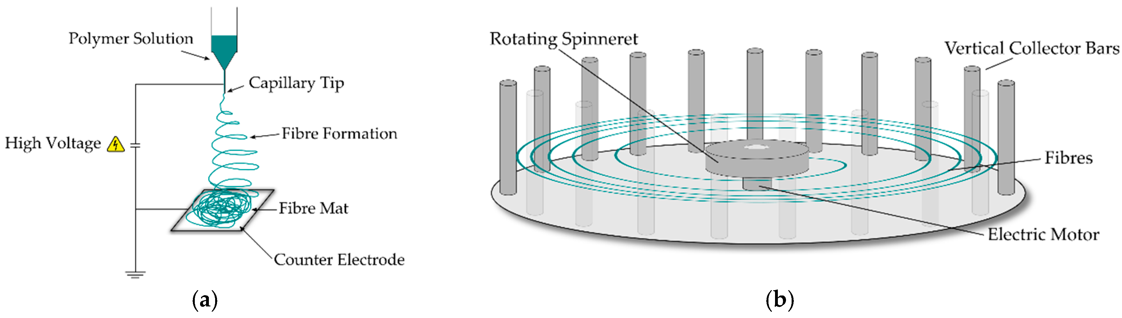
The number of nanofibre-related publications based on rotary jet spinning has increased in recent years following interest surrounding the technology, which was initially developed in Texas, USA, by Lozano et al. [1]. The technology is based around the relatively well-known technique of candy floss production, where a material in the form of a melt or solution is held in a vessel before undergoing rapid rotation, expelling the contents of the vessel through orifices around the perimeter, producing near continuous fibres on a stationary collector as shown in Figure 1. Nanofibre production is the primary aim of this technology, with mass production being the lead driver in further research. Many reviews [2,3,4,5] into nanofibres have been published which investigate ever more uses for these amazing materials from many production methods. The applications that show significant promise for these materials include biomedical applications (drug delivery and tissue engineering scaffolds) [6,7,8,9], energy storage devices (lithium ion batteries) [10,11,12], and also air and water filtration applications [13,14,15]. Polymer nanofibres possess a very high surface area to volume ratio resulting in attractive applications where this property is advantageous. One such application is in drug delivery, where drugs can either be coated onto the fibres or embedded within the fibre before implantation in the body, which results in a slower release and subsequent absorption by the patient over traditional administration methods.
In filtration applications, the morphology can utilise the small pore size in nanofibre mats to filter harmful contaminants from a reduced product size over traditional designs in air filtration. Although the devices are smaller, they have been proven to perform to the same level if not better than HEPA (High Efficiency Particulate Air) standards, filtering 99.993% of particles efficiently at a face velocity of 5 cm/s using 0.3 µm test particles [14]. The issues with this application to date include filter blockage, corresponding with a subsequent pressure drop, which would require cleaning before a similar commercially available product such as a HEPA filter, where products are designed to maximise volumetric flow over time without a reduction in performance.
As most of these applications show promise in a lab environment, the long-standing issue to date in nanofibre production is how upscaling can meet large volume manufacturing needs. Lab-scale nanofibres have been produced from many different techniques such as electrospinning, melt blowing, islands-in-the-sea spinning, template syntheses, drawing, phase separation, self-assembly and more recently, rotary jet spinning [16]. Of these lab-scale devices, only electrospinning, rotary jet spinning, and potentially melt blowing are capable of producing nanofibres on an industrial scale.
Electrospinning is a process that is somewhat different from rotary jet spinning, in that it does not use any mechanical forces to expel or extrude a solution to produce a fibre. Instead, it relies on a high electrostatic charge that is applied between a polymer solution, which is slowly ejected from a needle tip, and a counter electrode to collect the fibre. The attraction of the fibre that is being drawn from the capillary tip depends on a sufficiently high dielectric constant of the solution.
Until now, no direct comparison has been made between rotary jet spinning and electrospinning. In this study, a direct comparison of both spinning processes using one specific polymeric material was carried out under the same laboratory conditions. For this, we investigated nanofibre production of polyamide 6 (PA6) and compared processability and fibre diameters for both methods, along with crystallinity of the resulting fibres.
In rotary jet spinning, there are several variables which can be tuned to produce the required fibre properties, but not all of them have an influence on fibre diameter or bead formation. Processing parameters that have been shown to affect fibre diameter are the concentration of the polymer solution and needle size [17]. In their study, Krifa et al. evaluated the beads on a string phenomenon using PA6 solutions and performed an analysis of variance (ANOVA) to calculate the significance of these variables on the reduction of fibre beading. Early tests by these authors are in agreement and have shown the smallest diameters to not depend on rotational velocities, but instead depend more so on the solution concentration and hence rheological properties of the spinning solutions.
The rate at which nanofibres can be produced varies according to the method and production variables, but can be summarised by concluding that electrospinning is as much as 50 times slower at producing nanofibres compared to rotary jet spinning [16]. Industrial electrospinning machines such as Nanospinner416 by Inovenso Ltd. (Istanbul, Turkey) are capable of producing 210 g h−1 [18], whereas an industrial rotary jet spinning device, the FX2200 by FibeRio (McAllen, TX, USA), can produce up to 12,000 g h−1 [19] from a continuously produced 2.2 m wide nonwoven.
Lab-scale versions of these devices such as those used in this research usually have one or two needles. Electrospinning production rates versus rotary jet spinning in these research sized versions are still orders of magnitude lower, with lab-scale devices producing typically up to 0.11 g h−1 for electrospinning, and up to 60 g h−1 per orifice for rotary jet spinning [20].
It is with this benefit of increased production output that a direct comparison of the same material will be carried out to evaluate the fundamental differences and benefits that come from rotary jet spinning. For example, it might be envisaged that some loss in fibre quality will be observed due to the rapid fibre production rates in rotary jet spinning, compared to that of a more established and controlled process like electrospinning.
2. Materials and Methods
For the PA6 grade chosen, our common control parameter was the polymer concentration in solution (viscosity), which is known to significantly affect spinning behaviour. In our experiments, the electrospinning control parameters included the applied voltage and solution feed rate, whereas rotary jet spinning only included rotational velocity. The collector distance in both experiments was set to 10 cm.
To achieve directly comparable results, an identical polymer grade was used in both electrospinning and rotary jet spinning. PA6 pellets were acquired from Lanxess (Newbury, UK) (Durethan® B31F) (low viscosity, extrusion grade, Mw unavailable), and formic acid (>98%) was purchased from Sigma Aldrich (Gillingham, UK). All materials were used as received.
Polymer concentrations in solution were chosen to produce an array of results from non-fibre producing droplets and beading behaviour through to complete blockage and no fibre production at all. The solutions chosen ranged from 1 wt. % to 30 wt. % polymer concentrations in multiples of 2.5 wt. %.
Prior to solution preparation, the PA6 was dried at 80 °C for 4 h to remove any residual moisture as per manufacturers’ guidelines. Once dried, the solution concentrations were prepared by mixing together the formic acid and PA6 at ambient temperature using a stirring plate and magnetic stirrers. The solutions were stirred for a minimum of 72 h to allow complete dissolution, after which rheological testing was conducted using a rheometer (Discovery Hybrid Rheometer 3) (TA Instruments, New Castle, DE, USA) fitted with a 40 mm plate–plate attachment to evaluate the viscosity at room temperature.
Fibre Production
Electrospinning was conducted using an in-house built setup for all solution samples. The high voltage was produced using a DC power supply (Glassman, High Bridge, NJ, USA) which produced the 15–25 kV DC required, along with a Kent Genie syringe pump which facilitated the polymer solution delivery. Parameters were adjusted to find the most appropriate values for each solution sample for high fibre yield without visible droplets. A needle with an internal diameter of 600 µm was placed 10 cm from the collector plate, with applied voltage and volumetric feed rates varied according to Table 1.
Rotary jet spinning was performed using a FibeRio Cyclone L-1000D lab-scale device (FibeRio, McAllen, TX, USA). A solution spinning setup was installed with a radial collector used to “catch” the fibres as they were spun. The solution spinneret contains two needles (160 µm internal diameter) to spin the fibres, with collector bars placed at 10 cm from the needle outlet. Variations of the angular velocity were studied to select the most appropriate values for spinning, and are shown in Table 1.
3. Results
3.1. Solution Characterization
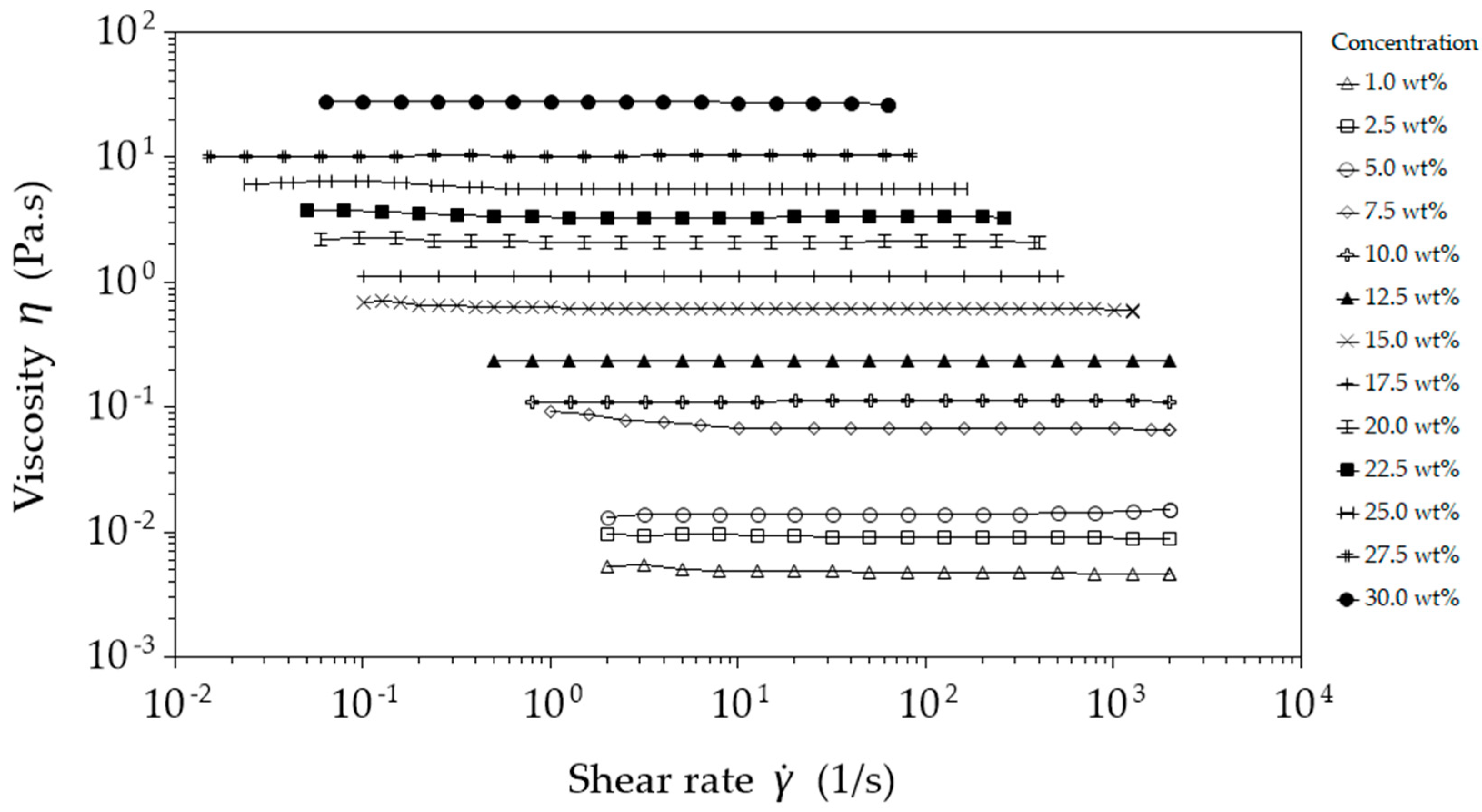
The viscosity of the solutions shown in Figure 2 shows characteristic Newtonian flow behaviour, with values ranging from 4.6 mPa·s to 27.7 Pa·s for 1 wt. % and 30 wt. %, respectively. The solutions exhibit a steep increase in viscosity at a polymer concentration of 7.5 wt. %, where molecular chain entanglement (Me) starts to increase, and sufficient chain overlap develops to introduce viscoelastic effects in what has been termed the concentrated regime by Tsou et al. [21,22].
According to Tsou et al., the concentration of the polymer within the solvent will produce three distinct phases of rheological behaviour. According to their work, these phases are (a) semi-dilute disentangled regime, (b) semi-dilute entangled regime, and (c) concentrated entangled regime. In the solutions prepared for this study and shown in Figure 3, we have the latter two regimes. It is in these regimes that fibres can start to be spun via both electrospinning and rotary jet spinning.
The surface tension of the three solution concentrations was measured by pendant drop analysis using a DSA100 (KRÜSS GmbH, Hamburg, Germany) to evaluate the variation of surface tension with concentration. The chosen samples were 15 wt. %, 20 wt. %, and 25 wt. %. The surface tension of formic acid is known to be 37.7 mN·m−1, however with the inclusion of PA6, a small reduction in the surface tension was found. The three PA6 solution samples measured on average 34.1 ± 0.3 mN·m−1.
3.2. Fibre Characterization
Samples were collected on aluminium foil and oven dried at 70 °C until their weight had plateaued to remove any residual formic acid from the fibres. Once dried, the fibre morphology was investigated using a scanning electron microscope (JSM-6300F) (JEOL Ltd., Tokyo, Japan), where multiple images at set magnifications were obtained.
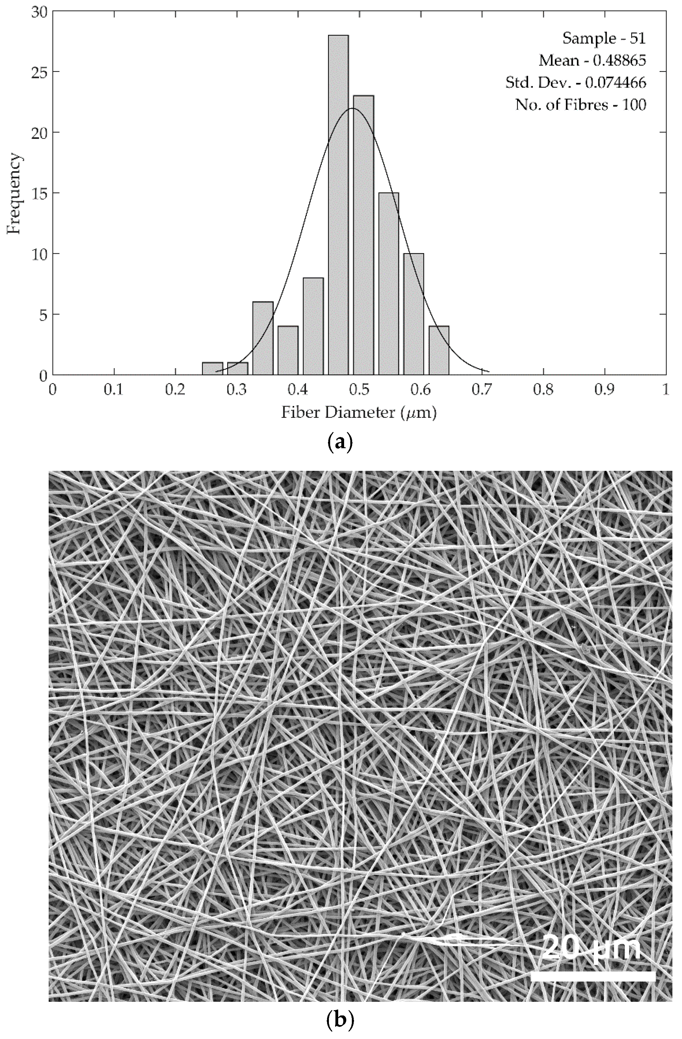
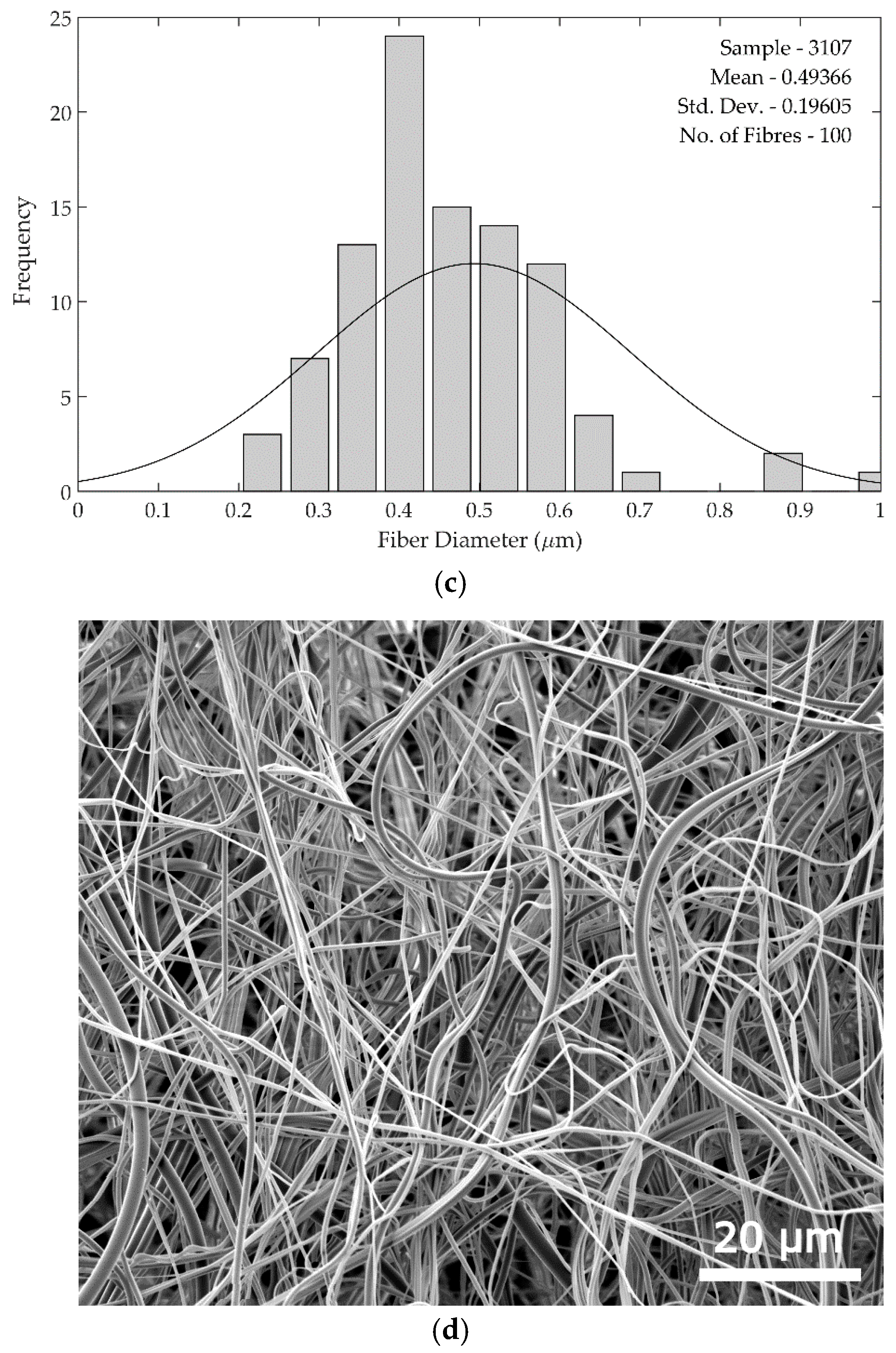
Fibre diameters were measured in batches of 100 sample measurements using ImageJ software (ImageJ version 1.48) (National Institute of Health, Bethesda, MD, USA), and compared as shown in Figure 4. The standard deviations of the fibre diameters are larger in the rotary jet spun samples compared to the electrospun samples, as can be seen from the histograms in Figure 5. The increased standard deviation from the rotary jet spun fibres is common in this process due to the uncontrolled and chaotic deposition of the fibres.
The deposition process in rotary jet spinning is chaotic due to the spinning reservoir creating significant amounts of air turbulence from the fast-moving spinning head, which the fibres are required to negotiate before coming to rest. This leads to a larger variation in diameters due to the way in which the fibres settle on one another in the current laboratory setup, which utilised a radial collector as illustrated in Figure 1. Conversely, the fibre deposition in electrospinning is done systematically by a constant electrostatic force without much interference from air turbulence, which resulted in the fibre deposition attaining an equilibrium, delivering relatively similar fibre diameters throughout deposition as shown in Table 2.
Visually, the fibres in the rotary jet spun samples were much less compact and often collected in such a way that resulted in a reduction in the collector distance as the fibres formed a 3D network of attachments. A reduction in the collector distance due to this 3D network seemed to slowly increase the fibre diameters as they had less space to be drawn before becoming stationary. Given sufficient time, this reduces to no gap at all where the rotating needles will catch the previously formed nanofibres and pull them from the radial collector. Zander et al. have shown a slight increase in diameter with a reduction in collector distance to illustrate this point somewhat [23].
Figure 5 shows SEM images and fibre diameter data for the 22.5 wt. % spinning solution used for both methods. In the histograms, the curve clearly shows a larger standard deviation in rotary jet spun fibre diameters. This larger diameter variation was seen across all rotary jet spun fibres produced compared with those from electrospinning.
At the lowest viscosities, both spinning methods did not produce fibres, but instead produced droplets of solution containing PA6 as seen in Figure 6. Upon deposition on the collector surface, the low polymer concentration solutions produced a coating following the evaporation of formic acid. Electrospinning produced continuous fibres from 7.5 wt. % to 25 wt. %, whereas rotary jet spinning only produced fibres from 17.5 wt. % to 25 wt. %, after which no fibres were produced from either method due to nozzle blockage.
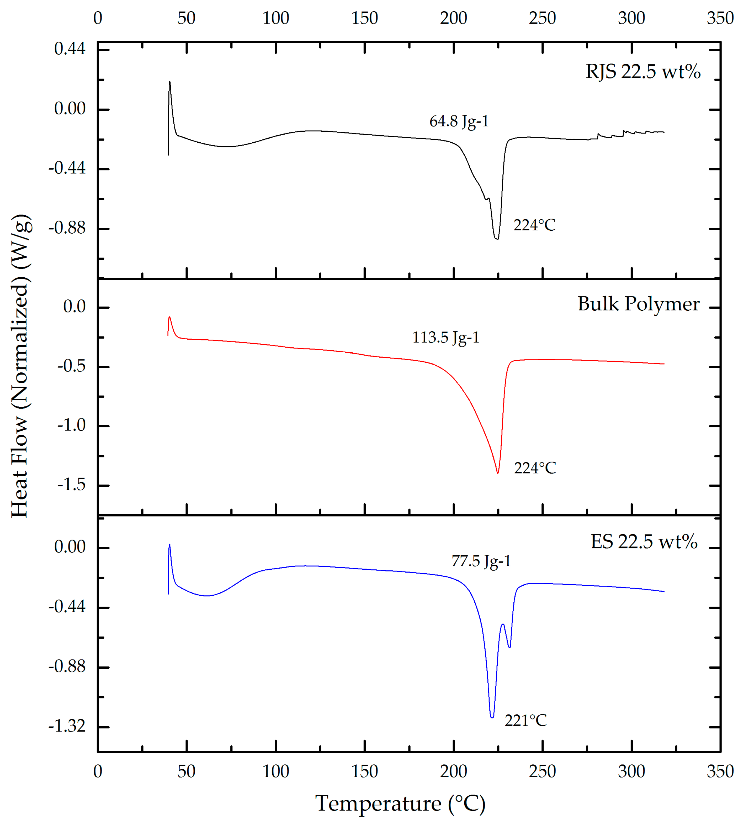
Differential scanning calorimetry (DSC) was performed using a DSC 25 (TA Instruments, New Castle, DE, USA) for evaluation of fibre crystallinity. Samples were heated from 30 °C to 320 °C at 10 °C min−1, held isothermally for 5 min before cooling at 10 °C min−1 to 30 °C. Figure 7 shows a comparison of DSC heat traces from the initial thermal ramp for 22.5 wt. % solution spun fibres and bulk PA6.
Sample crystallinity () was evaluated using Equation (1), where the observed enthalpy () could be calculated by integrating the peak values from the DSC heat traces. The enthalpy of fusion () is taken to be 230 J g−1 for 100% crystalline PA6 as per the suggested value by Wunderlich [24]. With this reference value, the crystallinity of all samples could be compared from the bulk polymer to the electrospun and rotary jet spun fibres.
As seen in Table 3, it is clear that the percentage of crystallinity in the produced nanofibres is lower than that of the bulk polymer, with a crystallinity difference of over 10% after fibre processing. This difference in crystallinity is an outcome of the method by which crystal growth occurs during the bulk processing of PA6 pellets, where slower melt cooling promotes increased α-form crystal growth, versus the rapid solution evaporation that occurs in fibre formation where rapid γ-form crystal growth can produce a polymer with much less of a crystal structure [25].
4. Discussion
In this study, we set out to evaluate the difference in fibre morphology, crystallinity, and production rates between electrospinning and rotary jet spinning. In the case of electrospinning, well-formed fibres were produced without beading between a polymer in solution range of 10 wt. % to 22.5 wt. %, where at 25 wt. % the fibres became ribbon-like. In contrast to this, the rotary jet spun samples produced fibres from 17.5 wt. % to 25 wt. % polymer concentrations in solution, although all but the 25 wt. % fibres showed some level of beading. Electrospun fibre diameters increased throughout, overlapping with rotary jet spun fibres at 22.5 wt. % (3.3 Pa·s).
Above 22.5 wt. % polymer concentration in solution, the rotary jet spun fibre diameters remained below 1 µm, whereas in the case of electrospinning the fibre diameter almost doubled to 1.3 µm. This would indicate a significant change in the ability of the electrostatic field to attract the polymer solution from the capillary tip in which it no longer produces a cylindrical fibre. The benefit of the solution leaving the rotary jet needle is that it does not have to overcome any electrostatic charge, as it relies solely on centrifugal force and hydrostatic force to expel it. Using a 30 Ga (Internal diameter 160 µm) needle reduced the solution viscosity range that is capable of being spun, which resulted in a blockage of solution concentrations greater than 25 wt. %.
Observations between the spinning methods accounts for some of the fibre diameter variations measured. The range of solution concentrations which can form fibres in electrospinning was shown to be larger, possibly due to the slower volumetric flow rate which allows the solvent to evaporate over a longer period of time during the spinning process. By having a lower volumetric flow rate, electrospinning ensures that the solvent is exposed to the air for longer from the point of solution ejection to polymer fibre collection, compared with rotary jet spinning. This speed differential in electrospinning increases its potential to produce fibres from lower polymer concentrations.
Evaporation rates of the solvent during fibre formation would therefore be a significant contributor to the overall fibre diameter in both processes. During rotary jet spinning, the needle tip is moving at velocities between 40–75 m/s, where the evaporation rate is higher compared to electrospinning, due to the faster moving air over the fibre surface.
This variation in fibre diameters points to a production capability distinction. Smaller fibre diameters are capable of being produced from an electrospinning lab set-up to a point at which rotary jet spinning will produce a smaller diameter fibre—in the current system, this is at 22.5 wt. % polymer in solution concentration. This key distinction would lead to either a choice for speed or fibre diameter in which rotary jet spinning would be favourable in terms of speed, while electrospinning would be favoured in terms of fibre diameter and uniformity of fibres produced. With electrospinning producing fibre at a rate of up to 50 times slower than rotary jet spinning, it is prudent to evaluate the requirements of a smaller diameter fibre over the time required to produce it. Electrospinning and rotary jet spinning apparatus, when scaled to industrial-size units, could potentially see an alternative evidence as to the specific fibre morphology, but this is data not available in this study, which is conducted using lab-scale devices.
The crystallinity of the samples was evaluated using DSC, which is one of the easiest and most widely used methods of determining crystallinity [26]. Heat enthalpy of 100% crystalline PA6 was used to calculate the degree of crystallinity in the fibres based on the integration of the heat enthalpy peaks in the samples. Surprisingly, very little difference is seen between the electrospun samples with an average of 33% crystallinity versus those of the rotary jet spun fibres at an average of 30%. The bulk polymer had a crystallinity of 49%, which is in the region of what is expected for a semi-crystalline PA6.
Nylon 6 consists of two crystal forms, namely α-and γ-forms. The percentages of each form that contributes to the crystalline phase of the polymer depends on processing conditions and rate of their formation. α-Form crystals are typically associated with slow crystallization and are formed from extended PA6 chains, whereas γ-form crystals are produced from rapid crystallization from pleated PA6 chains [25]. The total crystallization percentage of each process, including that of the bulk polymer, can therefore be attributed to the rate of crystallization as well as the processing conditions. In our study, the solution formed nanofibres from electrospinning and rotary jet spinning could have more γ-form crystal structures than α-form structures, and vice-versa for the slower crystal forming method of bulk melt processed PA6 pellets. Electrospun fibres could potentially contain more α-form crystal structures compared to rotary jet spun fibres due to the slower crystal structure formation time vs. rotary jet spinning time, which is known to produce fibres much more rapidly. This increased quantity of both types of crystal structures in electrospun fibres would result in a higher enthalpy, which is seen in Figure 7.
The degree of crystallinity will affect mechanical properties such as the elastic modulus and fracture toughness of these fibres [27], however this was not the focus of this study. Crystallinity within the fibre can also have a dependence on the age of the solvent due to the continued degradation of the polymer chains in the formic acid over time. A study by Nam et al. [28], for example, has shown that electrospun PA6 fibres had differing amounts of crystallinity from the same solvent after four consecutive weeks of trial. However, all samples in the current study were used within a week of each other.
5. Conclusions
In this comparative study, we have set out to establish a direct comparison of creating polymer nanofibres by electrospinning and a relatively new technique called rotary jet spinning. Rotary jet spinning, being a significantly faster method of creating fibres at the nanoscale, could prove a very useful technique for industrial scale production of polymer nanofibres. Fibres were formed from both methods from PA6 solutions in formic acid, and characterised based on their dimensions, spinnability, and crystallinity.
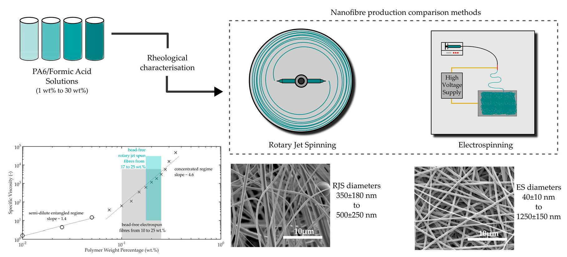
Results showed that although rotary jet spinning can produce fibres faster than electrospinning, the morphology of those fibres was different in average diameter over the whole spectrum of solution concentrations examined. Up to a polymer in solution concentration of 22.5 wt. %, electrospun fibres had slightly smaller diameters which ranged from 40 ± 10 nm to 1250 ± 150 nm, after which point rotary jet spinning produced fibres that measured the smallest diameter at an equivalent polymer solution concentration of 25 wt. % compared with that of electrospinning. Rotary jet spun fibres produced fibres in a narrower polymer concentration range with fibre diameters ranging between 350 ± 180 nm to 500 ± 250 nm.
The crystallinity of the fibres measured showed that the change in crystallinity from bulk PA6 was similar for both fibre production methods, with the bulk polymer having a crystallinity of 49%, being reduced to 33% and 30% for electrospun and rotary jet spun fibres, respectively.
Author Contributions
J.J.R., C.W.M.B. and T.P. conceived and designed the experiments; J.J.R. performed the experiments; J.J.R. analysed the data; J.J.R., C.W.M.B. and T.P. wrote the paper.
Acknowledgments
This work was partly supported by the UK Engineering and Physical Sciences Research Council (EPSRC) grant 1502193 for Queen Mary University of London. The authors also greatly acknowledge the financial support provided by DSM, The Netherlands.
Conflicts of Interest
The authors declare no conflict of interest.
References
- Sarkar, K.; Gomez, C.; Zambrano, S.; Ramirez, M.; de Hoyos, E.; Vasquez, H.; Lozano, K. Electrospinning to forcespinning (tm). Mater. Today 2010, 13, 12–14. [Google Scholar] [CrossRef]
- Ramakrishna, S.; Fujihara, K.; Teo, W.-E.; Yong, T.; Ma, Z.; Ramaseshan, R. Electrospun nanofibers: Solving global issues. Mater. Today 2006, 9, 40–50. [Google Scholar] [CrossRef]
- Ramakrishna, S.; Jose, R.; Archana, P.S.; Nair, A.S.; Balamurugan, R.; Venugopal, J.; Teo, W.E. Science and engineering of electrospun nanofibers for advances in clean energy, water filtration, and regenerative medicine. J. Mater. Sci. 2010, 45, 6283–6312. [Google Scholar] [CrossRef]
- Stojanovska, E.; Canbay, E.; Pampal, E.S.; Calisir, M.D.; Agma, O.; Polat, Y.; Simsek, R.; Gundogdu, S.; Akgul, Y.; Kilic, A. A review on non-electro nanofibre spinning techniques. RSC Adv 2016, 6, 83783–83801. [Google Scholar] [CrossRef]
- Peijs, T. Electrospun polymer nanofibers and their composites. In Comprehensive Composite Materials II; Elsevier: New York, NY, USA, 2018; Volume 6, pp. 162–200. [Google Scholar]
- Buzgo, M.; Rampichova, M.; Vocetkova, K.; Sovkova, V.; Lukasova, V.; Doupnik, M.; Mickova, A.; Rustichelli, F.; Amler, E. Emulsion centrifugal spinning for production of 3D drug releasing nanofibres with core/shell structure. RSC Adv. 2017, 7, 1215–1228. [Google Scholar] [CrossRef] [Green Version]
- Amalorpava Mary, L.; Senthilram, T.; Suganya, S.; Nagarajan, L.; Venugopal, J.; Ramakrishna, S.; Giri Dev, V.R. Centrifugal spun ultrafine fibrous web as a potential drug delivery vehicle. Express Polym. Lett. 2013, 7, 238–248. [Google Scholar] [CrossRef]
- Wang, L.; Chang, M.-W.; Ahmad, Z.; Zheng, H.; Li, J.-S. Mass and controlled fabrication of aligned PVP fibers for matrix type antibiotic drug delivery systems. Chem. Eng. J. 2016, 307, 661–669. [Google Scholar] [CrossRef]
- Barnes, C.P.; Sell, S.A.; Boland, E.D.; Simpson, D.G.; Bowlin, G.L. Nanofiber technology: Designing the next generation of tissue engineering scaffolds. Adv. Drug Deliv. Rev. 2007, 59, 1413–1433. [Google Scholar] [CrossRef] [PubMed]
- Nava, R.; Cremar, L.D.; Agubra, V.; Sanchez, J.; Alcoutlabi, M.; Lozano, K. Centrifugal spinning: An alternative for large scale production of silicon-carbon composite nanofibers for lithium ion batteries anodes. ACS Appl. Mater. Interfaces 2016, 8, 29356–29372. [Google Scholar] [CrossRef] [PubMed]
- Agubra, V.A.; Zuniga, L.; De la Garza, D.; Gallegos, L.; Pokhrel, M.; Alcoutlabi, M. Forcespinning: A new method for the mass production of sn/c composite nanofiber anodes for lithium ion batteries. Solid State Ion. 2016, 286, 72–82. [Google Scholar] [CrossRef]
- Weng, B.C.; Xu, F.H.; Alcoutlabi, M.; Mao, Y.B.; Lozano, K. Fibrous cellulose membrane mass produced via forcespinning® for lithium-ion battery separators. Cellulose 2015, 22, 1311–1320. [Google Scholar] [CrossRef]
- Liu, C.; Hsu, P.C.; Lee, H.W.; Ye, M.; Zheng, G.; Liu, N.; Li, W.; Cui, Y. Transparent air filter for high-efficiency PM2.5 capture. Nat. Commun. 2015, 6, 6205. [Google Scholar] [CrossRef] [PubMed] [Green Version]
- Ahn, Y.C.; Park, S.K.; Kim, G.T.; Hwang, Y.J.; Lee, C.G.; Shin, H.S.; Lee, J.K. Development of high efficiency nanofilters made of nanofibers. Curr. Appl. Phys. 2006, 6, 1030–1035. [Google Scholar] [CrossRef]
- Yoon, K.; Hsiao, B.S.; Chu, B. Functional nanofibers for environmental applications. J. Mater. Chem. 2008, 18, 5326–5334. [Google Scholar] [CrossRef]
- Rogalski, J.J.; Bastiaansen, C.W.M.; Peijs, T. Rotary jet spinning review—A potential high yield future for polymer nanofibres. Nanocomposites 2017, 3, 97–121. [Google Scholar] [CrossRef]
- Krifa, M.; Hammami, M.A.; Wu, H. Occurrence and morphology of bead-on-string structures in centrifugal forcespun PA6 fibers. J. Text. Inst. 2015, 106, 284–294. [Google Scholar] [CrossRef]
- Industrial Electrospinning Nanofiber Machine | Inovenso, Innovative Engineering Solutions. Available online: http://inovenso.com/portfolio-view/nanospinner416/ (accessed on 29 June 2017).
- Fiber Engine fx Series Systems from Fiberio. Available online: http://www.filtsep.com/view/40670/fiber-engine-fx-series-systems-from-fiberio/ (accessed on 29 June 2017).
- Padron, S.; Fuentes, A.; Caruntu, D.; Lozano, K. Experimental study of nanofiber production through forcespinning. J. Appl. Phys. 2013, 113, 9. [Google Scholar] [CrossRef]
- Tsou, S.Y.; Lin, H.S.; Wang, C. Studies on the electrospun Nylon 6 nanofibers from polyelectrolyte solutions: 1. Effects of solution concentration and temperature. Polymer 2011, 52, 3127–3136. [Google Scholar] [CrossRef]
- Tsou, S.-Y.; Lin, H.-S.; Cheng, P.-J.; Huang, C.-L.; Wu, J.-Y.; Wang, C. Rheological aspect on electrospinning of Polyamide 6 solutions. Eur. Polym. J. 2013, 49, 3619–3629. [Google Scholar] [CrossRef]
- Zander, N.E. Formation of melt and solution spun polycaprolactone fibers by centrifugal spinning. J. Appl. Polym. Sci. 2015, 132, 9. [Google Scholar] [CrossRef]
- Wunderlich, B. Equilibrium melting. In Macromolecular Physics; Academic Press: San Diego, CA, USA, 1980; Volume 3, pp. 1–127. [Google Scholar]
- Liu, Y.; Cui, L.; Guan, F.; Gao, Y.; Hedin, N.E.; Zhu, L.; Fong, H. Crystalline morphology and polymorphic phase transitions in electrospun nylon 6 nanofibers. Macromolecules 2007, 40, 6283–6290. [Google Scholar] [CrossRef] [PubMed]
- Millot, C.; Fillot, L.-A.; Lame, O.; Sotta, P.; Seguela, R. Assessment of Polyamide-6 crystallinity by DSC. J. Therm. Anal. Calorim. 2015, 122, 307–314. [Google Scholar] [CrossRef]
- Bessell, T.J.; Hull, D.; Shortall, J.B. The effect of polymerization conditions and crystallinity on the mechanical properties and fracture of spherulitic Nylon 6. J. Mater. Sci. 1975, 10, 1127–1136. [Google Scholar] [CrossRef]
- Nam, K.-T.; Pant, H.R.; Jeong, J.-W.; Pant, B.; Kim, B.-I.; Kim, H.-Y. Solvent degradation of Nylon-6 and its effect on fiber morphology of electrospun mats. Polym. Degrad. Stab. 2011, 96, 1984–1988. [Google Scholar] [CrossRef]
Figure 1.
Schematics of electrospinning (a) and rotary jet spinning (b); identifying key components from each technique in the production of nanofibres. The key difference is in the high voltage required by electrospinning to attract a fibre by drawing it from an oppositely charged capillary tip, whereas rotary jet spinning uses a mechanical force to eject polymer fibres from a fast-moving spinneret.

Figure 2.
Viscosity data from plate–plate rheometry, showing Newtonian flow behaviour for polymer concentrations ranging from 1 wt. % to 30 wt. %.
Figure 2.
Viscosity data from plate–plate rheometry, showing Newtonian flow behaviour for polymer concentrations ranging from 1 wt. % to 30 wt. %.

Figure 3.
Plot of specific viscosity versus PA6 concentration. The plot shows the transition from semi-dilute entangled regime to concentrated entangled regime, where fibre production starts in electrospinning (>10 wt. %) and rotary jet spinning (>17 wt. %). Specific viscosity is defined as where η represents the solution viscosity and η0 the solvent viscosity.
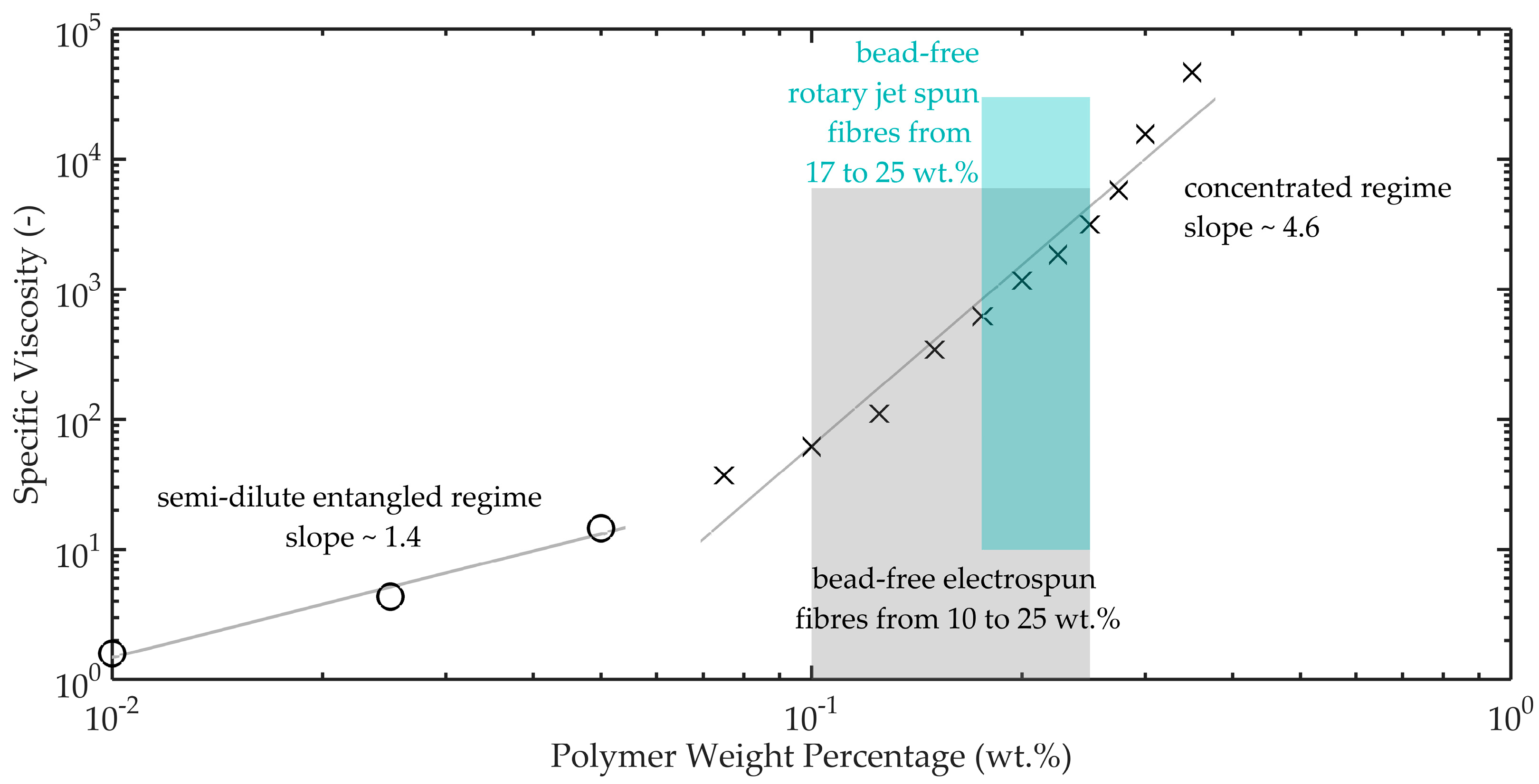
Figure 4.
PA6 fibre diameters from electrospinning (Top) and rotary jet spinning (Bottom), showing the diameters of fibres produced in relation to solution concentration. The range of solutions capable of fibre production is lower for rotary jet spinning than for electrospinning due to the rate of solution evaporation within the process, which results in electrospinning producing fibres from effectively lower polymer concentrations.
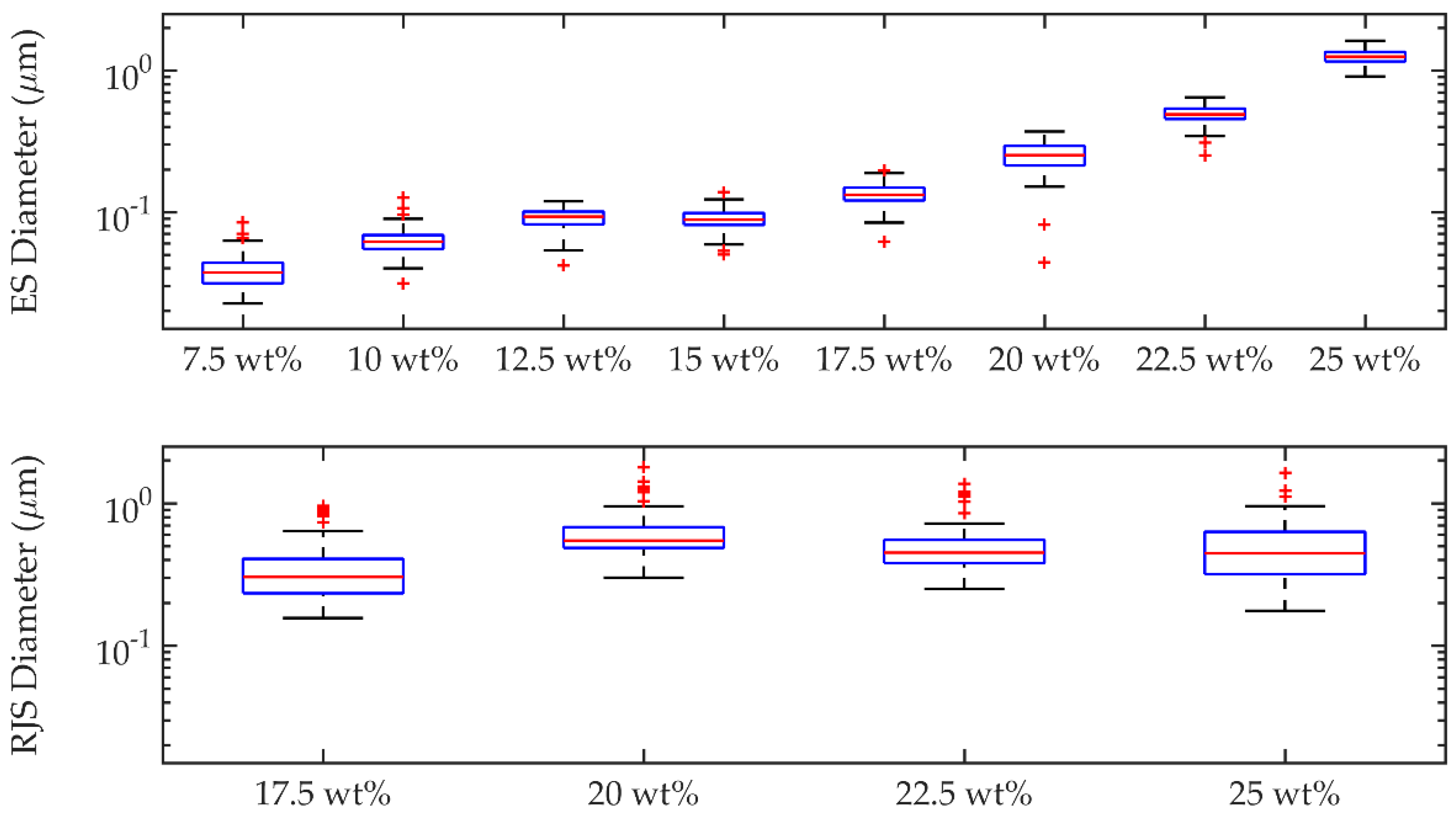
Figure 5.
Nanofibre histograms and SEM images from 22.5 wt. % PA6/formic acid solution using (a,b) electrospinning and (c,d) rotary jet spinning, showing a larger standard deviation for rotary jet spun fibres. The rapid production of rotary jet spinning in the lab scale device produces a more 3D deposition of fibres compared with the typical 2D morphology for electrospinning.


Figure 6.
Scanning Electron Microscopy (SEM) of PA6 fibres produced from electrospinning (Left) and rotary jet spinning (Right). The images show the variation in fibre morphology between the two methods, with electrospinning producing less beaded fibres, including the benefit of fibre production over a wider viscosity range.
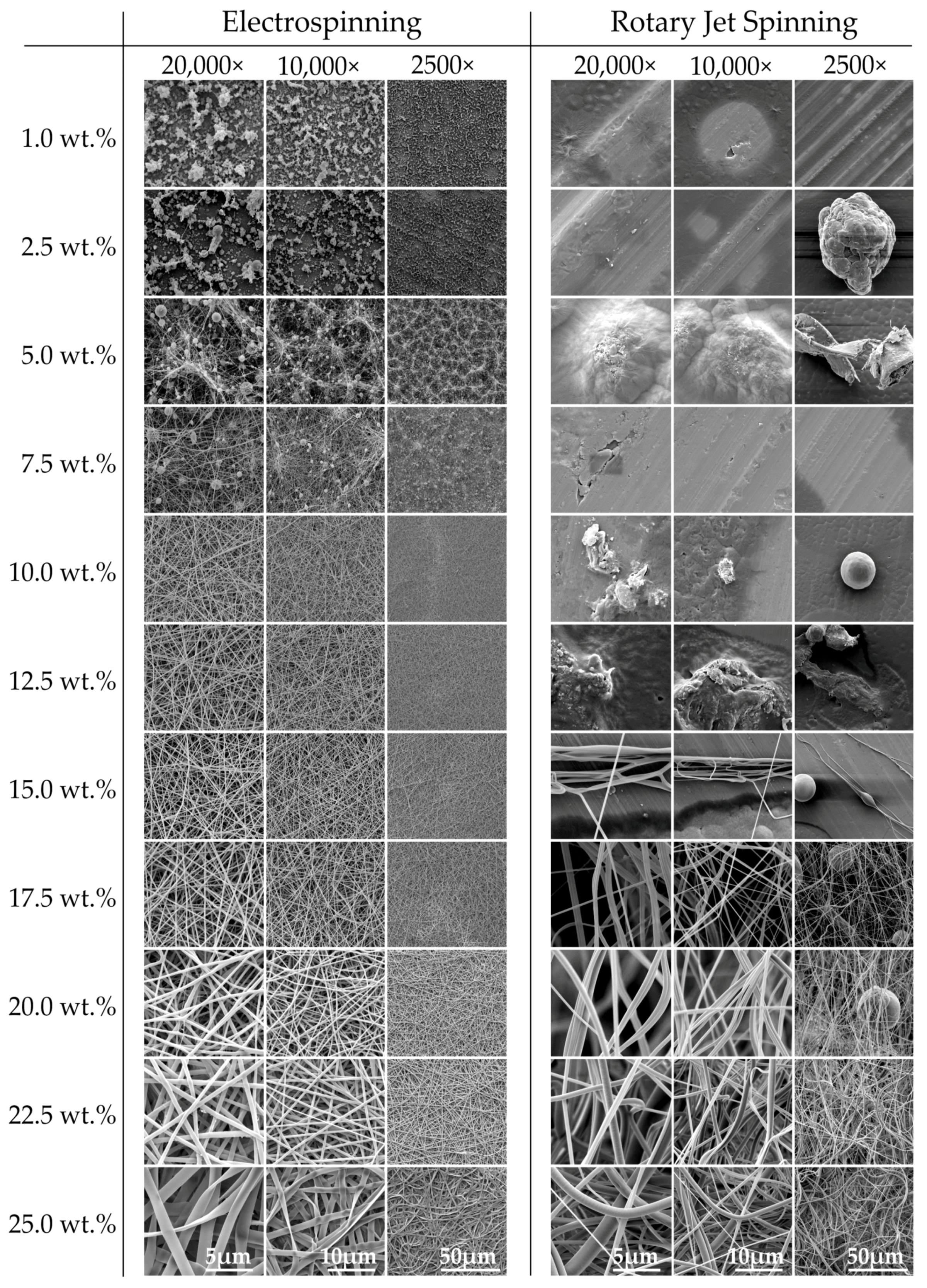
Figure 7.
Differential scanning calorimetry (DSC) heating traces of PA6 fibres from rotary jet spinning (RJS), electrospinning (ES) and the bulk polymer, showing identical melting peak temperatures for PA6 bulk and rotary jet spun fibres. The bulk polymer typically contains slower forming α-form crystal structures whereas faster forming γ-form crystals are present in the as-spun fibres due to the rapid evaporation of solvent from the spinning process.


Table 1.
Variation in processing parameters used in electrospinning and rotary jet spinning. The values highlighted in bold represent the best combination of parameters to produce fibres from the specified solution.
Table 1.
Variation in processing parameters used in electrospinning and rotary jet spinning. The values highlighted in bold represent the best combination of parameters to produce fibres from the specified solution.
| Electrospinning | Rotary Jet Spinning | |||
|---|---|---|---|---|
| PA6 Concentration (wt. %) | Viscosity (Pa·s) | Flow Rate (mL/h) | Applied Voltage (kV) | Angular Velocity (RPM × 1000) |
| 1.0 | 0.005 | 0.1, 0.15, 0.2 | 15, 20, 25 | 2, 4, 6, 8, 10 |
| 2.5 | 0.010 | 0.1, 0.15, 0.2 | 15, 20, 25 | 2, 4, 6, 8, 10 |
| 5.0 | 0.028 | 0.1, 0.15, 0.2 | 15, 20, 25 | 2, 4, 6, 8, 10 |
| 7.5 | 0.068 | 0.1, 0.15, 0.2 | 15, 20, 25 | 2, 4, 6, 8, 10 |
| 10.0 | 0.112 | 0.1, 0.15, 0.2 | 15, 20, 25 | 2, 4, 6, 8, 10 |
| 12.5 | 0.199 | 0.1, 0.15, 0.2 | 15, 20, 25 | 2, 4, 6, 8, 10 |
| 15.0 | 0.614 | 0.1, 0.15, 0.2 | 15, 20, 25 | 2, 4, 6, 8, 10 |
| 17.5 | 1.11 | 0.1, 0.15, 0.2 | 15, 20, 25 | 2, 4, 6, 8, 10 |
| 20.0 | 2.09 | 0.1, 0.15, 0.2 | 15, 20, 25 | 2, 4, 6, 8, 10 |
| 22.5 | 3.30 | 0.1, 0.15, 0.2 | 15, 20, 25 | 2, 4, 6, 8, 10 |
| 25.0 | 5.59 | 0.1, 0.15, 0.2 | 15, 20, 25 | 2, 4, 6, 8, 10 |
| 27.5 | 10.3 | 0.1, 0.15, 0.2 | 15, 20, 25 | 2, 4, 6, 8, 10 |
| 30.0 | 27.7 | 0.1, 0.15, 0.2 | 15, 20, 25 | 2, 4, 6, 8, 10 |
Table 2.
Range of fibre diameters from both electrospinning and rotary jet spinning, showing minimum, maximum, and range of the fibre diameters. Electrospinning produced a lower variance in measured fibre diameter compared with rotary jet spinning.
Table 2.
Range of fibre diameters from both electrospinning and rotary jet spinning, showing minimum, maximum, and range of the fibre diameters. Electrospinning produced a lower variance in measured fibre diameter compared with rotary jet spinning.
| Electrospinning—Fibre Diameter Range (µm) | ||||||||
| wt. % | 7.5 | 10 | 12.5 | 15 | 17.5 | 20 | 22.5 | 25 |
| dmin | 0.023 | 0.031 | 0.042 | 0.050 | 0.062 | 0.044 | 0.250 | 0.905 |
| dmax | 0.084 | 0.126 | 0.119 | 0.138 | 0.196 | 0.370 | 0.644 | 1.614 |
| drange | 0.061 | 0.095 | 0.077 | 0.088 | 0.134 | 0.325 | 0.395 | 0.709 |
| Rotary Jet Spinning—Fibre Diameter Range (µm) | ||||||||
| wt. % | 17.5 | 20 | 22.5 | 25 | ||||
| dmin | 0.156 | 0.300 | 0.250 | 0.175 | ||||
| dmax | 0.959 | 1.786 | 1.362 | 1.631 | ||||
| drange | 0.803 | 1.486 | 1.113 | 1.456 | ||||
Table 3.
Crystallinity comparison between electrospun fibres, rotary jet spun fibres, and bulk polymer, showing reduced crystallinity in PA6 fibre samples compared to bulk PA6 polymer.
Table 3.
Crystallinity comparison between electrospun fibres, rotary jet spun fibres, and bulk polymer, showing reduced crystallinity in PA6 fibre samples compared to bulk PA6 polymer.
| wt. % | Electrospun Fibre | Rotary Jet Spun Fibre | Bulk Polymer |
|---|---|---|---|
| 10.0 | 32% | No fibre | - |
| 12.5 | 35% | No fibre | - |
| 15.0 | 37% | No fibre | - |
| 17.5 | 35% | 30% | - |
| 20.0 | 29% | 32% | - |
| 22.5 | 33% | 28% | - |
| 25.0 | 31% | 29% | - |
| 100.0 | - | - | 44% |
| Average | 33% | 30% | 44% |
© 2018 by the authors. Licensee MDPI, Basel, Switzerland. This article is an open access article distributed under the terms and conditions of the Creative Commons Attribution (CC BY) license (http://creativecommons.org/licenses/by/4.0/).
Share and Cite
MDPI and ACS Style
Rogalski, J.J.; Bastiaansen, C.W.M.; Peijs, T. PA6 Nanofibre Production: A Comparison between Rotary Jet Spinning and Electrospinning. Fibers 2018, 6, 37. https://doi.org/10.3390/fib6020037
AMA Style
Rogalski JJ, Bastiaansen CWM, Peijs T. PA6 Nanofibre Production: A Comparison between Rotary Jet Spinning and Electrospinning. Fibers. 2018; 6(2):37. https://doi.org/10.3390/fib6020037
Chicago/Turabian StyleRogalski, James J., Cees W.M. Bastiaansen, and Ton Peijs. 2018. "PA6 Nanofibre Production: A Comparison between Rotary Jet Spinning and Electrospinning" Fibers 6, no. 2: 37. https://doi.org/10.3390/fib6020037
Note that from the first issue of 2016, this journal uses article numbers instead of page numbers. See further details here.