
Hollow-Core FRP–Concrete–Steel Bridge Columns under Torsional Loading
by
Sujith Anumolu
1, 
Omar I. Abdelkarim
2,
Mohanad M. Abdulazeez
3,
Ahmed Gheni
3 and
Mohamed A. ElGawady
3,* 1
Black & Veatch Corporation, Houston, TX 77027, USA
2
Department of Civil Engineering, University of Sherbrooke, Sherbrooke, QC J1K 2R1, Canada
3
Department of Civil, Architectural, and Environmental Engineering, Missouri University of Science and Technology, Rolla, MO 65409, USA
*
Author to whom correspondence should be addressed.
Fibers 2017, 5(4), 44; https://doi.org/10.3390/fib5040044
Submission received: 16 August 2017
/
Revised: 13 October 2017
/
Accepted: 16 October 2017
/
Published: 14 November 2017
(This article belongs to the Special Issue Fiber Reinforced Polymer Composites or Polymer-Carbon Nanotube Nanocomposites)
Abstract
:This paper presents the behavior of hollow-core fiber-reinforced polymer–concrete–steel (HC-FCS) columns under cyclic torsional loading combined with constant axial load. The HC-FCS consists of an outer fiber-reinforced polymer (FRP) tube and an inner steel tube, with a concrete shell sandwiched between the two tubes. The FRP tube was stopped at the surface of the footing, and provided confinement to the concrete shell from the outer direction. The steel tube was embedded into the footing to a length of 1.8 times the diameter of the steel tube. The longitudinal and transversal reinforcements of the column were provided by the steel tube only. A large-scale HC-FCS column with a diameter of 24 in. (610 mm) and applied load height of 96 in. (2438 mm) with an aspect ratio of four was investigated during this study. The study revealed that the torsional behavior of the HC-FCS column mainly depended on the stiffness of the steel tube and the interactions among the column components (concrete shell, steel tube, and FRP tube). A brief comparison of torsional behavior was made between the conventional reinforced concrete columns and the HC-FCS column. The comparison illustrated that both column types showed high initial stiffness under torsional loading. However, the HC-FCS column maintained the torsion strength until a high twist angle, while the conventional reinforced concrete column did not.
1. Introduction
Bridge columns sustain axial, flexural, shear, and torsional loads during earthquakes. Researchers attempt to develop new structural systems that can increase the resilience and accelerate the construction of bridge columns [1,2]. Concrete-filled steel tubes (CFST) are one of those developed systems. The external steel tube acts as a stay-in-place formwork that provides longitudinal and transverse reinforcement, and a confinement reinforcement to the concrete core. The concrete core acts as a bracing that provides lateral stability and delays the local buckling of the steel tube. The combination of steel tube and concrete enhances the overall strength and ductility of the column. The material cost of the CFST column is slightly higher than that of the conventional reinforced concrete columns, while it is lower than the steel columns. CFSTs are used as bridge columns in Europe, China, and Japan, and extend to the United States as piles. Recently, fiber-reinforced polymer (FRP) tubes have been used instead of steel tubes due to their high strength-to-weight ratios and corrosion resistance [3,4,5,6,7,8,9,10,11].
Montague [12] introduced a new system, hollow-core steel-concrete-steel columns, by hollowing a concrete-filled steel tube column and supported the remaining concrete shell by an inner steel tube. The self-weight of the column is significantly decreased, which leads to reduced inertial forces linked to the column’s weight. Teng et al. [13] replaced the outer steel tube of the hollow-core steel–concrete–steel column with an outer FRP tube, producing hollow-core FRP–concrete–steel (HC-FCS) columns. The HC-FCS column exploits the benefits of the three materials, i.e., FRP, concrete, and steel. The FRP tube and concrete core reduce the potentials of the corrosion of the inner steel tube. The concrete shell also reduces the outward local buckling of the steel tube, leading to higher models buckling at higher loads. Several researchers have investigated the performance of HC-FCS columns under different loading conditions [14,15,16,17,18,19,20]. These studies showed that HC-FCS columns could exhibit high levels of lateral drift and energy dissipation before the rupture of the FRP tube.
Bridge columns in skewed, curved, and asymmetric structures may sustain significant torsional loads during earthquakes. Earthquakes typically induce cyclic torsional loads combined with axial and/or flexural loadings, which increase the demand on a bridge column. Ostuska et al. [21] and Prakash [22] reported that the locking and unlocking of the spiral reinforcement had significantly affected the column’s cyclic torsional behavior. Moreover, the spalling of concrete was higher during the unlocking of the spiral compared with the locking of the spiral.
Beck and Kiyomiya [23] reported that buckling of the steel tube of the CFST column subjected to pure torsional monotonic loads was delayed due to the existence of the concrete core, and the column maintained its high stiffness and displayed high ductility compared with equivalent reinforced concrete columns. Han et al. [24] reported that the concrete core had a significant effect on the torsional resistance of CFST columns subjected to pure monotonic torsional loads. They also developed an analytical model to calculate the column’s torque. Nie et al. [25] investigated the behavior of CFSTs under pure torsional and combined axial-torsional cyclic loading. They revealed that the CFSTs had high-energy dissipation and insignificant strength degradation.
Recently, Huang et al. [26] and Anumolu et al. [27] investigated the behavior of hollow-core steel–concrete–steel columns under pure torsion, and reported a good energy dissipation of such columns along with high strength and ductility. Anumolu et al. [27] proposed design formulas for calculating the ultimate torque of hollow-core steel–concrete–steel columns.
2. Research Significance
There have not been any studies that investigate the behavior of the HC-FCS columns under torsional loading. This manuscript presents a unique study that investigates the behavior of a HC-FCS column subjected to combine cyclic torsional and axial compressive loading. A large-scale HC-FCS column was constructed and experimentally examined under the designed loads. The general torsional behavior of the HC-FCS column was compared with that of a reinforced concrete column.
3. Experimental Program
3.1. Test Specimen
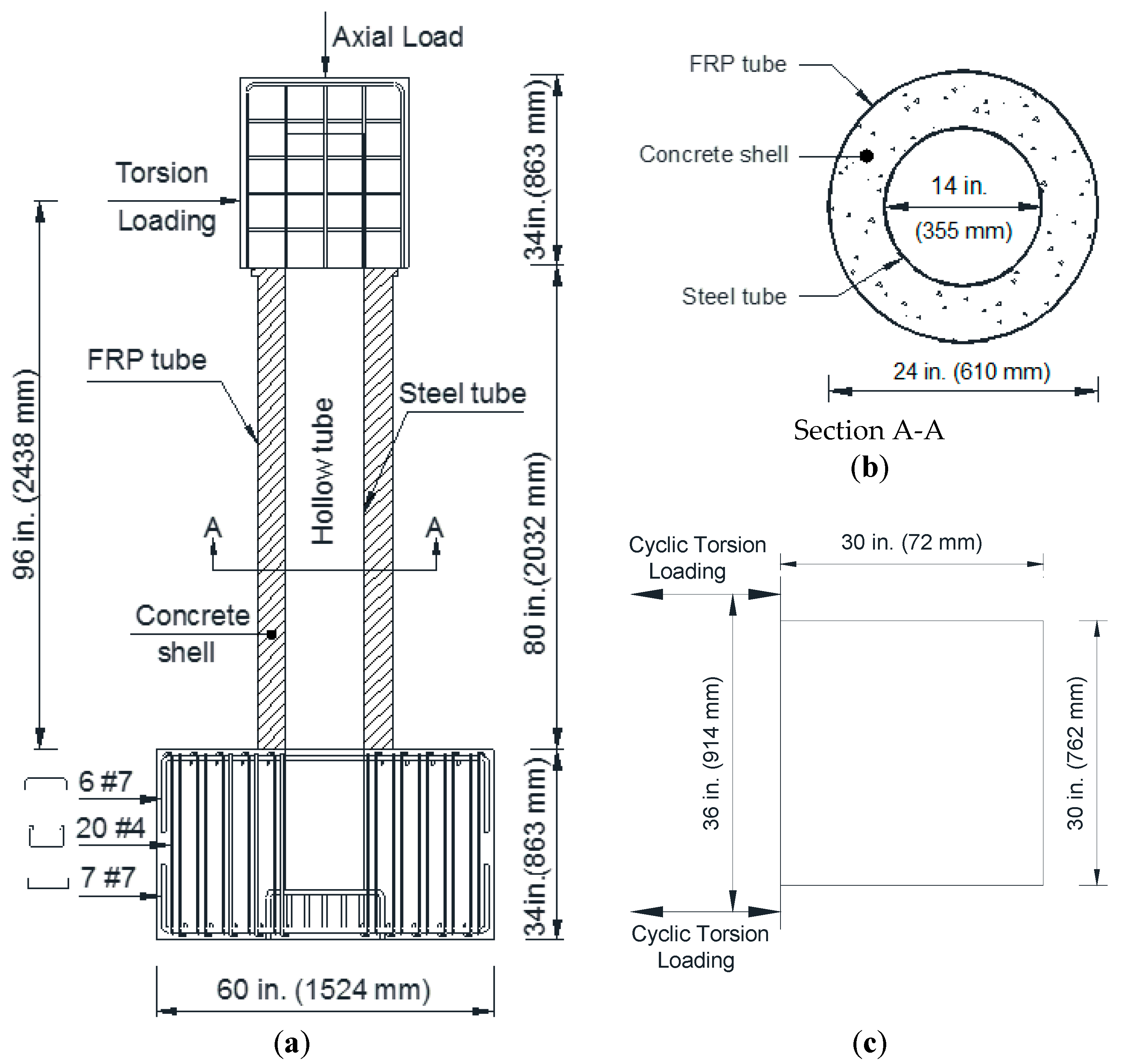
A large-scale HC-FCS column was constructed (Figure 1) and tested under cyclic torsional loading and constant axial compressive load. The column’s actual height between the surfaces of the footing and the loading head was 80 in. (2032 mm). The column’s shear span from the top surface of the footing to the center-line of the applied torsional load was 96 in. (2438 mm), representing a moment span-to-shear diameter ratio of four. The diameter of the outer glass fiber-reinforced polymer (GFRP) tube (Do) and the inner steel tube (Di) were 24 in. (610 mm) and 14 in. (355 mm), respectively. The concrete shell thickness was 5 in. (127 mm). The thickness of the GFRP tube (to) was 0.45 in. (11 mm). The thickness of the steel tube (ti) was 0.25 in. (6.35 mm), representing a diameter-to-thickness (Di/ti) ratio of 56. The percentage area of the steel tube over the gross cross-sectional area of the column was 2.15%, which was approximately equal to the same amount of the longitudinal and transversal reinforcements in a conventional reinforced concrete column in the Midwestern United States.
The steel tube of the column was embedded into the footing and loading stub, while the GFRP tube was not embedded in either one. Therefore, the GFRP tube acted as a stay-in-place formwork and confinement reinforcement for the column, while it did not transfer any flexural loads to the footing or the loading stub. While embedding the GFRP tube may increase the strength of a HC-FCS column, it may also lead to a very brittle failure due to the rupture of the GFRP. Furthermore, truncating the GFRP at the surface of the footing allowed the use of a precast HC-FCS column with a simple socket connection (Abdelkarim et al. 2016). The embedded length of the steel tube into the footing and loading stub was 25 in. (635 mm), representing 1.8 times the diameter of the steel tube.
The dimensions of the footing were 60 in. (1524 mm) in length, 48 in. (1219 mm) in width, and 34 in. (863 mm) in depth. The footing was constructed using 6#7 (6 D22) as top reinforcement, 7#7 (7 D22) as bottom reinforcement, and 20#4 (20 D13) as shear reinforcement (Figure 1). The dimensions of the loading stub were 30 in. (762 mm) in length, 30 in. (762 mm) in width, and 34 in. (863 mm) in depth. A clear cover of 1 in. (25.4 mm) was used in all of the sides of the footing and the loading stub. The construction joint at the top of footing level was well prepared before pouring the concrete column by roughing the surface using a needle gun. The top surface of the concrete column was prepared in the same way before pouring the loading stub.
3.2. Material Properties
The GFRP tube was manufactured by filament winding of glass fibers and epoxy resin. The fiber orientation was ±55° to the axial direction of the tube. The GFRP longitudinal tensile strength was determined per the ASTM D3039 [28] as 9500 psi (65.5 MPa), which was very close to the manufacturer’s data (Table 1). The hoop strength per the manufacturer’s data is summarized in Table 1.
Tension tests per the ASTM A1067 [29] were conducted on steel coupons obtained from the longitudinal direction of the steel tube (Table 2). The tests were carried out on a universal testing machine with a 0.05 in./min (1.27 mm/min) constant loading rate.
The mix proportions of the concrete shell are summarized in Table 3. The coarse aggregate used for the concrete shell was pea gravel, with a maximum aggregate size of 3/8 in. (9 mm). The water–cement (w/c) ratio was maintained at 0.5. The workability of the concrete shell was increased using high range water reducers. The concrete cylinders of the concrete shell and the footing were tested at 28 days and the day of testing. The concrete mixture had a 28-day compressive strength of 5158 psi (35.5 MPa). The column was tested at four months after the construction, and the concrete strength reached 6910 psi (51 MPa). The increase in the strength was due to the slow hydration of the fly ash. The compressive strength of the concrete of the footing was 9700 psi (66.9 MPa) at the day of testing (Table 4).
3.3. Experimental Setup and Instrumentation
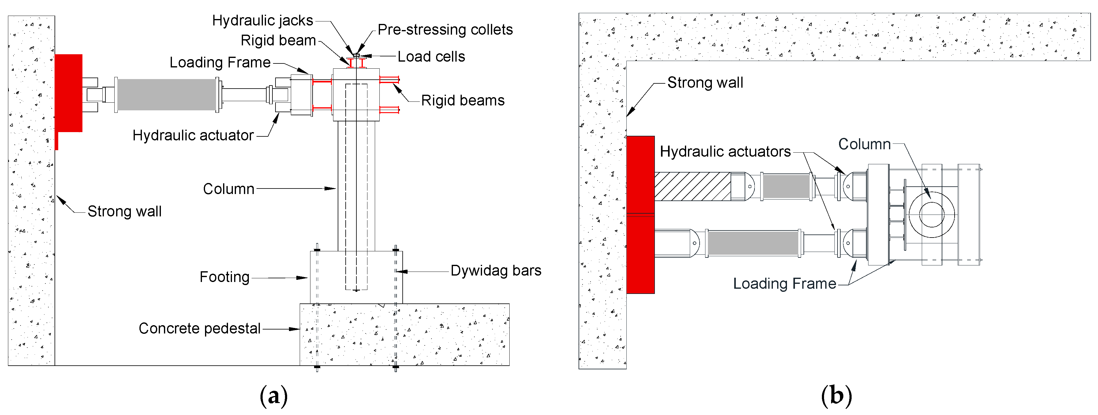
The schematic test setup is shown in Figure 2. The footing was fixed to the strong floor using four Dywidag bars. Two servo-controlled hydraulic horizontal actuators were used at the northern side to apply cyclic torsional load. The actuators were connected at one end to the loading stub using post-tensioned Dywidag bars and steel beams (Figure 2). The other end of each actuator was connected to the laboratory strong wall. The axial load was applied to the column loading stub using six external unbonded prestressed tendons. The tendons had dead ends at the footing and active ends at the loading stub. The axial load remained constant during testing using a controlled servo-valve.
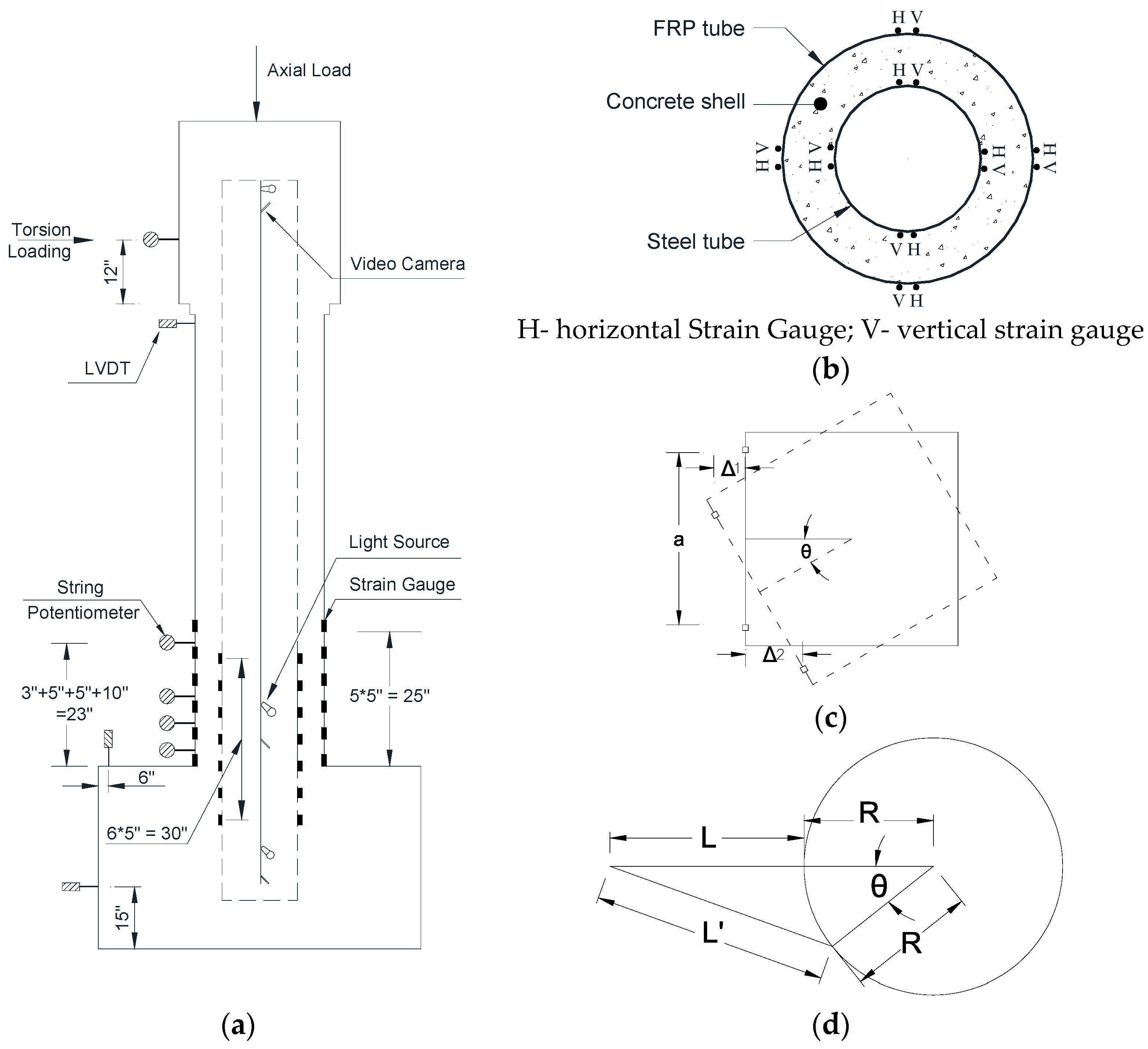
Strain gauges, strain rosettes, linear variable differential transformer (LVDTs) and string potentiometers were used to measure the deflection, deformations, and strains of the investigated column. A total of 48 strain gauges were attached to the FRP tube at six levels with pitches of 5 in. (127 mm) starting from the surface level of the footing to 25 in. (635 mm) along the height of the column. At each level, a total of eight strain gauges, with four on the hoop direction and four on the vertical direction, were attached on the east, west, north, and south directions. A total of 56 strain gauges were attached on the steel tube at seven levels, with spacing of 5 in. (127 mm) from 15 in. (381 mm) to 45 in. (635 mm) from the bottom of the steel tube along the height of the column. At each level, a total of eight strain gauges, with four on the hoop direction and four on the vertical direction, were attached on the east, west, north, and south directions. Two strain rosettes were attached on the steel tube at the surface level of the footing, and 5 in. (127 mm) above it on the north direction. Each strain rosette measured shear strain along with longitudinal strain and hoop strain. The buckling behavior and slip of the steel tube and of the steel tube over concrete were monitored using cameras fixed inside the steel tube. A total of three cameras were fixed inside the steel tube, along with light bulbs to provide illumination. The cameras were positioned to focus on the steel tube at three levels: top, bottom, and at the surface level of the footing. String potentiometers were used to measure the twist angle of the column. A total of six string potentiometers were attached at different locations over the column height. LVDTs were used to measure the rocking and sliding of the footing, if any, and the slip of the FRP tube over the loading head. The detailed instrumentation of the column was shown in Figure 3.
3.4. Measuring of the Column Twist Angle
The column’s twist angle is the angle of rotation of the column’s head around its center. From Figure 3c, the distance between the two actuators on the loading head “a” was 914 mm. The column rotated to a twist angle of θ, and the respective displacements Δ1 and Δ2 were determined from the actuators readings. Hence, the column’s twist angle was determined using Equation (1). Also, the rotation of the FRP tube was monitored in order to measure any slip occurring between the FRP tube and the column’s head during the application of the torsional loading. A string of length L from the string potentiometer was attached to the top of the FRP tube of the column (Figure 3a,d). The twist angle of the FRP “θ1” was determined using Equations (2) and (3). The relative twist angle between the column’s head and the FRP tube was determined by subtracting “θ1” from “θ”. Another method was used to measure the relative displacement between the FRP tube and the column’s head, where a wooden plate was attached to the top of the FRP tube parallel to the loading frame, and two LVDTs were attached horizontally to the loading frame and connected to the wooden plate to measure the respective displacements. Hence, the relative displacement was determined as similar to Equation (1). Finally, the two methods determining the relative displacements between the column’s head and the FRP tube had very close results.
3.5. Loading Protocol
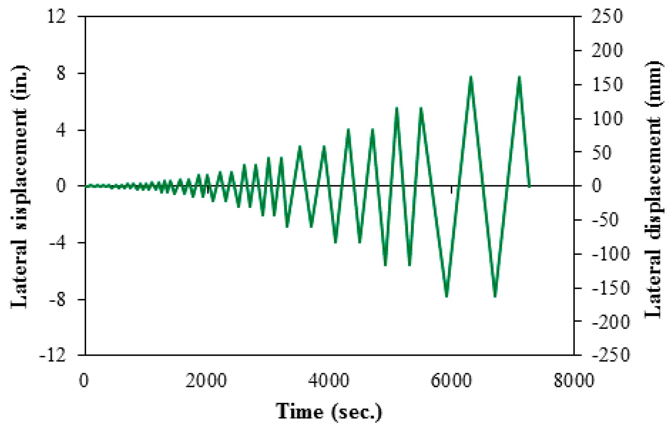
The axial load of 55 kips (245 kN) was applied on each hydraulic jack, with a total axial force of 110 kips (490 kN), which represents 5% axial capacity of a reinforced concrete column with the same outer diameter, and 1% longitudinal reinforcement [30]. The axial load was maintained constant throughout the test and was monitored using load cells. The torsional load was applied through two servo-controlled hydraulic horizontal actuators from the north direction. A displacement control technique was adopted to apply the torsional load to the column. The displacements of the two actuators were maintained at equal in value and opposite in direction. The loading regime of the actuators was based on the FEMA 461 [31] recommendations, in which the displacement amplitude of each actuator was 1.4 times the previous displacement amplitude. Each of the displacement amplitudes comprised two cycles. The displacement rate of each actuator was varied between 0.01 in./s (0.25 mm/s) and 0.04 in./s (1.00 mm/s). The loading regime used for cyclic torsional loading was shown in Figure 4.
4. Results and Discussion
4.1. General Behavior
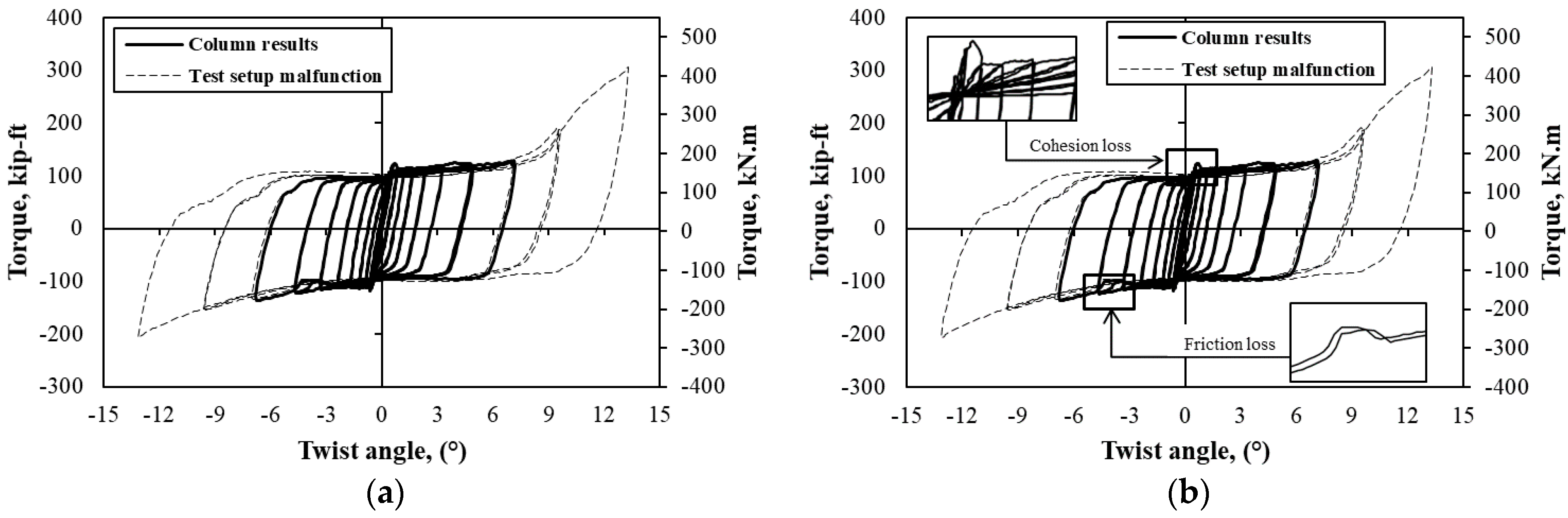
The torque—twist angle hysteretic curve of the HC-FCS column is shown in Figure 5. The torque of the column was calculated by the summation of forces obtained from each actuator through the load cells multiplied by half the distance between the actuators, which was 18 in. (457 mm). The actual twist angle of the column was obtained by subtracting the sliding effect of the footing during the test, which was minimal, from the twist angle of the column. From Figure 5, the column behaved linearly until a twist angle of 0.5°. By this twist angle, the column gained early stiffness, and reached 70% of the column’s ultimate torque. After this twist angle, the relation between the twist angle and the torque was almost horizontal, with a low torsional stiffness. The relation started to have an abnormal deviation at a twist angle of 7° due to the additional force provided from the actuator, because of the rotational constraint of the actuator arm. The experiment was stopped at a twist angle of 13.3° because of the actuator limitation. However, the torque capacity of the column was considered at a twist angle of 7°. The torque after this twist angle was considered as a test setup malfunction because of the effect of the actuator, as shown in Figure 5. The column reached a torque capacity of 128 kip-ft (173.5 kN.m) in the positive cycle and 135 kip-ft (185 kN-m) in the negative cycle at a twist angle of 7°.
The cohesion loss (Figure 5b) occurred between the loading head and the concrete shell at a 0.5° twist angle, and resulted in slight degradation in the torque-twist angle curve; however, the drop was very low. After the loss of cohesion, the torque of the column was mainly dependent on the stiffness of the steel tube and frictional force exerted between the concrete elements (footing, concrete shell, and loading head) and steel tube. That was the reason that the torque of the column continued to increase at low torsional stiffness. Unlike under the flexural loading [15], the contribution of the GFRP tube towards torsional resistance was negligible, since there was no firm fixation of the FRP tube in the axial direction. The rigidity of the GFRP tube allowed the rotation of the GFRP tube along with the concrete shell.
The drop in the curve (Figure 5b) at a twist angle of 3.5° in the negative cycles was due to the sudden sliding of the steel tube over the concrete. The sudden sliding was noticed by the strain gauge readings and the cameras fixed inside the steel tube at this twist angle. However, at higher rotations, the concrete dilation increased with its cracks and damage, which applied a higher lateral pressure on the steel tube providing higher friction. This behavior prevented the sliding of the steel tube at the higher displacement cycles. However, the torque continued to increase due to gains in the frictional force between the steel tube and the concrete. At higher load levels, the column’s torque mainly depended on the friction exerted between the concrete and the steel tube.
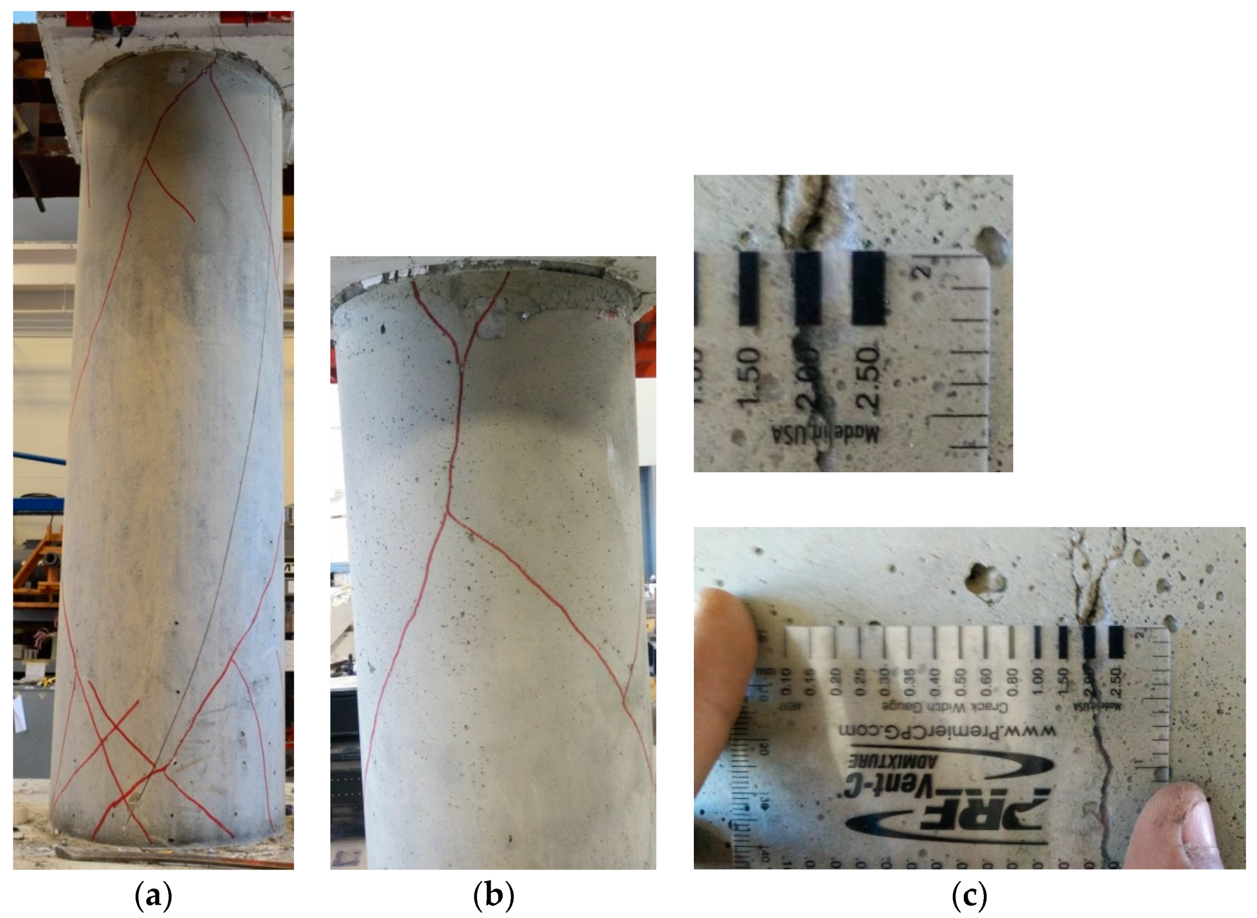
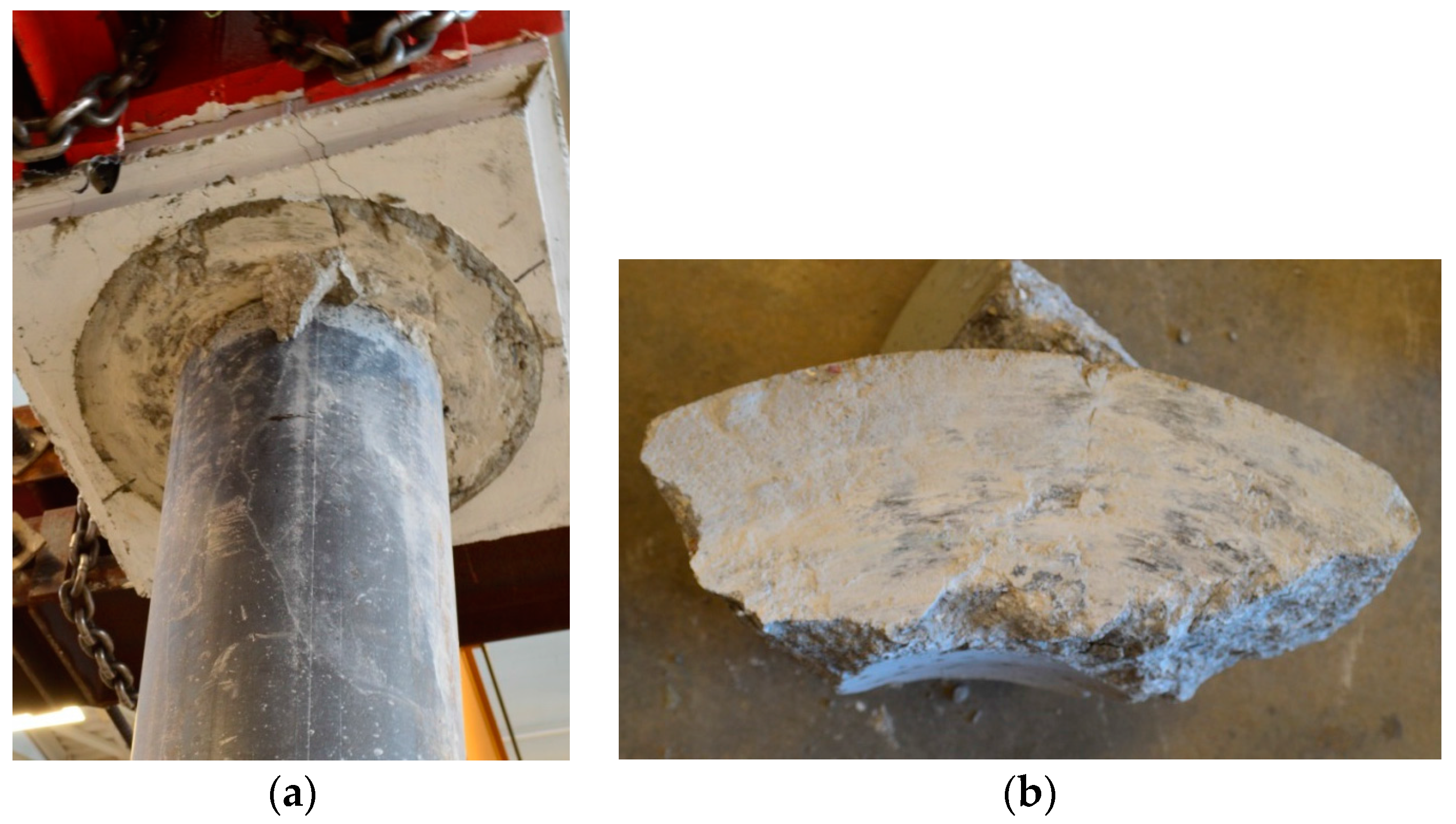
After the test, the GFRP tube had no visual damage, and was removed to observe the state of the concrete shell. Several cracks were discovered throughout the height of the column at an angle of approximately 45° (Figure 6). The maximum crack width on the concrete shell was 0.8 in. (2 mm), which occurred at the top region of the column. A significant number of cracks were observed at the bottom of the column compared with the top of the column. The reason was that the frictional force exerted between the footing and concrete shell was higher than that between the concrete shell and loading head because of the column self-weight. The high friction between the footing and the concrete shell constrained the rotation of the concrete shell over the footing, whereas the low friction between the concrete shell and loading head allowed the rotation of the loading head over the concrete shell. The contact surfaces of the loading head and the concrete shell became smooth at the end of the test. The loading action in both directions ground the concrete surfaces and made them smooth (Figure 7). The contact surfaces of the footing and the concrete column were still rough, which confirmed the higher friction exerted in the contact. The steel tube was intact with the footing and head concrete surfaces. No visual deformations were observed in the steel tube.
4.2. Relative Sliding of GFRP Tube and Steel Tube
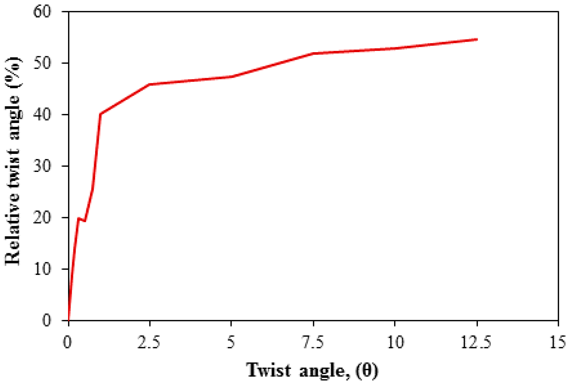
The column’s profile at a twist angle of 9° is shown in Figure 8a. The relative sliding between the steel tube and the concrete shell, and between the concrete shell and the loading head caused a relative twist angle between the GFRP tube with the concrete shell and the loading head (Figure 8b and Figure 9). The relative twist angle was calculated at the point of loading, and the top of the GFRP tube. The relative twist angle, per Equation (4), was a ratio of the difference in the twist angle of the column and the rotation of GFRP tube to the twist angle of the column. The relative twist angle between the GFRP tube with the concrete shell and loading head had been noticed from the small twist angles of the column. Due to the lack of rigid fixation of the FRP tube at the both ends, the rotation along the GFRP tube’s height remained constant (Figure 9). The twist angle of the GFRP tube was almost half the twist angle of the column at high degrees of rotation.
For the column’s smaller twist angles (i.e., 0.1° to 0.3°), the relative twist angle was below 20%, as shown in Figure 10. The drop in the curve at the twist angle of 0.5° in Figure 10 confirmed the cohesion loss between the concrete shell and loading head, since the GFRP tube and concrete shell were intact with each other during the test (Figure 5b). The relative twist angle reached 40% at a twist angle of 1°, and continued increasing to 55% at a 12.5° twist angle.
4.3. Strain Profile
The vertical and hoop strain profiles along the height of the GFRP and steel tubes are shown in Figure 11. In general, the GFRP tube experienced vertical compressive strains along the height where considerable strains were within the bottommost 10 in. (254 mm), with a maximum vertical compressive strain of 950μ (Figure 11a). Although the GFRP hoop strains were all in tension along the height, the values were very small, which indicated that the GFRP confinement was negligible (Figure 11b). The GFRP hoop and vertical strains decreased with movement away from the surface of the footing along the height. It was worth noting that the GFRP vertical and hoop strain profiles at twist angles of 10° and 13.3° had very similar values. This indicated that the GFRP tube with the concrete shell almost separated from the rotation of the steel tube, as the GFRP tube did not gain any more strains with the twisting of the column. This result agreed with the relative twist angle results. The steel tube yielded vertically only at the twist angle of 13.3°, while it did not yield in the hoop direction (Figure 11c,d). The vertical steel strain at 20 in. (508 mm) from the surface of the footing was almost zero. The steel tube hoop strains at the surface level of the footing were not consistent with the overall strains’ profiles. The reason was due to the abrupt change in the stability condition at the footing top level, where the concrete shell cracked and had friction forces with the footing top surface unlike the other levels. At a 13.3° twist angle, the steel hoop strain reached approximately 50% of the yield strain at the surface level of the footing (Figure 11d). The higher steel hoop strains at the surface of the footing indicated the friction forces exerted at this level. The shear strain from the strain rosettes on the steel tube at heights of 5 in. (127 mm) and 10 in. (254 mm) from the surface of the footing are shown in Figure 12. The shear strain on the steel tube at the surface level of the footing was 800μ, which was far below the shear yield strain of the steel tube, which was 2800μ. It is worth noting that the strain redistribution was not noticed in the steel tube, unlike in the case of axial loading when the GFRP was used [32,33,34,35]. The reason was that the column relied mainly on the steel tube resistance under torsion loading, and the effect of the GFRP tube was negligible.
4.4. Comparison of Torsional Behavior with RC Column from Previous Studies
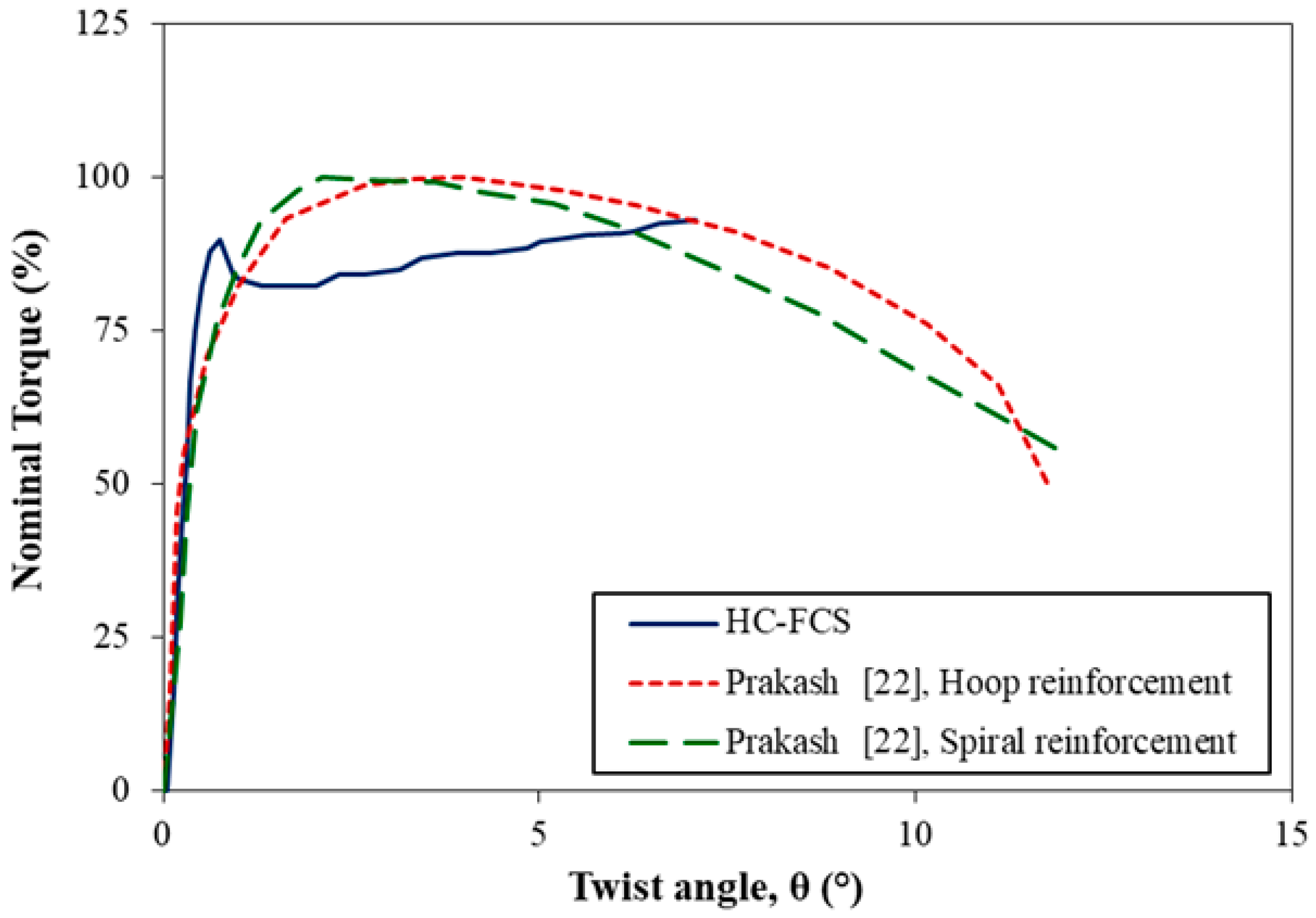
A comparison of the torsional behavior was conducted between the investigation of the HC-FCS column and two reinforced concrete (RC) columns that have been presented in detail in Prakash’s Ph.D. thesis [22]. Prakash [22] tested two RC columns with a diameter of 24 in. (610 mm) that represented a height-to-diameter ratio of six. The transverse reinforcement was hoop for one column, and spiral for the other, with a reinforcement volumetric ratio of 0.73%, with 2.75 in. (70 mm) spacing for both of the columns. Figure 13 illustrates the twist angle percentage vs. the torque percentage for the HC-FCS column and two RC columns. The torque values were normalized by the ultimate torque value. As shown in Figure 13, the three columns displayed similar early torsional stiffness. The reinforced concrete columns with spiral or hoop reinforcement started to lose their torsional strengths at a twist angle of 3°, whereas the HC-FCS column maintained its strength until a twist angle of 7°. The RC columns lost approximately 15% of their ultimate torque at a twist angle of 7°, whereas the HC-FCS column kept its ultimate torque (Figure 13).
5. Summary and Conclusions
The torsional behavior of a large-scale hollow-core FRP–concrete–steel (HC-FCS) column was investigated. The HC-FCS column had a 24 in. (610 mm) outer diameter with a shear span-to-diameter ratio of 4.0. The HC-FCS column consisted of a concrete shell sandwiched between an outer GFRP tube and an inner steel tube. No steel bars were provided in the HC-FCS column. The GFRP tube was placed on the surface of the footing, and the steel tube was embedded into the footing using a length of 1.8 times the steel tube’s diameter. This study is based on one large-scale column to show the qualifications of the HC-FCS column under torsional loading. However, further investigations on the different parameters should be conducted in future research to show the effect of each parameter. The following conclusions were revealed:
- The torsional behavior of the HC-FCS column depended on the steel tube’s stiffness and the friction existing between the column’s components.
- The stiffness of the HC-FCS column was maintained even at large twists, and exhibited good ductility.
- The direct contribution of the GFRP tube towards the torque was negligible.
- The HC-FCS column was able to sustain its torque strength along twist angles significantly higher than those of the comparable reinforced concrete columns. The reinforced concrete columns displayed a significant reduction in its torque capacities starting at twist angle of 3°, whereas the HC-FCS column maintained its strength until a twist angle of 7°.
Acknowledgments
This research was conducted by the Missouri University of Science and Technology. In kind contribution from ATLAS Tube is appreciated. Discounts on FRP tubes from Grace Composites and FRP Bridge Drain Pipe are also appreciated. The authors also extend their appreciation to the National University Transportation Center (NUTC) at Missouri University of Science and Technology (Missouri S&T). However, any opinions, findings, conclusions, and recommendations presented in this paper are those of the authors and do not necessarily reflect the views of the sponsors.
Author Contributions
The research idea belongs to ElGawady. Sujith Anumolu and Omar I. Abdelkarim designed and conducted the experimental work and prepared the paper following Mohamed A. ElGawady’s instructions and under his supervision. Mohanad M. Abdulazeez and Ahmed Gheni significantly contributed to the experimental work.
Conflicts of Interest
The authors declare no conflict of interest.
References
- Dawood, H.; ElGawady, M.A.; Hewes, J. Factors affecting the seismic behavior of segmental precast bridge columns. Front. Struct. Civ. Eng. J. 2014, 8, 388–398. [Google Scholar] [CrossRef]
- Abdelkarim, O.I.; ElGawady, M.A. Analytical and finite-element modeling of FRP-concrete-steel double-skin tubular columns. J. Bridge Eng. 2014, 20, B4014005. [Google Scholar] [CrossRef]
- Mirmiran, A.; Shahawy, M. A new concrete-filled hollow FRP composite column. Compos. Part B Eng. 1996, 27, 263–268. [Google Scholar] [CrossRef]
- Youssf, O.; ElGawady, M.A.; Mills, J. Finite element modelling and dilation of FRP-confined concrete columns. Eng. Struct. 2014, 79, 70–85. [Google Scholar] [CrossRef]
- Youssf, O.; ElGawady, M.A.; Mills, J. Static cyclic behaviour of FRP-confined crumb rubber concrete columns. Eng. Struct. 2016, 113, 371–387. [Google Scholar] [CrossRef]
- Abdelkarim, O.I.; ElGawady, M.A. Dynamic and static behavior of hollow-core FRP-concrete-steel and reinforced concrete bridge columns under vehicle collision. Polymers 2016, 8, 432. [Google Scholar] [CrossRef]
- Abdelkarim, O.I.; ElGawady, M.A. Behavior of hollow FRP-concrete-steel columns under static cyclic axial compressive loading. Eng. Struct. 2016, 123, 77–88. [Google Scholar] [CrossRef]
- Ozbakkaloglu, T. Axial compressive behavior of square and rectangular high-strength concrete-filled FRP Tubes. J. Compos. Constr. 2012, 17, 151–161. [Google Scholar] [CrossRef]
- Mirmiran, A.; Mohsen, S.; Thomas, B. Slenderness limit for hybrid FRP-concrete columns. J. Compos. Constr. 2001, 5, 26–34. [Google Scholar] [CrossRef]
- Lam, L.; Teng, J.G. Ultimate condition of fiber reinforced polymer-confined concrete. J. Compos. Constr. 2004, 8, 539–548. [Google Scholar] [CrossRef]
- Abdelkarim, O.I.; ElGawady, M.A. Concrete-filled-large deformable FRP tubular columns under axial compressive loading. Fibers 2015, 3, 432–449. [Google Scholar] [CrossRef]
- Montague, P. Experimental behavior of double-skinned, composite, circular cylindrical-shells under external-pressure. J. Mech. Eng. Sci. 1978, 20, 21–34. [Google Scholar] [CrossRef]
- Teng, J.G.; Yu, T.; Wong, Y.L. Behavior of hybrid FRP-concrete-steel double-skin tubular columns. In Proceedings of the 2nd International Conference on FRP Composites in Civil Engineering, Adelaide, Australia, 8–10 December 2004; pp. 811–818. [Google Scholar]
- Teng, J.G.; Yu, T.; Wong, Y.L.; Dong, S.L. Hybrid FRP concrete-steel tubular columns: Concept and behavior. Constr. Build. Mater. 2007, 21, 846–854. [Google Scholar] [CrossRef]
- Abdelkarim, O.I.; ElGawady, M.A.; Gheni, A.; Anumolu, S.; Abdulazeez, M. Seismic performance of innovative hollow-core FRP–concrete–steel bridge columns. J. Bridge Eng. 2016, 22, 04016120. [Google Scholar] [CrossRef]
- Yu, T.; Wong, Y.; Teng, J.; Dong, S.; Lam, E. Flexural behavior of hybrid FRP-concrete-steel double-skin tubular members. J. Compos. Constr. 2006, 10, 443–452. [Google Scholar] [CrossRef]
- Wong, Y.L.; Yu, T.; Teng, J.G.; Dong, S.L. Behavior of FRP-confined concrete in annular section columns. Compos. Part B Eng. 2008, 39, 451–466. [Google Scholar] [CrossRef]
- Ozbakkaloglu, T.; Akin, E. Behavior of FRP-confined normal-and high-strength concrete under cyclic axial compression. J. Compos. Constr. 2011, 16, 451–463. [Google Scholar] [CrossRef]
- Zhang, B.; Teng, J.G.; Yu, T. Experimental behavior of hybrid FRP–concrete–steel double-skin tubular columns under combined axial compression and cyclic lateral loading. Eng. Struct. 2015, 99, 214–231. [Google Scholar] [CrossRef]
- Moustafa, A.; ElGawady, M.A. Strain rate effect on properties of rubberized concrete confined with glass fiber–reinforced polymers. J. Compos. Constr. 2016, 20, 04016014:1–04016014:13. [Google Scholar] [CrossRef]
- Otuska, H.; Takeshita, E.; Yabuki, W.; Wang, Y.; Yoshimura, T.; Tsunomoto, M. Study on the seismic performance of reinforced concrete columns subjected to torsional moment, bending moment and axial force. In Proceedings of the 13th World Conference on Earthquake Engineering, Vancouver, BC, Canada, 1–6 August 2004. [Google Scholar]
- Prakash, S.S. Seismic behavior of circular reinforced concrete bridge columns under combined loading including torsion. Ph.D. Thesis, Missouri University of Science and Technology, Rolla, MO, USA, 2009. [Google Scholar]
- Beck, J.; Kiyomiya, O. Fundamental pure torsion properties of concrete filled circular steel tubes. J. Mater. Conc. Struct. Pavements 2003, 60, 85–96. [Google Scholar]
- Han, L.H.; Yao, G.H.; Tao, Z. Performance of concrete-filled thin-walled steel tubes subjected to pure torsion. Thin-Walled Struct. 2007, 45, 24–36. [Google Scholar] [CrossRef]
- Nie, J.G.; Wang, Y.H.; Fan, J.S. Experimental study on seismic behavior of concrete filled steel tube columns under pure torsion and compression–torsion cyclic load. J. Constr. Steel Res. 2012, 79, 115–126. [Google Scholar] [CrossRef]
- Huang, H.; Han, L.H.; Zhao, X. Investigation on concrete filled double skin steel tubes (CFDSTs) under pure torsion. J. Constr. Steel Res. 2013, 90, 221–234. [Google Scholar] [CrossRef]
- Anumolu, S.; Abdelkarim, O.I.; ElGawady, M.A. Behavior of hollow-core steel-concrete-steel columns subjected to torsion loading. J. Bridge Eng. 2016, 21, 04016070. [Google Scholar] [CrossRef]
- ASTM. Standard Test Method for Tensile Properties of Polymer Matrix Composite Materials; Standard D3039/D3039M; ASTM: West Conshohocken, PA, USA, 2014. [Google Scholar]
- ASTM. Standard Specification for Test Coupons for Steel Castings; Standard A1067; ASTM: West Conshohocken, PA, USA, 2012. [Google Scholar]
- Abdelkarim, O.; Gheni, A.; Anumolu, S.; ElGawady, M. Seismic behavior of hollow-core FRP-concrete-steel bridge columns. ASCE Struct. Congr. 2015, N/A, 585–596. [Google Scholar]
- FEMA. Interim Testing Protocols for Determining the Seismic Performance Characteristics of Structural and Nonstructural Components; FEMA 461; FEMA: Washington, DC, USA, 2007. [Google Scholar]
- Rousakis, T.C. Reusable and recyclable nonbonded composite tapes and ropes for concrete columns confinement. Compos. Part B Eng. 2016, 103, 15–22. [Google Scholar] [CrossRef]
- Rousakis, T.C.; Tourtouras, I.S. Modeling of passive and active external confinement of RC columns with elastic material. ZAMM J. Appl. Math. Mech. 2015, 95, 1046–1057. [Google Scholar] [CrossRef]
- Rousakis, T.C. Elastic fiber ropes of ultrahigh-extension capacity in strengthening of concrete through confinement. J. Mater. Civ. Eng. 2013, 26, 34–44. [Google Scholar] [CrossRef]
- Rousakis, T.C. Hybrid confinement of concrete by fiber-reinforced polymer sheets and fiber ropes under cyclic axial compressive loading. J. Compos. Constr. 2013, 17, 732–743. [Google Scholar] [CrossRef]
Figure 1.
Hollow-core fiber-reinforced polymer–concrete–steel (HC-FCS) column (a) Elevation, (b) Cross-section, and (c) Plan of loading head.
Figure 1.
Hollow-core fiber-reinforced polymer–concrete–steel (HC-FCS) column (a) Elevation, (b) Cross-section, and (c) Plan of loading head.

Figure 2.
Experimental Test Setup (a) Elevation, (b) Top view.

Figure 3.
Test instrumentations: (a) General overview, (b) Strain gauges in the cross-section, (c) Plan of measuring column’s twist angle, and (d) Plan of measuring fiber-reinforced polymer (FRP) twist angle.
Figure 3.
Test instrumentations: (a) General overview, (b) Strain gauges in the cross-section, (c) Plan of measuring column’s twist angle, and (d) Plan of measuring fiber-reinforced polymer (FRP) twist angle.

Figure 4.
Loading regime for cyclic torsional loading.

Figure 5.
Torque-twist angle of a HC-FCS column under pure torsion: (a) with the idealized curve, and (b) with focus on cohesion and friction losses.
Figure 5.
Torque-twist angle of a HC-FCS column under pure torsion: (a) with the idealized curve, and (b) with focus on cohesion and friction losses.

Figure 6.
Cracks on concrete shell (a) north side, (b) south side; (c) Maximum crack width on concrete shell.
Figure 6.
Cracks on concrete shell (a) north side, (b) south side; (c) Maximum crack width on concrete shell.

Figure 7.
Grinding of concrete surfaces at: (a) loading head, (b) concrete shell.

Figure 8.
The column under torsional loading: (a) column’s profile and (b) slip of the loading head over the GFRP tube at a twist angle of 9°.
Figure 8.
The column under torsional loading: (a) column’s profile and (b) slip of the loading head over the GFRP tube at a twist angle of 9°.
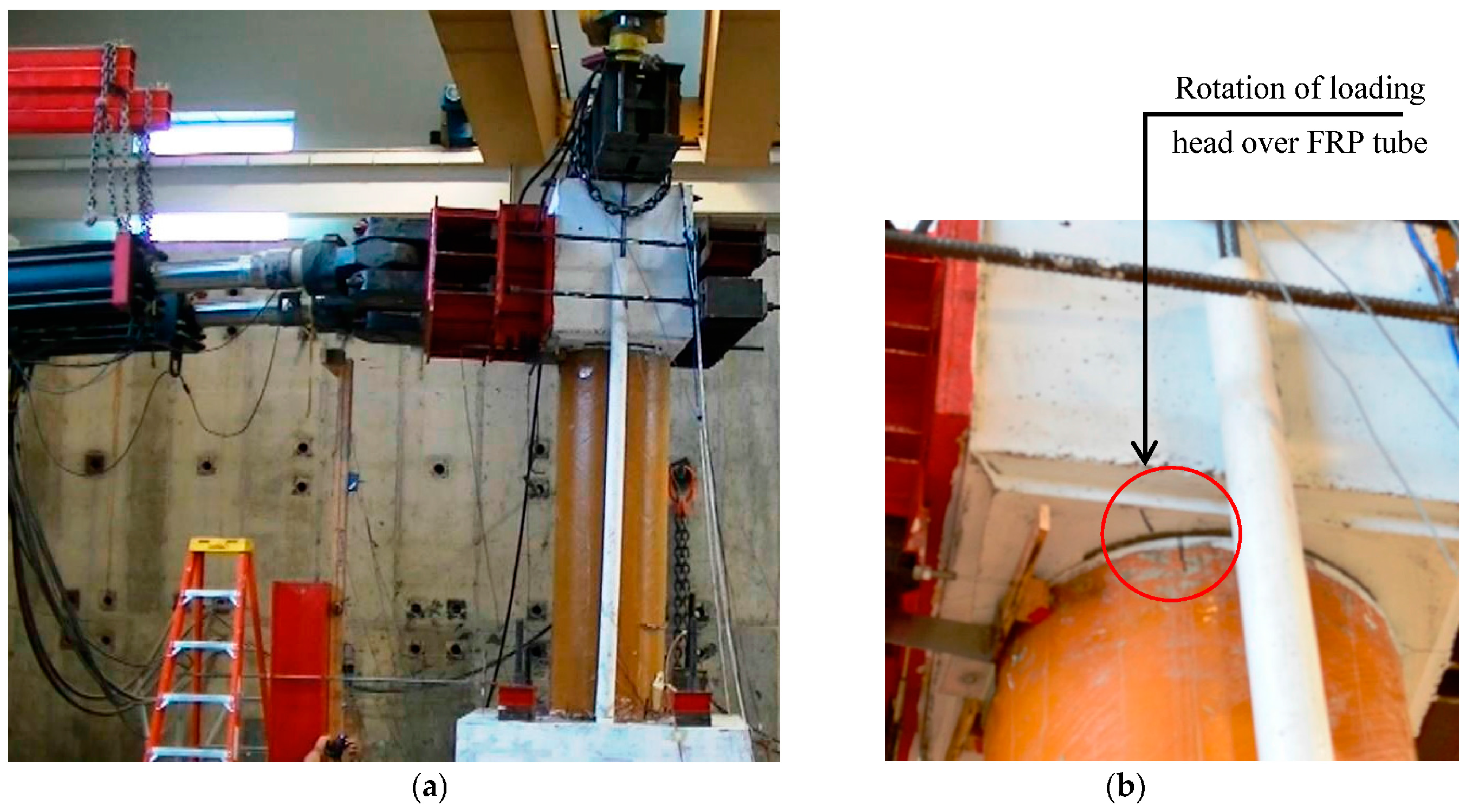
Figure 9.
Variation of the twist angle along the column height.
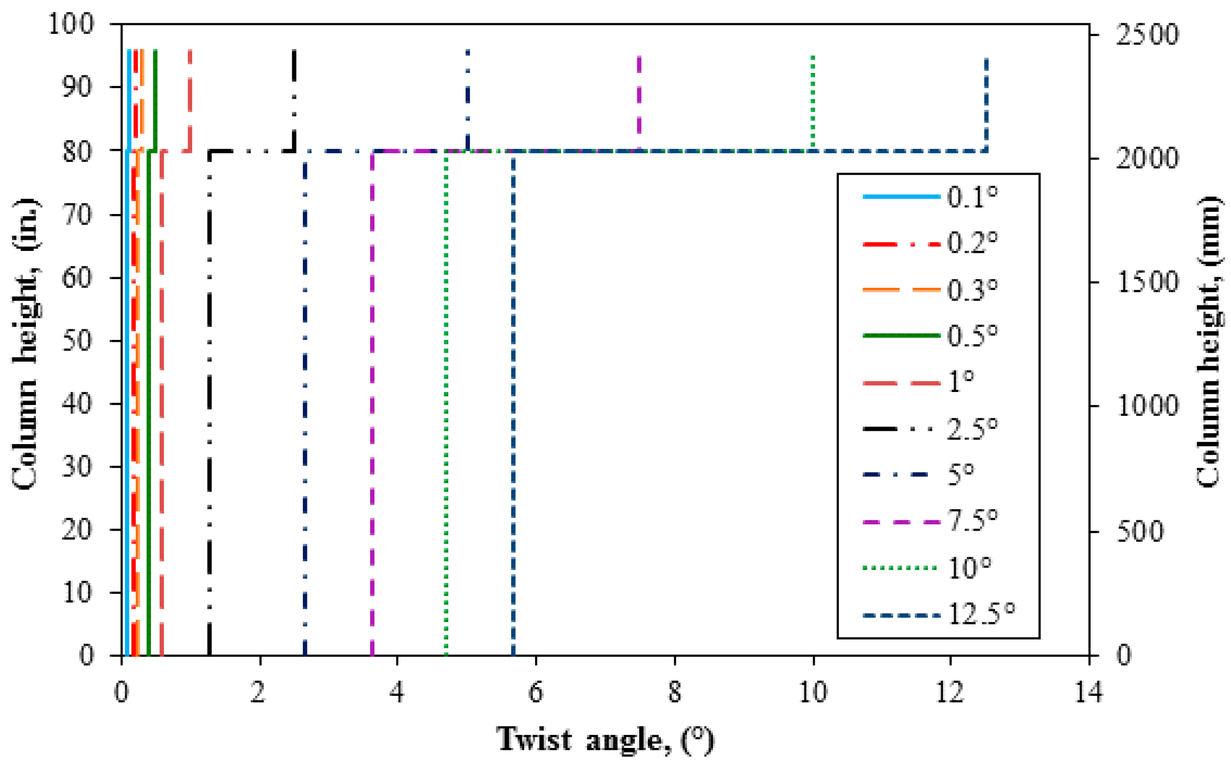
Figure 10.
Relative twist angle across different twist angles.

Figure 11.
Strain profile along the height of the column: (a) GFRP vertical (b) GFRP horizontal, (c) steel vertical, and (d) steel horizontal. * Scale was different.
Figure 11.
Strain profile along the height of the column: (a) GFRP vertical (b) GFRP horizontal, (c) steel vertical, and (d) steel horizontal. * Scale was different.
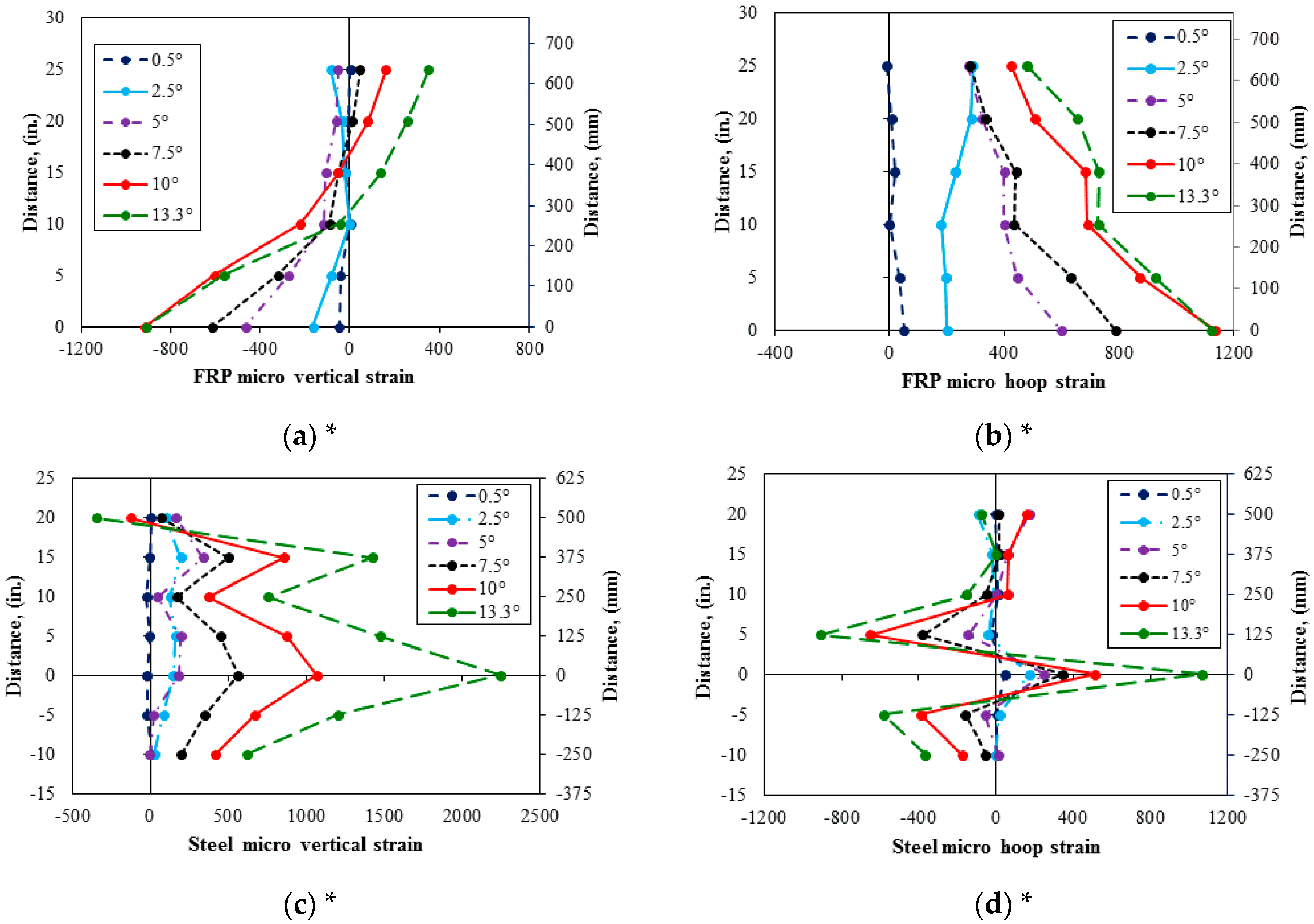
Figure 12.
Shear strain profile on the steel tube from the surface of the footing.
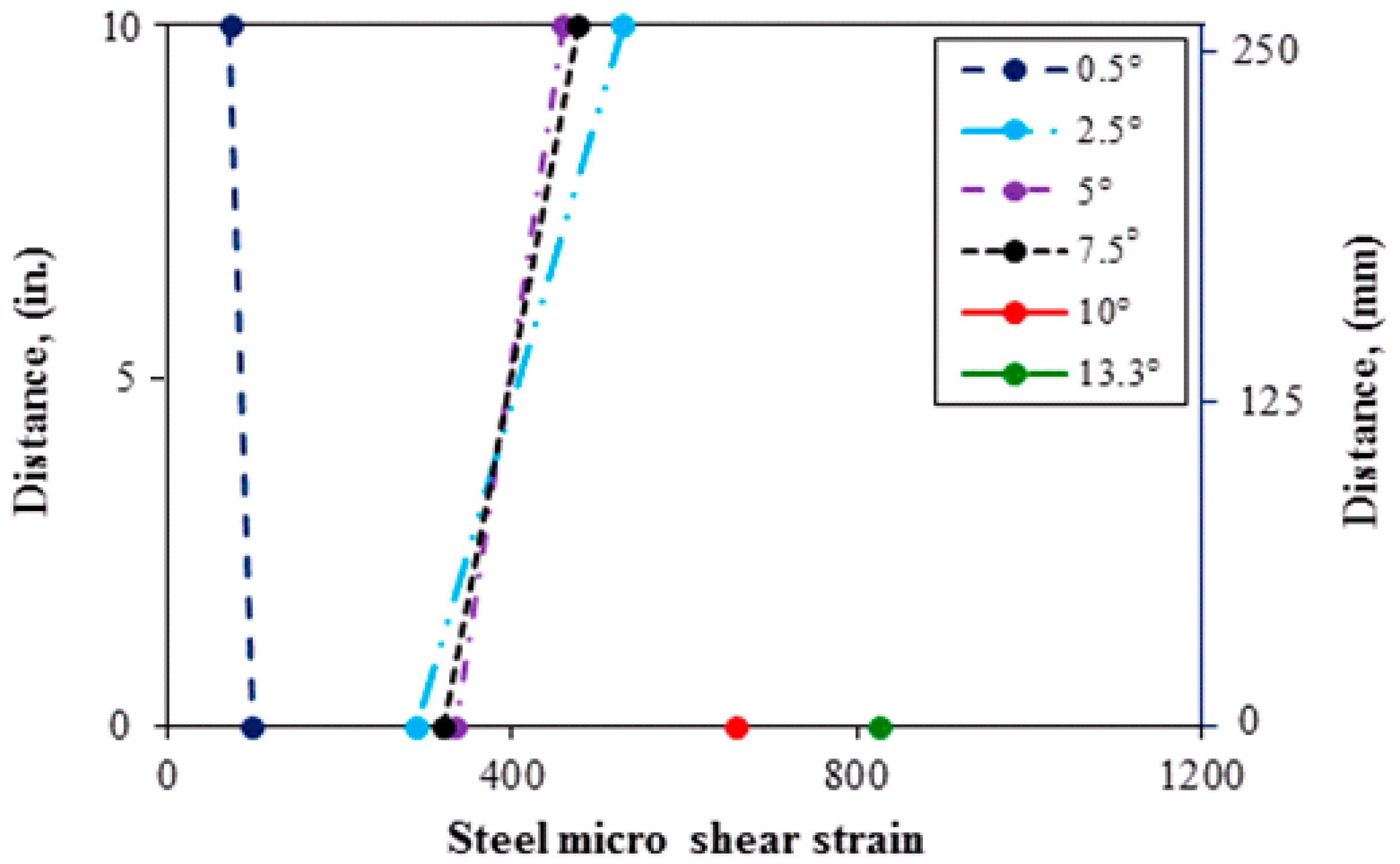
Figure 13.
Comparison of a HC-FCS column and a reinforced concrete column reproduced from Prakash [22].
Figure 13.
Comparison of a HC-FCS column and a reinforced concrete column reproduced from Prakash [22].


Table 1.
Mechanical properties of the glass fiber-reinforced polymer (GFRP) tube.
| Axial Compression Elastic Modulus, ksi (GPa) | Axial Ultimate Compressive Stress, psi (MPa) | Axial Tensile Elastic Modulus, ksi (GPa) | Axial Ultimate Tensile Stress, psi (MPa) | Hoop Elastic Modulus, ksi (GPa) | Hoop Rupture Stress, psi (MPa) |
|---|---|---|---|---|---|
| 677 (4.7) | 12,510 (83.8) | 1680 (11.6) | 9530 (65.7) | 3020 (20.8) | 40,150 (276.9) |
Table 2.
Mechanical properties of the steel tube.
| Yield Stress, psi (MPa) | Yield Strain | Ultimate Stress, psi (MPa) | Rupture Strain |
|---|---|---|---|
| 47,000 (324) | 0.16% | 70,000 (483) | 19.0% |
Table 3.
Concrete shell mixture properties.
| Cement, lb/yd3 (kg/m3) | Fly Ash, lb/yd3 (kg/m3) | Fine Aggregate, lb/yd3 (kg/m3) | Coarse Aggregate, lb/yd3 (kg/m3) | Water, lb/yd3 (kg/m3) | HRWR, lb/yd3 (kg/m3) | w/c Ratio |
|---|---|---|---|---|---|---|
| 590 | 170 | 1430 | 1430 | 380 | 1.9 | 0.5 |
| (350) | (101) | (848) | (848) | (225) | (1.13) |
Table 4.
Measured concrete strength.
| Property | Footing | Column |
|---|---|---|
| f’c, psi (MPa)—28 days | 9500 (65.5) | 5158 (35.5) |
| f’c, psi (MPa)—date of test | 9700 (66.9) | 6910 (51.0) |
© 2017 by the authors. Licensee MDPI, Basel, Switzerland. This article is an open access article distributed under the terms and conditions of the Creative Commons Attribution (CC BY) license (http://creativecommons.org/licenses/by/4.0/).
Share and Cite
MDPI and ACS Style
Anumolu, S.; Abdelkarim, O.I.; Abdulazeez, M.M.; Gheni, A.; ElGawady, M.A. Hollow-Core FRP–Concrete–Steel Bridge Columns under Torsional Loading. Fibers 2017, 5, 44. https://doi.org/10.3390/fib5040044
AMA Style
Anumolu S, Abdelkarim OI, Abdulazeez MM, Gheni A, ElGawady MA. Hollow-Core FRP–Concrete–Steel Bridge Columns under Torsional Loading. Fibers. 2017; 5(4):44. https://doi.org/10.3390/fib5040044
Chicago/Turabian StyleAnumolu, Sujith, Omar I. Abdelkarim, Mohanad M. Abdulazeez, Ahmed Gheni, and Mohamed A. ElGawady. 2017. "Hollow-Core FRP–Concrete–Steel Bridge Columns under Torsional Loading" Fibers 5, no. 4: 44. https://doi.org/10.3390/fib5040044
Note that from the first issue of 2016, this journal uses article numbers instead of page numbers. See further details here.