
Experimental and Analytical Modeling of GFRP Strengthened Grouted Mortarless Masonry Prisms

1
College of Civil Engineering, Hunan University, Changsha 410082, China
2
Department of Organic and Wood-Based Construction Materials, Technical University of Braunschweig, Hopfengarten 20, 38102 Braunschweig, Germany
3
Center for Light and Environmentally-friendly Structures, Fraunhofer Wilhelm-Klauditz-Institut, Bienroder Weg 54E, 38108 Braunschweig, Germany
4
College of Civil Engineering and Architecture, Qingdao University of Technology, Qingdao 266300, China
5
Anhui Institute of Civil Air Defense Building Research & Design, Hefei 230000, China
*
Author to whom correspondence should be addressed.
Fibers 2017, 5(2), 18; https://doi.org/10.3390/fib5020018
Submission received: 16 February 2017
/
Revised: 8 May 2017
/
Accepted: 10 May 2017
/
Published: 12 May 2017
(This article belongs to the Special Issue Fibers and Techniques for Upgrading of Concrete and Masonry Constructions)
Abstract
:The compressive performance of grouted mortarless masonry prisms strengthened with glass fiber-reinforced polymer (GFRP) composites was investigated in this study. A total of 18 grouted mortarless masonry specimens, i.e., nine strengthened with GFRP (called G-GMM) and nine without GFRP (called GMM), were tested under uniaxial compression. The effect of grout strength on the compressive strength of the prisms was discussed. Moreover, the effect of GFRP on the cracking load, modulus of elasticity, ultimate bearing capacity, failure modes, compressive stress–strain behavior, and deformation behavior of the specimens was analyzed. The test results indicated that GFRP strengthening increased the ratio of initial cracking load and ultimate load bearing capacity of mortarless masonry to a great extent, i.e., the ratio is 50–80% for G-GMM and 40–65% for GMM. In addition, GFRP clearly improved the deformation capability of the GMM. The tested experimental data were in good agreement with the predicted values using classic expressions.
1. Introduction
Masonry has been widely used in structural application due to its typical compressive strength. The compressive strength of masonry is one of the critical characteristics of designing masonry structure, and it depends on several parameters such as mortar strength, grouting, grout strength, and bond pattern [1,2]. Nowadays, there is an increasing tendency to use grouted mortarless masonry (GMM) because of its advantages, such as: (1) simple and fast construction technology, (2) small effect on construction environment, and (3) the quality of masonry construction being unaffected by mortar [3,4,5]. Some scholars studied mortarless masonry and found that grout enhanced strength, stiffness, and stability of mortarless prisms. Grout did not only restrict the initial deformation of mortarless masonry, but also improved its ultimate load capacity to a great extent [6,7], and compared the compressive behavior of grouted mortarless masonry and the ungrouted mortarless prisms. They found that the variations in strength and deformation in grouted specimens were higher than those in ungrouted specimens [8].
For many years, strengthening using external confinement has been considered an effective technique to upgrade or retrofit existing reinforced concrete and masonry compressive column components [9]. Recently, Fiber Reinforced Polymers (FRP) have been widely researched and used in strengthening and retrofitting engineering structures to increase the carrying capacity or ductility because of their significant characteristics such as high strength and increased deformation capability [10,11,12,13], and there are lots of functional analytical models for better understanding and explanation for FRP confinement [14,15].
FRP used in masonry repairing and restraining performs several advantages such as high strength-to-weight ratio, ease of application in terms of labor and time, decreased curing time, and minimal interference with existing architecture of the structure [16,17,18,19,20,21,22], and has been considered in application of seismic masonry walls [23,24]. The FRP confinement increased load-carrying capacity and deformability of masonry nearly linear with an increase in average confining stress [25]. The debonding between masonry and FRP has been researched and one energy balance approach was proposed to analyze the debonding process of FRP strengthened masonry structures [26,27]. Design formulas for modeling the FRP strengthened and rehabilitation masonry have been proposed [28,29].
Among the disadvantages of traditional construction techniques of masonry structure, the complicated construction processes require workers possessing good construction skills and have other requirements such as good construction environment and high maintenance. Due to heavy weight and frangibility of masonry materials, masonry typically possesses low tensile strength, shear strength, and flexural strength. In addition, the integrity and seismic performance of masonry structures are poor. Thus, grouted mortarless masonry strengthened with GFRP has the potential for wide applications in the field of civil engineering due to the improved structural performance coming from GFRP confinement. To date, in the literature, studies on grouted mortarless masonry reinforced with glass fiber-reinforced polymer (GFRP) are very rare. Therefore, the effects of grouted strength and GFRP strengthening on the compressive behavior of masonry were systematically investigated in this study. The experimental results presented in this study will be used as the references for the following studies on large-scale grouted mortarless masonry columns.
2. Experimental Research
2.1. Material and Specimen Fabrication
Full grouted bricks, with a dimension of 390 mm (Length) × 190 mm (Width) × 190 mm (Height) and a thickness of 30 mm, were used for the study (Figure 1). The mean compressive strength of the bricks was 16.8 MPa, which was the mean value of five tested brick specimens in the mechanical tests (GB50003-2011 [30]). The standard deviation was 0.4 MPa. Three different grouted mixes (i.e., GN1, GN2, and GN3) were designed and constructed to investigate the effect of grouted concrete strength on the compressive strength of the prisms. Grouted concrete strength was obtained from the testing on three 150 × 150 × 150 mm3 air-cured cubes following GB50081-2002 [31]. The average strength of the three grout types (i.e., GN1, GN2, and GN3) were 23.9 MPa, 34.7 MPa, and 45.0 MPa, respectively, and their standard deviations were 1.37 MPa, 0.54 MPa, and 1.03 MPa, respectively. For GFRP strengthened GMM specimens, the mechanical properties of GFRP and epoxy are listed in Table 1 and Table 2, respectively. E-glass unidirectional fibers were selected as the confinement and the properties of glass fibers are provided in Table 1 from the producer, where the nominal thickness was for the dry fibers, with a density of 414 g/m2.
A total of 18 masonry prisms were constructed in running bonds with full bedding. The variables included the grouted concrete strength and GFRP stripe reinforcement. The surface of all the bricks was polished. Then, three layers of bricks were stacked on a 30 mm-thick concrete floor hole-to-hole, and then grouted concrete was poured and vibrated after flatness check. The unidirectional glass fiber fabrics were firstly cut into appropriate lengths based on the arrangement of layers. The glass fabrics were impregnated with epoxy and then applied on the two adjacent joints between prisms. The radial direction of unidirectional glass fiber was perpendicular to the loading direction. The overlap length of GFRP was 150 mm to avoid the premature failure. Grouting was performed a week later when the hollowed prisms were cured. The grout cubes and the prisms were cured at 20 °C at a relative humidity over 85% for 28 days. Before testing, the specimens were capped with a 10 mm-thick cement mortar to screed.
The unstrengthened and GFRP-strengthened GMM specimens are shown in Figure 2. The 18 specimens were categorized into three groups based on the grouted concrete strength and marked as AG1–AG3, A1–A3; BGl–BG3, B1–B3; and CGl–CG3, C1–C3 based on the GFRP strengthened or not. A, B, and C denote specimens with grouting strengths of 23.9, 34.7, and 45.0 MPa, respectively. G indicates specimens strengthened with GFRP as Table 3.
2.2. Test Setup and Method
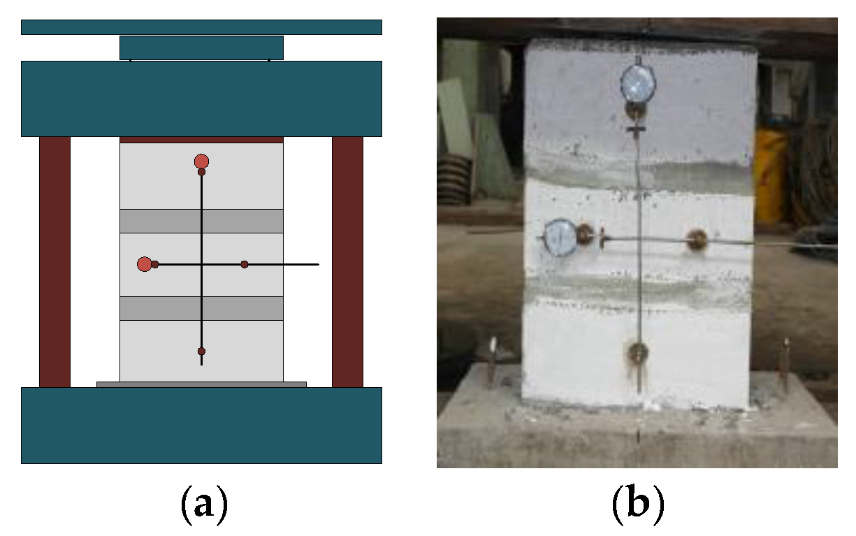
The specimens were tested under axial compressive load using a 5000 kN compression testing machine as Figure 3a and the indicators were used to record the lateral and longitudinal strains of the masonry prisms in Figure 3b, located along the longitudinal and horizontal medians, respectively. The scaling loading method was applied by 50 kN/each scale and the loading rate used was 1 kN/s according to GB/T 50129-2011 [32]. The bearing capacity of each load level, as well as the vertical and horizontal readings of the dial indicators, were recorded during the loading process. When the first crack appeared, loading was suspended immediately in order to record the first cracking load Ncr. Then, the test machine was reloaded until failure of the specimen.
3. Results and Discussion
3.1. Failure Modes
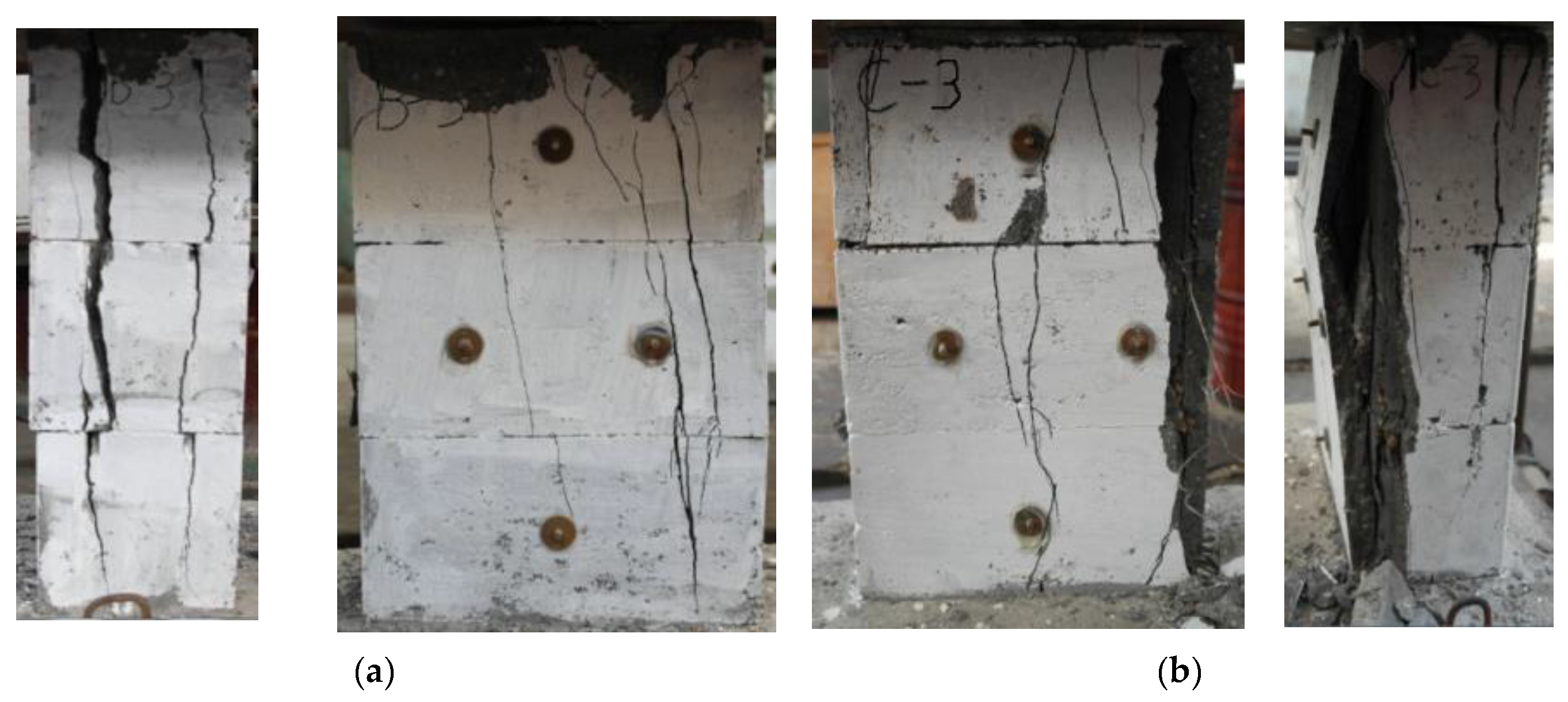
For unstrengthened specimens, the initial vertical cracks appeared at the top of the flank of the brick shell with cracking load of 40–65% of the ultimate load, and the cracks wouldn’t develop without continued loading. The cracks extended uniformly upward and downward with the loading increasing and went through 1–2 bricks with a load of 80–90% of the ultimate load, and the cracks developed even without loading. The vertical cracks became wider and longer rapidly throughout the masonry until rupture due to the loss of stability. The failure modes of the unstrengthened specimens presented two types of cracking patterns, i.e., failure mode 1 and failure mode 2, as shown in Figure 4, which appeared randomly. The bricks ruptured firstly with many cracks throughout and the grouted concrete bore more loading and ruptured due to the less stiffness of masonry in failure mode 1. In failure mode 2, the grouted concrete core ruptured firstly to aggravate the deformation, and then the outer layer of the brick ruptured.
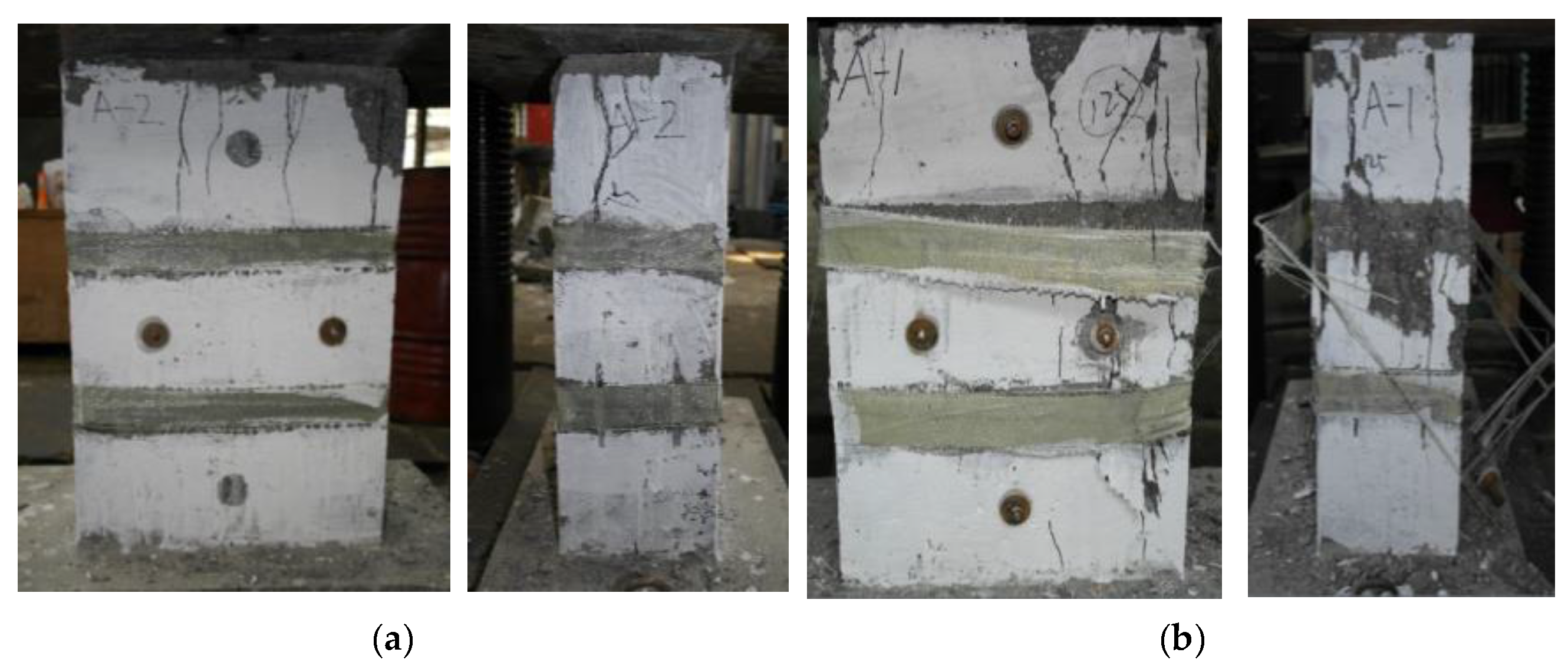
For the GFRP strengthened specimens, the initial cracks appeared when the load was approximately 50–80% of the ultimate bearing capacity, but had the same cracking distribution as the unstrengthened specimens in which the confinement of GFRP has been activated sufficiently. With the increasing of loading, the cracks developed wider and deeper, but have not been through the masonries with a load of 70–90% ultimate carrying capacity. At the end, the GFRP strengthened specimens failed in two ways, namely, failure mode 1 as shown in Figure 5a (i.e., the masonry crushed and cracks passed through, but GFRP did not peel off from the masonry or rupture) and failure mode 2 as shown in Figure 5b (i.e., GFRP fractured or peeled off and the masonry damaged). Compared to unstrengthened specimens, the integrity of the masonry was improved without the outside surface of masonry collapsing, and the GFRP confinement has improved the deformation capability of the GMM remarkably.
3.2. Tested Results and Analysis
The compressive parameters, i.e., the initial cracking load, ultimate load, ultimate stress, failure modes of the specimens obtained from the test are provided in Table 4, and the tested results were compared with the standard calculated values. The calculated compressive strength fg,m of grouted masonry prisms is calculated as Equation (1) according to GB50003-2011 [30]:
where = average compressive strength of the prisms, = average compressive strength of the masonry, = average compressive strength of grouted concrete cubes, = average compressive strength of the single block, = average compressive strength of the mortar, and = 0, and = ratio between the square hole area and the gross area of the block:
where = initial cracking strength of the prisms, = initial cracking load of the prisms, = compressive strength of the prisms, and = compressive load of the prisms.
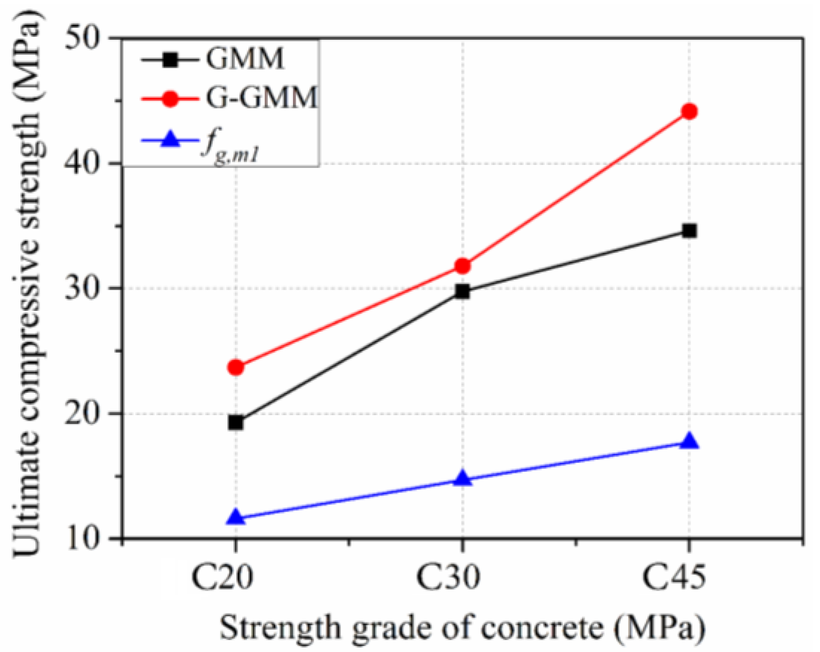
Table 4 shows that the application of GFRP confinement increased the ratio of initial cracking load to the ultimate bearing capacity of the mortarless masonry to a great extent, i.e., 40–65% for the unstrengthened ones and 50–80% for the strengthened ones, respectively. Based on Section 3.1, the failure modes of all of the specimens were divided into three categories: (1) X-type: continuous cracks appeared longitudinally on the front view of the specimen, (2) Y-type: bricks crushed totally, and (3) Z-type: the hoop GFRP fractured and peeled off from the masonry, and each of the specimens were marked as different failure modes in Table 4. For the average compressive strength of the specimens in three groups, the compressive strength of the strengthened specimens with different grouted mixes was improved compared with unstrengthened groups, with the largest improvement up to 27.6% (i.e., for the average compressive strength of the prisms in group 3, from 34.60 MPa for unstrengthened specimens to 44.16 MPa for strengthened specimens). With the increasing of grouted concrete strength, the unstrengthened specimens showed a parabolic relationship with the highest strength of the B1-3 group, but, with the confinement of GFRP jackets, the strength and the effectiveness of GFRP confinement demonstrated an increasing tendency for higher grouted concrete strength. The presence of GFRP may not lead to a significant enhancement of the carrying capacity of the masonry, but, in the intermediate case, a visible advantage was visible in terms of first cracking load, which was delayed by the GFRP action. However, the ultimate bearing capacity of both the strengthened ones and the unstrengthened ones were higher than the standard calculated values of ordinary masonry, as shown in Figure 6.
3.3. Axial Compressive Stress–Strain Behavior
The compressive stress–strain curves of the three tested groups are shown in Figure 7, respectively, which showed a bilinear behavior. At the initial stage of stress–strain curves where the compressive strains were below 500 , all of the stress–strain curves in each group with different grouted mix strengths showed very similar linear stress–strain behavior in which the GFRP confinement had not been activated and the load was mostly carried by masonry, especially in the group with the grouted concrete strength of 34.7 MPa. When the strain exceeds 500 , the GFRP confinement was activated and the stress–strain behavior performed an elastic-plastic curve, which showed smaller stress–strain curve slopes and indicated that the deformation was restrained by the loop GFRP jackets and better ductility was performed. The strains at the ultimate stress were significantly larger in the GFRP strengthened specimens than unstrengthened ones and the effectiveness of the GFRP external strengthening was more evident in those specimens with the highest grouting strength.
Based on experimental studies, using Equation (5) presented by Zeng et al. [33], the elastic modulus and stability coefficient of the specimens can be easily derived:
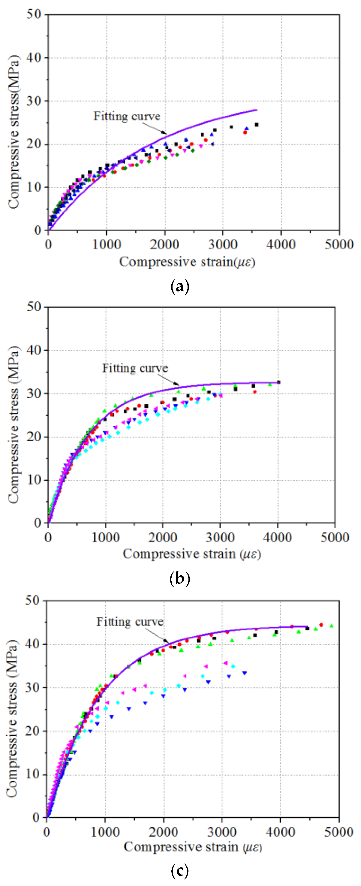
where = strain of grouted prisms, = stress of grouted prisms, = average compressive strength of the masonry, and = elastic characteristic value of the block type and the strength of the mortar. is the only undetermined coefficient in Equation (5). In this paper, the logarithmic constitutive relation was used to fit the stress–strain behavior in this research according to the characteristics of the stress–strain curves. By fitting the experimental data, = 216, = 267, = 182 of Equation (5) could be assessed for the three types of grouted mixes, i.e., GN1, GN2, and GN3, respectively. The comparison of the tested values and the fitting curves from models of Zeng et al. [33] are shown in Figure 8.
The fitting compressive stress–strain curves of the tested specimens are similar to the tested stress–strain curves, which consist of three stages, i.e., the pseudo-elastic stage, the elastic-linear stage and the post-linear stage. This phenomenon indicates the confinement mechanism clearly in the first linear stage, the transverse deformation of masonry was not apparent and the GFRP confinement was activated, carried mostly by bricks and the grouted concrete. Then, with the increasing of load, the development of loop expansion started to activate the GFRP confinement and presented the linear-elastic transition stage where the GFRP restrained the loop deformation, and both the masonry and GFRP jackets carried the load in this situation, and, at the end, the GFRP jacket ruptured and the masonry and concrete core were crushed, which performed a short linear stage, whereas the final linear stages were an ideal situation.
3.4. Confinement Mechanism of GFRP Strengthened Mortarless Masonry
Under compression, GFRP strips were used to confine the lateral deformation of the mortarless masonry to increase the deformation capability of a single brick. In addition, the ultimate load-bearing capacity and deformation capacity of the prisms were improved because the core area of the masonry was under a tri-axial compressive stress state as a result of GFRP confinement. In terms of axial loading, the G-GMM expanded with lateral deformation, placing GFRP under tension. The masonry core area was mainly squeezed inward and was bound from four corners. The lateral restraint provided by GFRP can be divided into two areas. The first was the effective restraint area, where the masonry was forced in a diagonal direction by the squeeze constraint stress and the masonry was in a tri-axial stress state; thus, the compressive strength and deformation properties of the specimens were improved. The second was a non-effective area, in which the lateral restraint stress was small and had a marginal effect on the compressive strength and deformation of the specimens.
In this study, GFRP was applied over horizontal joints between two adjacent bricks in equidistant form. The maximum lateral restraint effect on the mortarless masonry was found in the applied GFRP area, whereas the minimal effect was observed in the middle region of the adjacent GFRP, which determined the ultimate compressive strength of the G-GMM. As shown in the compressive failure modes of the G-GMM, the destruction of the specimens mainly occurred in the four corners of the masonry without GFRP, which is similar to the condition in the case of a concrete column confined with GFRP. Homogenizing assumptions can be feasibly made for the GMM, and the basic theory of concrete column reinforced with GFRP would be appropriate for analysis of G-GMM.
3.5. Effective Restraint Area of GFRP Strengthened Masonry
The effectiveness of the lateral GFRP jacket restraint is highly dependent on the cross-sectional shape of the masonry. For the circular GFRP-confined concrete under axial compression, the lateral deformation as well as the lateral confining pressure of the concrete were uniform. The effective confinement region was the entire cross section of the concrete cylinder. However, in the case of the GFRP-confined concrete with a rectangular cross section, the lateral deformation of the concrete under compression was not uniform because of the higher rigidity in the diagonal direction and the smaller FRP deformation. The deformation near the midpoint of the four sides of the rectangular cross section was larger because of the weak flexural rigidity of concrete and the minimal confining effect on the prism.
Based on the model proposed by Liu et al. [34], in accordance with American Concrete Institute ACI 440.2R-08 code [35], the active restraint area of the rectangular cross section is calculated as below:
where = effective constraint area of the rectangular cross section; and = width and height of the rectangular cross section, respectively; and = radius of chamfering.
3.6. Carrying Capacity of GFRP Strengthened Masonry
The deformation difference between the grouted concrete and the brick was ignored when analyzing the compressive bearing capacity of the grouted concrete masonry theoretically. The analysis method for FRP-confined concrete columns was referred to for better understanding of carrying capacity of GFRP strengthened masonry. Based on the analyzed method of the lateral confining pressure of FRP on the concrete cylinders, an equivalent-diameter method was adopted to establish the calculation method of the lateral restraint pressure from GFRP on the mortarless masonry.
The constitutive relation of the confined system was related to the ultimate compressive strength of concrete , the corresponding peak strain , and the lateral restraint stress . Thus, one dimensionless figure of was defined as the GFRP eigenvalue as expressed below:
where = volume reinforcement ratio of GFRP, and = effective tensile stress of GFRP under the ultimate load of the specimen. Toutanji [36] and Saafi et al. [37] proposed the following constitutive relations:
where = ultimate compressive strength of unconstrained concrete, and = peak strain of unconstrained concrete. The lateral restraint stress from GFRP to the circular column was uniform and continuous according to the preceding analysis. The lateral binding of the circular cross-section column is calculated as follows:
where = lateral binding of the circular cross-section column, = modulus of elasticity of GFRP, = strain of GFRP under the ultimate limit state of the structure, = thickness of GFRP, and = diameter of the circular cross-section column.
For the GFRP-confined rectangular column, the effective restraint stress of the mortarless masonry is calculated as follows to determine effective restraint stress [38]:
where = cross-sectional sharp impact factor, = effective constraint area, and = total area reinforced with GFRP. According to Lam and Teng [39], the diameter of the circular cross-section column in Equation (10) can be written as follows:
In summary, the effective restraint stress of the rectangular cross-section column is shown as follows:
In this study, the compressive strength of the G-GMM used a classical expression by Richart et al. [40],
where = ultimate compressive strength of the GMM, = ultimate compressive strength of the G-GMM, and = effective coefficient of the lateral restraint stress. The lateral restraint stress of the G-GMM and the experimental data are shown in Table 5.
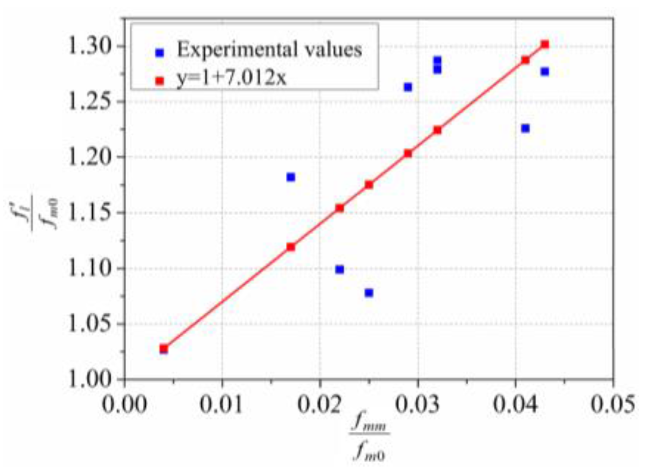
As shown in Table 5, the lateral restraint stress of specimens AG-2 and BG-2 was small because GFRP did not rupture when the specimens failed and the deformation of the specimen was small. =7.012 can be calculated using the least squares method according to the data in Table 4. The comparison of the experimental values (listed in Table 4) and the predicted values based on fitting are given in Figure 9.
4. Conclusions
This study investigated the compressive behavior of grouted mortarless masonry reinforced with GFRP jackets. Experimental parameters such as the strength of grouted concrete and FRP reinforcement were investigated. The theory of FRP-confined concrete was referred to in order to model the behaviour of FRP strengthened grouted mortarless masonry. The following conclusions could be drawn:
- Like the FRP-confined concrete, the GFRP confinement has improved the initial cracking load and ultimate carrying capacity of grouted mortarless masonry, which indicated that the GFRP confinement has restrained the crack development of masonry efficiently and increased the ultimate strain to improve the ductility of masonry system.
- The strength of grouted concrete has a parabolic influence on the ultimate carrying capacity of plain masonry strength but a positive effect on the ultimate carrying capacity of GFRP strengthened masonry. Unstrengthened masonry with different strengths of grouted concrete performed the same failure mode and stress–strain behaviour.
- The general compressive behaviour of GFRP strengthened grouted mortarless masonry was bilinear with an initial PSEUDO-elastic stage and an elastic-linear stage, while the slopes of the second stage at the stress–strain curves exhibit the trend of degression.
- The mechanism properties of GFRP strengthened grouted mortarless masonry was analyzed by homogenization according to FRP-confined concrete, which indicated that the stress concentration phenomenon existing at the corner of the masonry caused GFRP jackets to rupture mostly at the corner of masonry.
- One compressive stress–strain model was developed for the GFRP strengthened grouted mortarless masonry, which performed well to predict the experimental results.
Acknowledgments
The authors are grateful for the financial support from the National Natural Science Foundation of China (project code 51378193, 51408211), the Science and Technology Plan of Changsha (project code CSCG-HNTF-GK20130576), and the research fund supported by Hunan University. The author Chang Gao also acknowledges the master scholarship awarded by Hunan University.
Author Contributions
Liang Huang and Libo Yan conceived the project and designed the experiments. Liang Huang and Gao Ma directed the research. Chang Gao, Xiaoxi Li and Tianfeng Wang performed the experiments. Chang Gao, Xiaoxi Li and Libo Yan wrote the manuscript. All authors discussed the results and edited the manuscript.
Conflicts of Interest
The authors declare no conflict of interest.
References
- Huang, L.; Liao, L.; Yan, L.B.; Yi, H. Compressive strength of double H concrete block Masonry prisms. J. Mater. Civ. Eng. 2014, 50. [Google Scholar] [CrossRef]
- Ghobarah, A.; Galal, K. Out-of-plane strengthening of unreinforced masonry walls with openings. J. Compos. Constr. 2004, 8, 298–305. [Google Scholar] [CrossRef]
- Safiee, N.A.; Jaafar, M.S.; Alwathaf, A.H.; Noorzaei, J.; Abdulkadir, M.R. Structural behavior of mortarless interlocking load bearing hollow block wall panel under out-of-plane loading. Adv. Struct. Eng. 2011, 14, 1185–1196. [Google Scholar] [CrossRef]
- Waleed, A.; Thanoon, A.H.; Alwathaf, J.N.; Jaafar, S.; Abdulkadir, R. Nonlinear finite element analysis of grouted and ungrouted hollow interlocking mortarless block masonry system. Eng. Struct. 2008, 30, 1560–1572. [Google Scholar]
- Rekik, A.; Allaoui, S.; Gasser, A.; Blond, A.; Andreev, K.; Sinnema, S. Experiments and nonlinear homogenization sustaining mean-field theories for refractory mortarless masonry: The classical secant procedure and its improved variants. Eur. J. Mech. A/Solids 2015, 49, 67–81. [Google Scholar] [CrossRef]
- Waleed, A.; Thanoon, A.H.; Alwathaf, J.N.; Jaafar, S.; Abdulkadirc, R. Finite element analysis of interlocking mortarless hollow block masonry prism. Comput. Struct. 2008, 86, 520–528. [Google Scholar]
- Jaafar, S.; Waleed, A.; Thanoon, A.H.; Alwathaf, J.N.; Abdulkadir, R.; Ali, A.A. Strength correlation between individual block, prism and basic wall panel for load bearing interlocking mortarless hollow block masonry. Constr. Build. Mater. 2006, 20, 492–498. [Google Scholar] [CrossRef]
- Chaimoon, K.; Atttard, M.M. Experimental and numerical investigation of masonry under three-point bending. Eng. Struct. 2009, 31, 103–112. [Google Scholar] [CrossRef]
- Micelli, F.; De Lorenzis, L.; La Tegola, A. FRP-confined masonry columns under axial loads: analytical model andexperimental results. Masonry Int. J. 2004, 17, 95–108. [Google Scholar]
- Yin, P.; Huang, L.; Yan, L.B.; Zhu, D. Compressive behavior of concrete confined by CFRP and transverse spiral reinforcement. Part A: Experimental study. Mater. Struct. 2016, 49, 1001–1011. [Google Scholar] [CrossRef]
- Huang, L.; Sun, X.X.; Yan, L.B.; Zhu, D. Compressive behavior of concrete confined with GFRP tubes and steel spirals. Polymers 2015, 7, 851–875. [Google Scholar] [CrossRef]
- Gao, C.; Huang, L.; Yan, L.B.; Kasal, B. Behavior of glass and carbon FRP tube encased recycled aggregate concrete with recycled clay brick aggregate. Compos. Struct. 2016, 155, 245–254. [Google Scholar] [CrossRef]
- Gao, C.; Huang, L.; Yan, L.B.; Ma, G. Compressive behavior of CFFT with inner steel wire mesh. Compos. Struct. 2015, 133, 322–330. [Google Scholar] [CrossRef]
- Huang, L.; Gao, C.; Yan, L.B.; Kasal, B. Confinement models of GFRP-confined concrete: Statistical analysis andunified stress–strain models. J. Reinf. Plast. Compos. 2016, 35, 867–891. [Google Scholar] [CrossRef]
- Huang, L.; Gao, C.; Yan, L.B.; Kasal, B.; Ma, G. Reliability assessment of confinement models of carbon fiber reinforced polymer-confined concrete. J. Reinf. Plast. Compos. 2016, 35, 996–1026. [Google Scholar] [CrossRef]
- Yan, L.; Chouw, N.; Jayaraman, K. On energy absorption capacity, flexural and dynamic properties of flax/epoxy composite tubes. Fiber. Poly. 2014, 15, 1270–1277. [Google Scholar] [CrossRef]
- Yan, L.B. Plain concrete cylinders and beams externally strengthened with natural flax fabric reinforced epoxy composites. Mater. Struct. 2016, 49, 2083–2095. [Google Scholar] [CrossRef]
- Micelli, F.; Di Ludovico, M.; Balsamo, A.; Manfredi, G. Mechanical behaviour of FRP-confined masonry by testing of full-scale columns. Mater. Struct. 2014, 47, 2081–2100. [Google Scholar] [CrossRef]
- Aiello, M.; Micelli, F.; Valente, L. FRP confinement of square masonry columns. J. Compos. Constr. 2014, 13, 148–158. [Google Scholar] [CrossRef]
- Basilio, I.; Fedele, R.; Lourenço, P.B.; Milani, G. Assessment of curved FRP-reinforced masonry prisms: Experiments and modeling. Constr. Build. Mater. 2014, 51, 492–505. [Google Scholar] [CrossRef]
- Fossetti, M.; Minafo, G. Comparative experimental analysis on the compressive behaviour of masonry columns strengthened by FRP, BFRCM or steel wires. Composites Part B 2017, 112, 112–124. [Google Scholar] [CrossRef]
- Malena, M.; Focacci, F.; Carloni, C.; de Felice, G. The effect of the shape of the cohesive material law on the stress transfer at the FRP-masonry interface. Composites Part B 2014, 110, 368–380. [Google Scholar] [CrossRef]
- Zhang, S.; Yang, D.; Sheng, Y.; Garrity, S.W.; Xu, L.H. Numerical modelling of FRP-reinforced masonry walls under in-plane seismic loading. Constr. Build. Mater. 2017, 134, 649–663. [Google Scholar] [CrossRef]
- Sadek, H.; Lissel, S. Seismic performance of masonry walls with GFRP and Geogrid Bed joint reinforcement. Constr. Build. Mater. 2013, 41, 977–989. [Google Scholar] [CrossRef]
- Krevaikas, T.D.; Triantafillou, T.C. Masonry confinement with fiber-reinforced polymers. J. Compos. Constr. 2014, 9, 128–135. [Google Scholar] [CrossRef]
- Freddi, F.; Sacco, E. Debonding process of masonry element strengthened with FRP. Procedia Eng. 2015, 109, 27–34. [Google Scholar] [CrossRef]
- Carloni, C.; Focacci, F. FRP-masonry interfacial debonding: An energy balance approach to determine the influence of the mortar joints. Eur. J. Mech. A/Solids 2016, 55, 122–133. [Google Scholar] [CrossRef]
- Carrara, P.; Freddi, F. Statistical assessment of a design formula for the debonding resistance of FRP reinforcements externally glued on masonry units. Composites Part B 2014, 66, 65–82. [Google Scholar] [CrossRef]
- Grande, E.; Milani, G. Modeling of FRP-strengthened curved masonry specimens and proposal of a simple design formula. Compos. Struct. 2016, 158, 281–290. [Google Scholar] [CrossRef]
- Ministry of Development of the People’s Republic of China. Code for Design of Masonry Structures. GB50003-2011; China Planning Press: Beijing, China, 2011.
- Ministry of Development of the People’s Republic of China. Standard for Test Method of Mechanical Properties on Ordinary Concrete; GB/T 50081-2002; China Planning Press: Beijing, China, 2002.
- Ministry of Development of the People’s Republic of China. Standard for Test Method of Basic Mechanical Properties of Masonry; GB/T 50129-2011; China Planning Press: Beijing, China, 2011.
- Zeng, X.M.; Yang, W.J.; Shi, C.X. Study of consititution relationship model for compressive masonry. Build. Sci. Res. Sichuan 2001, 27, 8–10. [Google Scholar]
- Liu, T.; Feng, W.; Zhan, Z.M.; Wei, G.F. A study on the compressive performance of rectangular concrete columns confined with CFRP sheets. China Civ. Eng. J. 2006, 39, 41–47. [Google Scholar]
- ACI 440.2R-08. Guide for the Design and Construction of Externally Bonded FRP Systems for Strengthening Concrete Structures; American Concrete Institute: Farmington Hills, MI, USA, 2008. [Google Scholar]
- Toutanji, H.A. Stress-strain characteristics of concrete columns externally confined with advanced fiber composite sheets. ACI Mater. J. 1999, 96, 397–404. [Google Scholar]
- Saafi, M.; Toutanji, H.A.; Li, Z. Behavior of concrete columns confined with fiber-reinforced polymer tubes. ACI Mater. J. 1999, 96, 500–509. [Google Scholar]
- Zhao, T.; Xie, J.; Liu, M.G.; Dai, Z.Q. Research on new method of improving properties of high strength concrete by using continuous carbon fiber sheet. Ind. Const. 2001, 31, 42–44. [Google Scholar]
- Lam, L.; Teng, J.G. Compressive strength of FRP-confined concrete in rectangular columns. In Proceedings of the International Conference on FRP Composites in Civil Engineering, Hong Kong, China, 12–15 December 2001; Volume 1, pp. 335–343. [Google Scholar]
- Richart, F.E.; Brandtzæg, A.; Brown, R.L. A Study of the Failure of Concrete under Combined Compressive Stresses; Technical Report; University of Illinois at Urbana Champaign College of Engineering Experiment Station: Champaign, IL, USA, 1928. [Google Scholar]
Figure 1.
Brick dimensions (unit: mm).
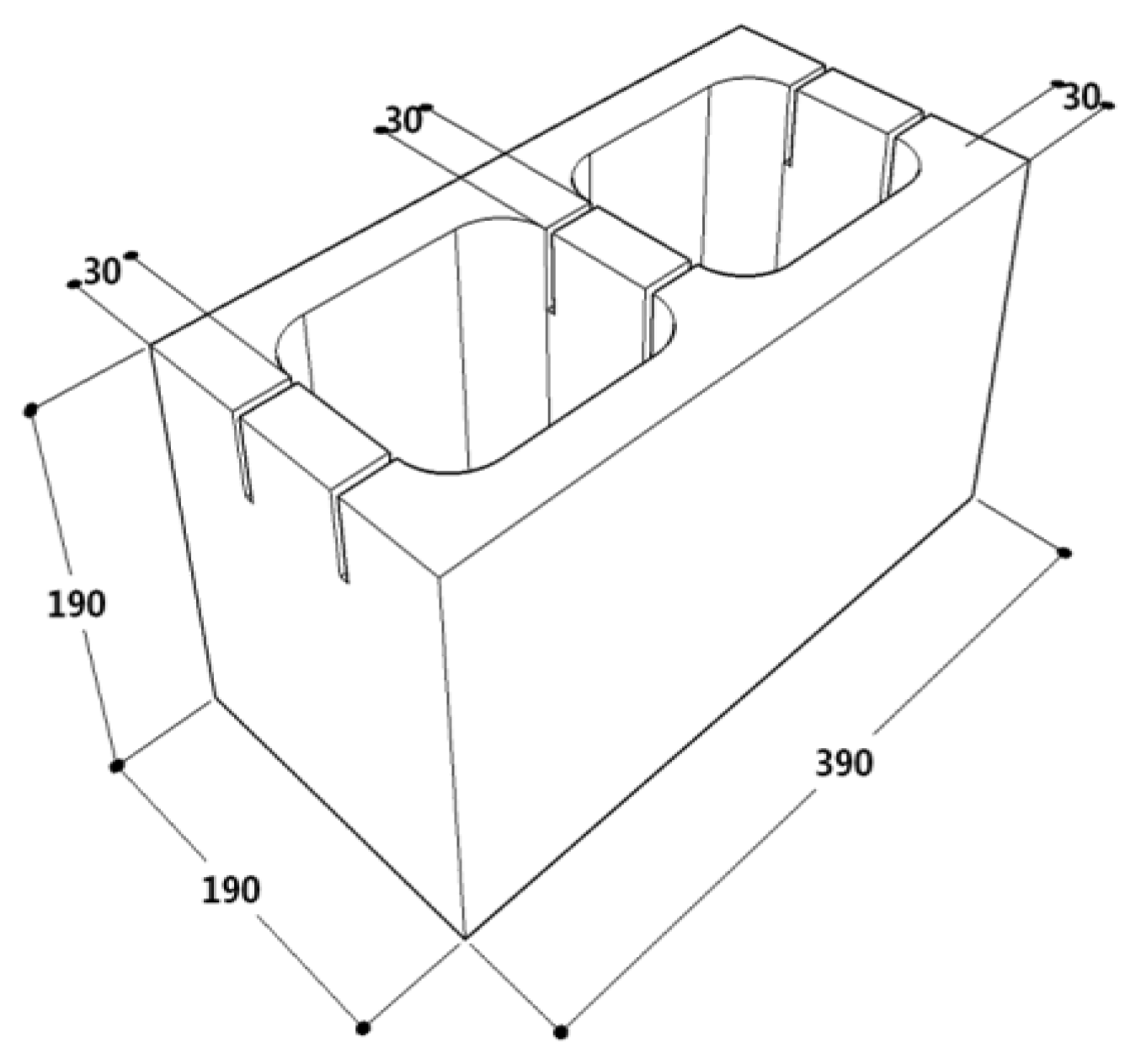
Figure 2.
Size of compression specimen (unit: mm).
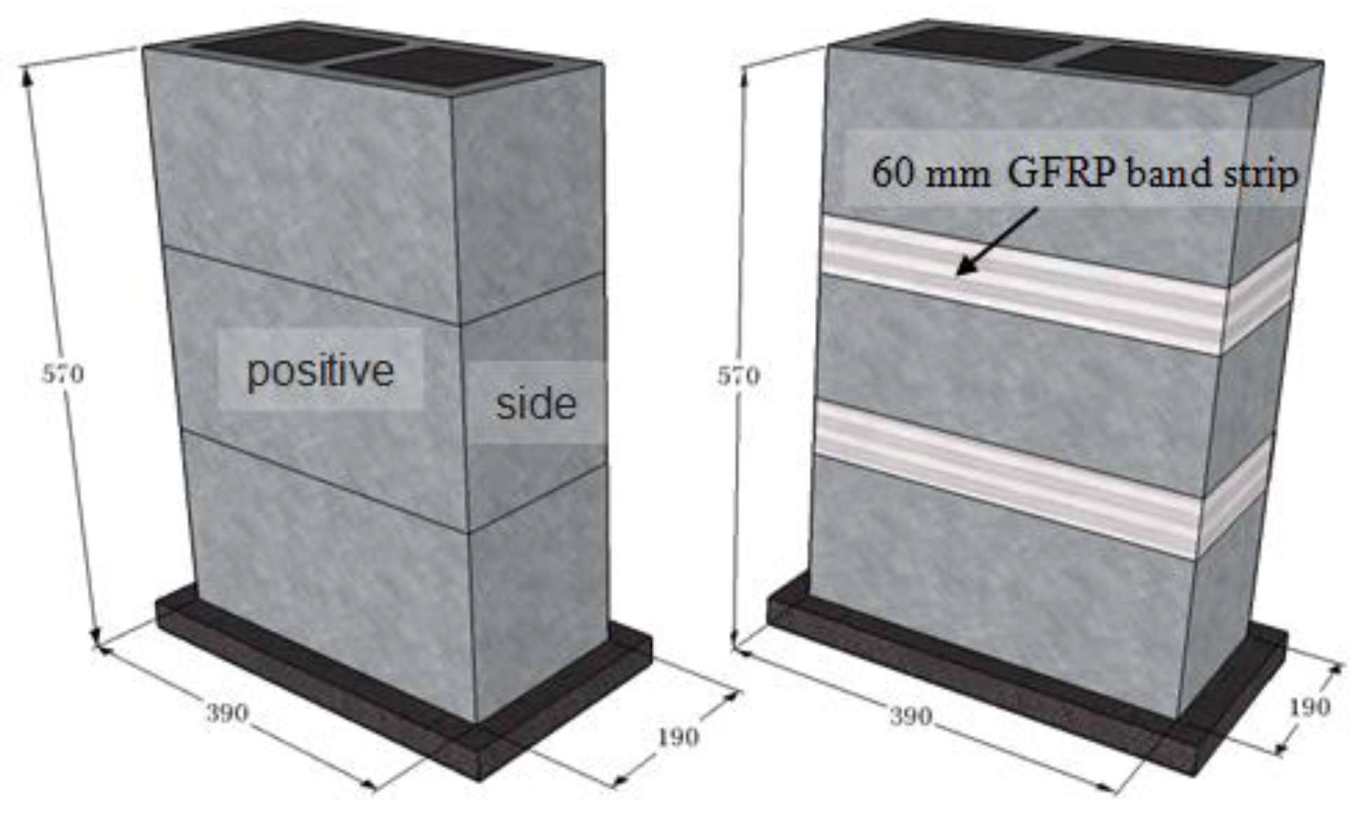
Figure 3.
(a) test setup; (b) specimen with dial indicators.

Figure 4.
Typical compressive failure modes of the unstrengthened specimens: (a) failure mode 1 (Specimen B-3); (b) failure mode 2 (Specimen C-3).
Figure 4.
Typical compressive failure modes of the unstrengthened specimens: (a) failure mode 1 (Specimen B-3); (b) failure mode 2 (Specimen C-3).

Figure 5.
Compressive failure modes of the G-GMM specimen: (a) failure mode of the masonry; (b) failure mode of glass fiber-reinforced polymer (GFRP).
Figure 5.
Compressive failure modes of the G-GMM specimen: (a) failure mode of the masonry; (b) failure mode of glass fiber-reinforced polymer (GFRP).

Figure 6.
Comparison of the ultimate compressive strength of the specimens.

Figure 7.
Compressive stress–strain curves of the specimens with grouting strengths of (a) 23.9 MPa; (b) 34.7 MPa; (c) 45.0 MPa.
Figure 7.
Compressive stress–strain curves of the specimens with grouting strengths of (a) 23.9 MPa; (b) 34.7 MPa; (c) 45.0 MPa.
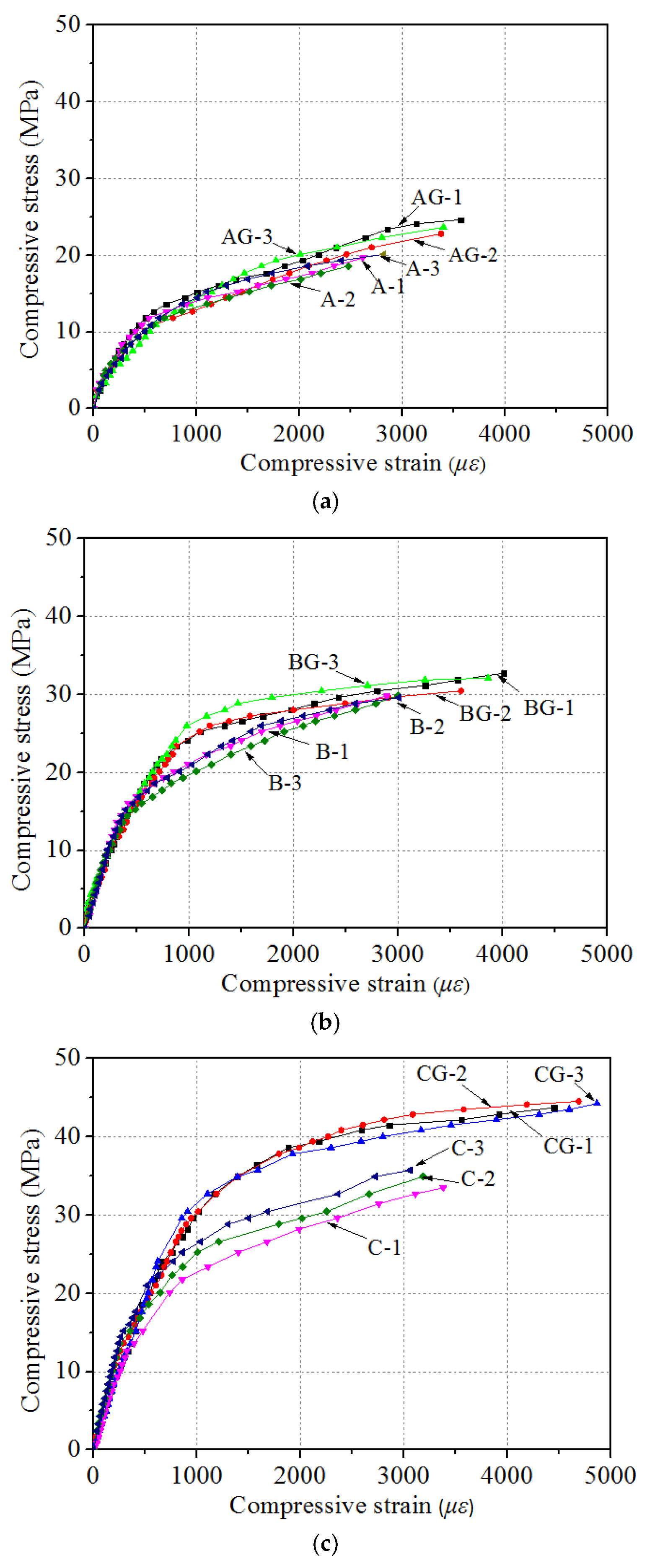
Figure 8.
Compressive stress–strain curves fitting that uses the logarithmic constitutive relation presented by Zeng et al. [33] with grouted concrete strengths of (a) 23.9 MPa; (b) 34.7 MPa; (c) 45.0 MPa.
Figure 8.
Compressive stress–strain curves fitting that uses the logarithmic constitutive relation presented by Zeng et al. [33] with grouted concrete strengths of (a) 23.9 MPa; (b) 34.7 MPa; (c) 45.0 MPa.

Figure 9.
Comparison of the experimental values (listed in Table 5) and the predicted values based on fitting.
Figure 9.
Comparison of the experimental values (listed in Table 5) and the predicted values based on fitting.

Table 1.
Properties of glass fiber-reinforced polymer (GFRP) composites.
| Nominal Thickness (mm) | Tensile Strength (MPa) | Modulus of Elasticity (GPa) | The Volume Fractions | Weight Density (g/m2) | Ultimate Elongation (%) | Fiber Direction |
|---|---|---|---|---|---|---|
| 0.436 | 660 | 83 | 29.5% | 414 | 4.3 | Uni- directional |
Table 2.
Properties of epoxy.
| Resin Type | Density (g/cm3) | Tensile Strength (MPa) | Tensile Modulus (GPa) | Thermal Expansion Coefficient (10−6/°C) | Solidification Shrinkage (%) |
|---|---|---|---|---|---|
| Epoxy | 1.2–1.3 | 35–130 | 1.75–4.1 | 40 | 1–5 |
Table 3.
Test matrix of GFRP-strengthened grouted mortarless masonry prism specimens.
| Specimen | Grouted Concrete Standard Strength (MPa) | Grouted Concrete Tested Strength (MPa) | Strengthened |
|---|---|---|---|
| AG-1,2,3 | C20 | 23.9 | GFRP |
| A-1,2,3 | C20 | 23.9 | – |
| BG-1,2,3 | C30 | 34.7 | GFRP |
| B-1,2,3 | C30 | 34.7 | – |
| CG-1,2,3 | C45 | 45.0 | GFRP |
| C-1,2,3 | C45 | 45.0 | – |
Table 4.
Compressive experimental results of the GMM and G-GMM specimens.
| Group | Sample | Grout | (MPa) | (MPa) | (MPa) | Ncr/Nu | Failure Mode | |
|---|---|---|---|---|---|---|---|---|
| Type | fcu,m (MPa) | |||||||
| G. 1 | AG-1 | GN1 | 23.9 | 19.66 | 24.63 | 11.6 | 0.80 | Z |
| AG-2 | GN2 | 23.9 | 17.37 | 22.79 | 0.76 | X | ||
| AG-3 | GN3 | 23.9 | 18.11 | 23.64 | 0.77 | X | ||
| Average | – | 23.9 | 18.38 | 23.69 | 0.78 | — | ||
| A-1 | GN1 | 23.9 | 12.51 | 19.65 | 0.64 | Y | ||
| A-2 | GN2 | 23.9 | 12.23 | 18.08 | 0.68 | Y | ||
| A-3 | GN3 | 23.9 | 12.66 | 20.11 | 0.63 | Y | ||
| Average | – | 23.9 | 12.47 | 19.28 | 0.65 | — | ||
| G. 2 | BG-1 | GN1 | 34.7 | 19.23 | 32.71 | 14.7 | 0.59 | Z |
| BG-2 | GN2 | 34.7 | 18.87 | 30.57 | 0.62 | Y | ||
| BG-3 | GN3 | 34.7 | 19.10 | 32.09 | 0.60 | Z | ||
| Average | – | 34.7 | 19.06 | 31.79 | 0.60 | — | ||
| B-1 | GN1 | 34.7 | 16.13 | 29.81 | 0.54 | Y | ||
| B-2 | GN2 | 34.7 | 16.29 | 29.87 | 0.55 | Y | ||
| B-3 | GN3 | 34.7 | 16.05 | 29.60 | 0.54 | Y | ||
| Average | – | 34.7 | 16.15 | 29.76 | 0.54 | — | ||
| G. 3 | CG-1 | GN1 | 45.0 | 23.08 | 43.70 | 17.7 | 0.53 | X |
| CG-2 | GN2 | 45.0 | 25.24 | 44.53 | 0.57 | Z | ||
| CG-3 | GN3 | 45.0 | 23.75 | 44.24 | 0.54 | Z | ||
| Average | – | 45.0 | 24.02 | 44.16 | 0.54 | — | ||
| C-1 | GN1 | 45.0 | 14.82 | 33.41 | 0.44 | Y | ||
| C-2 | GN2 | 45.0 | 14.47 | 34.67 | 0.42 | Y | ||
| C-3 | GN3 | 45.0 | 15.21 | 35.72 | 0.43 | Y | ||
| Average | – | 45.0 | 14.83 | 34.60 | 0.43 | — | ||
Table 5.
The lateral restraint stress effective factor .
| Sample | (MPa) | (MPa) | (MPa) | / | / |
|---|---|---|---|---|---|
| AG-1 | 19.28 | 24.63 | 0.829 | 0.043 | 1.277 |
| AG-2 | 19.28 | 22.79 | 0.330 | 0.017 | 1.182 |
| AG-3 | 19.28 | 23.64 | 0.792 | 0.041 | 1.226 |
| BG-1 | 29.76 | 32.71 | 0.659 | 0.022 | 1.099 |
| BG-2 | 29.76 | 30.57 | 0.132 | 0.004 | 1.027 |
| BG-3 | 29.76 | 32.09 | 0.734 | 0.025 | 1.078 |
| CG-1 | 34.60 | 43.70 | 1.020 | 0.029 | 1.263 |
| CG-2 | 34.60 | 44.53 | 1.103 | 0.032 | 1.287 |
| CG-3 | 34.60 | 44.24 | 1.108 | 0.032 | 1.279 |
© 2017 by the authors. Licensee MDPI, Basel, Switzerland. This article is an open access article distributed under the terms and conditions of the Creative Commons Attribution (CC BY) license (http://creativecommons.org/licenses/by/4.0/).
Share and Cite
MDPI and ACS Style
Huang, L.; Gao, C.; Yan, L.; Li, X.; Ma, G.; Wang, T. Experimental and Analytical Modeling of GFRP Strengthened Grouted Mortarless Masonry Prisms. Fibers 2017, 5, 18. https://doi.org/10.3390/fib5020018
AMA Style
Huang L, Gao C, Yan L, Li X, Ma G, Wang T. Experimental and Analytical Modeling of GFRP Strengthened Grouted Mortarless Masonry Prisms. Fibers. 2017; 5(2):18. https://doi.org/10.3390/fib5020018
Chicago/Turabian StyleHuang, Liang, Chang Gao, Libo Yan, Xiaoxi Li, Gao Ma, and Tianfeng Wang. 2017. "Experimental and Analytical Modeling of GFRP Strengthened Grouted Mortarless Masonry Prisms" Fibers 5, no. 2: 18. https://doi.org/10.3390/fib5020018
Note that from the first issue of 2016, this journal uses article numbers instead of page numbers. See further details here.