Torsional Fretting Wear Properties of Thermal Oxidation-Treated Ti3SiC2 Coatings

State Key Laboratory of Digital Manufacturing Equipment and Technology, School of Mechanical Science and Engineering, Huazhong University of Science and Technology, Wuhan 430074, China
*
Author to whom correspondence should be addressed.
Coatings 2018, 8(9), 324; https://doi.org/10.3390/coatings8090324
Submission received: 1 July 2018
/
Revised: 4 September 2018
/
Accepted: 12 September 2018
/
Published: 14 September 2018
Abstract
:In this study, efforts were made to oxidize the Ti3SiC2 coating surface to improve its wear resistance by producing oxide layers and healing microcracks that initiated from the thermal sprayed process. Tribological behaviors of the thermal oxidation-treated Ti3SiC2 coatings subjected to various temperatures (200, 300, and 400 °C) and durations (1, 3, and 5 h) were investigated comparatively by fretting wear. The results showed that the thickness of the oxide layer and the average content of element O on the surface were gradually increased with increasing temperature. Lower friction coefficients were observed in coatings at 200–400 °C for 1 h. Better performance of crack-healing features was demonstrated at 400 °C, whereas fresh microcracks were formed under the fretting condition due to the fragility of oxides at the same time. The tribological behavior of thermal oxidation-treated Ti3SiC2 coatings was mainly controlled by delamination and abrasive wear. The volume losses induced by wear scars decreased with the increase in oxidation time under the oxidation treatment at 200 °C and increased with increasing oxidation time under the oxidation temperatures of 300 and 400 °C.
1. Introduction
The ternary carbide Ti3SiC2, one of the MAX phases, is of significant interest for its potential in tribological applications due to its remarkable combination of properties in damage tolerance, machinability, electric and thermal conductivity, self-healing capability, and lubrication [1,2,3,4,5,6,7]. However, the conditions allowing excellent tribological properties are limited to either high sliding speed or high temperature, which cause the formation of tribo-induced oxides on the contact interfaces [8,9,10,11,12,13,14,15]. The synthesized Ti3SiC2 bulks restrict the potential for tribological applications in engineering components, whereas plasma spraying with a high spray temperature and a prominent deposition rate provides an efficient way to achieve these wear-resistant coatings of the MAX phase. The plasma-sprayed Ti3SiC2 coatings exhibited improved fretting wear properties because of the healed cracks by selective oxidation of Ti3SiC2 and the lubrication of tribo-induced oxides [16]. However, the friction coefficient maintained at a relatively higher level compared with that in high temperature or high sliding speed.
It has been observed that the lubricious oxide layer on the frictional surface of Ti3SiC2 was composed of amorphous titanium and silicon oxides [17]. Similar oxidation could occur in thermal-treated Ti3SiC2 coating surfaces. The oxidation process was controlled by the inward diffusion of oxygen and the outward diffusion of titanium, resulting in a stratified structure of an outer rutile and an inner rutile/silica layer [18,19,20]. Lubricious rutile with tribo-oxidation or pre-oxidation treatment has been proved to be effective in reducing the friction and wear of Ti-based alloys [21,22] as well as Ti3SiC2 [23]. In addition, it has been demonstrated that crack damage in MAX phase, which could be easily observed in thermal-sprayed coatings [24,25], could be healed by filling the crack gap with well-adhering oxides and other reaction products to restore the material integrity [26,27,28,29,30]. Thus, it is valuable to explore the fretting wear behavior of Ti3SiC2 coatings with oxidation treatment for a further improvement of their tribological properties.
For this paper, plasma-sprayed Ti3SiC2 coatings were thermal oxidation-treated at 200, 300, and 400 °C for various durations to improve the fretting wear properties. Previous research on the oxidation behavior of Ti3SiC2 has been conducted at temperatures above 900 °C [31,32] and at intermediate temperatures from 500 to 900 °C [33]. However, considering the operating temperature of the coating substrates (CuNiAl), the maximum temperature in this research was limited within 400 °C. The morphologies of oxidized Ti3SiC2 were investigated by X-ray diffraction (XRD) and an energy-dispersive X-ray spectroscopy (EDS) analyzer. The tribological behaviors of oxidized Ti3SiC2 against 42CrMo4 were comparatively studied under a flat-on-flat contact. Furthermore, the oxidation of Ti3SiC2 as well as the wear mechanism under different conditions were analyzed, and are discussed below in detail.
2. Materials and Experimental Methodology
2.1. Materials and Thermal Oxidation of Ti3SiC2 Coatings
The Ti3SiC2 coatings were deposited by an air plasma spray (APS) system on grit-blasted (3 bar, corundum EKF 30) nickel-aluminum bronze substrates with a dimension of 30 × 50 × 7 mm3. Commercial grade Ti3SiC2 powders (purity ≥ 98.0 wt %) with a particle size of 40 μm served as starting materials and details of the components have been reported in our recent work [16]. The plasma spray parameters were listed as follows: the input power supplied to the gun was 33 kW, the primary gas (Ar) flow rate was 33 standard liters per minute (slpm), the secondary gas (H2) flow rate was 2 slpm, and the spray distance was 85 mm.
Thermal oxidation of Ti3SiC2 coatings was carried out in an air furnace at various temperatures ranging from 200 to 400 °C for a period of 1–5 h. The rate of heating process was about 2 °C/min and the specimen was laid in the furnace to cool itself after oxidation treatment. All the specimens were grounded, polished, and degreased in ethanol before experiments.
2.2. Torsional Fretting Test
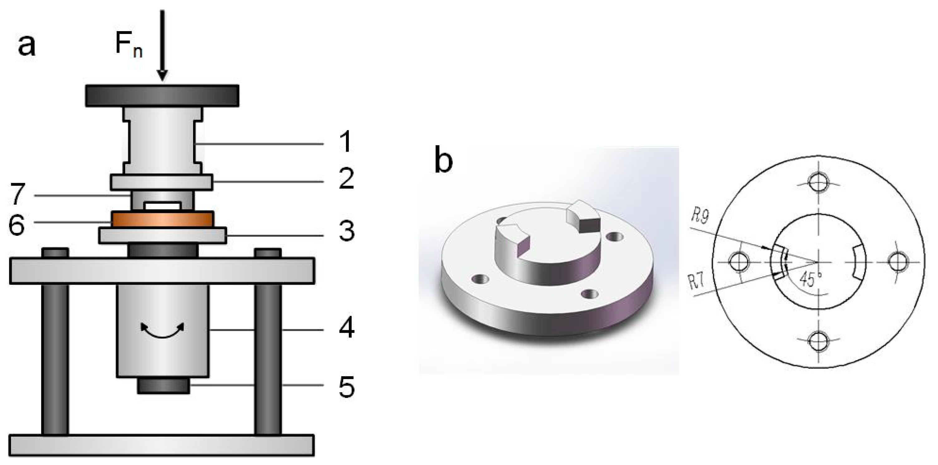
Torsional fretting wear tests were performed on a self-built torsional fretting tester with a flat-on-flat contact configuration as shown in Figure 1a. The test rig has been described in detail in previous studies of our lab [34,35,36]. Briefly, the normal loads (Fn) were applied by dead weights from the top. The angular displacement amplitude (θ), the frequency, and the total fretting cycles were controlled by the motor impulse and measured by an encoder. The lower flat specimen was fixed on the lower holder, which was driven by a reduced speed stepping motor (57PG1441-010, Shenzhen Meilake Technology Co., Ltd., Shenzhen, China). The upper counter-body (42CrMo4, Figure 1b) was designed in a partial annulus with two raised 45° sectors and fixed on the upper holder, which was connected to a torque sensor [37,38].
The test parameters were set as follows: the angular displacement amplitude (θ) was 1.5° and the normal load (Fn) was 106 N. The frequency was 2 Hz and the total number of cycles was 40,000. All tests were carried out at 23 °C in laboratory ambient conditions with a relative humidity of 40%–45%, and all specimens were cleaned with ethanol and dried with cold air after tests. The experiment was repeated twice.
2.3. Analysis
The phase compositions of oxidized Ti3SiC2 coatings were identified by X-ray diffraction (XRD) (X’Pert Pro/Empyrean, PANalytical B.V., Almelo, The Netherlands) with Cu-Kα radiation. The surface morphologies and the wear volume were measured by a three-dimensional (3D) optical microscope (DSX510, OLYMPUS, Tokyo, Japan). The morphologies of worn surfaces as well as initial surfaces and cross-sections of the oxidized samples were conducted using a field emission scanning electron microscope (FESEM) (Helios G3 CX, FEI Czech Republic Ltd., Brno, Czech Republic) equipped with an energy-dispersive X-ray spectroscopy (EDS) analyzer.
3. Experimental Results and Discussion
3.1. Composition and Characterization of Thermal Oxidation-Treated Coatings
The XRD patterns of the oxide scales on the Ti3SiC2 coatings after the thermal-oxidation treatment at 200–400 °C for 1 h are exhibited in Figure 2, using the XRD patterns of as-sprayed Ti3SiC2 coatings as a contrast, and only 2θ with the range of 22°–42° is shown for clarity. The XRD results of samples for 3–5 h were similar to those shown in Figure 2, so the results of coatings with 1 h treatment were chosen to show the differences at various temperatures. No diffraction peaks of any oxides were detected at the oxidation temperature of 200 °C. With increasing temperatures, both anatase TiO2 and rutile TiO2 were identified at 300–400 °C, and still no peaks of oxides of Si were found in the XRD pattern. The intensity of the diffraction peaks associated with rutile TiO2 was more significant at 400 °C than that of anatase TiO2. Furthermore, it should be noted that the intensity of Ti3SiC2 peaks exhibited an evident decrease after thermal-oxidation treatment corresponding to the variation of the intensity of TiC peaks. This implied that the oxide scales formed during oxidation were transformed mostly by the oxidation reaction of the Ti3SiC2 phases.
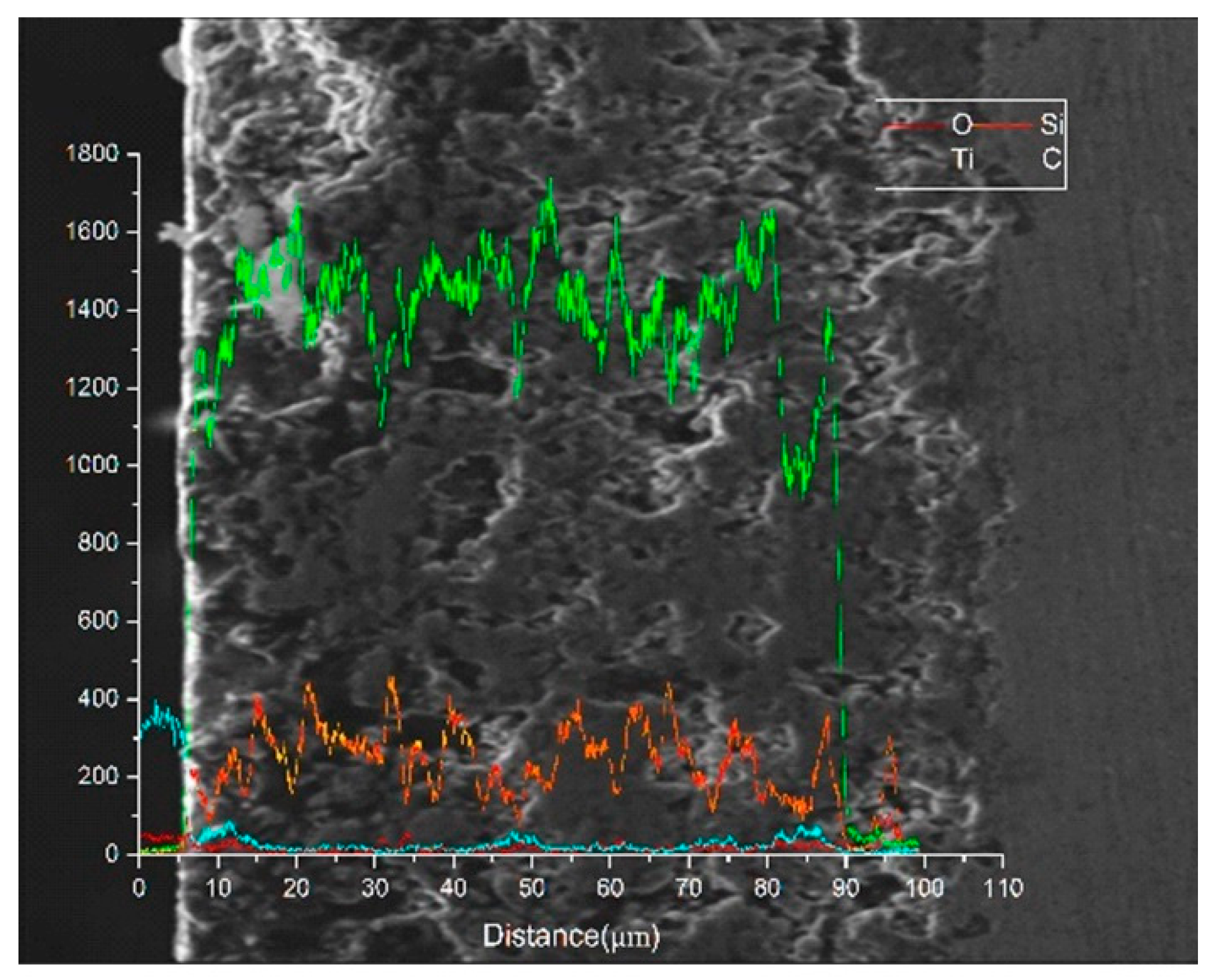
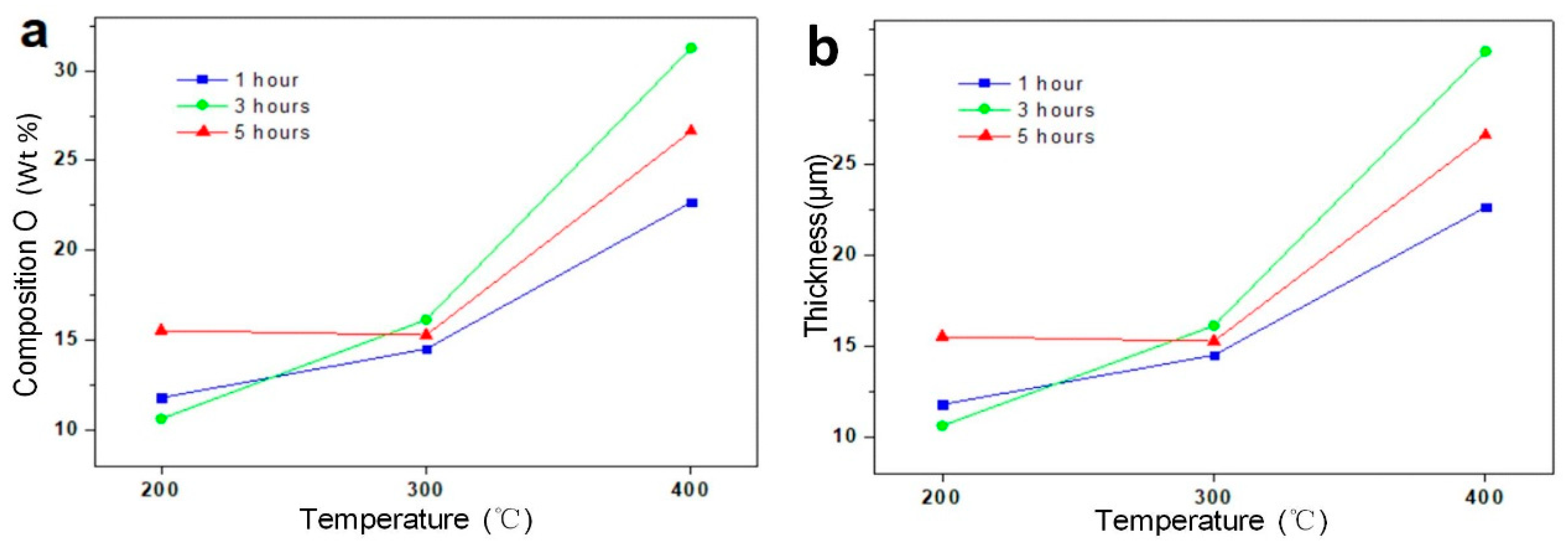
The chemical compositions of the initial surface and the cross-section taken from the sample oxidized at 200 °C for 1 h were measured by the EDS elemental scans of Ti, Cu, Si, C, and O, as shown in Figure 3. It can be observed that the oxide should be a mixture of titanium oxide and silicon oxide. The sample oxidized at 400 °C for 1 h also had a mixture of titanium oxide and silicon oxide, as shown in Figure 4a. This agrees with the results of previous publications [23,33]. The contents of oxides as well as the thickness of the oxide layers were estimated according to a cross-section EDS analysis. The thickness value is defined as the mean value of the maximum and the minimum values, as shown in Figure 4b. The maximum and minimum values refer to the depths to which the intensity of element O and Ti gradually reached for the average value of coatings. The measurements of oxidation at 200–400 °C for 1–5 h were observed in the same manner. Figure 5a shows the average composition of element O on the surface, and Figure 5b shows the thickness of the oxide layer as a function of oxidation temperature. The peaks of element O were justified under the oxidation temperature of 200 °C in Figure 4a, whereas the thickness of the oxide layers was maintained at a relatively limited value in Figure 4b. In addition, it can be seen that for both the curves, the average composition as well as the thickness increased with increasing temperature but remained at a similar value under various oxidation times. From the macro view, the oxidation is mainly a function of oxidation temperature.
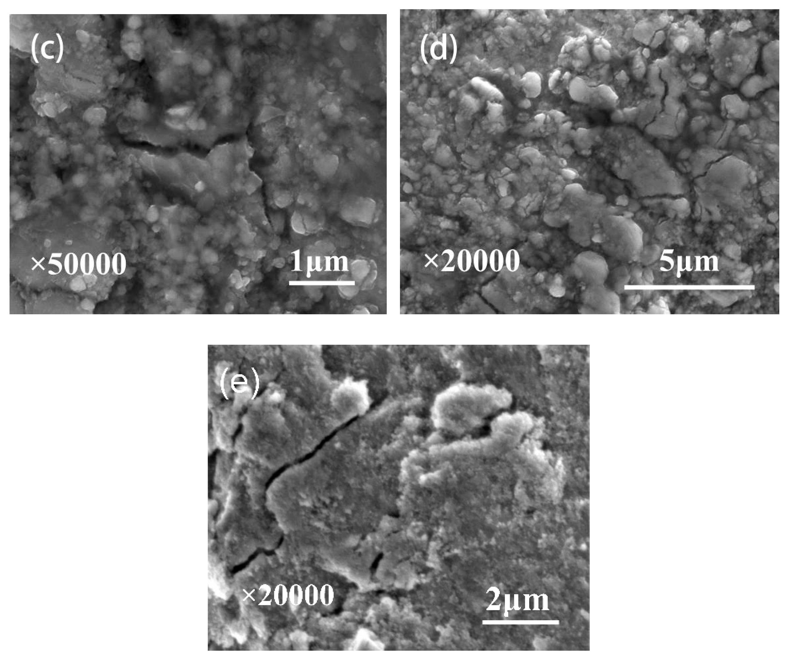
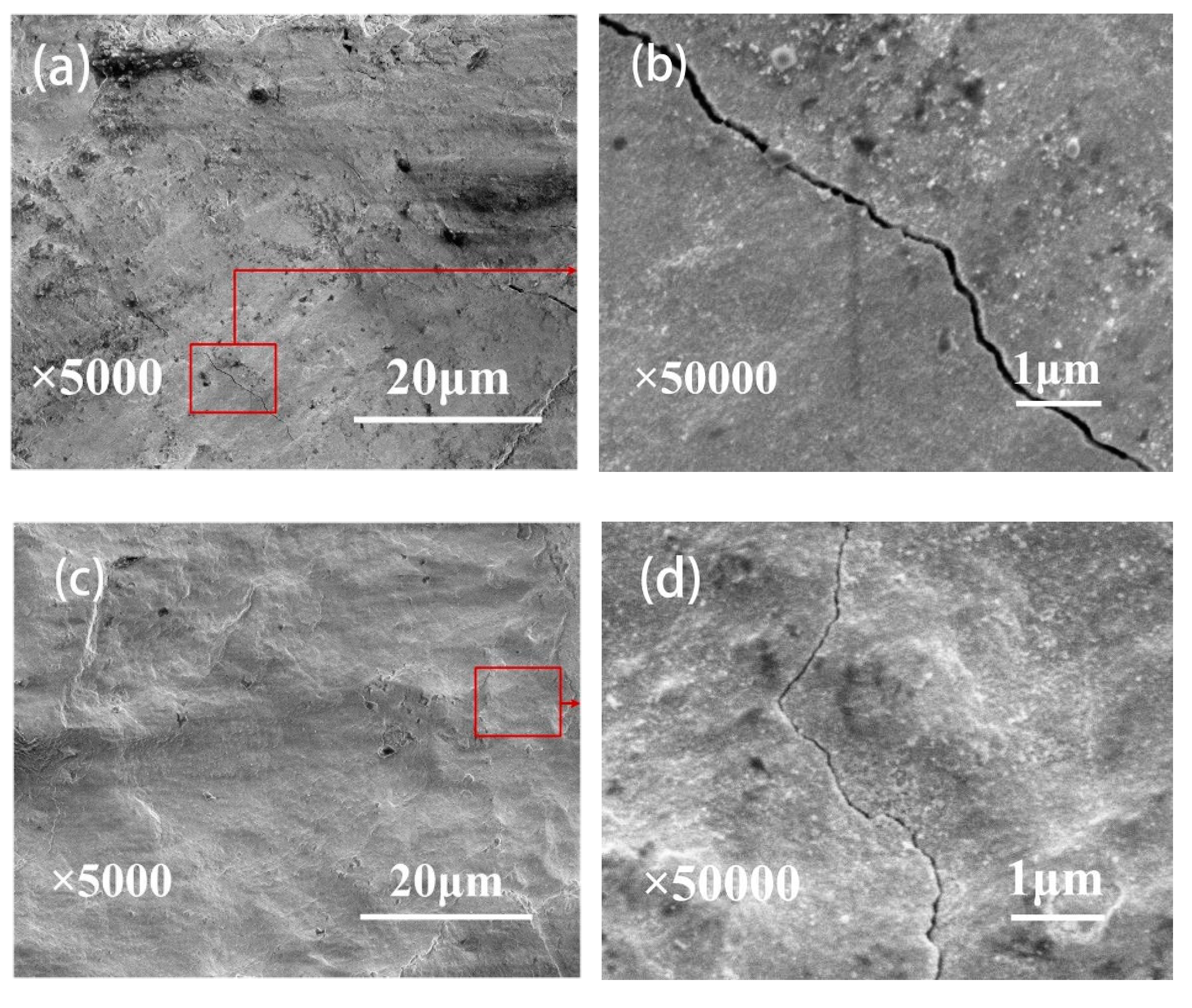
The typical morphologies of microcracks in Ti3SiC2 specimens before the thermal treatment and after the oxidation treatment at 200–400 °C are shown in Figure 6. The cracks in the Ti3SiC2 coatings, which were easily formed during the plasma spraying process [24,25], as seen in Figure 6e, were quite distinct after the oxidation treatment at 200 °C (Figure 6a). On the other hand, the cracks after the oxidation treatment at 300 °C (Figure 6b) were partially filled with oxides due to the self-healing capability of Ti3SiC2 phases. The well-adhering phases of TiO2 and some other productions formed by the selective oxidation of Ti3SiC2 are even more significant in the crack gap at a higher temperature of 400 °C (Figure 6c). Meanwhile, the microcracks that occurred in the oxide layers during the oxidation treatment at 400 °C (Figure 6d) were still partially filled with oxides. The formation of microcracks was presumably caused by the stress produced by a phase change in the oxide products [33]. The results support the conclusion that both the oxidation temperature and time have an influence on the microcracks.
3.2. Friction Kinetics Behavior
The fretting running kinetics behaviors can be described by the friction torque vs. angular displacement amplitude loops (T-θ curves) [39,40,41]. As shown in Figure 7, the T-θ curves of all cycles under the oxidation temperature of 400 °C show the parallelogram shape. Similarly, the torsional fretting wear under various temperatures should be running in the gross slip regime of fretting maps. A more detailed discussion follows about the effect of oxidation treatment on the fretting running behaviors. The friction coefficient is depicted as a function of the number of cycles with logarithmic coordinates as shown in Figure 8, calculated by using the average amplitude Ti of a T-θ curve of each fretting cycle [42,43]. Generally, there are three typical stages that occur in the fretting running progress [44,45,46]. In the initial stage (stage I), the friction coefficients are relatively small, which could be due to two reasons: first, because of the protection and lubrication of fresh films on contacting surfaces; and second, because of the relative high roughness at very beginning of contact that causes a higher contact pressure, resulting in low friction [47,48]. After approximately 10 or 100 cycles, the curves increase quickly and enter the ascent stage (stage II), due to the adhesion and abrasion between the contact interfaces that are more flattened with the bigger contact area. Then, the curves achieve a steady value in the steady stage (stage III), corresponding to the fluctuation within a narrow range. In addition, the friction coefficients show a relationship with the oxidation temperature and time. Because of the lubrication of titanium oxide formed during oxidation treatment and at the oxidation temperature of 200 °C, as seen in Figure 8a, the friction coefficient values of coatings in the steady stage showed a relatively lower level with the oxidation time of 1 and 3 h compared to those without oxidation treatment. Because of the adhesion of oxides and some contaminants on the surface, the surface damage was lighter and the friction coefficients up to 100 cycles were the same for all samples tested for 1 to 5 h, as seen in Figure 8b, whereas the friction coefficient rose with the longer oxidation time of 5 h. Because of the destruction of the surface layers on the surface, the initial friction coefficient of different samples remained almost the same. The oxide layer introduced by different oxidation pretreatments had different effects mainly on the fretting wear process, resulting in different friction coefficients at the stabilization stage. Moreover, when the oxidation temperature increased to 300 °C (Figure 8b) or 400 °C (Figure 8c), with 1 h oxidation, the friction coefficient at the steady stage maintained a significantly lower value. As the oxidation time increased, the roughness of the coating surface increased, as seen in Figure 8d. Therefore, the increase in oxidation time corresponded to an elevated value in the steady stage of the friction coefficient. This suggests that the friction coefficient will have a relatively lower value with decreased oxidation time. The 1 h oxidation treatment is expected to have a better lubrication effect.
3.3. Wear Scar Observation
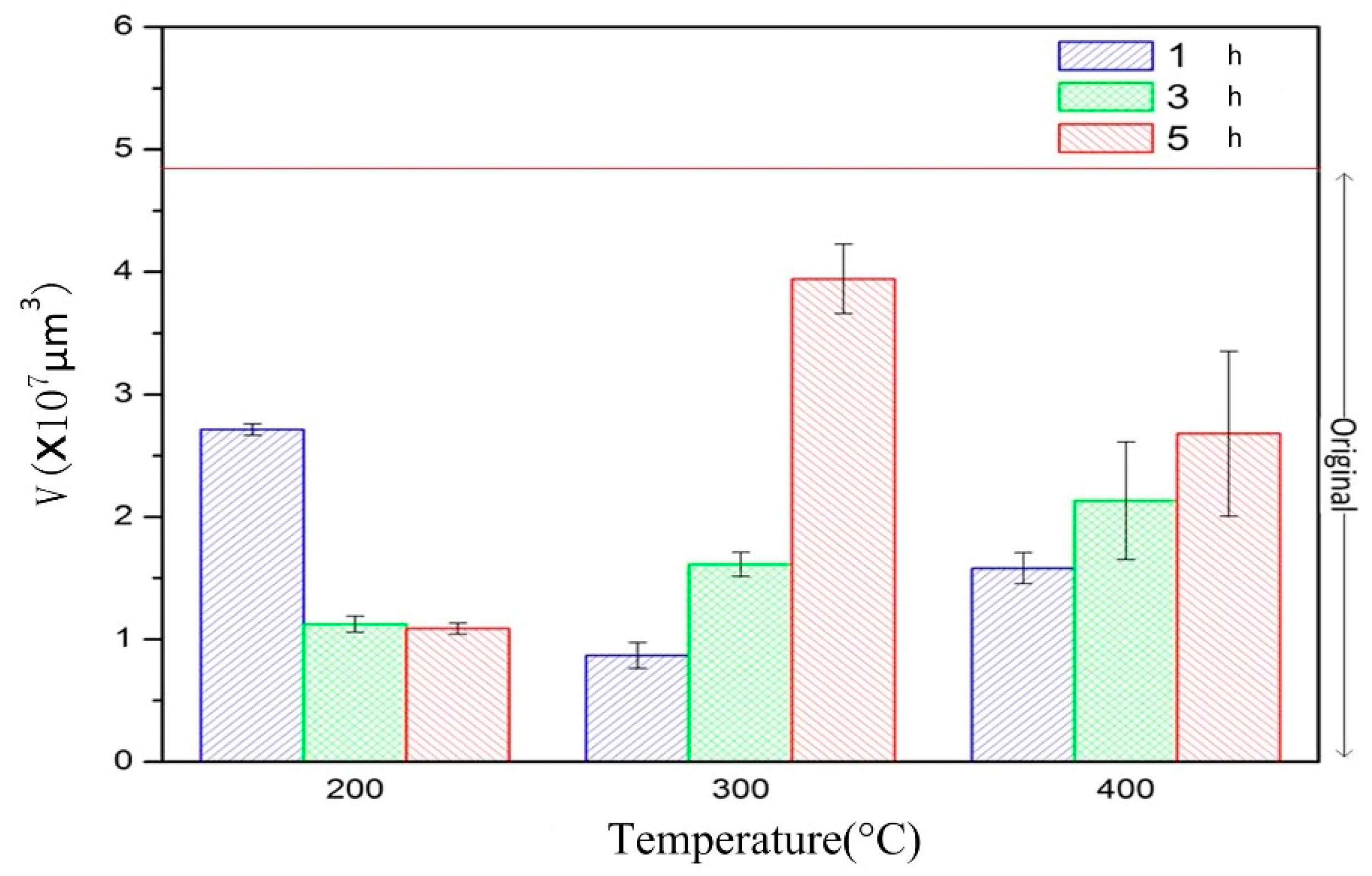
Detailed analyses of wear scars were carried out by measuring the wear volume with a 3D optical microscope and typical morphologies with a scanning electron microscope (SEM). As shown in Figure 9, the wear volume of oxidation-treated Ti3SiC2 coatings was compared to evaluate the wear resistance of those coatings with different oxidation temperatures and durations. It was noted that all the wear volumes exhibited an appreciable decrease after oxidation treatment under fretting wear, due to the lubrication of TiO2 and the healing of microcracks formed by the oxidizing reaction of Ti3SiC2 coatings during oxidation treatment. Furthermore, the volume losses of coatings under the oxidation treatment at 200 °C decreased with the increase in oxidation time. As mentioned previously, the thickness of oxide layers as well as the content of element O were quite low under the oxidation temperature of 200 °C. The healing performance of microcracks still could not be identified at 200 °C. The increasing oxidation time provided more titanium oxide to form a protective and lubricated layer on the contact interfaces. With the increasing temperature, the oxidation was conspicuous at 300 and 400 °C (as shown in Figure 5), whereas the friction coefficients tended to increase with increasing oxidation time. The wear volume under the oxidation temperature of 300 and 400 °C showed an increasing tendency with increasing oxidation time. Moreover, the crack was partially filled at 300 °C, whereas the crack-healing feature was more pronounced at 400 °C. The highest volume loss was observed at coatings under the oxidation temperature of 300 °C and the oxidation time of 5 h. Despite better original crack healing at 400 °C, the initial surface caused more cracks due to the oxide formation process and the brittleness of the oxide during wear. The lowest volume loss occurred under the oxidation temperature of 300 °C and the oxidation time of 1 h.
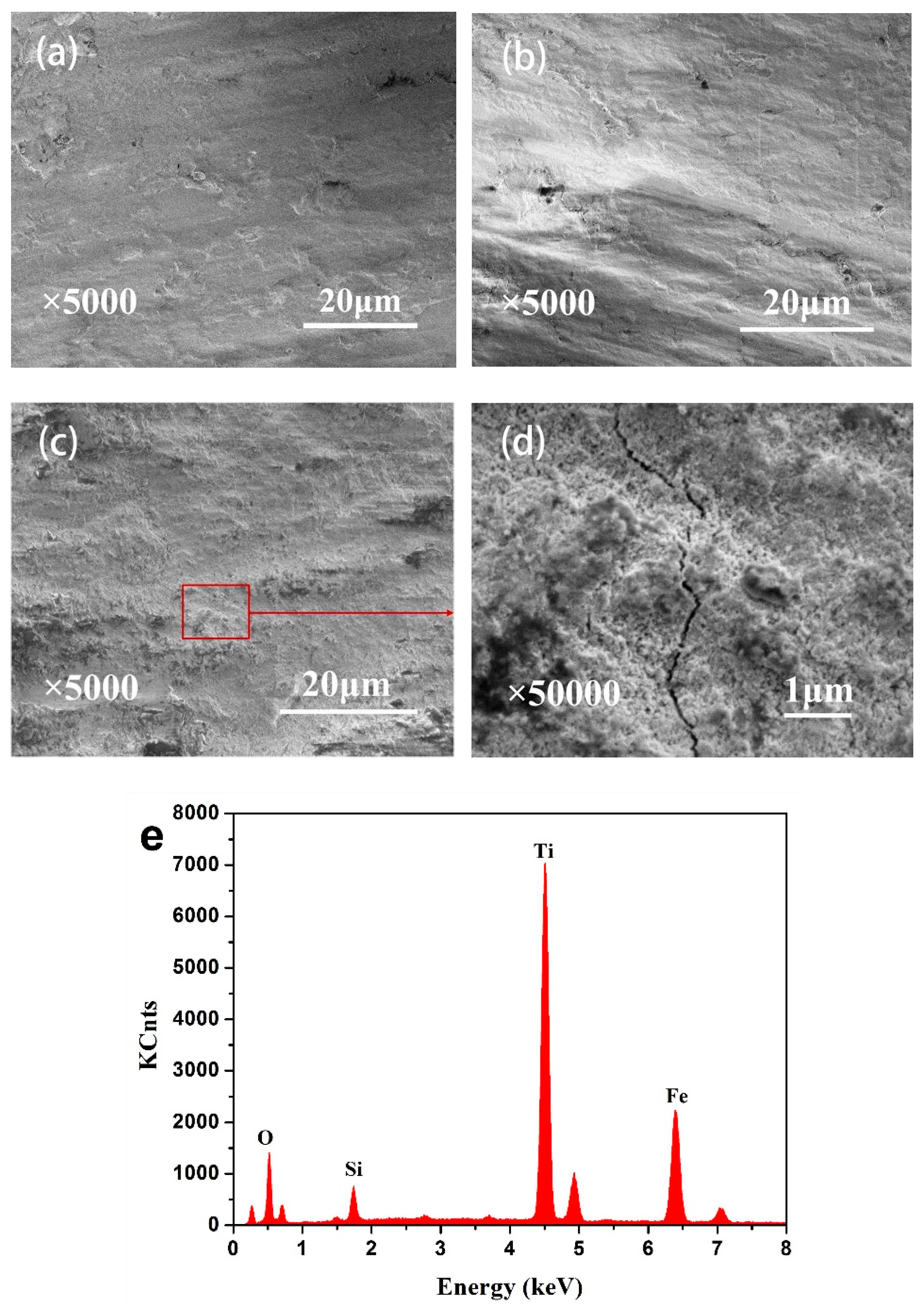
Typical SEM morphologies of wear scars under various oxidation treatments of 200 °C are presented in Figure 10, respectively. As shown in Figure 10a,b, coatings after the oxidation treatment of 1 and 3 h were mainly controlled by wear mechanisms of delamination and abrasive wear. With the increase in oxidation time to 5 h, the main wear mechanisms were still delamination and abrasive wear, but visible deformation (Figure 10c) and cracks under a higher magnification in Figure 10d were observed at the same time. Furthermore, the oxide layers were justified by the EDS patterns shown in Figure 10e. These results, combined with those in our previous study [16], showed that the oxide layers formed by the fretting wear process were composed of TiO2, SiO2, Fe2O3, and Fe3O4 debris transferred from the counterpart. It was noted that the composition of element O was significantly increased due to the pre-oxidation treatment and the transformation from the counterfaces. The generated oxide layers acted as a lubrication function and prevented the wear surface from severe damage, corresponding to the decreasing friction coefficient and volume losses compared to the Ti3SiC2 coatings without oxidation treatment. All the specimens were cleaned with ethanol in an ultrasonic bath and the loose debris was cleared; the remaining debris should not be considered as a source of error, but rather as an effect of various testing conditions [49]. The oxide layers on the worn surface of 200 °C and 5 h (Figure 10c) were rougher than that with the oxidation time of 1 and 3 h (Figure 10a,b), due to the deformation during fretting wear. That occurred considering the fact of the increasing friction coefficient, as shown in Figure 8a.
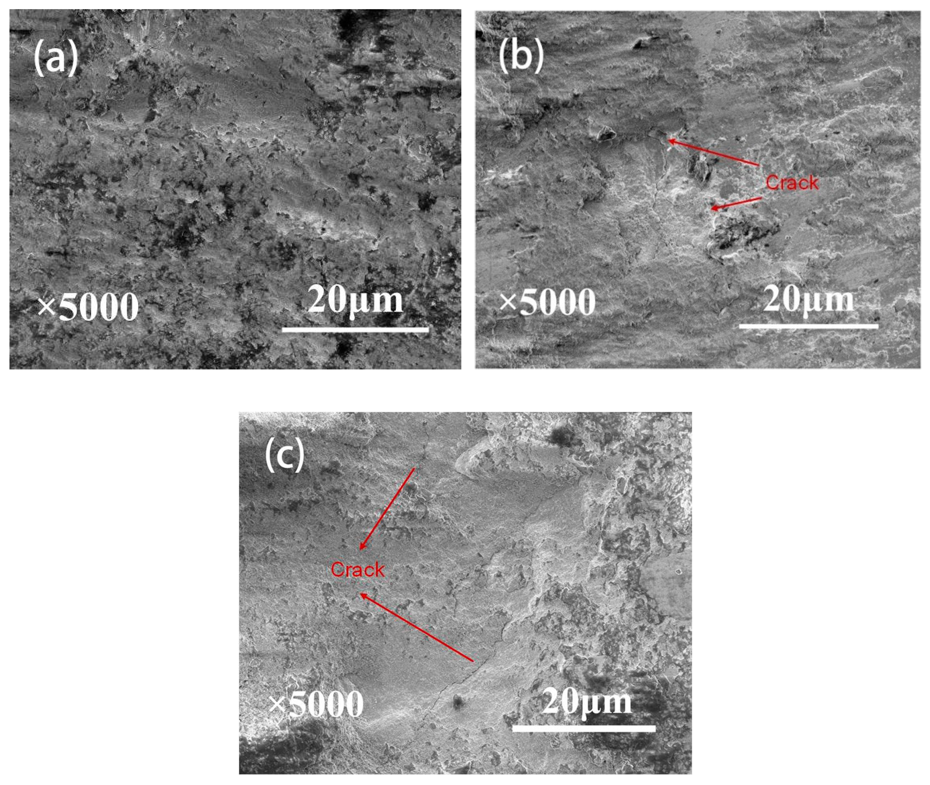
Figure 11 presents the SEM worn surface morphologies of oxidation-treated Ti3SiC2 coatings at 300 °C. There was only slight damage with the oxidation treatment of 1 h, as shown in Figure 11a, caused by the delamination and abrasive wear. Deformation was revealed under the oxidation time of 3 and 5 h in Figure 11b,c, with an increasing friction coefficient (Figure 8b). The cracks on the wear scars were distinct even in the morphology with a low magnification, as shown in Figure 11b,c. These cracks were mainly caused by reciprocating loading and unloading during the fretting wear procedure. On the one hand, the increase in oxidation temperature was associated with the microcracks that were only partially filled in the original coating surfaces (Figure 6b). On the other hand, it resulted in the increase in thickness of the oxide layers (Figure 5b), accompanied by the brittle oxide which was highly susceptible to cracks under fretting. The cracks propagated and were encountered on the worn surface, refined between the contact interfaces, and then led to further abrasive wear. In this case, the damage to the worn surface was quite severe with the oxidation temperature of 3 and 5 h.
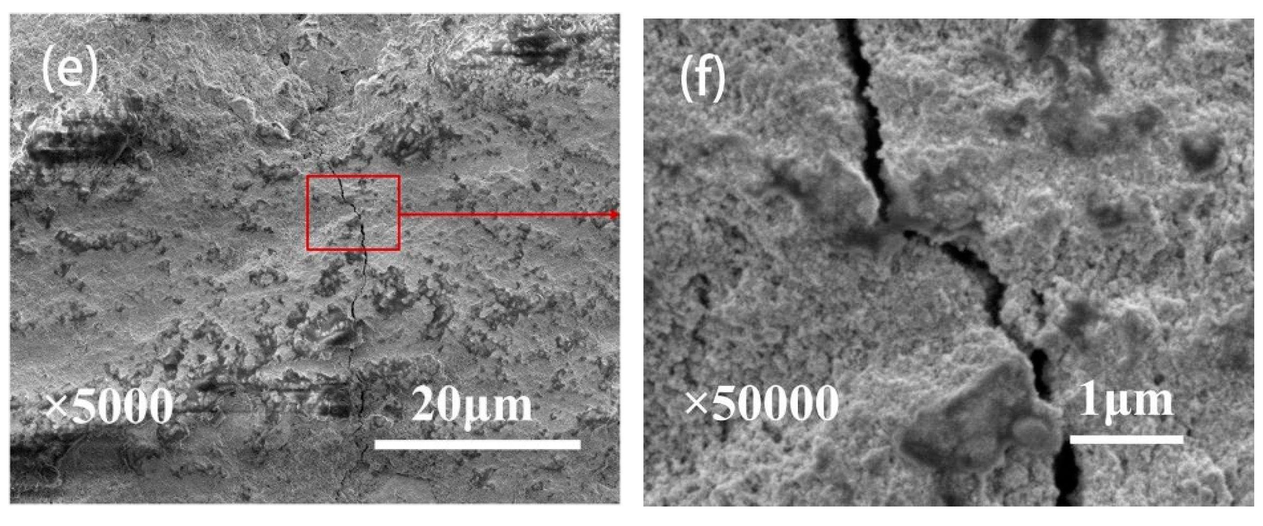
With the oxidation temperature of 400 °C, SEM micrographs of wear scars under various oxidation times are shown in Figure 12. It was seen from the morphologies in Figure 12a,c,e that the wear damage was still formed by delamination and abrasive wear and cracks were easily found on the wear surface, as shown in Figure 12b,d,f. The fretting wear ran in the same mechanism as the one presented in Figure 11c. Similarly, the increasing temperatures of oxidation treatment further increased the thickness of the oxide layers (Figure 5c). However, the microcracks on the coating surface were completely healed by the oxides filled in the crack gap (Figure 6c). The overall effect was determined by both, and the propagation of cracks on the original coating surface could be markedly inhibited by the healing process, resulting in the reduced volume losses at 3 and 5 h under the oxidation temperature of 400 °C. In addition, the increasing composition of element O on the surface could lead to a decrease in the friction coefficient (Figure 8c), compared to that at 300 °C, although the wear scars were both rough in the morphologies.
4. Conclusions
Torsional fretting wear tests of oxidation-treated Ti3SiC2 coatings under various temperatures and durations were investigated with a flat-on-flat contact configuration. The oxidative behaviors, the fretting running behaviors, the wear mechanism as well as the effect of various oxidation temperatures and times are discussed comparatively. The main conclusions obtained from this study are as follows:
- A combination of XRD and EDS patterns demonstrated that the products formed during oxidation treatment consisted mainly of TiO2, which was transformed mostly by the oxidation reaction of Ti3SiC2 phases. The average composition of element O as well as the thickness of oxide layers increased with increasing temperature. Well-adhering phases of TiO2 and some other productions healed the original cracks on the plasma-sprayed coatings with the increased oxidation temperature of 400 °C.
- According to the T-θ curves and damage morphologies, the torsional fretting was expected to run in the gross slip regime, and the main wear mechanisms were delamination and abrasive wear.
- The friction coefficient was expected to have a relatively lower value with decreased oxidation time. The morphologies of wear scars with increased oxidation time were rougher due to the deformation in the fretting wear process.
- Compared with the as-deposited Ti3SiC2 coatings, the wear volume exhibited an appreciable decrease after oxidation treatment due to the lubrication of TiO2 and the healing of microcracks generated by the oxidizing reaction of Ti3SiC2. The wear volume of coatings showed a decrease with the increase in oxidation time under the oxidation treatment at 200 °C, whereas there was an increase with increasing oxidation time under the oxidation temperature of 300 and 400 °C. Despite better original crack healing at 400 °C, the higher number of cracks was caused on the initial surface due to the oxide formation process and the brittleness of the oxide during wear. The preferable tribological performances were obtained under the oxidation temperature of 300 °C and the oxidation time of 1 h.
Author Contributions
Conceptualization, J.W. and Y.S.; Methodology, J.W. and Y.S.; Investigation, J.W., Y.S. and X.L.; Formal Analysis, J.W. and X.L.; Writing—Original Draft Preparation, J.W.; Writing—Review & Editing, Y.S.; Funding Acquisition, Y.S.
Funding
This research was funded by National Basic Research Program of China (No. 2014CB046705) and the National Natural Science Foundation of China (No. 51705178).
Conflicts of Interest
The authors declare no conflict of interest.
References
- Barsoum, M.W. The Mn+1AXn phases: A new class of solids: Thermodynamically stable nanolaminates. Prog. Solid State Chem. 2000, 28, 201–281. [Google Scholar] [CrossRef]
- Zhan, X.; Li, Z.; Gao, Z.; Zheng, L.; Wang, X.; Wang, J.; Zhou, Y. Strengthening Ti3AlC2 by in situ synthesizing Ti3AlC2-Y4Al2O9 composites. J. Am. Ceram. Soc. 2012, 95, 2314–2321. [Google Scholar] [CrossRef]
- Zhang, H.; Wang, X.; Wan, P.; Zhan, X.; Zhou, Y. Insights into high-temperature uniaxial compression deformation behavior of Ti3AlC2. J. Am. Ceram. Soc. 2015, 98, 3332–3337. [Google Scholar] [CrossRef]
- Myhra, S.; Summers, J.W.B.; Kisi, E.H. Ti3SiC2—A layered ceramic exhibiting ultra-low friction. Mater. Lett. 1999, 39, 6–11. [Google Scholar] [CrossRef]
- Zhai, W.; Lu, W.; Zhang, P.; Wang, J.; Liu, X.; Zhou, L. Wear-triggered self-healing nanocrystalline nickel aluminum bronze/Ti3SiC2. Appl. Surf. Sci. 2018, 436, 1038–1049. [Google Scholar] [CrossRef]
- Shao, Z.; Sun, Y.; Liu, W.; Zhang, X.; Jiang, X. Effects of multi-phase reinforcements on microstructures, mechanical and tribological properties of Cu/Ti3SiC2/C/BN/GNPs nanocomposites sintered by vacuum hot-pressing and hot isostatic pressing. Metals 2016, 6, 324. [Google Scholar] [CrossRef]
- Chen, X.; Bei, G. Toughening mechanisms in nanolayered MAX phase ceramics—A review. Materials 2017, 10, 366. [Google Scholar] [CrossRef] [PubMed]
- Ren, S.; Meng, J.; Lu, J.; Yang, S. Tribological behavior of Ti3SiC2 sliding against Ni-based alloys at alevated temperatures. Tribol. Lett. 2008, 31, 129–137. [Google Scholar] [CrossRef]
- Zhang, P.; Lu, W.; Liu, X.; Zhai, W.; Zhou, M.; Zeng, W. Torsional fretting and torsional sliding wear behaviors of CuNiAl against 42CrMo4 under dry condition. Tribol. Int. 2018, 118, 11–19. [Google Scholar] [CrossRef]
- Shi, W.; Luo, X.; Zhang, Z.; Liu, Y.; Lu, W. Influence of external load on the frictional characteristics of rotary model using a molecular dynamics approach. Comput. Mater. Sci. 2016, 122, 201–209. [Google Scholar] [CrossRef]
- Lu, W.; Zhang, G.; Liu, X.; Zhou, L.; Chen, L.; Jiang, X. Prediction of surface topography at the end of sliding running-in wear based on areal surface parameters. Tribol. Trans. 2014, 57, 553–560. [Google Scholar] [CrossRef]
- Zhang, G.; Liu, X.; Lu, W. A parameter prediction model of runing-in based on surface topography. Proc. Inst. Mech. Eng. Part J J. Eng. Tribol. 2013, 227, 1047–1055. [Google Scholar] [CrossRef]
- Hai, W.; Ren, S.; Meng, J.; Lu, J. Tribo-oxidation of self-mated Ti3SiC2 at elevated temperatures and low speed. Tribol. Lett. 2012, 48, 425–432. [Google Scholar] [CrossRef]
- Zhai, W.; Shi, X.; Yang, K.; Huang, Y.; Zhou, L.; Lu, W. Mechanical and tribological behaviors of the tribo-layer of the nano crystalline sturcture during sliding contact: Experiments and model assessment. Compos. Part B Eng. 2017, 108, 354–363. [Google Scholar] [CrossRef]
- Zhang, R.; Feng, K.; Meng, J.; Liu, F.; Ren, S.; Hai, W.; Zhang, A. Tribological behavior of Ti3SiC2 and Ti3SiC2/Pb composites sliding against Ni-based alloys at elevated temperatures. Cerim. Int. 2016, 42, 7107–7117. [Google Scholar] [CrossRef]
- Zhou, M.; Lu, W.; Liu, X.; Zhai, W.; Zhang, P.; Zhang, G. Fretting wear properties of plasma-sprayed Ti3SiC2 coatings with oxidative crack-healing feature. Tribol. Int. 2017, 118, 196–207. [Google Scholar] [CrossRef]
- Zhai, H.; Huang, Z.; Zhou, Y.; Zhang, Z.; Wang, Y.; Ai, M. Oxidation layer in sliding friction surface of high-purity Ti3SiC2. J. Mater. Sci. 2004, 39, 6635–6637. [Google Scholar] [CrossRef]
- Barsoum, M.W.; El-Raghy, T. Oxidation of Ti3SiC2 in air. J. Electrochem. Soc. 1997, 144, 2508–2516. [Google Scholar] [CrossRef]
- Sun, Z.; Zhou, Y.; Li, M. Cyclic-Oxidation behavior of Ti3SiC2-base material at 1100 °C. Oxidation Met. 2002, 57, 379–394. [Google Scholar] [CrossRef]
- Lee, D.B.; Park, S.W. Oxidation of Ti3SiC2 between 900 and 1200 °C in air. Oxid. Met. 2007, 67, 51–66. [Google Scholar] [CrossRef]
- Król, S.; Ptacek, L.; Zalisz, Z.; Hepner, M. Friction and wear properties of titanium and oxidised titanium in dry sliding against hardened C45 steel. J. Mater. Process. Technol. 2004, 157–158, 364–369. [Google Scholar] [CrossRef]
- Krishna, D.S.R.; Brama, Y.L.; Sun, Y. Thick rutile layer on titanium for tribological applications. Tribol. Int. 2007, 40, 329–334. [Google Scholar]
- Ren, S.; Meng, J.; Wang, J.; Lu, J.; Yang, S. Friction and wear of thermal oxidation-treated Ti3SiC2. Tribol. Lett. 2010, 37, 59–67. [Google Scholar] [CrossRef]
- Basu, S.N.; Ye, G.; Gevelber, M.; Wroblewski, D. Microcrack formation in plasma sprayed thermal barrier coatings. Int. J. Refract. Met. Hard Mater. 2005, 23, 335–343. [Google Scholar] [CrossRef]
- Yang, Z.C.; Zhong, Y.C.; Zhou, C.S. Quantitative assessment of the surface crack density in thermal barrier coatings. Acta Mech. Sin. 2014, 30, 167–174. [Google Scholar] [CrossRef]
- Song, G.M.; Pei, Y.T.; Sloof, W.G.; Li, S.B.; De Hosson, J.T.M.; Van der Zwaag, S. Oxidation-induced crack healing in Ti3AlC2 ceramics. Scr. Mater. 2008, 58, 13–16. [Google Scholar] [CrossRef]
- Farle, A.S.; Kwakernaak, C.; van der Zwaag, S.; Sloof, W.G. A conceptual study into the potential of Mn+1AXn-phase ceramics for self-healing of crack damage. J. Eur. Ceram. Soc. 2015, 35, 37–45. [Google Scholar] [CrossRef]
- Pei, R.; McDonald, S.A.; Shen, L.; van der Zwaag, S.; Sloof, W.G.; Withers, P.J.; Mummery, P.M. Crack healing behaviour of Cr2AlC MAX phase studied by X-ray tomography. J. Eur. Ceram. Soc. 2017, 37, 441–450. [Google Scholar] [CrossRef]
- Li, S.; Xiao, L.; Song, G.; Wu, X.; Sloof, W.G.; van der Zwaag, S. Oxidation and crack healing behavior of a fine-grained Cr2AlC ceramic. J. Am. Ceram. Soc. 2013, 96, 892–899. [Google Scholar] [CrossRef]
- Shen, L.; Eichner, D.; van der Zwaag, S.; Leyens, C.; Sloof, W.G. Reducing the erosive wear rate of Cr2AlC MAX phase ceramic by oxidative healing of local impact damage. Wear 2016, 358–359, 1–6. [Google Scholar] [CrossRef]
- Sun, Z.; Zhou, Y.; Li, M. High temperature oxidation behavior of Ti3SiC2-based material in air. Acta Mater. 2001, 49, 4347–4353. [Google Scholar] [CrossRef]
- Sun, Z.M.; Zhou, Y.C.; Li, M.S. Oxidation behaviour of Ti3SiC2-based ceramic at 900–1300 °C in air. Corros. Sci. 2001, 43, 1095–1109. [Google Scholar] [CrossRef]
- Zhang, H.B.; Zhou, Y.C.; Bao, Y.W.; Wang, J.Y. Oxidation behavior of bulk Ti3SiC2 at intermediate temperatures in dry air. J. Mater. Res. 2006, 21, 402–408. [Google Scholar] [CrossRef]
- Zhang, P.; Liu, X.; Lu, W.; Zhai, W.; Zhou, M.; Wang, J. Fretting wear behavior of CuNiAl against 42CrMo4 under different lubrication conditions. Tribol. Int. 2018, 117, 59–67. [Google Scholar] [CrossRef]
- Lu, W.; Zhang, P.; Liu, X.; Zhai, W.; Zhou, M.; Luo, J.; Zeng, W.; Jiang, X.J. Influence of surface topography on torsional fretting wear under flat-on-flat contact. Tribol. Int. 2017, 109, 367–372. [Google Scholar] [CrossRef]
- Zhai, W.; Lu, W.; Liu, X.; Zhou, L. Nanodiamond as an effective additive in oil to dramatically reduce friction and wear for fretting steel/copper interfaces. Tribol. Int. 2019, 129, 75–81. [Google Scholar] [CrossRef]
- Zhang, P.; Lu, W.; Liu, X.; Zhai, W.; Zhou, M.; Jiang, X.J. A comparative study on torsional fretting and torsional sliding wear of CuNiAl under different lubricated conditions. Tribol. Int. 2018, 117, 78–86. [Google Scholar] [CrossRef]
- Zhai, W.; Lu, W.; Chen, Y.; Liu, X.; Zhou, L.; Lin, D. Gas-atomized copper-based particles encapsulated in graphene oxide for high wear-resistance performance. Compos. Part B Eng. 2019, 157, 131–139. [Google Scholar] [CrossRef]
- Cai, Z.B.; Zhu, M.H.; Zheng, J.F.; Jin, X.S.; Zhou, Z.R. Torsional fretting behaviors of LZ50 steel in air and nitrogen. Tribol. Int. 2009, 42, 1676–1683. [Google Scholar] [CrossRef]
- Quan, H.; Gao, S.; Zhu, M.; Yu, H. Comparison of the torsional fretting behavior of three porous titanium coatings for biomedical applications. Tribol. Int. 2015, 92, 29–37. [Google Scholar] [CrossRef]
- Cai, Z.B.; Zhu, M.H.; Zhou, Z.R. An experimental study torsional fretting behaviors of LZ50 steel. Tribol. Int. 2010, 43, 361–369. [Google Scholar] [CrossRef]
- Zhai, W.; Lu, W.; Zhang, P.; Zhou, M.; Liu, X.; Zhou, L. Microstructure, mechanical and tribological properties of nickel-aluminium bronze alloys developed via gas-atomization and spark plasma sintering. Mater. Sci. Eng. A 2017, 707, 325–336. [Google Scholar] [CrossRef]
- Zhang, P.; Lu, W.; Liu, X.; Zhou, M.; Zhai, W.; Zhang, G.; Zeng, W.; Jiang, X.J. Torsional fretting wear behavior of CuNiAl against 42CrMo4 under flat on flat contact. Wear 2017, 380–381, 6–14. [Google Scholar] [CrossRef]
- Shen, M.X.; Zhu, M.H.; Cai, Z.B.; Xie, X.Y.; Zuo, K.C. Dual-rotary fretting wear behavior of 7075 aluminum alloy. Tribol. Int. 2012, 48, 162–171. [Google Scholar] [CrossRef]
- Tobi, A.M.; Sun, W.; Shipway, P.H. Evolution of plasticity-based wear damage in gross sliding fretting of a Ti-6Al-4V non-conforming contact. Tribol. Int. 2017, 113, 474–486. [Google Scholar] [CrossRef] [Green Version]
- Zheng, J.F.; Luo, J.; Mo, J.L.; Peng, J.F.; Jin, X.S.; Zhu, M.H. Fretting wear behaviors of a railway axle steel. Tribol. Int. 2010, 43, 906–911. [Google Scholar] [CrossRef]
- Lan, P.; Gheisari, R.; Meyer, J.L.; Polycarpou, A.A. Tribological performance of aromatic thermosetting polyester (ATSP) coatings under cryogenic conditions. Wear 2018, 398, 47–55. [Google Scholar] [CrossRef]
- Lan, P.; Zhang, Y.; Dai, W.; Polycarpou, A.A. A phenomenological elevated temperature friction model for viscoelastic polymer coatings based on nanoindentation. Tribol. Int. 2018, 119, 299–307. [Google Scholar] [CrossRef]
- Economou, S.; De Bonte, M.; Celis, J.P.; Smith, R.W.; Lugscheider, E. Tribological behaviour at room temperature and at 550 °C of TiC-based plasma sprayed coatings in fretting gross slip conditions. Wear 2000, 244, 165–179. [Google Scholar] [CrossRef]
Figure 1.
(a) Schematic of torsional fretting wear test rig for flat-on-flat configuration: (1) Torque sensor; (2) Upper holder; (3) Lower holder; (4) Stepping motor; (5) Encoder; (6) Lower specimen; (7) Upper specimen. (b) Upper counter-body designed with two raised partial annulus.
Figure 1.
(a) Schematic of torsional fretting wear test rig for flat-on-flat configuration: (1) Torque sensor; (2) Upper holder; (3) Lower holder; (4) Stepping motor; (5) Encoder; (6) Lower specimen; (7) Upper specimen. (b) Upper counter-body designed with two raised partial annulus.

Figure 2.
X-ray diffraction (XRD) patterns of thermal oxidation-treated Ti3SiC2 coatings at 200–400 °C for 1 h.
Figure 2.
X-ray diffraction (XRD) patterns of thermal oxidation-treated Ti3SiC2 coatings at 200–400 °C for 1 h.
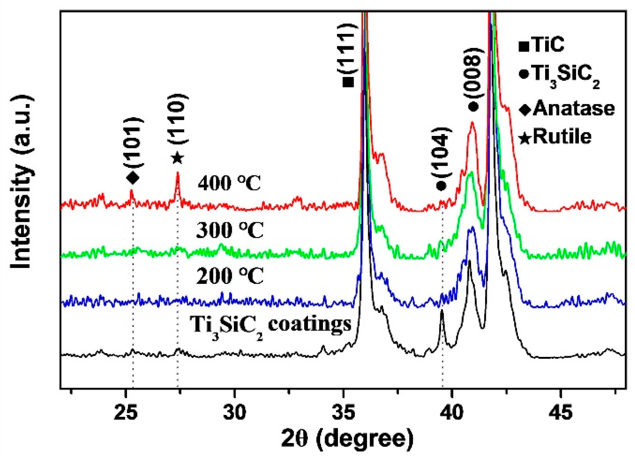
Figure 3.
Energy-dispersive X-ray spectroscopy (EDS) elemental scans taken from the surface at 200 °C for 3 h.
Figure 3.
Energy-dispersive X-ray spectroscopy (EDS) elemental scans taken from the surface at 200 °C for 3 h.

Figure 4.
EDS elemental scans taken from (a) the surface and (b) the cross-section of a sample oxidized at 400 °C for 1 h.
Figure 4.
EDS elemental scans taken from (a) the surface and (b) the cross-section of a sample oxidized at 400 °C for 1 h.
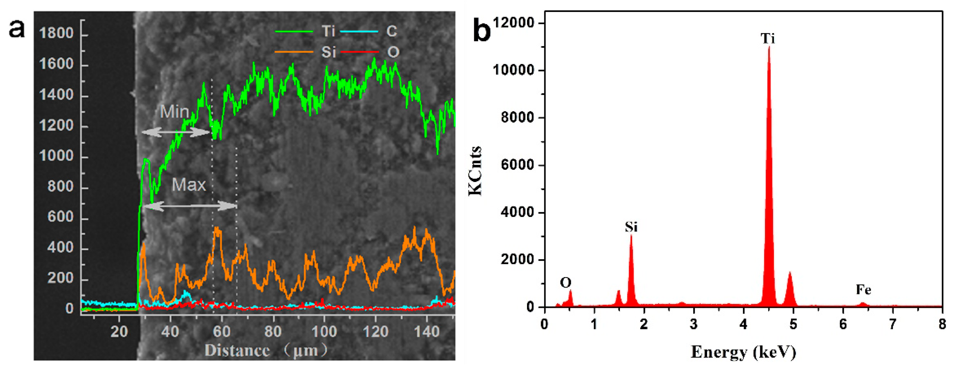
Figure 5.
(a) Average composition of element O in oxidized surfaces and (b) thickness of oxide layers under various thermal-oxidation treatments.
Figure 5.
(a) Average composition of element O in oxidized surfaces and (b) thickness of oxide layers under various thermal-oxidation treatments.

Figure 6.
Typical morphologies of microcracks of the samples oxidized at (a) 200 °C, (b) 300 °C, (c) and (d) 400 °C for 1 h, and (e) no thermal treatment.
Figure 6.
Typical morphologies of microcracks of the samples oxidized at (a) 200 °C, (b) 300 °C, (c) and (d) 400 °C for 1 h, and (e) no thermal treatment.
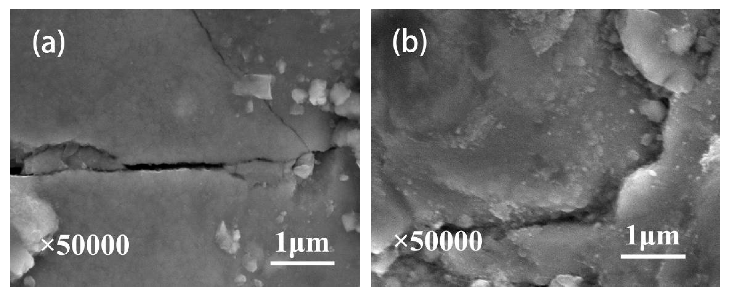

Figure 7.
T-θ curves of thermal oxidation-treated samples under the oxidation temperature of 400 °C as a function of the number of cycles
Figure 7.
T-θ curves of thermal oxidation-treated samples under the oxidation temperature of 400 °C as a function of the number of cycles
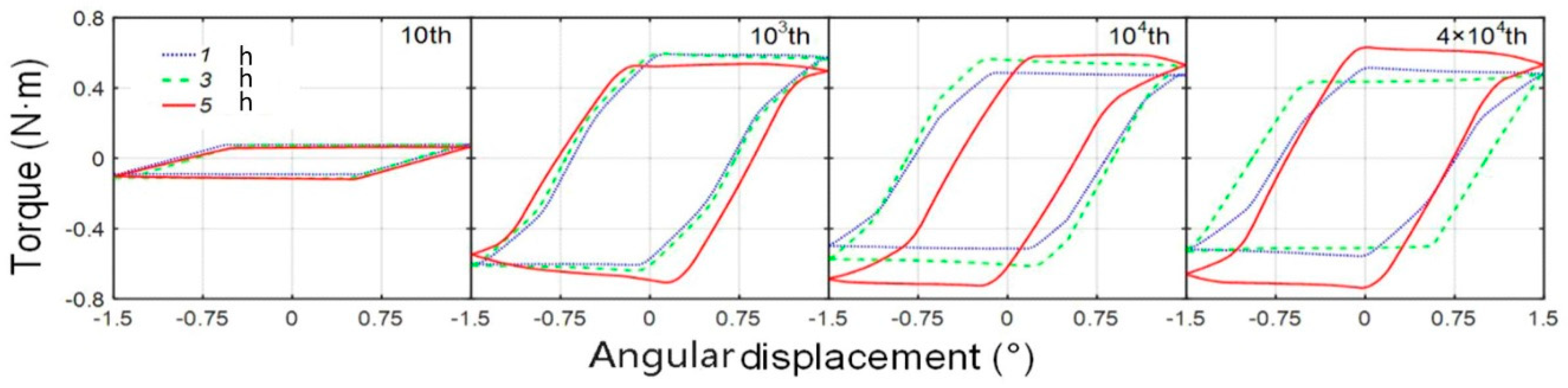
Figure 8.
Friction coefficients of thermal oxidation-treated samples under the oxidation temperature of (a) 200 °C, (b) 300 °C, and (c) 400 °C as a function of the number of cycles. Roughness of thermal oxidation-treated samples under the oxidation temperature of (d) 300 °C.
Figure 8.
Friction coefficients of thermal oxidation-treated samples under the oxidation temperature of (a) 200 °C, (b) 300 °C, and (c) 400 °C as a function of the number of cycles. Roughness of thermal oxidation-treated samples under the oxidation temperature of (d) 300 °C.
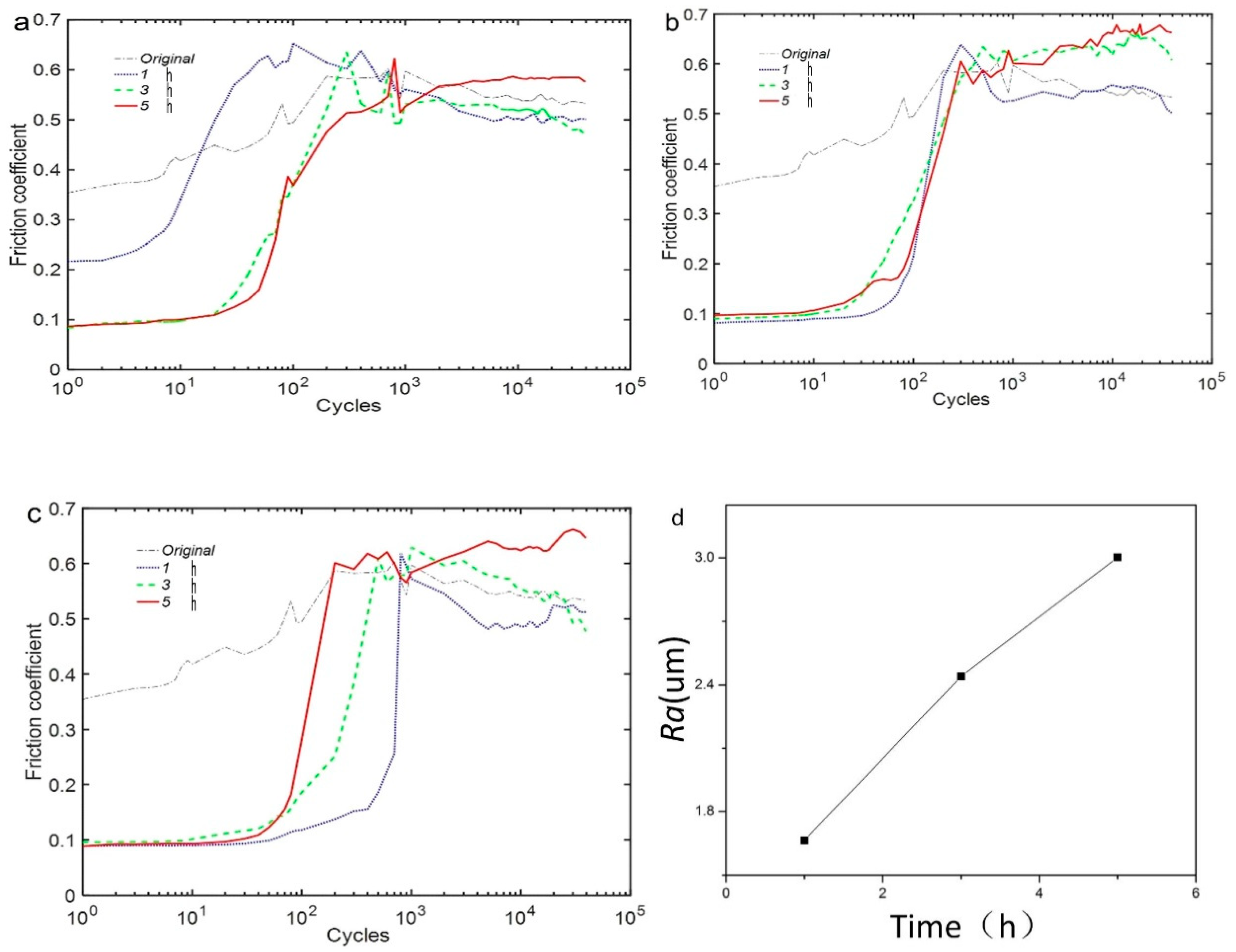
Figure 9.
Wear volume of oxidized coatings under various thermal-oxidation treatments.

Figure 10.
Scanning electron microscope (SEM) morphologies of the wear scars of coatings after the oxidation temperature of 200 °C: (a) 1 h and 5000× magnification; (b) 3 h and 5000× magnification; (c) 5 h and 5000× magnification; and (d) 5 h and 50,000× magnification; (e) EDS analysis of the wear scars under the oxidation time of 1 h.

Figure 11.
SEM morphologies of the wear scars of coatings after the oxidation temperature of 300 °C: (a) 1 h and 5000× magnification; (b) 3 h and 5000× magnification; and (c) 5 h and 5000× magnification.
Figure 11.
SEM morphologies of the wear scars of coatings after the oxidation temperature of 300 °C: (a) 1 h and 5000× magnification; (b) 3 h and 5000× magnification; and (c) 5 h and 5000× magnification.

Figure 12.
SEM morphologies of the wear scars of coatings after the oxidation temperature of 200 °C: (a) 1 h and 5000× magnification; (b) 1 h and 50,000× magnification; (c) 3 h and 5000× magnification; (d) 3 h and 50,000× magnification; (e) 5 h and 5000× magnification; and (f) 5 h and 50,000× magnification.

© 2018 by the authors. Licensee MDPI, Basel, Switzerland. This article is an open access article distributed under the terms and conditions of the Creative Commons Attribution (CC BY) license (http://creativecommons.org/licenses/by/4.0/).
Share and Cite
MDPI and ACS Style
Wang, J.; Luo, X.; Sun, Y. Torsional Fretting Wear Properties of Thermal Oxidation-Treated Ti3SiC2 Coatings. Coatings 2018, 8, 324. https://doi.org/10.3390/coatings8090324
AMA Style
Wang J, Luo X, Sun Y. Torsional Fretting Wear Properties of Thermal Oxidation-Treated Ti3SiC2 Coatings. Coatings. 2018; 8(9):324. https://doi.org/10.3390/coatings8090324
Chicago/Turabian StyleWang, Jian, Xiaohui Luo, and Yanhua Sun. 2018. "Torsional Fretting Wear Properties of Thermal Oxidation-Treated Ti3SiC2 Coatings" Coatings 8, no. 9: 324. https://doi.org/10.3390/coatings8090324
Note that from the first issue of 2016, this journal uses article numbers instead of page numbers. See further details here.