Improvement of Corrosion Resistance of Hastelloy-N Alloy in LiF-NaF-KF Molten Salt by Laser Cladding Pure Metallic Coatings

1
School of Mechanical Engineering, University of South China, Hengyang 421001, China
2
Shanghai Institute of Applied Physics, Chinese Academy of Sciences, Shanghai 201800, China
*
Authors to whom correspondence should be addressed.
Coatings 2018, 8(9), 322; https://doi.org/10.3390/coatings8090322
Submission received: 9 August 2018
/
Revised: 6 September 2018
/
Accepted: 12 September 2018
/
Published: 14 September 2018
Abstract
:The corrosion protection of Hastelloy-N alloy in LiF-NaF-KF (commonly referred to as FLiNaK) molten salt has been developed by pure Ni and Co coatings using the laser cladding technique. An immersion experiment with samples was performed in molten FLiNaK salt at 900 °C for 100 h. It was found that the corrosion rates of the pure Ni-coated specimen and the pure Co-coated specimen are 39.9% and 35.7% of that of Hastelloy-N alloy, respectively. A careful microstructural characterization indicates that a selective dissolution of the elemental Cr occurred in the surface of bare Hastelloy-N alloy, showing a severe intergranular corrosion. For pure metal-coated specimens, in contrast, only metal oxide formed during the laser cladding process dissolved into the molten fluoride salt. The dense pure metal (Ni or Co) coatings exhibit a slightly general corrosion and protect the Hastelloy-N substrate effectively. The possible corrosion mechanism for both coated and uncoated Hastelloy-N under the current experimental condition are discussed in this work.
1. Introduction
Ternary LiF-KF-NaF (FLiNaK, with molar ratio of 46.5:11.5:42.0) molten salt, one of the most promising candidate fluids for the high-temperature heat transfer, exhibits a series of advantages including high-temperature stability (>1000 °C), high thermal conductivity, high specific heat, high boiling point, and low viscosity [1,2,3,4]. FLiNaK molten salt can be used not only as a secondary coolant and a primary simulation coolant in molten salt reactors [5,6], but also as a primary coolant in advanced high-temperature reactors and heat transfer fluid in next-generation concentrated solar power systems [7]. However, one critical limitation for the FLiNaK molten salt is of intrinsically extremely corrosive at high temperatures [8]. Moreover, the corrosion will be aggravated due to the presence of impurities in the FLiNaK molten salt [8]. Therefore, the corrosion control has been a main concern for the materials applied in molten fluoride salts.
Hastelloy-N alloy, a Ni-based superalloy with a low Cr content developed by Oak Ridge National Laboratory (ORNL, Oak Ridge, TN, USA), has been demonstrated to be compatible with molten fluoride salt below 700 °C [9,10,11]. Some applications such as the hot side for the reactor-to-hydrogen-production-plant heat transfer system, however, are expected to reach over 800 °C [11,12]. To improve the corrosion resistance of Ni-based materials in the molten fluoride salt at high operating temperatures, some surface coating technologies have been developed [13,14,15,16,17]. For instance, Olson et al. [13] and Zhang et al. [14] reported the Ni electroplating layers on Incoloy-800 as active metal dissolution resistance [13,14]. Muralidharan et al. [15] reported the pure Ni coating on Inconel 617 by laser cladding and chemical vapor deposition. A two-step spraying and carburization technique was developed by Brupbacher et al. to prepare binder-free Cr3C2 coatings on Haynes-230 [16]. In our previous study, we have prepared AlN coatings by laser cladding on Hastelloy-N alloy offering superior corrosion resistance in LiF-KF-NaF molten salt [17]. In comparison with traditional surface coating techniques, laser cladding can directly produce dense coatings by melting and solidification of powders on a metallic substrate to improve the surface properties. It has many attractive merits such as high efficiency, strong metallurgical bonding, highly fined microstructure and easily tailored coating thickness [18].
Regarding the coating matrix, Luke et al. [19] calculated the Gibbs free energies in forming various metal fluorides at 850 °C and reported the following increasing tendency: CoF3 < MoF3 < NiF2 < CoF2 < CrF3 < CrF2 < KF < NaF < LiF. It is worth mentioning that the pure Mo exhibits poor oxidation resistance above 600 °C [20], and the element Cr is of extremely chemical activity in the molten fluoride salt [5,17,19,20,21]. Therefore, both pure Mo and Cr are not suitable for the coatings applied in the high-temperature molten fluoride salt. Specifically, the Gibbs free energies of formation for Ni fluoride (NiF2, 505.991 kJ/mol) and Co fluoride (CoF2 658.289 kJ/mol, CoF3 378.721 kJ/mol) are much lower than that of the major components of the molten salt (LiF, NaF, KF, >900 kJ/mol) [19]. It is, therefore, reasonable to expect that pure Ni and Co coatings are free from chemical attacks in the molten fluoride salt. Although Ni coating on Inconel 617 was prepared by the laser-cladded technology, no further experimental studies were conducted in molten salt. Particularly to our best knowledge, the metallic Co coating has not been employed on Ni-based alloy up to date.
In view of the Gibbs free energies of formation for Ni/Co fluorides as well as the similar melting points between the pure Ni/Co coating and the Ni-based Hastelloy-N alloy substrate [22], in this work, we have developed a laser-cladding technique to deposit pure Ni or Co metallic coatings on the Hastelloy-N alloy for the corrosion resistance improvement. A static corrosion test at 900 °C for 100 h was conducted to preliminarily evaluate the performance of the pure Ni and Co metallic coatings. The possible corrosion processes of such Hastelloy-N alloy with and without laser-cladded pure Ni and Co metallic coatings is discussed. This work is aimed to provide insights into the understanding of materials corrosion control technology.
2. Materials and Methods
2.1. Materials
A Ni-based Hastelloy-N alloy was selected as the substrate with the dimension of 60 × 60 × 5 mm3. The chemical composition of Hastelloy-N alloy is shown in Table 1. Gas atomized Ni and Co powders with purity of 99.9%, density of 3.9 g/cm3 and average size of 75 μm (Changsha Tianjiu Materials Ltd., Changsha, China) were used for laser cladding. High-purity FLiNaK molten salt was provided by Shanghai Institute of Applied Physics, Chinese Academy of Sciences (Shanghai, China), and detailed information can be referred to in our previous study [17].
2.2. Coating Preparation
Pure Ni or Co metallic coating was prepared by a laser cladding synchronous powder feeding technology using TJ-HL-T5000 5 kW CO2 laser (Wuhan Unity Laser Co., Ltd., Wuhan, China). By melting the metal powders, materials were deposited and built up layer by laser as the laser beam moves side-by-side as schematically shown in Figure 1. The laser parameters were controlled as follows: laser power 2.1 kW, laser scanning speed 6.0 mm/s, laser beam diameter 3.0 mm, multi-tracking overlapping rate 50.0%, powder feeding rate 6.5 g/min, and an Ar flow rate 40.0 L/min. The coating thickness on Hastelloy-N alloy is about 2.0 mm.
2.3. Characterization
Corrosion tests were carried out at 900 °C for 100 h, and the detailed experimental procedure was provided in our previous work [17]. Weight loss method was used to determine the corrosion rate (R) of the specimens after corrosion using the following formula [17,23]:
where m0 and m1 are the mass of the specimen before and after corrosion, respectively, and S0 is the corrosion area of the specimen.
R = (|m0 − m1|)/S0
Phase constituents of the specimens were investigated by a X-D6 X-ray diffractometer (XRD, Beijing Purkinje General Instrument Co., Ltd., Beijing, China) with Cu Kα radiation (λ = 1.5418 Å). Careful microstructural characterization was performed using a ZEISS MERLIN Compact scanning electron microscope (SEM, Carl Zeiss AG, Oberkochen, Germany) equipped with an Oxford energy-dispersive X-ray spectroscope (EDS).
3. Results and Discussion
3.1. Corrosion Behavior
Table 2 presents the weight loss of Hastelloy-N alloy and pure Ni or Co-coated specimens after corrosion testing in FLiNaK molten salt at 900 °C for 100 h. The results show that the corrosion rates of Hastelloy-N alloy, Ni-coated specimen and Co-coated specimen are 0.3164 ± 0.0002 mg/mm2, 0.1263 ± 0.0003 mg/mm2 and 0.1129 ± 0.0001 mg/mm2, respectively. It is apparent that the coated specimens exhibit superior corrosion resistance in contrast with the original Hastelloy-N alloy; and the pure Co-coated specimen is of the optimum corrosion resistance with a 35.7% weight loss of Hastelloy-N substrate. It is well demonstrated that the coatings act as a barrier layer to protect the Hastelloy-N substrate from the attack in molten fluoride salt effectively.
Surface SEM images of Hastelloy-N alloy, Ni-coated specimen and Co-coated specimen before and after corrosion are shown in Figure 2. The original Hastelloy-N alloy is of homogeneous microstructure with grain size of 50~100 μm, and some grey M6C particles distributed in the matrix (Figure 2a). After corrosion test, a severe intergranular corrosion is clearly observed in Figure 2b. The high-energy grain boundaries may become a rapid diffusion channel for element Cr; and the voids formed along the grain boundary due to the aggregation of vacancies left by the outward diffusion of Cr [17,19,20,21]. In contrast, the Ni or Co coating on Hastelloy-N alloy is of homogeneous microstructure before and after corrosion test (Figure 2c–f). There is only slight general corrosion occurred in the pure Ni or Co-coated specimen. It is evident that the Ni or Co coating can effectively improve the high-temperature corrosion resistance of the Hastelloy-N alloy in the molten salt. This is in good agreement with the corrosion weight loss results listed in Table 2.
3.2. Phase Analysis
Figure 3 shows the phase constituents of both the uncoated and coated specimens before and after corrosion. Hastelloy-N alloy is composed of γ-Ni and M6C phases (M represents the metal elements such as Ni, Mo and Cr), with a precipitation of new Cr9Mo21Ni20 phase after corrosion (Figure 3a) [17]. From Figure 3b, the original pure Ni-coated specimen is mainly composed of γ-Ni and a small amount of oxides (NiO, Cr2O3). The oxides were probably formed by simultaneously melting Ni powders and the Hastelloy-N surface under the action of the high-temperature laser beam. Comparatively, only γ-Ni phase remains while the oxide peaks disappeared after corrosion. For the pure Co-coated specimens, the pre-corrosion specimen is mainly composed of γ-Co and a few Cr2O3; while only γ-Co phase exists after corrosion. This is consistent with the conclusion that the metal oxides are thermodynamically unstable in the molten fluoride salt [4,23,24,25,26]. For better understanding the formation and dissolution of the metal oxides, the possible chemical reactions and the corresponding Gibbs free energies are given in Table 3. It is apparent that the Gibbs free energy of formation of Cr2O3 is much lower than those of NiO or CoO, indicating that Cr2O3 is of highest formability. The element Cr was inevitably diffused from the Hastelloy-N substrate during the high-temperature laser cladding process, which explains the occurrence of Cr2O3 in the coated specimens. Actually, Cr2O3 oxide can be easily generated on the surface of the Ni-based alloy exposed to the high temperature and oxygen-containing environment [27]. The formation of Cr2O3 oxide can protect the base material from further oxidation [27]. Therefore, the peaks corresponding to NiO in the Ni-coated specimen are very weak (Figure 3b). The absence of the Co-bearing oxide in the Co-coated specimen is probably due to the low content exceeding the detection limit of XRD (Figure 3c). More importantly, only pure γ-Ni or γ-Co phase is detected from the coated specimens after corrosion. This suggests that the oxides dissolved into the molten fluoride salt, and the possible reactions can be found in Table 3. The negative Gibbs free energies suggest the spontaneous reaction of the oxide dissolution. Therefore, the pure metallic coatings can provide substantial protection against the elemental diffusion from the substrate, and consequently improve the corrosion resistance of the Hastelloy-N alloy in the molten fluoride salt.
To further reveal the change in the elemental distribution of the cross-section specimens before and after corrosion, EDS line scanning was carried out and the results are shown in Figure 4. It can be seen from Figure 4a,b that there is an obvious concentration gradient for element Cr from the surface to the center. This is consistent with other reports regarding the element Cr in Hastelloy-N alloy reacting and dissolving in the molten salt initially to produce a Cr-depleted surface layer [3,28,29]. Meanwhile, Ni and Mo elements are relatively stable; and there are many Mo-enriched peaks corresponding to the presence of M6C particles after corrosion. This is consistent with the XRD result in Figure 3a and surface SEM result in Figure 2a,b.
For the coated specimens as shown in Figure 4c–f, all the elements are well preserved without obvious loss after corrosion, showing that both the pure metallic coatings are highly protective to the substrate in the molten salt. Notably, there are two peaks designated in Figure 4c,e, which correspond to the reflection of the Cr2O3 particles confirmed by XRD in Figure 3b,c before corrosion. However, such Cr2O3 peaks disappeared due to the dissolution or deduced concentration of particles after corrosion, which is consistent with the XRD results [4].
3.3. Microstructural Characterization
For better understanding the microstructure change of the specimens after the corrosion test, the detailed cross-section SEM observations were carefully performed. Figure 5 presents the SEM images under different magnifications of the cross-section Hastelloy-N alloy before and after corrosion. Similar to the surface observations shown in Figure 2a,b, the original Hastelloy-N alloy is composed of γ-Ni and M6C phases, showing a typical intergranular corrosion with a precipitation of new Cr9Mo21Ni20 phase after corrosion [17], as shown in Figure 5.
Figure 6 shows the cross-section SEM images of Ni-coated specimens before and after corrosion; and the quantitative EDS results of the characteristic particles marked in Figure 6 are presented in Table 4. The top laser-cladded Ni coating zone is of homogeneous microstructure with the thickness of about 2 mm (Figure 6a,b). However, some local corrosion occurred in the coating zone. The EDS result for the big black particles in Figure 6b is C0.91, N14.95, O22.47, Na3.68, K2.71, Cr1.64, Ni51.13 (at.%), which can be confirmed as the residual corrosion product on the specimen surface due to an inadequate cleaning after corrosion test. Figure 6a1,b1 correspond to the pre- and post-corrosion top Ni coating zone, respectively. It can be seen that some grey particles “1” and black particles “2” are present in the laser-cladded Ni coating zone (Figure 6a1), which can be determined as Cr2O3 and NiO in combination with EDS and XRD analysis results, respectively. These oxides were likely caused by the reaction with oxygen during the high-temperature laser cladding process in the atmospheric environment. It was reported that the diffusion rate of element Cr in Cr2O3 was approximately four orders of magnitude lower than that of in Ni [13]. Therefore, the presence of Cr2O3 particles may reduce the outward diffusion of Cr from the substrate into the molten salt.
However, there are only a few grey Cr2O3 particles as marked “3” and no black NiO particle is discernable after corrosion (Figure 6b1). This suggests that the oxides are unstable in the molten fluoride salt as reported by others [4,23,24,25,26]. In addition, the matrix is confirmed to be a γ-Ni solid solution with trace elements Mo and Cr diffusing from the substrate during the laser cladding process as marked “4”, immune from the molten salt attack, as demonstrated by EDS result and XRD result.
Figure 6a2,b2 show the SEM images taken from the coating/substrate bonding zones before and after corrosion, respectively. The laser-cladded pure Ni coating exhibits a good metallurgical bonding with the substrate as seen from Figure 5b. It is also clear that the coating in the bonding zone is characterized by columnar dendrites perpendicular to the interface along the heat flow direction, which is caused by the rapid solidification cooling of laser cladding under a composition gradient and a temperature gradient [5,18]. After corrosion in the molten salt, however, the interface between coating and substrate becomes hardly discernible and some tiny pores appear. In comparison with severe corrosion of the bare Hastelloy-N alloy in Figure 2 and Figure 5, there is only slight intergranular corrosion occurred in the substrate zone of the pure Ni-coated specimen as shown in Figure 6a3,b3. It is evident that the pure Ni coating can effectively improve the high-temperature corrosion resistance of the substrate in the molten salt.
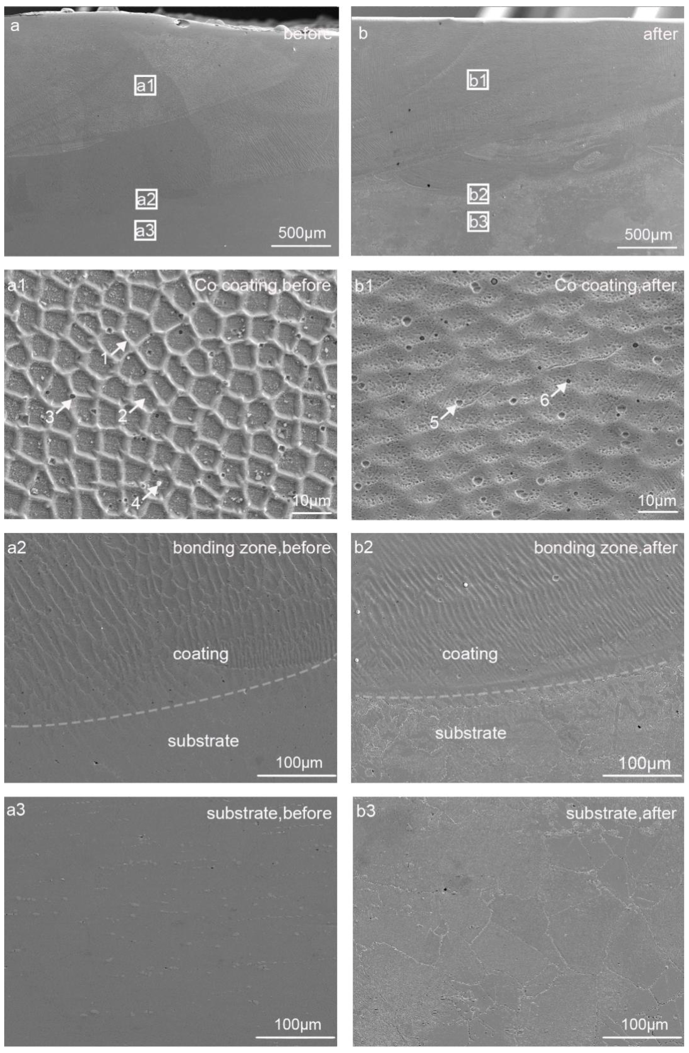
Figure 7 shows the cross-section SEM images of Co-coated specimen before and after corrosion, and EDS analysis of the characteristic particles marked in Figure 7 are presented in Table 5. In comparison to the Ni-coated specimen in Figure 7, the surface microstructure of the Co-coated specimen remains homogeneous without obvious corrosion as shown in the pre- and post-corrosion images (Figure 7a,b), respectively. The average coating thickness is about 1.60 mm. Figure 7a1–a3,b1–b3 display the three distinct zones for the laser-cladded Co-coated specimen. The top Co coating zone is characterized by a uniform network microstructure with some precipitated particles (Figure 7a1). There is similar composition for the network and the nanoscale particles inside the network marked as particles “1” and “2”, which is predominately consisted of Co; and a partial Ni diffusing from the Hastelloy-N substrate as listed in Table 5. Some black particles “3” with diameters of 0.5–1.0 μm could be confirmed as Cr2O3 particles by XRD and EDS analyses. Several big white particles “4” with high O and Si contents were also detected. After exposure in the molten fluoride salt, the post-corrosion Co-coated specimen exhibits a plain microstructure with the matrix “5”, similar composition as matrices “1” and “2”. At the same time, some black Cr2O3 particles “6” are still discernible in the post-corrosion coating zone (Figure 7b1), while no white Si-enrich particles were detected after corrosion. For the coating/substrate bonding zone, the coatings keep a good metallurgical bonding with the substrate even after corrosion, and the coating in the bonding zone exhibits a typical columnar dendritic microstructure as a result of laser heat flux in Figure 7a3,b2. Notably, in comparison to the Ni-coated specimen in Figure 6b2, the coating/substrate interface for the Co-coated specimen is free of pores and shows a superior bonding with the substrate (Figure 7b2). For the substrate zone as shown in Figure 7a3,b3, it exhibits the highest stability in the molten fluoride salt in this work.
3.4. Corrosion Mechanisms
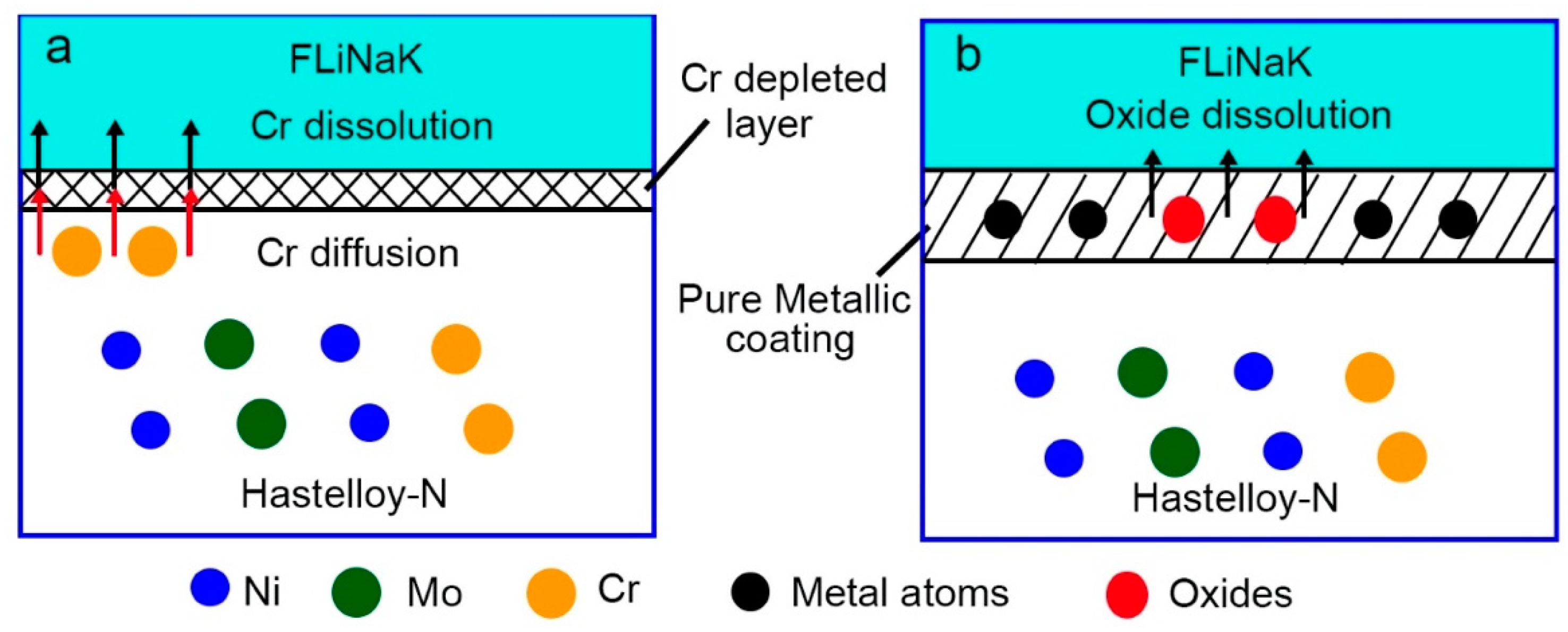
As noted from the above results, it is apparent that Hastelloy-N alloy with and without coatings exhibit different corrosion behaviors under the current experimental condition. Regardless of the possible impurity such as moisture and oxygen in FLiNaK molten salt, a schematic corrosion process of the uncoated and coated Hastelloy-N alloy is depicted in Figure 8. For the bare Hastelloy-N alloy as shown in Figure 8a, the element Cr diffuses and dissolves in the molten fluoride salt, leading to a Cr-depleted layer on the Hastelloy-N surface with severe corrosion. It is generally accepted, by ranking the Gibbs free formation energy of the respective metallic fluorides, that the activities of common metal elements into molten fluoride salt decrease in the following order: Al > Cr > Fe > Co > Ni > Mo > W [5,19]. Therefore, Cr in the Hastelloy-N substrate is expected to be easily dissolved in molten fluoride salt due to the highly negative Gibbs free energy of its fluoride phase as clearly shown in Figure 4b.
For the pure metal-coated specimens as shown in Figure 8b, in contrast, metal oxides formed during laser cladding process diffuse into the molten fluoride salt. The dense pure metal (Ni or Co) coating can effectively hinder the penetration of the molten fluoride and thus improve the corrosion resistance of the substrate. The laser-cladded Co specimen shows superior corrosion resistance in comparison to the Ni-coated specimen in this work, as shown in Figure 6b3 and Figure 7b3. This is possibly due to the fact that the Co fluoride in form of CoF3 is of smaller absolute value of Gibbs free energy (378.721 kJ/mol) than that of Ni fluoride (NiF2, 505.991 kJ/mol) [19]. However, it is noted that the elements from Hastelloy-N substrate did diffuse to the pure metallic coating during the laser cladding process, leading to the slightly general corrosion of the laser-cladded coatings and thus limiting the capabilities for long-term protection to some extent. A further purification of FLiNaK salt and an appropriate control of the substrate dilution are needed to ensure a better protective effect of the laser-cladded coating.
4. Conclusions
This study has developed the laser-cladded pure metallic coatings (Ni and Co) to improve the corrosion resistance of Hastelloy-N alloy in FLiNaK molten fluoride salt. Conclusions can be drawn as below:
- Superior corrosion resistance caused by pure Ni and Co metallic coatings. Pure metallic coatings can effectively improve the corrosion resistance of Hastelloy-N alloy in molten fluoride salt, which was confirmed by the much lower corrosion rate of the pure Ni- and Co-coated specimens than that of Hastelloy-N alloy. Significantly, the firstly-reported Co-coated specimen exhibits the optimal stability in the molten fluoride salt without any discernible corrosion.
- Unique microstructure for treated Hastelloy-N alloy. The Hastelloy-N alloy is composed of γ-Ni and M6C, and a new Cr9Mo21Ni20 precipitate after corrosion. In contrast, the pure Ni coating is mainly composed of γ-Ni, NiO, and Cr2O3, while the pure Co coating is mainly composed of γ-Co and Cr2O3. After corrosion in molten fluoride salt, only γ-Ni phase or γ-Co phase exists in the pure metallic coatings, respectively.
- Mechanism understanding on the corrosion behavior. The elemental Cr in Hastelloy-N diffuses and dissolves into the molten fluoride salt, leading to an elemental depleted layer on the alloy surface with severe intergranular corrosion. For pure metal-coated specimens, in contrast, only metal oxides formed during laser cladding process dissolve into the molten fluoride salt. The dense pure metal (Ni or Co) coatings can effectively hinder the penetration of the molten fluoride and thus improve the corrosion resistance of the substrate remarkably.
Author Contributions
Conceptualization, H.Z.; Writing—Original Draft Preparation, H.Z.; Investigation, B.L.; Data Curation, M.C.; Funding Acquisition, C.Q. and Z.T.
Funding
This research was funded by National Natural Science Foundation of China (No. 51474130), Research Foundation of Education Bureau of Hunan Province (No. 15K108), and Qinghai Major Science and Technology Projects (No. 2017-GX-A3).
Conflicts of Interest
The authors declare no conflict of interest.
References
- Holcomb, D.E.; Cetiner, S.M. An Overview of Liquid Fluoride Salt Heat Transport Systems; Report No. ORNL/TM-2010/156; Oak Ridge National Laboratory: Oak Ridge, TN, USA, 2010.
- Romatoski, R.R.; Hu, L.W. Fluoride salt coolant properties for nuclear reactor applications: A review. Ann. Nucl. Energy 2017, 109, 635–647. [Google Scholar] [CrossRef]
- Qiu, J.; Zou, Y.; Yu, G.J.; He, S.M.; Liu, W.G.; Jia, Y.Y.; Li, Z.J.; Xu, H.J. Speciation study of chromium corrosion product in molten LiF-NaF-KF salt. Nucl. Sci. Tech. 2015, 26, 60602. [Google Scholar]
- Ouyang, F.Y.; Chang, C.H.; Kai, J.J. Long-term corrosion behaviors of Hastelloy-N and Hastelloy-B3 in moisture-containing molten FLiNaK salt environments. J. Nucl. Mater. 2014, 446, 81–89. [Google Scholar] [CrossRef]
- Wang, Y.L.; Zeng, C.L.; Li, W.H. The influence of temperature gradient on the corrosion of materials in molten fluorides. Corros. Sci. 2018, 136, 180–187. [Google Scholar] [CrossRef]
- Ai, H.; Hou, J.; Ye, X.X.; Zeng, C.L.; Sun, H.; Li, X.; Yu, G.Y.; Zhou, X.T.; Wang, J.Q. Influence of graphite-alloy interactions on corrosion of Ni-Mo-Cr alloy in molten fluorides. J. Nucl. Mater. 2018, 503, 116–123. [Google Scholar] [CrossRef]
- Kuravi, S.; Trahan, J.; Goswami, D.Y.; Rahman, M.M.; Stefanakos, E.K. Thermal energy storage technologies and systems for concentrating solar power plants. Prog. Energy Combust. Sci. 2013, 39, 285–319. [Google Scholar] [CrossRef]
- Yin, H.Q.; Qiu, J.; Liu, H.J.; Liu, W.G.; Wang, Y.; Fei, Z.J.; Zhao, S.F.; An, X.H.; Cheng, J.H.; Chen, T.; et al. Effect of CrF3 on the corrosion behaviour of Hastelloy-N and 316L stainless steel alloys in FLiNaK molten salt. Corros. Sci. 2018, 131, 355–364. [Google Scholar] [CrossRef]
- Gu, Y.F.; Liu, J.X.; Wang, Y.; Xue, J.X.; Wang, X.G.; Zhang, H.B.; Xu, F.F.; Zhang, G.J. Corrosion behavior of TiC-SiC composite ceramics in molten FLiNaK salt. J. Eur. Ceram. Soc. 2017, 37, 2575–2582. [Google Scholar] [CrossRef]
- Cheng, H.W.; Leng, B.; Chen, K.; Jia, Y.Y.; Dong, J.S.; Li, Z.J.; Zhou, X.T. EPMA and TEM characterization of intergranular tellurium corrosion of Ni-16Mo-7Cr-4Fe superalloy. Corros. Sci. 2015, 97, 1–6. [Google Scholar] [CrossRef]
- Ye, X.X.; Ai, H.; Guo, Z.; Huang, H.F.; Jiang, L.; Wang, J.Q.; Li, Z.J.; Zhou, X.T. The high-temperature corrosion of Hastelloy N alloy (UNS N10003) in molten fluoride salts analysed by STXM, XAS, XRD, SEM, EPMA, TEM/EDS. Corros. Sci. 2016, 106, 249–259. [Google Scholar] [CrossRef]
- Cao, W.; Xia, S.; Bai, Q.; Zhang, W.Z.; Zhou, B.X.; Li, Z.J.; Jiang, L. Effects of initial microstructure on the grain boundary network during grain boundary engineering in Hastelloy N alloy. J. Alloys Compd. 2017, 704, 724–733. [Google Scholar] [CrossRef]
- Olson, L.; Sridharan, K.; Anderson, M.; Allen, T. Nickel-plating for active metal dissolution resistance in molten fluoride salts. J. Nucl. Mater. 2011, 411, 51–59. [Google Scholar] [CrossRef]
- Zhang, Y.C.; Liu, Y.H.; Zhou, Z.J.; Zheng, M.M.; Kong, S.Y.; Xia, H.H.; Li, H.L. Research on Protective Coating on Inner Surface of Alloy Tube. IOP Conf. Ser.: Mater. Sci. Eng. 2017, 230, 012018. [Google Scholar] [CrossRef] [Green Version]
- Muralidharan, G.; Wilson, D.F.; Walker, L.R.; Santella, M.L.; Holcomb, D.E. Cladding Alloys for Fluoride Salt Compatibility Final Report; Oak Ridge National Laboratory: Oak Ridge, TN, USA, 2011.
- Brupbacher, M.C.; Zhang, D.J.; Buchta, W.M.; Graybeal, M.L.; Rhim, Y.R.; Nagle, D.C.; Spicer, J.B. Synthesis and characterization of binder-free Cr3C2 coatings on nickel-based alloys for molten fluoride salt corrosion resistance. J. Nucl. Mater. 2015, 461, 215–220. [Google Scholar] [CrossRef]
- Zhu, H.M.; Li, B.C.; Chen, M.H.; Liu, Z.L.; Tang, Z.F.; Qiu, C.J. AlN coatings on Hastelloy-N alloy offering superior corrosion resistance in LiF-KF-NaF molten salt. J. Fluorine Chem. 2018, 213, 80–86. [Google Scholar] [CrossRef]
- Wang, H.Y.; Zhang, S.; Zhang, C.H.; Wu, C.L.; Zhang, C.B.; Abdullah, A.O. Effects of V and Cr on laser-cladded Fe-based coatings. Coatings 2018, 8, 107. [Google Scholar] [CrossRef]
- Olson, L.C.; Ambrosek, J.W.; Sridharan, K.; Anderson, M.H.; Allen, T.R. Materials corrosion in molten LiF-NaF-KF salt. J. Fluorine Chem. 2009, 130, 67–73. [Google Scholar] [CrossRef]
- Wang, Y.; Yan, J.H.; Wang, D.Z. High temperature oxidation and microstructure of MoSi2/MoB composite coating for Mo substrate. Int. J. Refract. Met. Hard Mater. 2017, 68, 60–64. [Google Scholar] [CrossRef]
- Dai, Q.L.; Ye, X.X.; Ai, H.; Chen, H.J.; Li, J.; Liang, J.P.; Yu, K.; Leng, B.; Li, Z.J.; Zhou, X.T. Corrosion of Incoloy 800H alloys with nickel cladding in FLiNaK salts at 850 °C. Corros. Sci. 2018, 133, 349–357. [Google Scholar] [CrossRef]
- Gale, W.F.; Totemeier, T.C. Thermochemical data. In Smithells Metals Reference Book, 8th ed.; Elsevier Butterworth-Heinemann: Burlington, MA, USA, 2004; pp. 24–26. [Google Scholar]
- Wang, Y.; Tang, Z.F.; Fu, Y.; Huang, S.R.; Zhao, S.F.; Zhang, P.; Xie, L.D.; Wang, X.G.; Zhang, G.J. Corrosion behavior of ZrC-SiC composite ceramics in LiF-NaF-KF molten salt at high temperatures. Ceram. Int. 2015, 41, 12996–13005. [Google Scholar] [CrossRef]
- Razik, N.A. Precise lattice constants determination of cubic crystals from X-ray powder diffractometric measurements. Appl. Phys. A 1985, 37, 187–189. [Google Scholar] [CrossRef]
- Wang, Y.L.; Liu, H.J.; Zeng, C.L. Galvanic corrosion of pure metals in molten fluorides. J. Fluorine Chem. 2014, 165, 1–6. [Google Scholar] [CrossRef]
- Watanabe, T.; Kondo, M.; Nagasaka, T.; Sagara, A. Corrosion characteristic of AlN, Y2O3, Er2O3 and Al2O3 in Flinak for molten salt blanket system. J. Plasma Fusion Res. SERIES 2010, 9, 342–347. [Google Scholar]
- Liu, L.F.; Wu, S.S.; Chen, Y.; Lu, S.L. Oxidation behavior of RE-modified nickel-based superalloy between 950 °C and 1150 °C in air. Trans. Nonferrous Met. Soc. Chin. 2016, 26, 1163–1169. [Google Scholar] [CrossRef]
- Liu, T.; Dong, J.S.; Wang, L.; Li, Z.J.; Zhou, X.T.; Lou, L.H.; Zhang, J. Effect of long-term thermal exposure on microstructure and stress rupture properties of GH3535 superalloy. J. Mater. Sci. Technol. 2015, 31, 269–279. [Google Scholar] [CrossRef]
- Liu, T.; Dong, J.S.; Xie, G.; Wang, L.; Lou, L.H. Effect of silicon on microstructure and stress rupture properties of a corrosion resistant Ni-based superalloy during long term thermal exposure. Mater. Sci. Eng. A. 2016, 656, 75–83. [Google Scholar] [CrossRef]
Figure 1.
Schematic of the laser cladding process.

Figure 2.
Surface SEM images of Hastelloy-N alloy (a,b), Ni-coated specimen (c,d) and Co-coated specimen (e,f) before and after corrosion.
Figure 2.
Surface SEM images of Hastelloy-N alloy (a,b), Ni-coated specimen (c,d) and Co-coated specimen (e,f) before and after corrosion.
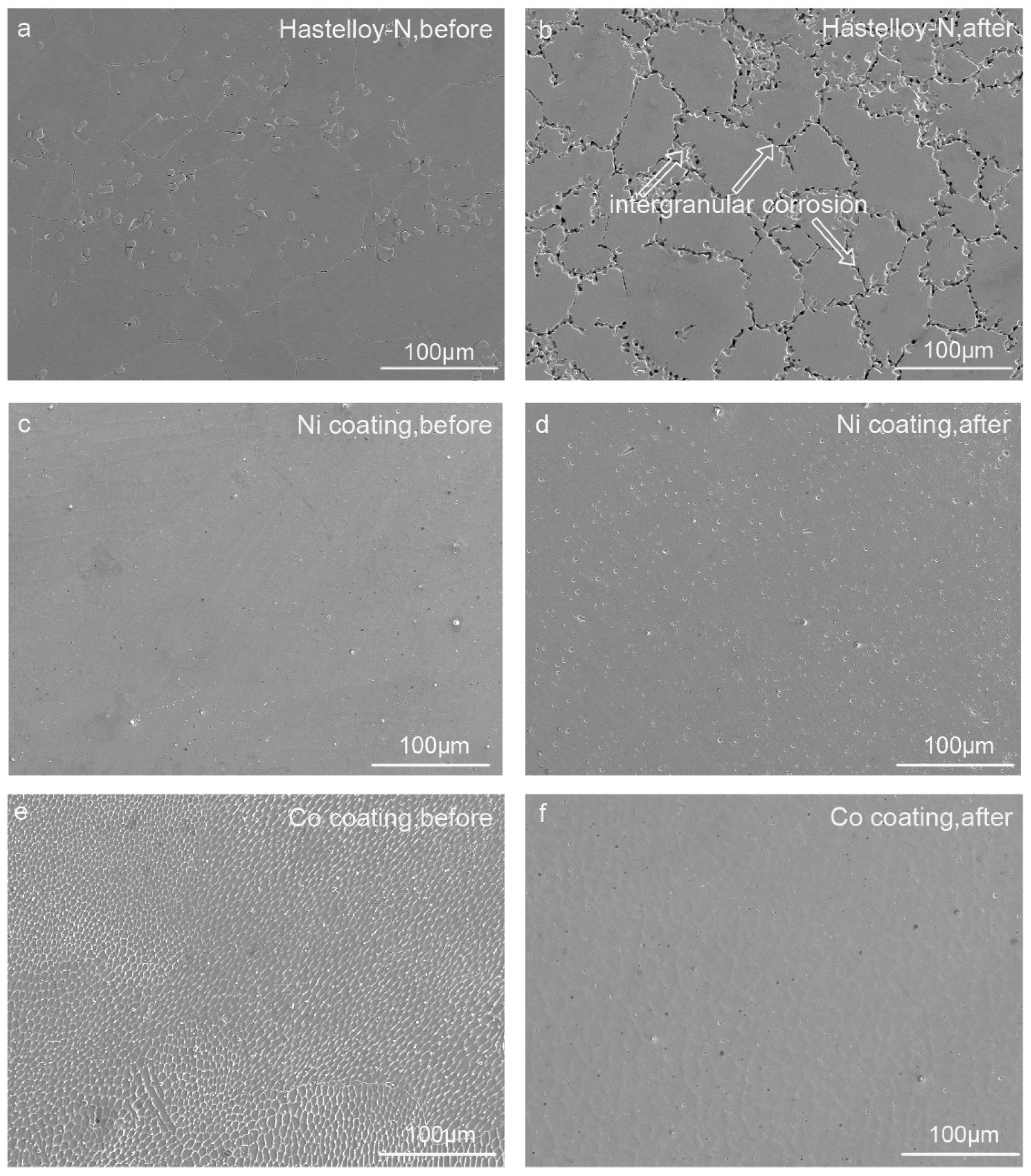
Figure 3.
Surface XRD spectra of the specimens before and after corrosion: (a) Hastelloy-N alloy; (b) Ni-coated specimen; (c) Co-coated specimen.
Figure 3.
Surface XRD spectra of the specimens before and after corrosion: (a) Hastelloy-N alloy; (b) Ni-coated specimen; (c) Co-coated specimen.
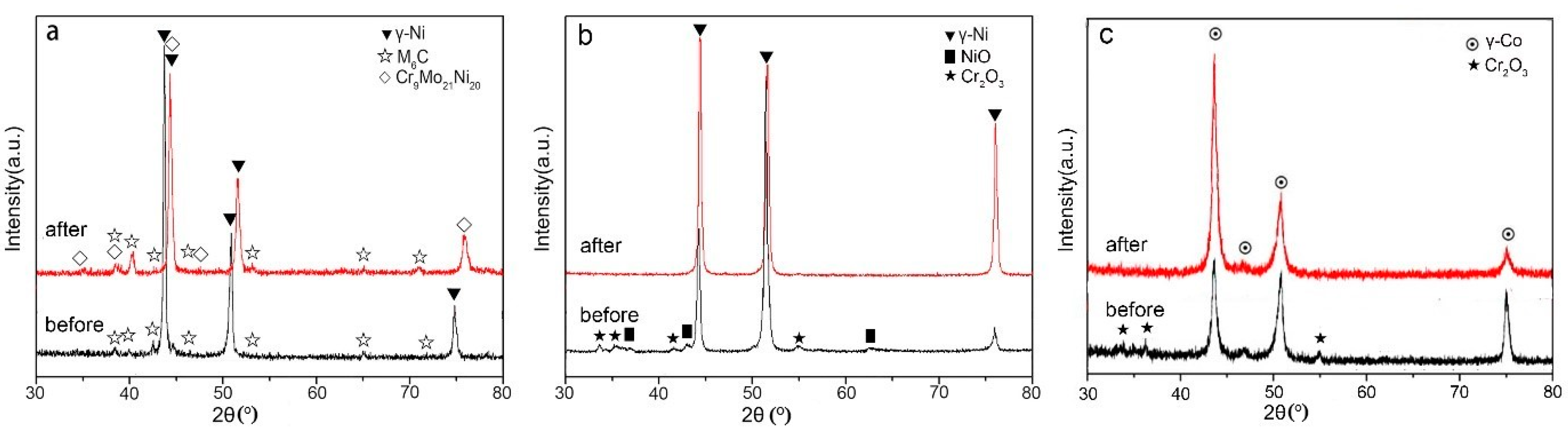
Figure 4.
Cross-section energy-dispersive X-ray spectroscope (EDS) line scanning maps of Hastelloy-N alloy (a,b), Ni-coated specimen (c,d) and Co-coated specimen (e) before and (f)after corrosion.
Figure 4.
Cross-section energy-dispersive X-ray spectroscope (EDS) line scanning maps of Hastelloy-N alloy (a,b), Ni-coated specimen (c,d) and Co-coated specimen (e) before and (f)after corrosion.

Figure 5.
Cross-section SEM images of Hastelloy-N alloy before (a,c) and after (b,d) corrosion.
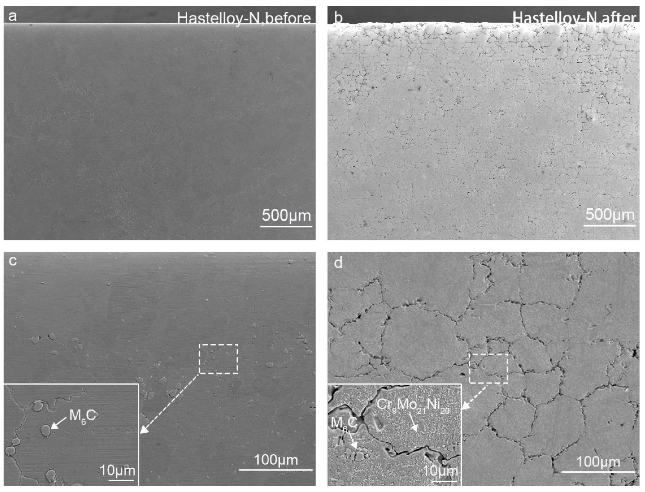
Figure 6.
Cross-section SEM images of the Ni-coated specimens (a) before corrosion and (b) after corrosion and the images with larger magnification: (a1,b1) coating zone; (a2,b2) coating/surface bonding zone; (a3,b3) substrate zone.
Figure 6.
Cross-section SEM images of the Ni-coated specimens (a) before corrosion and (b) after corrosion and the images with larger magnification: (a1,b1) coating zone; (a2,b2) coating/surface bonding zone; (a3,b3) substrate zone.
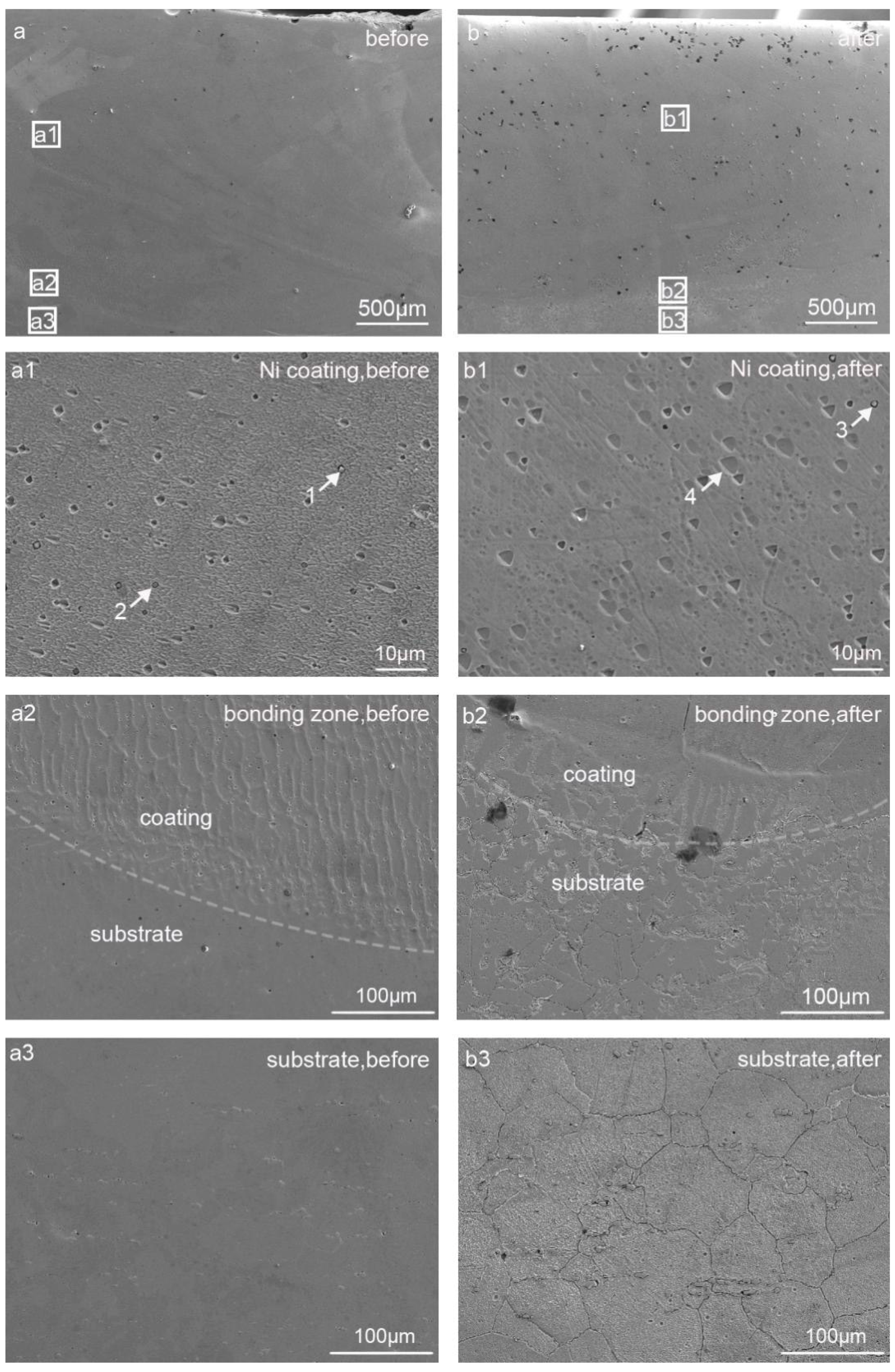
Figure 7.
Cross-section SEM images of the Co-coated specimens (a) before corrosion and (b) after corrosion and the images with larger magnification: (a1,b1) coating zone; (a2,b2) coating/surface bonding zone; (a3,b3) substrate zone.
Figure 7.
Cross-section SEM images of the Co-coated specimens (a) before corrosion and (b) after corrosion and the images with larger magnification: (a1,b1) coating zone; (a2,b2) coating/surface bonding zone; (a3,b3) substrate zone.

Figure 8.
Corrosion schematic of specimens during an exposure in FLiNaK molten salt at 900 °C for 100 h: (a) Hastelloy-N alloy; (b) pure metal-coated specimen.
Figure 8.
Corrosion schematic of specimens during an exposure in FLiNaK molten salt at 900 °C for 100 h: (a) Hastelloy-N alloy; (b) pure metal-coated specimen.


Table 1.
The chemical compositions of Hastelloy-N alloy (wt.%).
| Element | Ni | Cr | Mo | Fe | Mn | Al | W | Si | C |
| Mass Fraction (wt.%) | Balance | 7.01 | 16.80 | 4.16 | 0.52 | 0.28 | 0.20 | 0.36 | 0.06 |
Table 2.
Corrosion weight loss of specimens caused by corrosion after exposure to FLiNaK at 900 °C for 100 h under Ar atmosphere.
Table 2.
Corrosion weight loss of specimens caused by corrosion after exposure to FLiNaK at 900 °C for 100 h under Ar atmosphere.
| Specimens | Corrosion Weight Loss (mg/mm2) |
|---|---|
| Hastelloy-N Alloy | 0.3164 ± 0.0002 |
| Ni-Coated Specimen | 0.1263 ± 0.0003 |
| Co-Coated Specimen | 0.1129 ± 0.0001 |
Table 3.
The chemical reactions for the formation and dissolution of the metal oxides in the pure metal-coated specimens.
Table 3.
The chemical reactions for the formation and dissolution of the metal oxides in the pure metal-coated specimens.
| Oxides | Reactions for Oxide Formation during the Laser Cladding Process | Gibbs Free Energy of Formation of Oxides | Reactions and Gibb’s Free Energy in 900 °C for Oxide Dissolution in the Molten Fluoride Salt |
|---|---|---|---|
| Cr2O3 | 2Cr + 1.5O2 = Cr2O3 | = −1056.62 + 0.25349T | Cr2O3 + 6HF = 2CrF3 + 3H2O, ΔG = −106.254 kJ/mol |
| NiO | Ni + 0.5O2 = NiO | = −210.04 + 0.08467T | NiO + 2HF = NiF2 + H2O, ΔG = −55.779 kJ/mol |
| CoO | Co + 0.5O2 = CoO | = −210.17 + 0.06485T | CoO + 2HF = CoF2 + H2O, ΔG = −68.379 kJ/mol |
Table 4.
EDS analysis of the characteristic microstructures of the Ni-coated specimen in Figure 6.
Table 4.
EDS analysis of the characteristic microstructures of the Ni-coated specimen in Figure 6.
| Particles | Element (at.%) | ||||||||
|---|---|---|---|---|---|---|---|---|---|
| C | O | Ni | Cr | Si | Fe | Mo | Mn | Al | |
| 1 (Cr2O3) | 0.07 | 65.10 | 5.60 | 17.53 | 3.98 | – | – | 4.96 | 2.76 |
| 2 (NiO) | 0.05 | 52.60 | 29.49 | 2.01 | 7.84 | – | 0.72 | 0.72 | 6.60 |
| 3 (Cr2O3) | 0.06 | 66.22 | 2.52 | 23.42 | – | – | – | – | 7.77 |
| 4 (γ-Ni) | 0.08 | – | 95.16 | 1.90 | – | 1.81 | 1.05 | – | – |
Table 5.
EDS analysis of the characteristic microstructures of the Co-coated specimen in Figure 7.
Table 5.
EDS analysis of the characteristic microstructures of the Co-coated specimen in Figure 7.
| Particles | Element (at.%) | |||||||||
|---|---|---|---|---|---|---|---|---|---|---|
| C | O | Co | Ni | Cr | Si | Fe | Mo | Mn | Al | |
| 1 (γ-Co) | 0.06 | – | 57.74 | 31.41 | 2.86 | – | 1.60 | 6.09 | – | – |
| 2 (γ-Co) | 0.15 | – | 58.58 | 31.43 | 3.28 | – | 1.97 | 4.59 | – | – |
| 3 (Cr2O3) | 0.06 | 68.89 | 2.81 | 1.05 | 11.72 | 9.83 | – | 0.42 | 3.57 | 1.65 |
| 4 | 0.04 | 61.98 | 4.85 | 2.40 | 4.98 | 16.03 | – | 0.81 | 5.34 | 3.56 |
| 5 (γ-Co) | 0.10 | – | 56.61 | 33.47 | 2.66 | – | 1.96 | 5.19 | – | – |
| 6 (Cr2O3) | 0.03 | 55.80 | 11.59 | 6.57 | 7.71 | 12.53 | 0.64 | 0.99 | 3.61 | 0.54 |
© 2018 by the authors. Licensee MDPI, Basel, Switzerland. This article is an open access article distributed under the terms and conditions of the Creative Commons Attribution (CC BY) license (http://creativecommons.org/licenses/by/4.0/).
Share and Cite
MDPI and ACS Style
Zhu, H.; Li, B.; Chen, M.; Qiu, C.; Tang, Z. Improvement of Corrosion Resistance of Hastelloy-N Alloy in LiF-NaF-KF Molten Salt by Laser Cladding Pure Metallic Coatings. Coatings 2018, 8, 322. https://doi.org/10.3390/coatings8090322
AMA Style
Zhu H, Li B, Chen M, Qiu C, Tang Z. Improvement of Corrosion Resistance of Hastelloy-N Alloy in LiF-NaF-KF Molten Salt by Laser Cladding Pure Metallic Coatings. Coatings. 2018; 8(9):322. https://doi.org/10.3390/coatings8090322
Chicago/Turabian StyleZhu, Hongmei, Baichun Li, Minghui Chen, Changjun Qiu, and Zhongfeng Tang. 2018. "Improvement of Corrosion Resistance of Hastelloy-N Alloy in LiF-NaF-KF Molten Salt by Laser Cladding Pure Metallic Coatings" Coatings 8, no. 9: 322. https://doi.org/10.3390/coatings8090322
Note that from the first issue of 2016, this journal uses article numbers instead of page numbers. See further details here.