Article

Synthesis, Characterization, and Application of Novel Ni-P-Carbon Nitride Nanocomposites

1
Center for Advanced Materials, Qatar University, Doha 2713, Qatar
2
Department of Metallurgical and Materials Engineering, Faculty of Petroleum and Mining Engineering, Suez University, Suez 43721, Egypt
3
Department of Mechanical Engineering, Dalhousie University, Halifax, NS B3J 2X4, Canada
*
Author to whom correspondence should be addressed.
Permanent address: Physical Chemistry Department, National Research Center, Dokki, Giza 12622, Egypt.
Coatings 2018, 8(1), 37; https://doi.org/10.3390/coatings8010037
Submission received: 28 November 2017 / Revised: 10 January 2018 / Accepted: 15 January 2018 / Published: 17 January 2018

Abstract

:
Dispersion of 2D carbon nitride (C3N4) nanosheets into a nickel phosphorous (NiP) matrix was successfully achieved by ultrasonication during the electroless plating of NiP from an acidic bath. The morphology and thickness, elemental analysis, phases, roughness, and wettability for as-plated and heat-treated nanocomposite were determined by scanning electron microscopy, energy-dispersive X-ray spectroscopy, X-ray diffraction, atomic force microscopy, and contact angle measurements, respectively. C3N4 showed a homogeneous distribution morphology in the nanocomposite that changed from amorphous in case of the NiP to a mixed crystalline-amorphous structure in the NiP-C3N4 nanocomposite. The microhardness and corrosion resistance of the as-plated nanocomposite and the heat-treated nanocomposite coating were significantly enhanced compared to the Ni-P. The nanocomposite showed a superior corrosion protection efficiency of ~95%, as observed from the electrochemical impedance spectroscopy (EIS) measurements. On the other hand, the microhardness of the nanocomposite was significantly increased from 780 to reach 1175 HV200 for NiP and NiP-C3N4, respectively.

Graphical Abstract

1. Introduction

Enhancing the corrosion protection for oil and gas pipelines continues to motivate intensive research efforts to find new coatings or modify the existing ones. Electroless deposited NiP coatings, obtained by an autocatalytic process, are characterized by a combination of many unique properties such as good wear and corrosion protection efficiency, uniformity of coating thickness, and a higher hardness [1]. These properties opened the field for NiP to be used in different industries [2]. However, to improve these properties, the incorporation of nanoparticles in the NiP matrix has been tried extensively recently [3,4,5,6,7,8]. The performance of the co-deposition of hard second-phase nanoparticles such as Al2O3, TiN, B4C, ZrO2, SiC, TiO2, CNT, graphite, and diamond [9,10,11,12,13,14,15,16,17] with the Ni-P matrix was investigated, and has shown an enhancement in terms of microhardness, as well as corrosion and wear resistances. Nevertheless, the Ni-P matrix with the insertion of the carbon nitride (C3N4) nano-sheets has not been reported. The prediction of the possible existence of the C3N4 compound is credited to Cohen and Liu [18,19]. Due to its high hardness and excellent thermal and chemical stability, C3N4 has attracted significant interest. C3N4 properties are essentially the same as those of diamond [20], i.e., the mechanical and tribological characteristics, as well as the corrosion resistance of its composite coatings, are expected to be excellent [21]. The goal of the present study is to prepare a new NiP-C3N4 nanocomposite with better corrosion resistance and mechanical properties through the incorporation of 2D C3N4 nanosheets during the electroless deposition of the NiP alloy. In addition, a comparative study between the new nanocomposite and the original C3N4-free alloy will be carried out to show the superior performance of the electroless deposited NiP-C3N4 nanocomposite compared to the NiP alloys.

2. Experimental

2.1. Materials, Solutions, and Preparation

Electroless NiP and NiP-C3N4 nanocomposite coatings were deposited on an API X120 C-steel that was starting to be used recently in the oil and gas industry. The chemical composition (in wt %) of the API X120 steel that purchased from Tianjin Tiangang Guanye Co., Ltd., (Tianjin, China) is shown in Table 1.
Prior to the electroless deposition, the specimens were grinded with different grits of emery paper up to 2000, then polished with micro-polish alumina suspension (1 and 3 µm) to obtain a mirror finishing surface. After that degreasing the specimens in ultrasonicated acetone bath for 15 min was done, followed by alkaline cleaning for 5 min at 80 °C then electro-alkaline cleaning for 2 min at 70 °C with I = 2 A·cm−2 and acid etching in 15 wt % H2SO4 solution for 20 s. The used alkaline cleaning solution consists of 50 g·L−1 NaOH, 30 g·L−1 Na2CO3 and 30 g·L−1 Na3PO4 while that used in electro-alkaline cleaning consists of 15 g·L−1 NaOH, 25 g·L−1 Na2CO3 and 25 g·L−1 Na3PO4.
After each of the pretreatment steps, the specimens were washed with deionized water. Pretreated substrate coupons of 20 × 30 × 10 mm3 were used in the electroless deposition process. All used solutions are analytical-grade reagents from Sigma-Aldrich (St. Louis, MO, USA).
The electroless bath for the NiP coating contained 15 g·L−1 NiSO4·6H2O, 30 g·L−1 NaH2PO2·H2O, 20 g·L−1 lactic acid, 20 g·L−1 citric acid, and 0.002 g·L−1 thiourea, while the electroless NiP-C3N4 nanocomposite coating bath contained 15 g·L−1 NiSO4·6H2O, 30 g·L−1 NaH2PO2·H2O, 15 g·L−1 ammonium chloride, 30 g·L−1 sodium citrate, and 0.002 g·L−1 thiourea. NaOH was used to adjust the pH of the NiP and NiP-C3N4 plating baths to 4.5 and 8, respectively. The two baths were maintained at 85 °C. To obtain well-suspended C3N4 nanosheets, which are synthesized and characterized in our previous work [22], in the electroless bath, 0.5 g of C3N4 was added to a 100 mL of the plating solution that includes also 0.02 g·L−1 of sodium dodecyl sulfate as the surfactant. Then, the solution was mixed with ultrasonic probe for 2 h. Finally, the mixture was poured into the original plating bath stirred at 300 rpm using a magnetic stirrer. The coupons were immersed in the bath and the plating process lasted for 2 h. Then, the coupons were removed from the bath, rinsed with deionized water, and dried with blowing air. After plating, three samples of each coat underwent heat treatment (HT) at 400 °C for 1 h under vacuum to study the change in the properties of the NiP and NiP-C3N4 nanocomposite after the HT.

2.2. Characterization

The surface morphology and the elemental analysis of the nanocomposite were performed using a scanning electron microscope (SEM, Nova NanoSEM 450, Thermo Fisher Scientific, Eindhoven, The Netherlands) coupled with an energy-dispersive X-ray spectroscopy (EDX, Bruker detector 127 eV, Bruker, Leiderdorp, The Netherlands). The analysis of the different phases of the nanocomposite coating was performed using X-ray diffractometry (XRD, Miniflex2 Desktop, Cu Kα, Rigaku, Tokyo, Japan). A Vickers microhardness tester (FM-ARS9000, Future-Tech Corp., Tokyo, Japan) was used to measure the microhardness at a load of 200 g for 10 s. The measurements were repeated five times on each sample and the mean of the results was considered. Atomic Force Microscopy (AFM) was used to inspect the heterogeneities (surface roughness) of the coated specimens. An MFP3D Asylum research (Asylum Research, Santa Barbara, CA, USA) AFM equipped with a silicon probe (Al reflex coated Veeco model–OLTESPA, Olympus, Tokyo, Japan; Spring constant: 2 N·m−1, resonant frequency: 70 kHz) was utilized for all roughness experiments. Measurements were conducted at ambient conditions using the Standard Topography AC in air (tapping mode in air). Contact angle measurements were conducted using a DataPhysics OCA35, DataPhysics Instruments GmbH, Filderstadt, Germany). Four microliters of deionized water were used as the probing liquid. To achieve accurate results, at least five contact angles were measured, and their average is reported.

2.3. Corrosion Study

The electrochemical impedance spectroscopy (EIS) was performed using a three-electrode cell at 25 °C in a 3.5% (w/w) NaCl solution utilizing a Gamry electrochemical workstation (Gamry Instruments, Warminster, PA, USA). The corrosion resistance of the electroless-plated NiP and the NiP-C3N4 nanocomposite was examined. An area of 2 cm2 of the coated specimen was the working electrode, while an Ag/AgCl electrode and a graphite rod were used as the reference and the counter electrodes, respectively. A 10 mV AC amplitude was used, and the frequency varied from 0.01 Hz to 100 kHz. All EIS data were recorded after a steady-state, open-circuit potential was achieved. A 3.5 wt % sodium chloride solution was utilized to expose a 2 cm2 area of the surface. Following the immersion of the specimens in a 3.5% (w/w) NaCl solution for 3 h and keeping them at an open-circuit potential for 20 min, potentiodynamic polarization tests (Tafel analysis) were performed. A scan rate of 0.167 mV·s−1 and a potential range of ±250 mV vs. the open circuit potential was used to acquire the anodic and cathodic polarization curves.

3. Results and Discussion

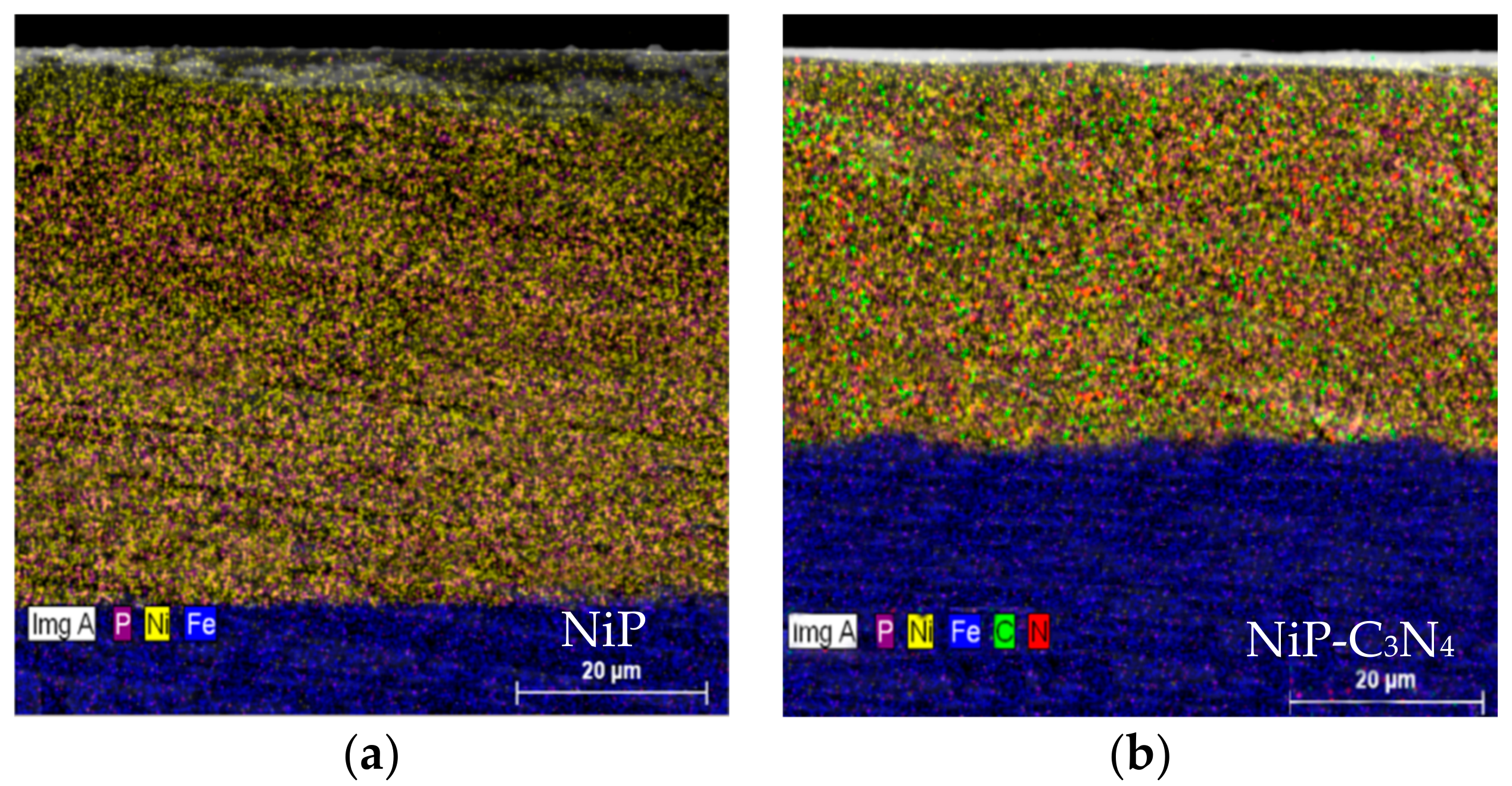
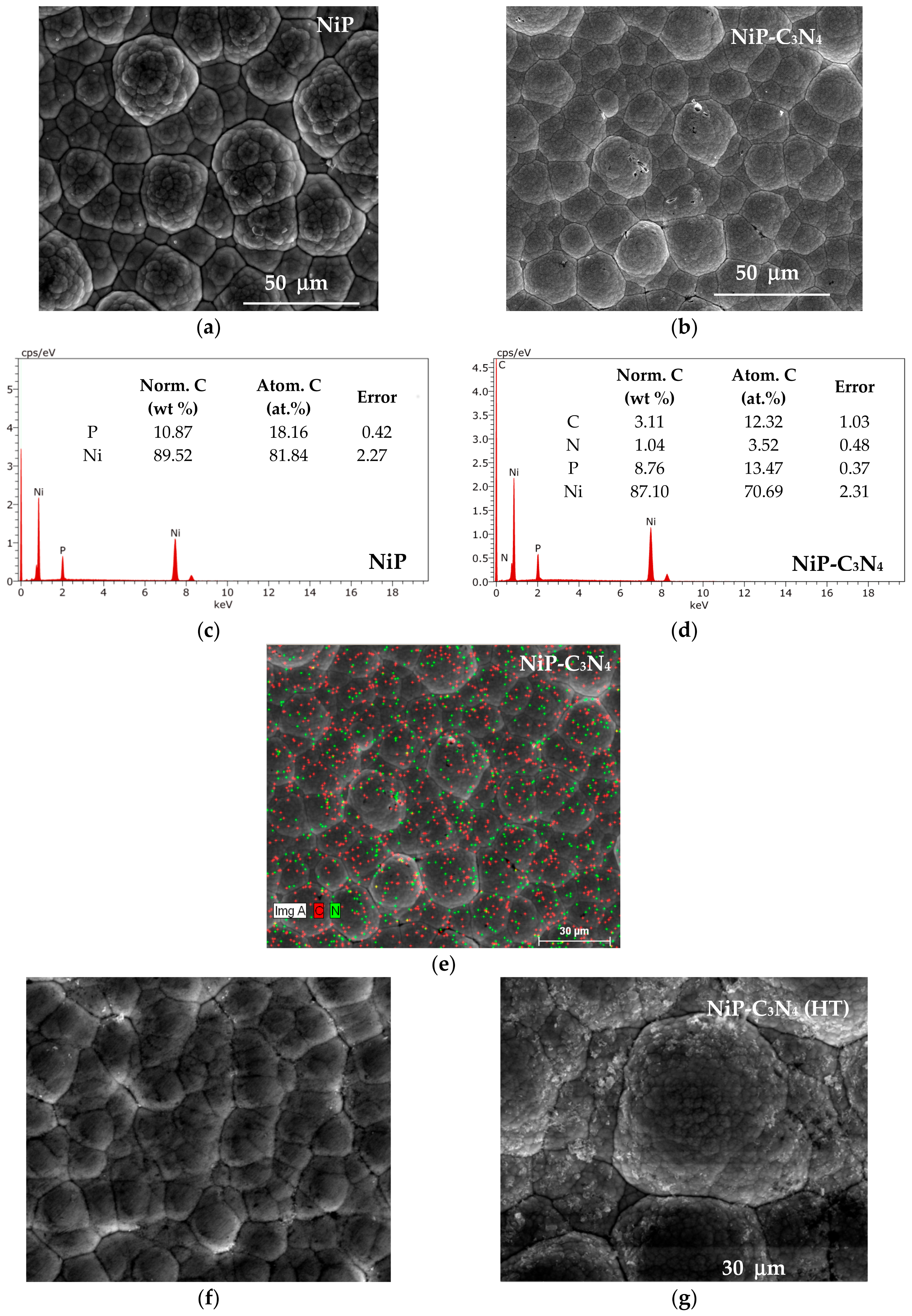
3.1. Surface Morphology of the Ni-P and Ni-P-C3N4 Coatings

The SEM surface morphology of the as-plated NiP and NiP-C3N4 nanocomposite layers are represented in Figure 1a,b, respectively. The surfaces of both coatings exhibit a typical “cauliflower-like” morphology that shows many grains, and each contains many fine granules. Although the cauliflower morphology is a common feature for the electroless-plated NiP alloys, it can be observed that there are spaces between the nodules that facilitate the diffusion of the corrosive media to the substrate, as shown in Figure 1a. Figure 1b reveals a fine microstructure of the NiP-C3N4 nanocomposite coating compared to the NiP coatings that are shown in Figure 1a. This may be attributed to the uniform distribution of the C3N4 nanosheets in the NiP composite coating surface that results in a more fine compact structure with higher surface roughness, as shown later in AFM measurements. Figure 1c,d showed the EDX spectra of the as-plated NiP and NiP-C3N4 coatings that illustrate the presence of nitrogen in the nanocomposite, which proved the successful co-deposition of the C3N4 nanosheets into the NiP matrix. As seen in Figure 1e, for more illustration, the EDX mapping proves that the C3N4 nanosheets are uniformly and homogeneously distributed in the NiP matrix.
Furthermore, examination of Figure 1c,d shows that the NiP and NiP-C3N4 coatings contain approximately 10.48 and 8.76 wt % phosphorus, respectively. According to [23,24], the microstructure of ENP (Electroless NiP) coatings has been reported to be either amorphous or crystalline, or both, depending on the phosphorous content involved. For instance, crystalline, mixed amorphous-crystalline, and amorphous structures have been reported for low (1–5 wt %), medium (6–9 wt %), and high (10–13 wt %) phosphorous ENP coatings, respectively. Therefore, the microstructure of the NiP coating is amorphous (see XRD results in Section 3.3), whereas that of the NiP-C3N4 coating tends to be a mixed crystalline-amorphous, as depicted by XRD results in Section 3.3.
After HT at 400 °C for 1 h, the granular morphology of the as-plated NiP coating is gradually diminished and becomes smoother, as shown in Figure 1f. Comparison of the as-plated NiP-C3N4 composite coating to the heat-treated composite coating reveals that there is a difference in the nodular morphology, and the particles become larger and more agglomerated, as shown in Figure 1g. The change in the morphology with HT may be attributed to the different diffusion coefficients for the different phases in the composite coatings.
The cross-section morphology of as-plated NiP and NiP-C3N4 coatings was checked using SEM, as shown in Figure 2. It was revealed that the thickness of the NiP coating is approximately 52 µm, whereas the NiP-C3N4 coating has a thickness of 35 µm. This indicates that the existence of the reinforcing phase (C3N4) in the coating decreased the thickness considerably. Decreasing the thickness reveals the low deposition rate of the NiP-C3N4 coating compared to that for the NiP one. This may be attributed to the possibility of the physical adsorption of some C3N4 particles on the catalytic surface that result in the minimization of the available active sites for the deposition process that decreases the overall deposition rate [25]. In addition, there are no defects or cracks observed at the substrate-coating interface. This demonstrates the good adhesion of the coatings. The thickness of both coatings does not change after the HT.

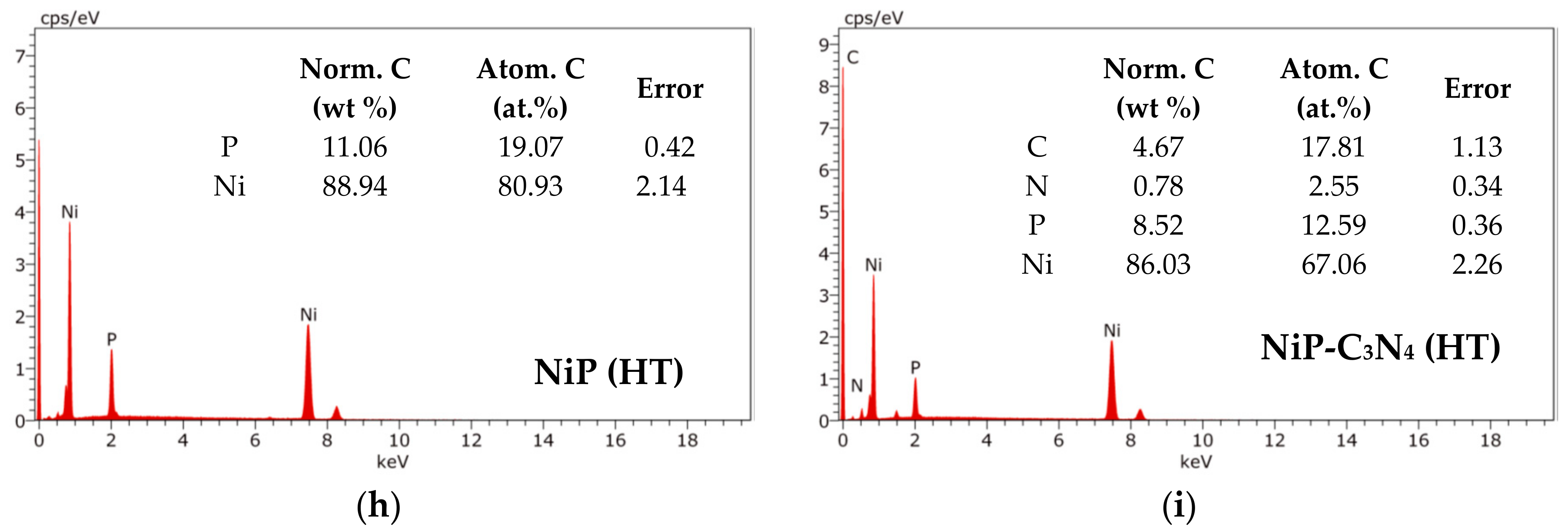
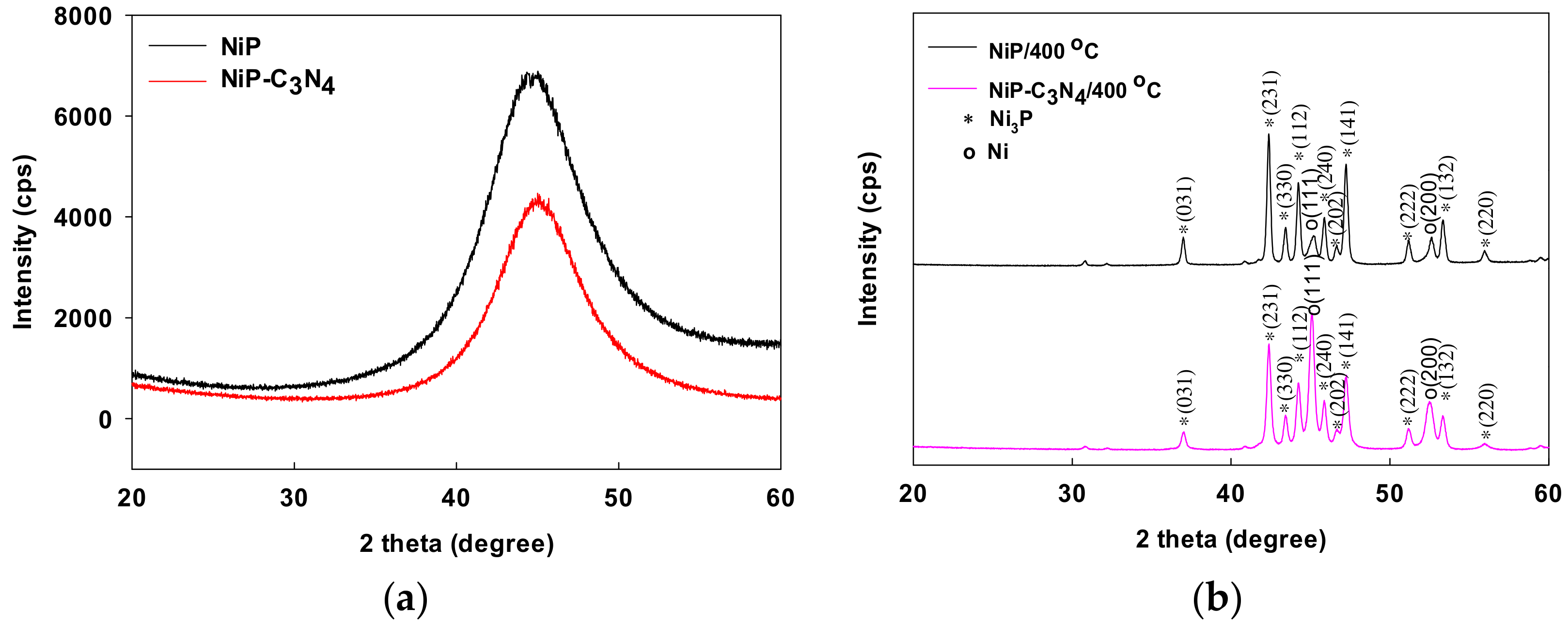
3.2. Structures of the Ni-P and Ni-P-C3N4 Coatings

XRD patterns of both as-plated and heat-treated Ni-P and Ni-P-C3N4 layers are represented in Figure 3a,b, respectively. It is observed that the diffraction pattern of both NiP and NiP-C3N4 composite coatings before the HT has only a single broad peak at 44.5°, which is related to a face-centered cubic (FCC) Ni (111) plane, as shown in Figure 3a. The peaks representing the C3N4 particles that appear in the inset of Figure 3a are not detected in the diffraction pattern of the composite coating shown in Figure 3a. This may be attributed to the low quantity of C3N4 and high density of Ni diffraction peaks. According to the EDX results, the NiP-C3N4 composite coating microstructure is a mixture of amorphous and crystalline phases. Based on the full width at half maximum (FWHM), it is found that the FWHM of the NiP and NiP-C3N4 composite coatings is 7.63 and 6.34, respectively. Therefore, it is concluded that the presence of C3N4 in the coating promotes the formation of crystalline phase; see a similar case in Ref. [26].
After HT, the as-plated NiP coating crystallized mainly as Ni3P particles on the surface. As the amorphous structure is metastable, its peak decreased after HT and crystalline Ni; also, Ni3P phases are formed. It is clear that the diffraction pattern of the C3N4 nanocomposite coating coincides with that of the NiP coating, i.e., the presence of C3N4 nanosheets in the coating has not affected the phase angle (peaks positions) of the coating, and new peaks have not appeared. Moreover, it can be observed that the intensity of the resulted peaks decreases dramatically for the NiP-C3N4 nanocomposite coating compared to C3N4-free one. This can explained by the decrease in the amount of deposited Ni and P as a result of presence of C3N4 in the coating. This is illustrated in the EDX charts shown above in Figure 1h,i, in which the Ni and P contents decreased by 3.2 wt % and 22.9 wt %, respectively. In addition, as illustrated in Figure 1h, increasing the P(wt %) in the heat-treated NiP coating results in smaller Ni diffraction peaks.

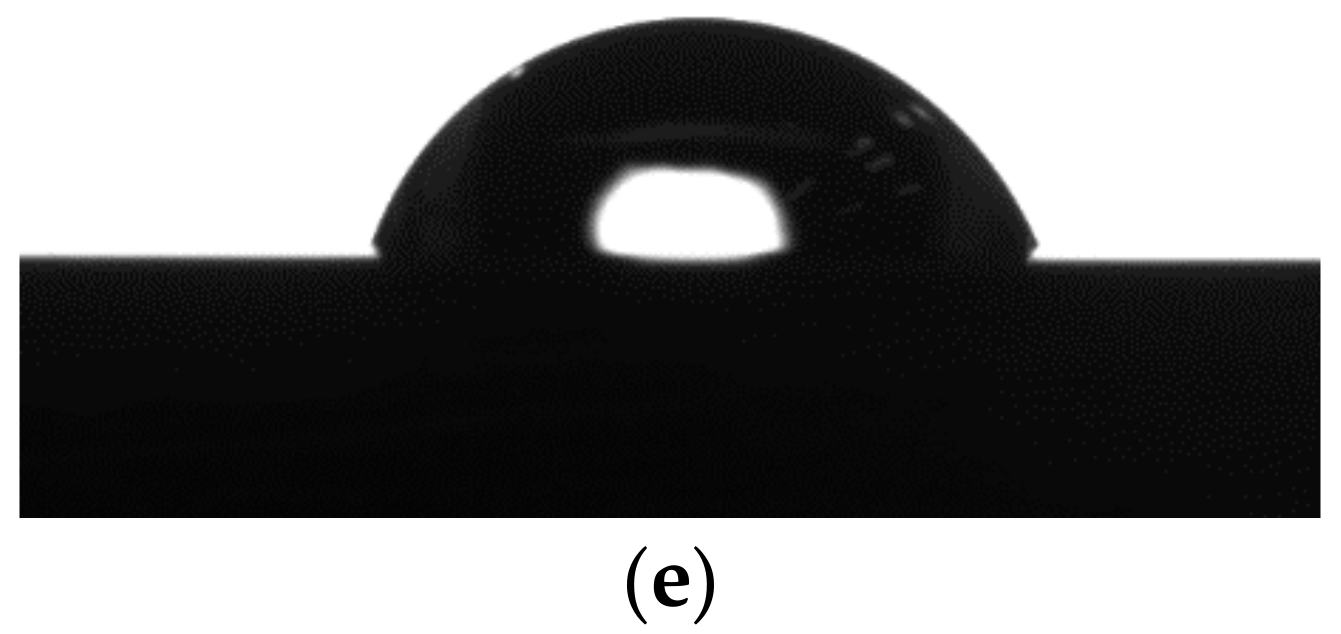
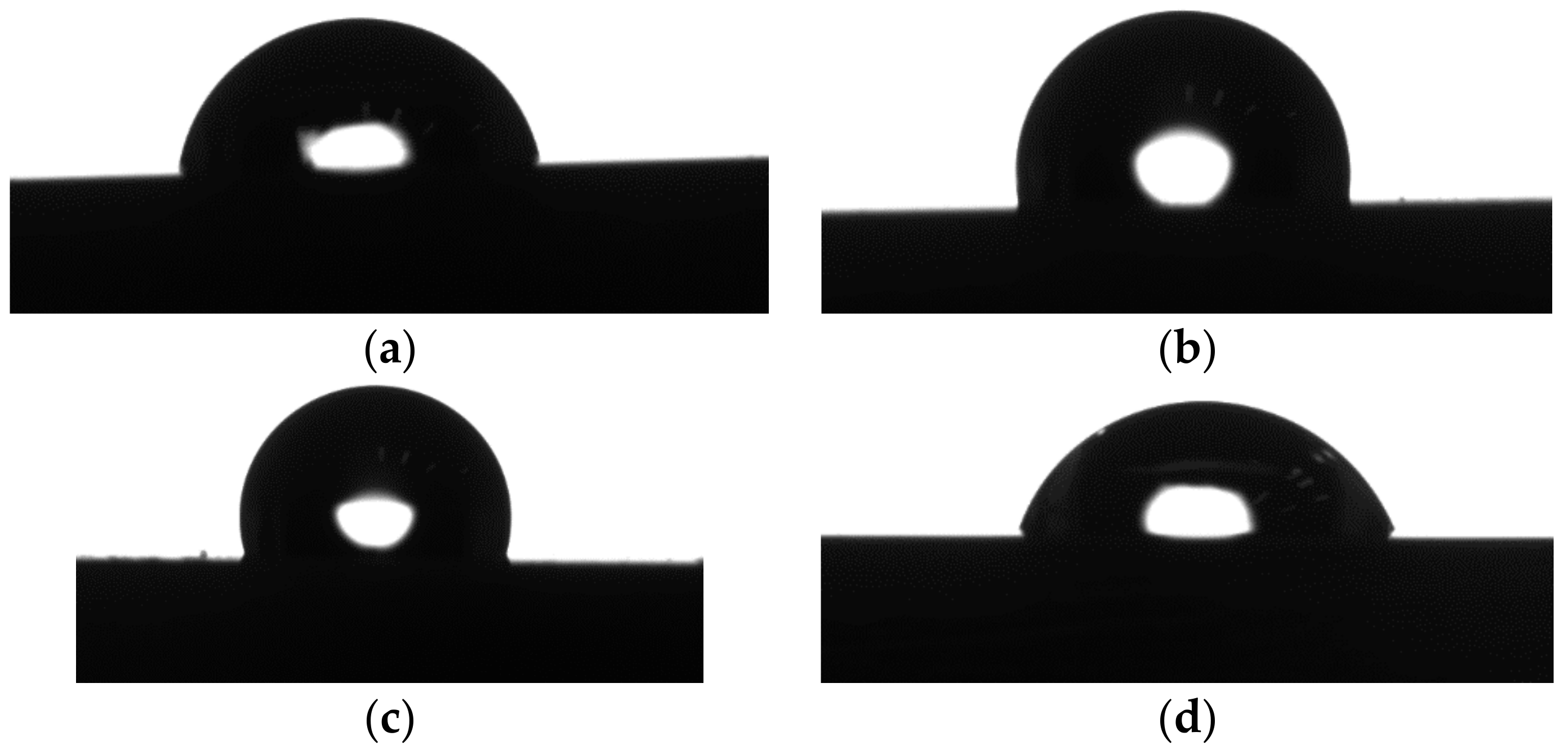
3.3. Contact Angle Measurements

The surface roughness of coatings, in addition to its directly related properties, e.g., hydrophilicity and hydrophobicity, are important properties to be studied. The higher the surface roughness is, the more hydrophobic and corrosion-resistant the coating will be. Figure 4 shows the water contact angles (WCAs) of the substrate (API X120 steel), the NiP, and the NiP-C3N4 nanocomposite coatings before and after the HT at 400 °C for 1 h.
The WCA for steel is 86°, i.e., less than 90°, indicating its hydrophilic nature. Both as-plated NiP and NiP-C3N4 coatings are hydrophobic, as their contact angles are found to be 105° and 109°, respectively. After HT, a decrease in the water contact angle is observed for both NiP and the nanocomposite coatings (Figure 4d,e). Because of the recrystallization of the nickel and a phase transition that led to the change in the surface chemistry and roughness of the NiP coatings, the as-plated coatings became hydrophilic after HT [27].

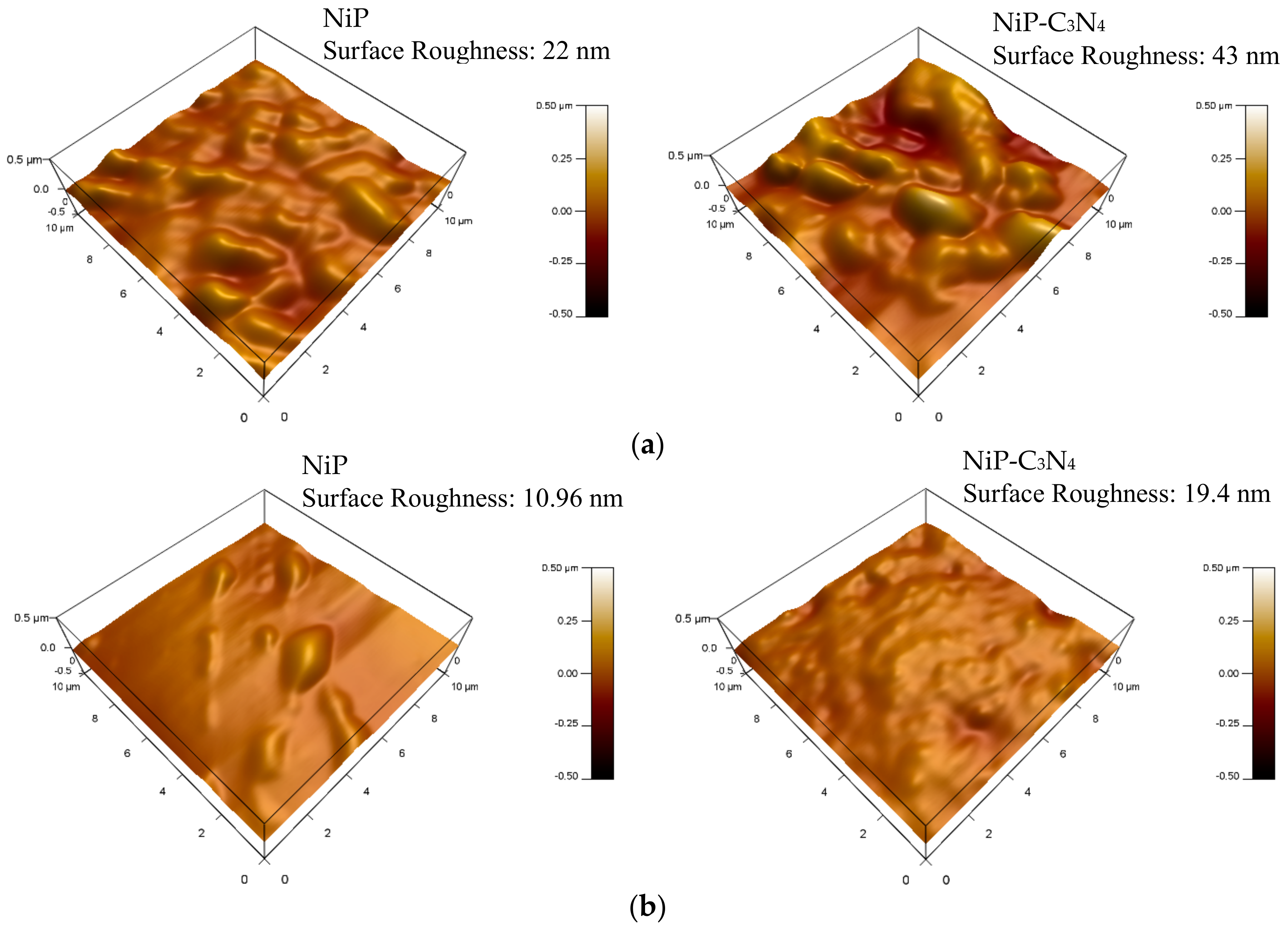
3.4. Surface Roughness of Coatings

The Atomic force microscopy (AFM) was used to measure the surface roughness of the NiP and NiP-C3N4 coatings before and after the heat treatment, as shown in Figure 5. The surface roughness of the NiP-C3N4 composite coating in the presence of C3N4 nanosheets in the NiP coating increased. The surface roughness of the as-plated NiP coating is 22 nm, whereas the NiP-C3N4 shows a surface roughness of approximately 43 nm. This proves the increased hydrophobicity of the NiP-C3N4 coating relative to that of the NiP coating. It is obvious that the surface roughness of the NiP coating and the C3N4 composite coating after the heat treatment decreased by about half of their initial values. This was attributed to the recrystallization of the coatings and the formation of the Ni3P and Ni crystals that are more stable and show ordered structures. Therefore, the roughness of the NiP-C3N4 composite coating is always higher than that of the NiP coating, even after reduction of the roughness upon the heat treatment.

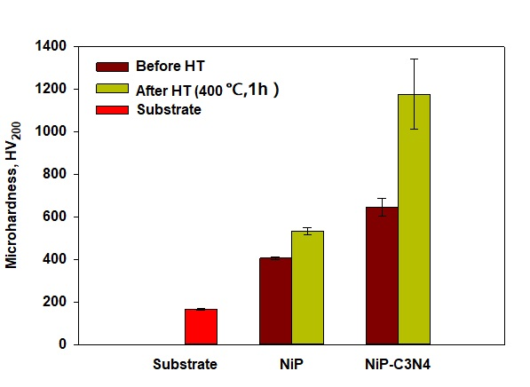
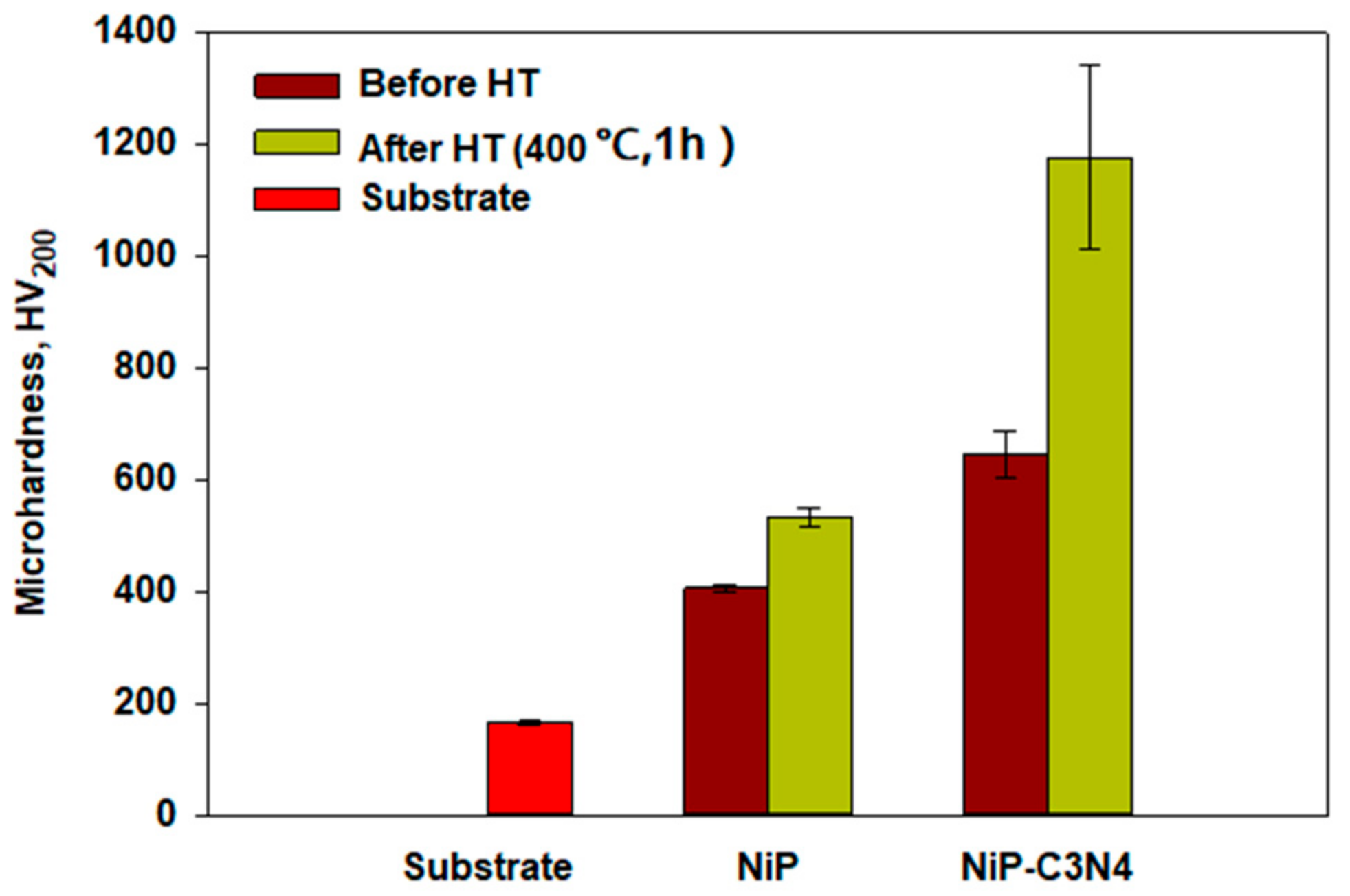
3.5. Microhardness Measurements

The microhardness of the NiP and NiP nanocomposite coatings before and after the heat treatment were performed in addition to that of the C-steel substrate for comparison, as illustrated in Figure 6. The measured microhardness of the substrate is approximately 166 HV200. The electroless deposition of the NiP and NiP-C3N4 leads to an increase in the microhardness to 406 and 645 HV200, respectively. The increase in the microhardness upon the dispersion of the C3N4 nanosheets is attributed to the dispersion hardening effect caused via the incorporation of the nanoparticles into the composite coatings. As reported in [28,29], the uniform distribution of the nanoparticles in the matrix could restrain the growth of the alloy grains and the plastic deformation of the coating, leading to the stabilization of the dislocation and thus increasing the microhardness.
Upon heat treatment of NiP and NiP-C3N4 nanocomposites, the microhardness was increased significantly to 780 and 1175 HV200, respectively. At that temperature (400 °C), the P atoms are forced to adapt to the crystal structure of the Ni. This adaptation resulted in the formation of a coherent relationship that leads to a distortion of the local stress field. When the Ni/P ratio gathers in a sufficient quantity, the intermetallic compound Ni3P precipitates and keeps a coherent relationship with the Ni. The hardness of the Ni3P is gets higher when the temperature is increased, since it is formed mainly by metallic and ionic bonds, resulting in a coherent precipitation strengthening effect and an improvement of the microhardness [30]. Regarding the NiP-C3N4 composite, the presence of Ni3P as the hard phase in addition to the C3N4 provides an extra factor for increasing its microhardness after the heat treatment. Although the intensity of the Ni3P peaks in the NiP-C3N4 XRD chart is lower than the corresponding ones in the XRD chart of the C3N4—free coating, the hardness is higher in the case of NiP-C3N4 coating, indicating that the C3N4 compensated for the decrease in the Ni3P content, which is an advantage for the new coating. In addition, it worth mentioning that the thickness of the coating in case of the NiP-C3N4 coating is 30% less than that in case of the NiP one.

3.6. Corrosion Measurements

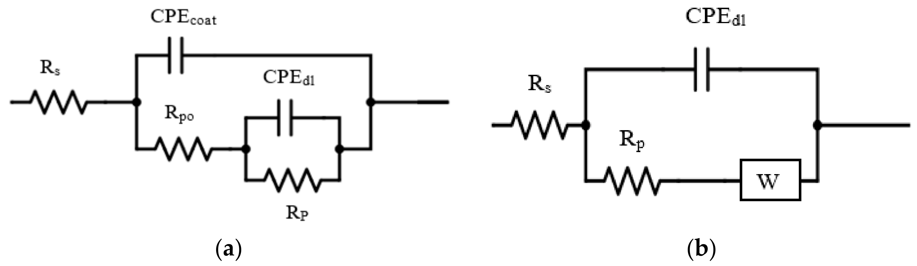
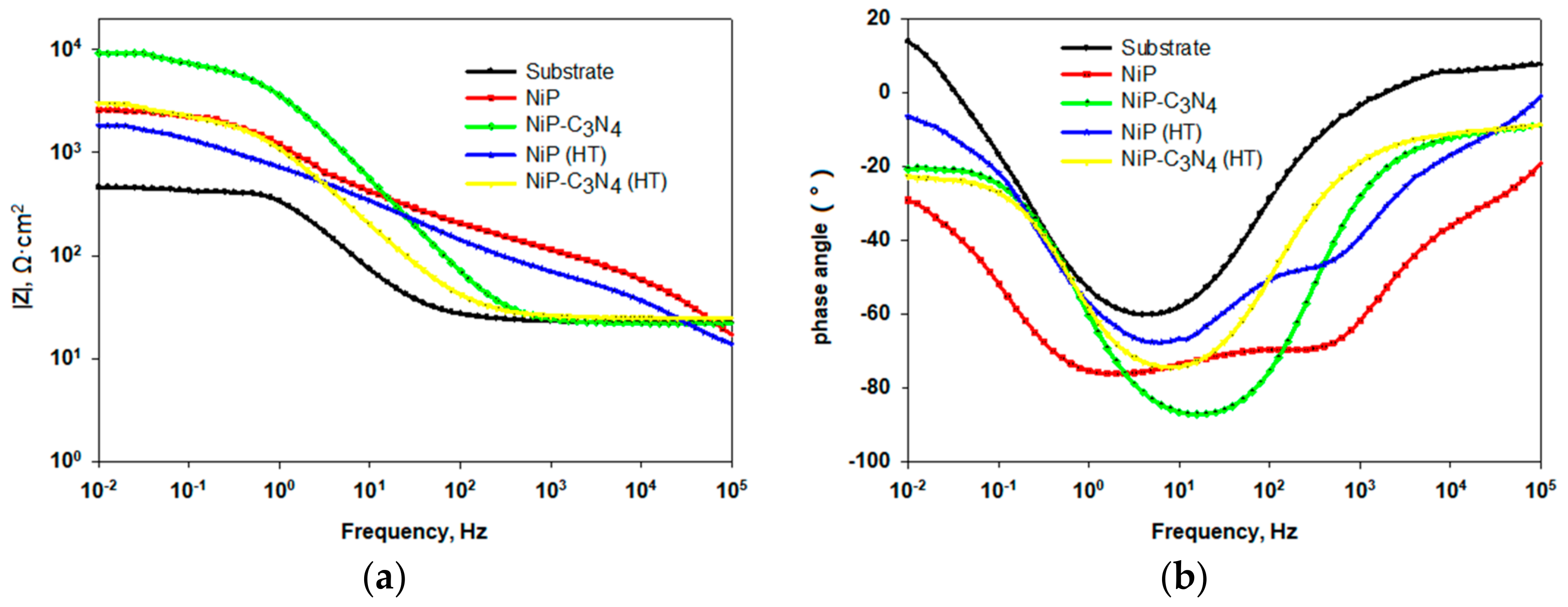
3.6.1. Electrochemical Impedance Spectroscopy (EIS)

Figure 7a,b show the Bode and the phase angle plots of the EIS spectra that are measured at open circuit potential for the substrate with the as-plated and heat-treated NiP, as well as NiP-C3N4 nanocomposite coatings immersed in a 3.5 wt % NaCl solution at the room temperature. The larger the value of the |Z| at low frequencies is, the better the corrosion protection properties of the coating will be [31]. Inspection of Figure 7a shows that the values of |Z| at 0.01 Hz for the as-plated NiP and NiP-C3N4 nanocomposite coatings, as well as for the heat-treated coatings, are much higher than that of the substrate, confirming the corrosion protection properties of both coatings before and after the heat treatment. The high corrosion resistance is attributed to the presence of phosphorus [32]. Generally, for a Ni-based coating, when the nickel starts to dissolve in the corrosive media, the phosphorus starts to react with water to form a film of adsorbed hypophosphite anions, preventing further hydration of the nickel. Consequently, the corrosion resistance of the coating is increased [33]. Moreover, the as-plated NiP-C3N4 composite coating offers higher corrosion protection ability compared to that of the as-plated NiP coating despite the smaller phosphorous content in the former, as seen from the EDX results. This finding indicates the strong protective ability of the C3N4 nanosheets that enhance the polarization resistance of the NiP nanocomposite coating in 3.5 wt % NaCl solution to reach a maximum value of 9225 Ω·cm2, as shown in Table 2. This can be attributed, as mentioned above, to the uniform distribution of C3N4 nanosheets throughout the coating, which support forming a more compact structure, blocking the defects in the NiP coating, inhibiting the diffusion of the chloride ions to the substrate, and enhancing the corrosion resistance as shown in a similar situation in [10].
In addition, in Figure 7a, the Bode plots of the as-plated NiP and NiP-C3N4 nanocomposite coatings display different shapes in the recorded frequency regions, illustrating that different fundamental processes occur on their surfaces. This behavior is more conspicuous in the plots of the phase angle versus frequency (Figure 7b). The Bode and phase angle plots for the NiP coating show two broad peaks at the analyzed frequency range, which confirms two-time constants behavior. The first relaxation process is related to the coating layer that can be checked at the higher and intermediate frequencies, whereas the second relaxation process is observed at the lower frequencies and represents the electrochemical behavior at the interface of the substrate and the coating [34]. The Bode and phase angle plots for the NiP-C3N4 nanocomposite coating show one time-constant behavior, as shown in Figure 7b.
The equivalent circuits that are used in analyzing the EIS measured spectra for both the as-plated NiP and NiP-C3N4 coatings with and without heat treatment are depicted in Figure 8a,b, respectively. The circuit in Figure 8a includes the solution resistance (Rs), the high frequency time constant (R1·CPE1), and the low frequency time constant (R2·CPE2). The high frequency time constant (R1·CPE1) corresponds to the areas covered with the coating and can be represented by the coating admittance (CPEcoat) and the pore resistance (Rpo). The low frequency time constant is assigned to the polarization resistance (Rp) and the admittance associated with the double layer capacitance (CPEdl). The equivalent circuit in Figure 8b consists of the solution resistance, the double layer capacity, the polarization resistance, and the Warburg diffusion element (W). The electrochemical parameters derived from fitting the measured data using the equivalent circuits are listed in Table 2. As is clearly shown in this table, the increased polarization resistance is related to the presence of the C3N4 nanosheets. Moreover, the NiP-C3N4 composite coating has the lowest double layer capacitance (39 µF·cm−2·sn) and the higher value of n (0.9) compared to those of the NiP coating. Taken together, these characteristics lead to the superior protection efficiency of the composite coating reaching as high as 95%. The protection efficiency of the NiP coating is approximately 70.9%, which is less than that of the composite due to its porosity, which allows the aggressive chloride ions to diffuse into the substrate.
After heat treatment, the polarization resistances of both heat-treated NiP and NiP-C3N4 are decreased compared to the corresponding polarization resistances for the as-plated coatings, but are still much greater than that of the substrate. The protective ability of the as-plated NiP and NiP-C3N4 composite coatings decreases after the heat treatment by approximately 11% and 9.5%, respectively, as shown in Table 2. However, the protection efficiency of the heat-treated NiP-C3N4 composite coating is still higher by 13% and 4% than that of the heat-treated and as-plated NiP coatings, respectively. The decrease in the corrosion protection observed for both heat-treated coatings is due to the formation of nickel phosphide (Ni3P) that reduces the phosphorus content of the remaining material and transforms the coating from amorphous to crystalline. Previous work has shown that the amorphous alloys have better corrosion resistance than their corresponding crystalline due to the formation of glassy films that passivate their surfaces [33].
The n values for both NiP and NiP-C3N4 coatings before and after the heat treatment lie between 0.6 and 0.9 (Table 2). This indicates that the system is far from the ideal capacitive behavior. The deviation from the ideal capacitive behavior is related to the inhomogeneity of the coating surface attributed to the roughness and surface porosity of the coating. According to the obtained values of the CPEdl presented in Table 2, the NiP-C3N4 composite coating before and after the heat treatment has the most homogeneous surface with a lower porosity compared to that of the NiP coating. Consequently, a dense NiP-C3N4 composite coating is formed on the substrate that is slightly affected by high temperatures.

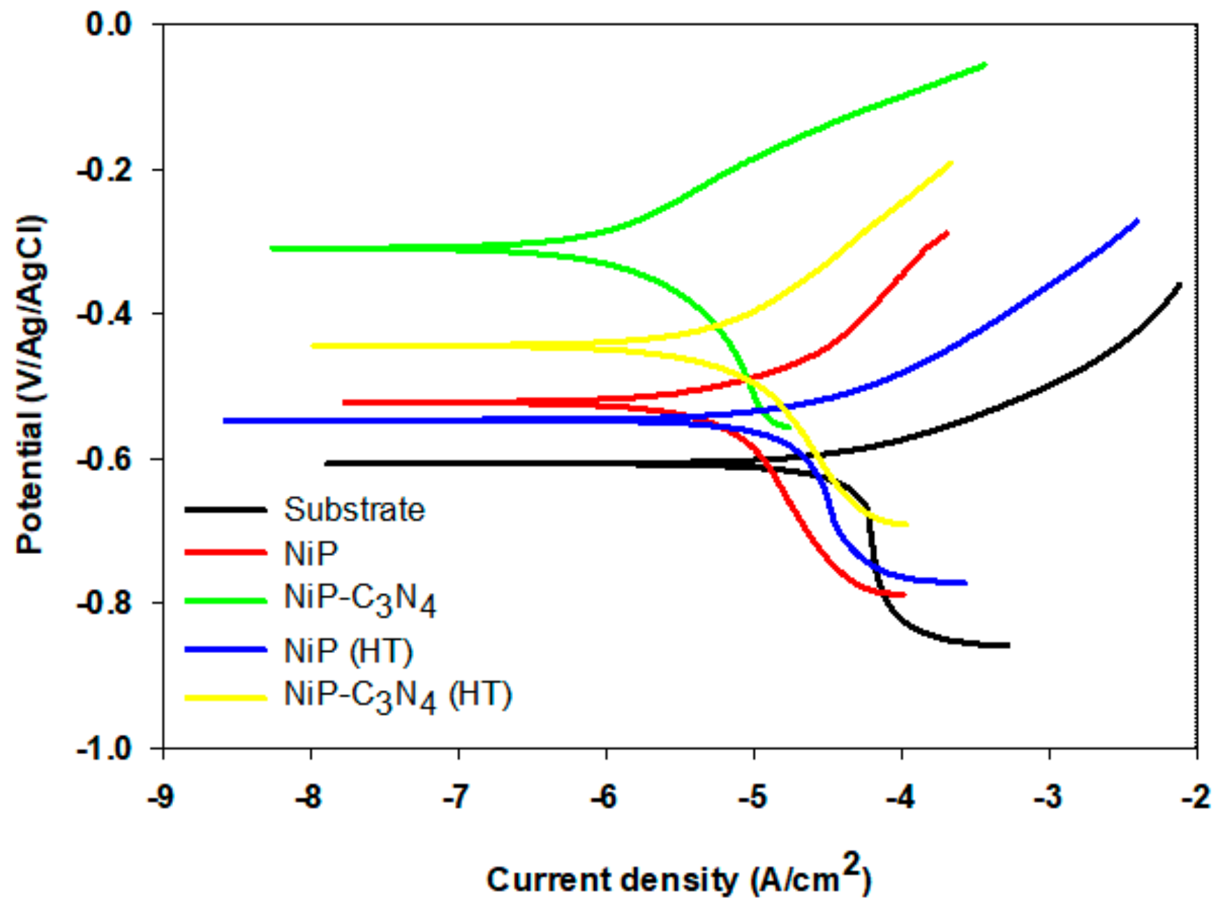
3.6.2. Tafel Analysis

The potentiodynamic polarization curves for the substrate and electroless NiP, as well as NiP-C3N4 coatings before and after the heat treatment in 3.5 wt % NaCl solution at room temperature, are shown in Figure 9. The electrochemical parameters (corrosion potential (Ecorr), corrosion current density (icorr), cathodic and anodic Tafel slopes, and corrosion inhibition efficiency IE) are presented in Table 3. Ecorr of the NiP coating (−542 mV) is shifted significantly in the anodic direction compared to the C-steel, and that of the NiP-C3N4 is even more anodically shifted to −309 mV. icorr of the substrate, NiP, and NiP-C3N4 composite coatings are 21.4, 6.9, and 1.8 µA·cm−2, respectively. The decrease in the icorr of the NiP-C3N4 composite coating compared to that of the NiP coating reveals a better corrosion resistance for the new composite coating. After heat treatment, Ecorr of the NiP and the NiP-C3N4 composite coatings are shifted in the cathodic direction. In addition, the icorr values of the NiP and NiP-C3N4 coatings are slightly increased compared to those before the heat treatment. This is due to the formation of crystalline Ni3P. Consequently, an increase in icorr results in a decrease in the IE to 60% and 82% for the heat-treated NiP and NiP-C3N4 coatings, respectively. It is worth mentioning that the IE of the heat-treated NiP-C3N4 composite coating is still higher than those of the NiP coating before and after the heat treatment. This is attributed to the existence of C3N4, which enhances the corrosion resistance by forming a more compact composite structure via uniform dispersion into the NiP matrix (confirmed by EDX mapping) and blocking the defects in the NiP coating [29].

4. Conclusions

The electroless deposition of the NiP-C3N4 nanocomposite coating is successfully achieved by sonicating the C3N4 nanosheets in the electroless NiP bath under the same conditions used for NiP electroless deposition. The morphology, structure, roughness, wettability, hardness, and corrosion resistance of the novel electroless NiP-C3N4 nanocomposite coating in comparison with the conventional NiP coating before and after heat treatment show superior properties of the new nanocomposite compared to the NiP alloy. The structure of the as-deposited NiP coating is amorphous, whereas that of the as-deposited NiP-C3N4 composite coating is crystalline-amorphous. The microstructure of the NiP coating is affected by the existence of the C3N4 nanosheets, which are uniformly spread within the NiP matrix. The existence of the C3N4 nanosheets and the heat treatment significantly enhances the microhardness of the NiP coating. The orderly presence of the C3N4 nanosheets in the coating led to the increase in the protection efficiency of the as-plated composite coating in a 3.5 wt % NaCl solution to 95% based on EIS results. After heat treatment, the formation of the crystalline Ni3P phase slightly decreased the corrosion resistance of both the NiP and NiP-C3N4 nanocomposite coatings. However, the NiP-C3N4 nanocomposite still shows a corrosion protection efficiency that is higher than that of the NiP even before heat treatment.

Acknowledgments

This work was supported by the NPRP grant # NPRP8-1212-2-499 from the Qatar National Research Fund (a member of Qatar Foundation). The statements made herein are solely the responsibility of the authors.

Author Contributions

E.F., A.A. and M.H. conceived and designed the experiments; E.F. performed the experiments; E.F. and A.A. analyzed the data; C.W., G.J. and Z.F. contributed materials and revised the paper; E.F. wrote the first draft of the manuscript and A.A., M.H. and A.M. revised the paper.

Conflicts of Interest

The authors declare no conflict of interest.

References

  1. HariKrishnan, K.; John, S.; Srinivasan, K.N.; Praveen, J.; Ganesan, M.; Kavimani, P.M. An overall aspect of electroless Ni-P depositions—A review article. Metall. Mater. Trans. A 2006, 37, 1917–1926. [Google Scholar] [CrossRef]
  2. Balaraju, J.N.; Narayana, T.S.N.S.; Seshadri, S.K. Electroless Ni-P composite coatings. J. Appl. Electrochem. 2003, 33, 807–816. [Google Scholar] [CrossRef]
  3. Agarwala, R.C.; Agarwala, V.; Sharma, R. Electroless Ni-P based nano coating technology—A review. Synth. React. Inorg. Met.-Org. Chem. 2006, 36, 493–515. [Google Scholar] [CrossRef]
  4. Makkar, P.; Agarwala, R.C.; Agarwala, V. Studies on electroless coatings at IIT Roorkee—A brief review. Mater. Sci. Forum 2013, 33, 275–288. [Google Scholar] [CrossRef]
  5. Sahoo, P.; Das, S.K. Tribology of electroless nickel coatings—A review. Mater. Des. 2011, 32, 1760–1775. [Google Scholar] [CrossRef]
  6. Sharma, S.B.; Agarwala, R.C.; Agarwala, V.; Ray, S. Dry sliding wear and friction behavior of Ni-P-ZrO2-Al2O3 composite electroless coatings on aluminium. Mater. Manuf. Processes 2002, 17, 637–649. [Google Scholar] [CrossRef]
  7. Srinivasan, K.N.; Thangavelu, P. Electroless deposition of Ni-P composite coatings containing kaolin nanoparticles. Trans. Inst. Met. Finish. 2012, 90, 105–112. [Google Scholar] [CrossRef]
  8. Hu, J.; Fang, L.; Zhong, P. Effect of Reinforcement Particle Size on Fabrication and Properties of Composite Coatings. Mater. Manuf. Processes 2013, 28, 1294–1300. [Google Scholar] [CrossRef]
  9. Sharma, A.; Singh, A.K. Electroless Ni-P and Ni-P-Al2O3 Nanocomposite Coatings and Their Corrosion and Wear Resistance. J. Mater. Eng. Perform. 2013, 22, 176–183. [Google Scholar] [CrossRef]
  10. Zhou, H.-M.; Jia, Y.; Li, J.; Yao, S.-H. Corrosion and wear resistance behaviors of electroless Ni-Cu-P-TiN composite coating. Rare Met. 2016, 1–6. [Google Scholar] [CrossRef]
  11. Rezagholizadeh, M.; Ghaderi, M.; Heidary, A.; Vaghefi, S.M.M. Electroless Ni-P/Ni-B-B4C duplex composite coatings for improving the corrosion and tribological behavior of Ck45 steel. Prot. Met. Phys. Chem. Surf. 2015, 51, 234–239. [Google Scholar] [CrossRef]
  12. Yang, Y.; Chen, W.; Zhou, C.; Xu, H.; Gao, W. Fabrication and characterization of electroless Ni-P-ZrO2 nano-composite coatings. Appl. Nanosci. 2011, 1, 19–26. [Google Scholar] [CrossRef]
  13. Soleimani, R.; Mahboubi, F.; Kazemi, M.; Arman, S.Y. Corrosion and tribological behaviour of electroless Ni-P/nano-SiC composite coating on aluminium 6061. Surf. Eng. 2015, 31, 714–721. [Google Scholar] [CrossRef]
  14. Novakovic, J.; Vassiliou, P.; Samara, K.; Argyropoulos, T. Electroless Ni-P-TiO2 composite coatings: Their production and properties. Surf. Coat. Technol. 2004, 201, 895–901. [Google Scholar] [CrossRef]
  15. Xu, S.; Hu, X.; Yang, Y.; Chen, Z.; Chan, Y.C. Effect of carbon nanotubes and their dispersion on electroless Ni-P under bump metallization for lead-free solder interconnection. J. Mater. Sci. Mater. Electron. 2014, 25, 2682–2691. [Google Scholar] [CrossRef]
  16. Liu, S.; Bian, X.; Liu, J.; Yang, C.; Zhao, X.; Fan, J.; Zhang, K.; Bai, Y.; Xu, H.; Liu, Y. Structure and properties of Ni-P-graphite (Cg)-TiO2 composite coating. Surf. Eng. 2015, 31, 420–426. [Google Scholar] [CrossRef]
  17. Ashassi-Sorkhabi, H.; Es’haghi, M. Corrosion resistance enhancement of electroless Ni-P coating by incorporation of ultrasonically dispersed diamond nanoparticles. Corros. Sci. 2013, 77, 185–193. [Google Scholar] [CrossRef]
  18. Liu, A.Y.; Cohen, M.L. Prediction of new low compressibility solids. Science 1989, 245, 841. [Google Scholar] [CrossRef] [PubMed]
  19. Liu, A.Y.; Cohen, M.L. Structural properties and electronic structure of low-compressibility materials: β-Si3N4 and hypothetical β-C3N4. Phys. Rev. B 1990, 41, 10727. [Google Scholar] [CrossRef]
  20. Zhang, Z.; Guo, H.; Xu, Y.; Zhang, W.; Fan, X. Corrosion resistance studies on α-C3N4 thin films deposited on pure iron by plasma-enhanced chemical vapor deposition. J. Mater. Sci. Lett. 1999, 18, 685–687. [Google Scholar] [CrossRef]
  21. Xu, H.; Yanga, Z.; Li, M.K.; Shi, Y.L.; Huang, Y.; Li, H.L. Synthesis and properties of electroless Ni-P-nanometer diamond composite coatings. Surf. Coat. Technol. 2005, 191, 161–165. [Google Scholar] [CrossRef]
  22. Al-Kandari, H.; Abdullah, A.M.; Ahmad, Y.H.; Al-Kandari, S.; AlQaradawi, S.Y.; Mohamed, A.M. An efficient eco advanced oxidation process for phenol mineralization using a 2D/3D nanocomposite photocatalyst and visible light irradiations. Sci. Rep. 2017, 7, 9898. [Google Scholar] [CrossRef] [PubMed]
  23. Sudagar, J.; Lian, J.; Sha, W. Electroless nickel, alloy, composite and nano coatings—A critical review. J. Alloy. Compd. 2013, 571, 183–204. [Google Scholar] [CrossRef] [Green Version]
  24. Rajabalizadeh, Z.; Seifzadeh, D. The effect of copper ion on microstructure, plating rate and anticorrosive performance of electroless Ni-P coating on AZ61 magnesium alloy. Prot. Met. Phys. Chem. Surf. 2014, 50, 516–523. [Google Scholar] [CrossRef]
  25. Afroukhteh, S.; Dehghaniann, C.; Emamy, M. Preparation of electroless Ni-P composite coatings containing nano-scattered alumina in presence of polymeric surfactant. Prog. Nat. Sci. Mater. Int. 2012, 22, 318–325. [Google Scholar] [CrossRef]
  26. Zou, Y.; Cheng, Y.; Cheng, L.; Liu, W. Effect of Tin Addition on the Properties of Electroless Ni-P-Sn Ternary Deposits. Mater. Trans. 2010, 51, 277–281. [Google Scholar] [CrossRef]
  27. Karthikeyan, S.; Vijayaraghavan, L. Investigation of the surface properties of heat-treated electroless Ni-P coating. Trans. IMF 2016, 94, 265–273. [Google Scholar] [CrossRef]
  28. Balaraju, J.N.; Kalavati; Rajam, K.S. Influence of particle size on the microstructure, hardness and corrosion resistance of electroless Ni-P-Al2O3 composite coatings. Surf. Coat. Technol. 2006, 200, 3933–3941. [Google Scholar] [CrossRef]
  29. Aal, A.A.; El-Sheikh, S.M.; Ahmed, Y.M.Z. Electrodeposited composite coatings of Ni-W-P with nano-sized rod and spherical-shaped SiC particles. Mater. Res. Bull. 2009, 44, 151–159. [Google Scholar] [CrossRef]
  30. Liu, B.; Liu, L.; Liu, X. Effects of carbon nanotubes on hardness and internal stress in Ni-P coatings. Surf. Eng. 2013, 29, 507–510. [Google Scholar] [CrossRef]
  31. Sharma, S.K. Green Corrosion Chemistry and Engineering; Wiley-VCH: Weinheim, Germany, 2012. [Google Scholar]
  32. MafiIman, R.; Dehghanian, C. Studying the effect of the addition of TiN nanoparticles to NiP electroless coatings. Appl. Surf. Sci. 2011, 258, 1876–1880. [Google Scholar]
  33. Hu, J.; Fang, L.; Liao, X.-L.; Shi, L.-T. Influences of different reinforcement particles on performances of electroless composites. Surf. Eng. 2017, 33, 362–386. [Google Scholar] [CrossRef]
  34. Balaraju, J.N.; EzhilSelvi, V.; Rajam, K.S. Elactrochemical behavior of low phosphorous electroless Ni-P-Si3N4 composite coatings. Mater. Chem. Phys. 2010, 120, 546–551. [Google Scholar] [CrossRef]
Figure 1. (a,b,f,g) SEM micrographs and (c,d,h,i) EDX elemental analysis of the electroless as-plated (a,c) NiP, (b,d) as-plated NiP-C3N4, (f,h) heat-treated NiP, and (g,i) heat-treated NiP-C3N4, respectively; (e) EDX mapping for the C and N elements on the surface of the NiP-C3N4 composite coating.
Coatings 08 00037 g001aCoatings 08 00037 g001b
Figure 2. The cross-sectional SEM-photomicrographs of the (a) Ni-P and (b) NiP-C3N4 nanocomposite coatings.
Coatings 08 00037 g002
Figure 3. XRD pattern of NiP and NiP-C3N4 coatings (a) before and (b) after HT at 400 °C for 1 h.
Coatings 08 00037 g003
Figure 4. WCAs of coatings: (a) substrate: CA = 86 ± 1°; (b) as-plated NiP: CA = 105 ± 1°; (c) as-plated NiP-C3N4: CA = 109 ± 1°; (d) heat-treated NiP: CA = 70.5 ± 1°; and (e) heat-treated NiP-C3N4: CA = 72.8 ± 1°. Heat treatment was done at T = 400 °C for 1 h.
Coatings 08 00037 g004aCoatings 08 00037 g004b
Figure 5. AFM images of electroless NiP and NiP-C3N4 nanocomposite coatings (a) before and (b) after heat treatment at 400 °C for 1 h.
Coatings 08 00037 g005
Figure 6. The microhardness of substrate, NiP coating, and NiP-C3N4 composite coating before and after heat treatment at 400 °C for 1 h.
Coatings 08 00037 g006
Figure 7. (a) Bode and (b) phase angle plots of the substrate, electroless as-plated NiP and NiP-C3N4 coatings with and without heat treatment at 400 °C for 1 h in 3.5 wt % NaCl solution at room temperature.
Coatings 08 00037 g007
Figure 8. Equivalent electric circuits for (a) as-plated and heat-treated NiP coating and (b) as-plated and heat-treated NiP-C3N4 composite coating, in 3.5 wt % NaCl solution.
Coatings 08 00037 g008
Figure 9. Polarization curves for the substrate, electroless NiP, and NiP-C3N4 deposits, with and without heat treatment in 3.5 wt % NaCl solution at room temperature. The scan rate is 0.167 mV·s−1.
Coatings 08 00037 g009
Table 1. The chemical composition (in wt %) of the substrate.
CSiMnNiCrMoCuVFe
0.1290.1010.5410.0170.0390.00130.0150.25balance
Table 2. Electrochemical parameters obtained by fitting the measured data shown in Figure 7 using the equivalent circuits shown in Figure 8 of the substrate, NiP, and NiP-C3N4 composite coatings with and without heat treatment.
Type of CoatingRs (Ω·cm2)Rpo (Ω·cm2)CPEcoat (µF·cm−2·sn)Rp (Ω·cm2)CPEdl (µF·cm−2·sn)W (S·s1/2)nIE (%)
Substrate22.4445526.5
NiP17.6167.5028.423362940.781
NiP-C3N421.99225391.021 × 10−30.995
NiP(HT)15.616.9351597324.60.6572
NiP-C3N4(HT)23.42990170.003.879 × 10−30.885
Table 3. Electrochemical parameters of different coatings before and after heat treatment derived from polarization curves shown in Figure 9.
Type of CoatingEcorr (mV)icorr (µA·cm−2)ba (V/decade)bc (V/decade)Corrosion Rate (mpy)IE (%)
Substrate−60721.40.10.173.55
NiP−5426.90.090.152.9171.4
NiP-C3N4−3091.80.150.121.491.5
NiP(HT)−5468.40.040.116.560.4
NiP-C3N4(HT)−4443.80.110.122.2682

