Effect of Tip Shape of Frictional Stir Burnishing Tool on Processed Layer’s Hardness, Residual Stress and Surface Roughness


1
Industrial Division, Nikkiso Co., Ltd., 2-16-2 Noguchicho, Higashimurayama-shi, Tokyo 189-8520, Japan
2
Department of Mechanical Systems Engineering, Faculty of Engineering, Tokyo University of Agriculture and Technology, 2-24-16 Nakacho, Koganei-shi, Tokyo 184-8588, Japan
*
Author to whom correspondence should be addressed.
Coatings 2018, 8(1), 32; https://doi.org/10.3390/coatings8010032
Submission received: 30 November 2017
/
Revised: 3 January 2018
/
Accepted: 9 January 2018
/
Published: 11 January 2018
(This article belongs to the Special Issue Manufacturing and Surface Engineering)
Abstract
:Friction stir burnishing (FSB) is a surface-enhancement method used after machining, without the need for an additional device. The FSB process is applied on a machine that uses rotation tools (e.g., machining center or multi-tasking machine). Therefore, the FSB process can be applied immediately after the cutting process using the same machine tool. Here, we apply the FSB to the shaft materials of 0.45% C steel using a multi-tasking machine. In the FSB process, the burnishing tool rotates at a high-revolution speed. The thin surface layer is rubbed and stirred as the temperature is increased and decreased. With the FSB process, high hardness or compressive residual stress can be obtained on the surface layer. However, when we applied the FSB process using a 3 mm diameter sphere tip shape tool, the surface roughness increased substantially (Ra = 20 µm). We therefore used four types of tip shape tools to examine the effect of burnishing tool tip radius on surface roughness, hardness, residual stress in the FSB process. Results indicated that the surface roughness was lowest (Ra = 10 µm) when the tip radius tool diameter was large (30 mm).
1. Introduction
Mechanical parts need to have long life and high performance. This is especially true of cylindrical bars and gears that are used in power transmissions. Such parts must have both high abrasion resistance and high fatigue strength. Then the surface enhancement technologies have been used to provide a new surface characteristic without losing the characteristics of the base material. There are various methods of surface enhancement. For example, induction hardening [1,2] and shot peening [3,4,5] are very popular. High strength and abrasion resistance can be given by the induction hardening; the surface is hardened while the toughness in the core is maintained. Laser hardening process [6,7] is also employed to make high quality hardened layer on the limited area of the workpiece. These methods are used for auto parts and various kinds of mechanical parts. On the other hand, thermal-sprayed coatings [8] or blasting process [9] can make additional layers using different material from the base metal to get higher hardness, wear resistance, thermal resistance, or corrosion resistance.
Metal cutting is one of the general machining methods used to achieve high accuracy and productivity for metal parts. However, the tensile residual stress often induced within the surface layer after machining and the tensile residual stress weakens the fatigue strength [10]. Therefore, shot peening is often applied after cutting in order to induce the compressive residual stress and higher hardness within the surface layer [6,7]. However, since the shot peening process is an additional process after the machining process, some kinds of combined process with the cutting process is requested from industry to improve the productivity.
One solution is a laser hardening process [6,7], as mentioned before. Laser head can be mounted on the machine tools such as a lathe, then the laser hardening can be executed just after the turning on the lathe. The burnishing processes are also one of the solutions. Most common shape of the burnishing tool is ball or roller. Ball/roller burnishing tool can also be mounted on the machine tools, such as the lathe and the drilling machine. The ball/roller burnishing tool presses the work piece surface and move then the workpiece surface plastically deforms without friction. As the result, surface roughness is improved and compressive residual stress is induced, at same time work-hardening occurs on the surface [11]. Slami et al. applied the ultrasonic burnishing process for Co-Cr and stainless steel components made by additive manufacturing [12]. By the ultrasonic burnishing process surface roughness could be improved and processed surface is hardened.
As the other solution, a friction stir processing [13,14,15,16,17,18], which is basically based on the similar process of friction stir welding, has been proposed as a novel surface-enhancement technology. In this process, frictional heat and large strain produce grain refinement and a hardened layer. It can be combined with machining processes that use a rotating tool, such as machining center or multi-tasking machine. It can be possible to achieve surface enhancement immediately after the cutting process using general cutting machine tools, additional processes could be avoided, improving manufacturing efficiency.
One of the author of this paper proposed friction stir burnishing (FSB) [19,20,21] as one of the frictional stir process. Figure 1 contains a schematic of the FSB process. In a thin surface layer, large plastic strain and frictional heat are induced locally, because a sphere-shaped burnishing tool rotating at high rotational speed rubs the surface of a workpiece. This makes the surface temperature rise and fall within a short time period. Then, metallic grain refinement and martensitic transformation could be produced on carbon steel.
We reported that high hardness (600 HV) and compressive residual stress (−400 MPa) could be obtained by the FSB process on 0.45% C steel [22]. However, when a sphere tip shape tool with a 3 mm radius was applied for the FSB process, surface roughness became very large (Ra = 20 µm) for the machine parts surface. Tanaka et al. proposed combination machining [23], after the FSB process and finish cutting process was conducted again, and showed that a superior surface roughness could be obtained without changing the characteristics of the enhanced layer. However, the additional finish cutting is not efficient. In addition, surface characteristics might change due to the finishing cutting process, depending on the cutting conditions.
Therefore, this study aims to achieve both surface enhancement and superior surface roughness using only the FSB process. In this paper, we used four different burnishing tool tip radii to research the effect of tip shape. Our objective is to clarify the effect of tool tip radius on surface roughness, hardness, and residual stress within the surface layer.
2. Materials and Methods
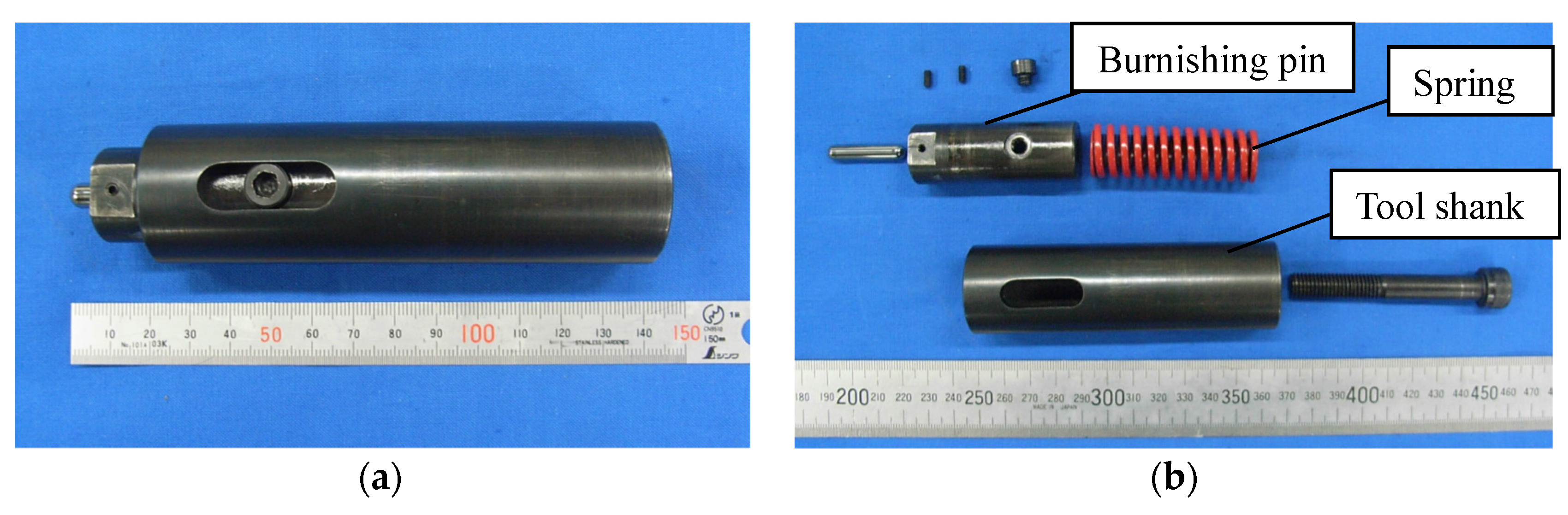
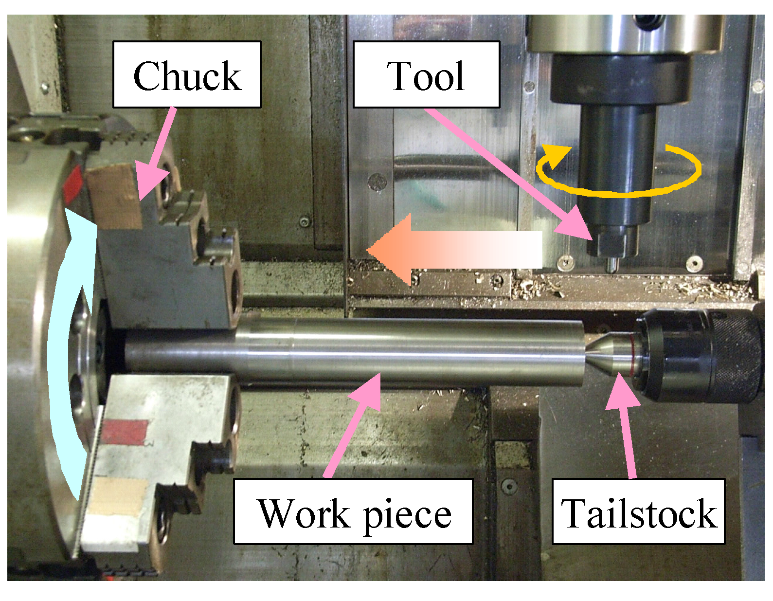
Figure 2 shows the FSB tool assembly. This tool consists of a burnishing pin made of cemented carbide. The burnishing pin was attached at the end of the tool top. A spring was inserted into the tool shank so that the spring preload could be controlled. It was then possible to apply a constant axial force [19]. The experimental setup is shown in Figure 3. The FSB tool was mounted to the tool spindle of a multi-tasking machine (INTEGREX 200-IIIST, Mazak, Oguchi, Japan), and the cylindrical workpiece was set to the work spindle. The workpiece material was 0.45% C steel. The high-speed rotating tool moved in the axial direction of the workpiece rotating at a low speed. The tool path was helical.
After the FSB process was completed, we measured the surface roughness and residual stress on the processed surface. The measurement point was around fourth turn of the helical path. Measurement directions were circumferential and axial on the cylindrical workpiece. The X-ray diffraction method was used for residual stress measurement. Five levels of X-ray incident angles: 0°, 5°, 10°, 15°, and 20°, were used for measurement. A part of the machined surface layer was excised and mounted on resin. It was then ground using SiC paper, and polished with a diamond compound. After polishing, samples were etched using nital solution (5% nitric acid in ethanol). Subsurface microstructural analyses were conducted using an optical microscope. Vickers microhardness measurements were conducted with a load of 0.245 N for 20 s. Hardness on the hardened layer was measured at six points on fourth turn of the helical path and averaged.
The FSB process was applied using different tip radius burnishing tools, and surface roughness, hardness, and residual stress were compared. Figure 4 shows the FSB tool tips, and Table 1 lists the specifications of the burnishing tool. The burnishing tool was a 6-mm diameter cylindrical bar, and the tip was machined to sphere shape. In this study, four levels of tool tip radius were used for the FSB process: R = 3 mm, 10 mm, 20 mm, and 30 mm. Table 2 presents the processing conditions. The FSB process was applied under the condition of tool thrust force P = 750 N, tool spindle speed S = 10,000 min−1, helical pitch p = 2.5 mm, and tool feed rate F = 200 mm/min. The processing conditions were determined based on our previous study [22] using the tool with R = 3 mm. In our previous study, it was shown that tool thrust force P and tool rotation speed S affected strain and heat generation. Lager thrust force (P = 750 N) and higher tool rotation speed (S = 10,000 min−1) increased the strain and the heat generation. As a result, phase transition was occurred on processed surface then hardened layer of 600 HV could be obtained. On the other hand, under the condition of smaller thrust force (P = 500 N) and lower tool rotation speed (S = 1000 min−1), heat generation was lower. Then, the phase transformation did not occur and the work hardened layer was formed on the surface, but its hardness was 300 HV and was lower than that mentioned above. However, the processed surface was plastically deforms, as a result the compressive residual stress was induced. In addition, higher tool feed rate F decreased the heat generation in per unit tool moving length. Then, the thickness of the hardened layer decreased. When considering the above background, processing conditions in this paper was selected based on the conditions where a hardened layer of 600 HV and 500 μm thickness could be obtained when using the tool with R = 3 mm and the effect of the tool tip radius, which could affect the surface deformation and the heat generation, was mainly studied.
3. Results and Discussion
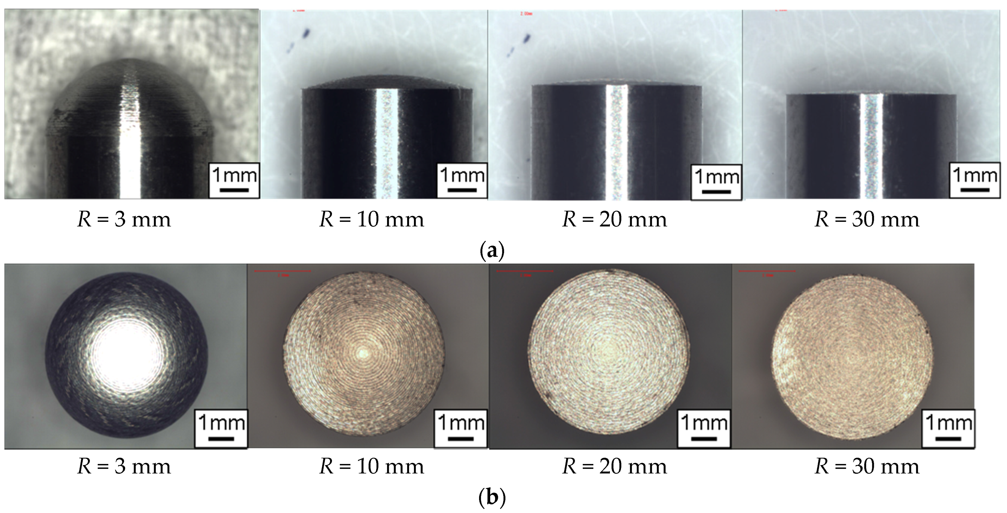
Figure 5a is the photo of R = 3 mm tool taken from the side direction as the typical surface profile of tool after the FSB and Figure 5b shows schematic of tool wear. Wear is evident on the tool tips. It appears that the tool was worn at outer edges of the part where the tool tip is considered to have contacted the work piece, and the center of the worn area is slightly sharp. Figure 6 contains photos of tool tips top view after the FSB process was conducted. The diameter of this area was different depending on tool-tip radius; diameters were larger under the condition of a larger tool tip radius. As shown in Figure 7, the depth of the indentation differed depending on the tool tip radius, and this was thought to be the reason for the difference in the diameter of the contact area between the tool and workpiece. Table 3 lists measurements of contact area diameter and the calculated results for indentation depths. The depth of indentation increased with a smaller tool tip radius. Therefore, it is considered that friction stir affects a deeper layer under the condition of smaller tool tip radius.
Figure 8 shows the volume that stirred by the FSB tool. As shown in Figure 8a, the FSB tool indentation part moves with tool feed, and the shape of the volume that the tool passes during one rotation can be expressed, as shown in Figure 8b. This part is stirred by the burnishing tool. The volume of the stirred part is the same as the semi-cylindrical part shown in Figure 8c. The volume of the stirred part can thus be calculated from the tool tip radius, depth of indentation, and tool moving distance during one rotation. Figure 9 shows the results of the calculated stirred volume during one tool rotation. The stirred volume was larger when a smaller tip radius tool was used.
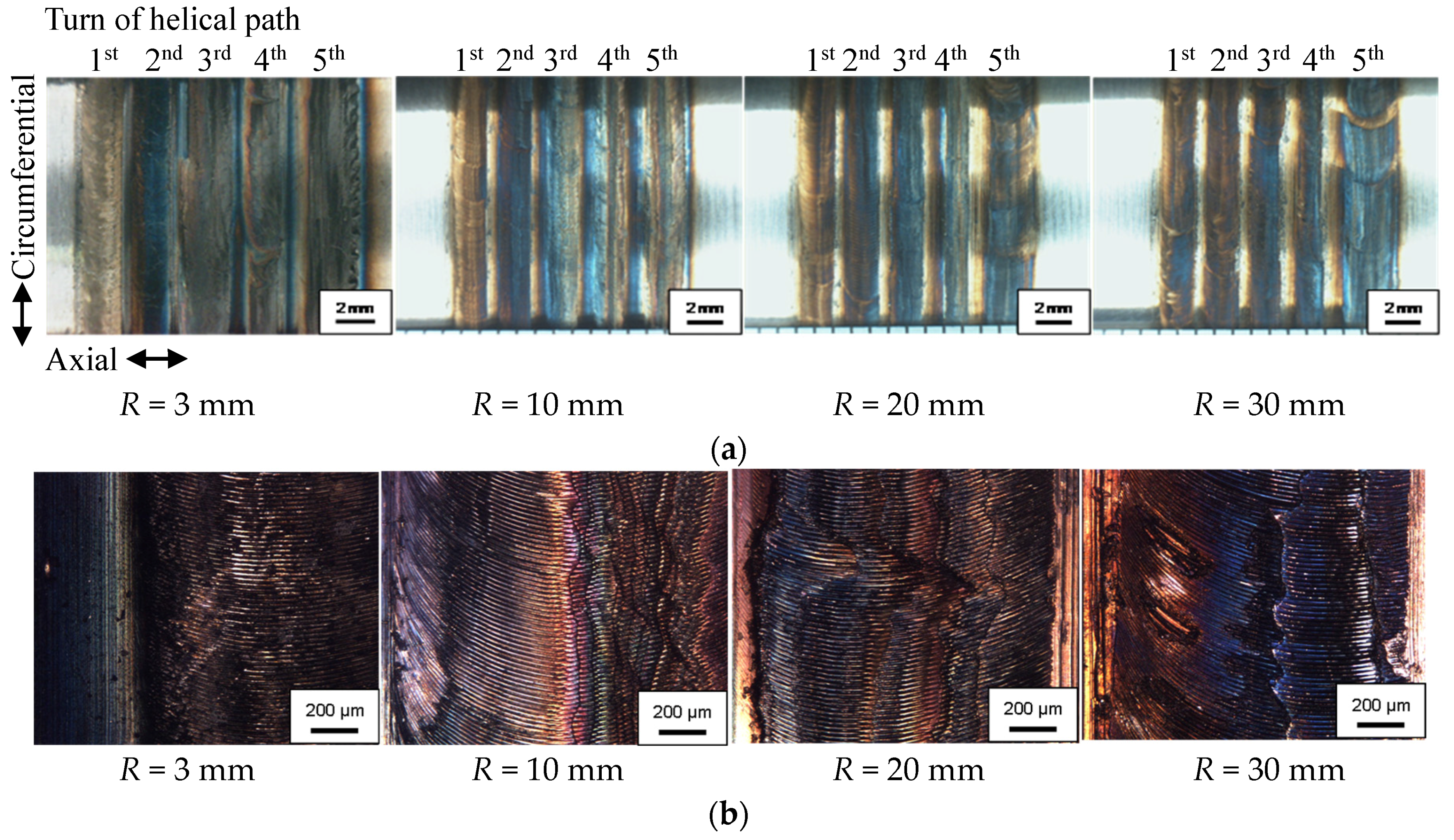
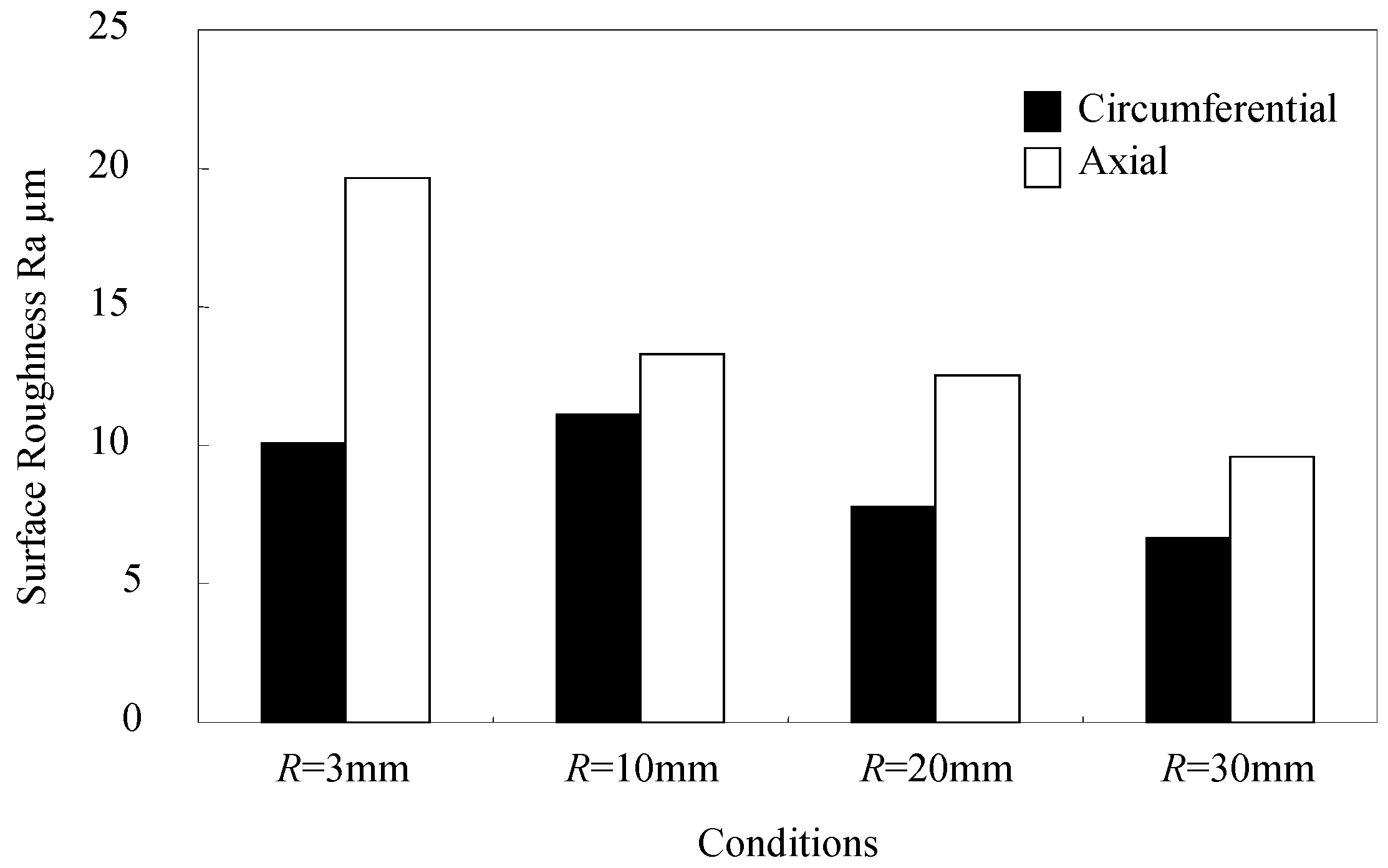
Figure 10 contains photos of the processed surface. It can be seen that the color of the surface changed to bluish brown under all conditions. This indicates that an oxide film covered the surface. Regular striations like circular arcs are also visible on the surface. The processed surface is not flat, and a large height difference can be seen between each turn of the helical path, especially when a smaller tip radius tool was used. Figure 11 shows the surface roughness that was measured in the circumferential and axial directions of the workpiece. Surface roughness along the circumferential direction ranged from Ra = 7–10 µm. Surface roughness along the axial direction was larger than in the circumferential direction, and increased with a decreased tool tip radius. The largest surface roughness was Ra = 20 µm when tool tip radius R was 3 mm; the smallest was Ra = 10 µm when the tool tip radius R was 30 mm.
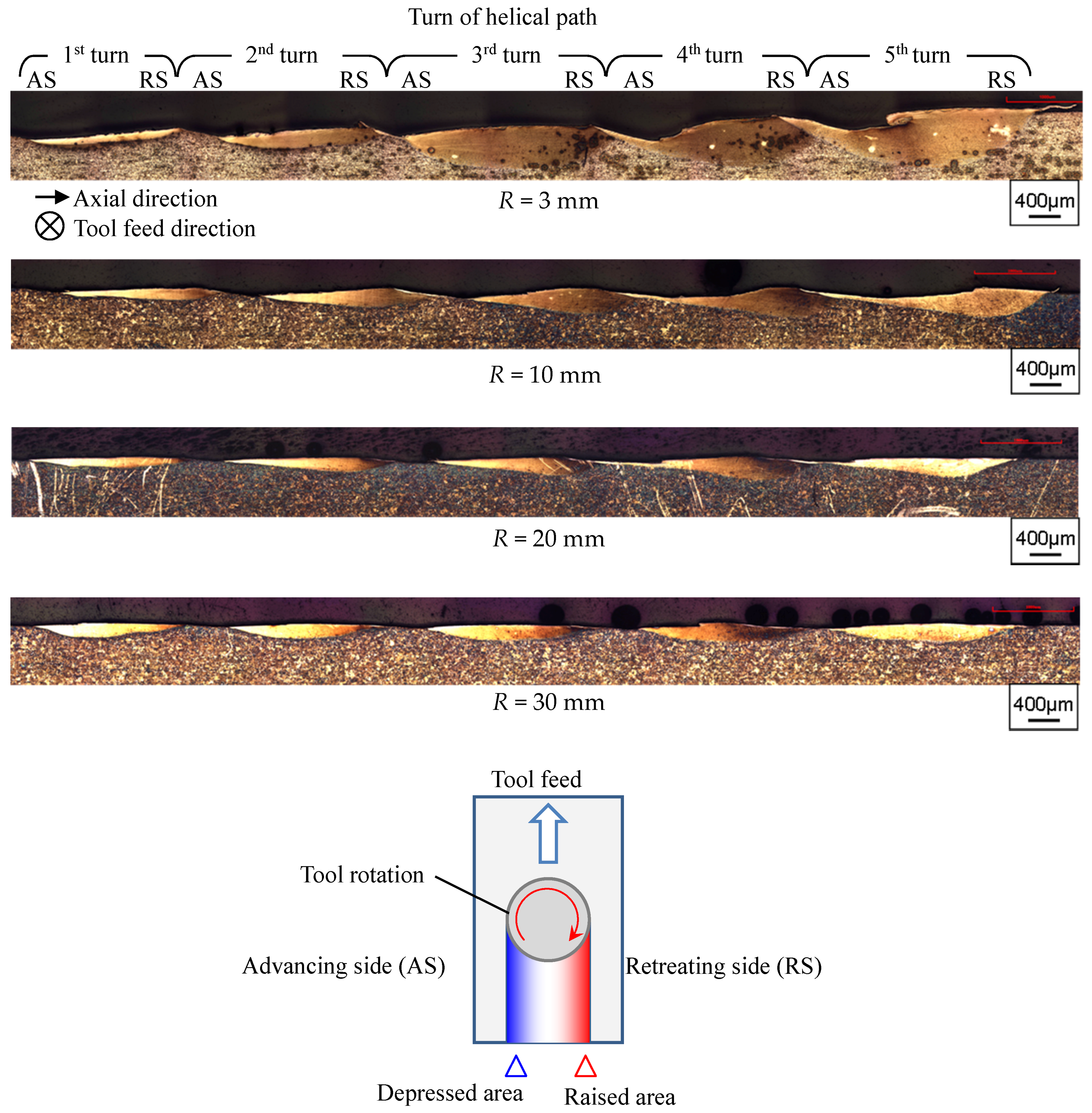
Figure 12 shows etched photomicrographs of a cross section of the processed layer vertical to the tool feed direction. It also shows the surface profile vertical to the tool feed direction. It can be seen that the processed surface profile is not flat; raised and depressed areas were generated on the processed surface when a smaller tip radius tool was used. In the FSB process, the side where the tool peripheral moving direction is the same as the tool feed direction is defined as the advancing side (AS), and the side where the tool peripheral moving direction and the tool advance direction are opposite is defined as the retreating side (RS). The raised area was on the retreating side, and the depressed area on the advancing side.
In the FSB process, it is considered that the material contacting the tool surface is forced to move with the frictional stir action. The relative speed between tool surface and workpiece is higher at the advancing side than the retreating side, because the tool peripheral speed relative to the test piece on the advancing side is the sum of the tool rotation speed and feed speed. It is therefore considered that the material moving from the advancing side piles up on the retreating side, while a smaller amount of material moves from the retreating side to the advancing side. As a result, a raised area is generated on the retreating side and a depressed area on the advancing side.
Stirred volume becomes large when a smaller tip radius tool is used. The large stirred volume made the height difference on the tool path larger. Then, surface roughness increased with a smaller tip radius tool. In addition, it can be seen in Figure 12 that the processed layer was not etched by the nital. The appearance of the enhanced layer was significantly different from that of the base material, which consisted of ferrite and pearlite.
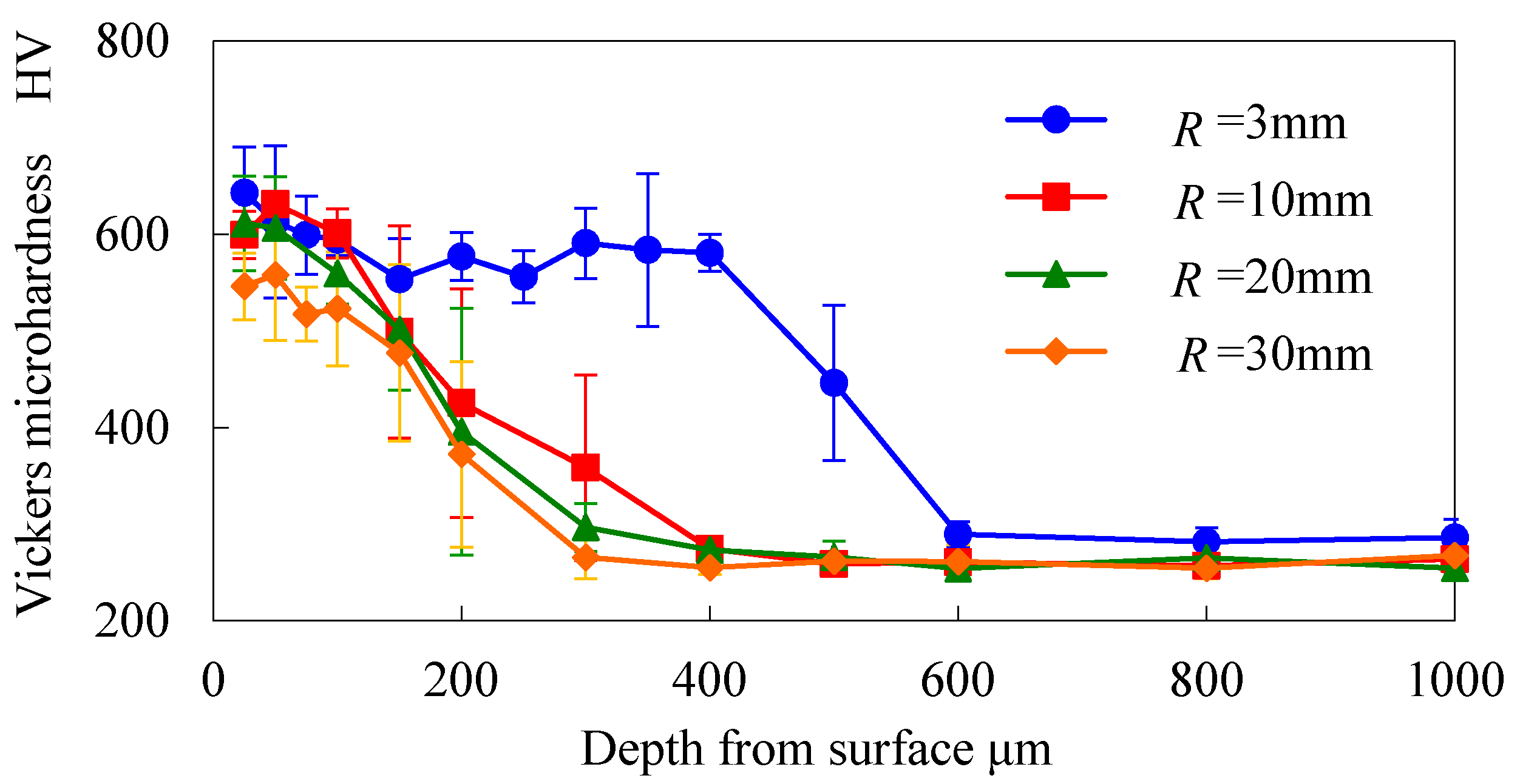
Figure 13 shows the hardness distribution of the cross section. The hardness value of this layer reached 600 HV. The energy input by the FSB process is consumed as large plastic strain and frictional work, then heat is generated. During the FSB process, the surface temperature increased via the extremely high strain and frictional work, and then decreased rapidly. In these situations, a fine-grain martensite is formed in the processed region [22]. The thickness of the hardened layer varied, depending on the tool tip radius, increasing when a smaller tip radius tool was used. This is because the stirred volume during one tool rotation is increased with the smaller tip radius tool, inducing a larger amount of plastic strain to the processing region, and increasing the amount of the heat generation by plastic strain.
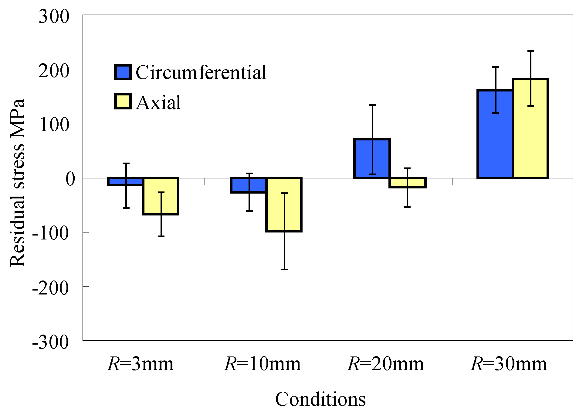
Figure 14 shows the residual stress measured on the processed surface. The residual stress under the condition R = 3 mm and 10 mm was about −100 MPa compressive stress; the residual stress turned tensile as the tip radius tool size increased. A smaller tool tip radius is preferable for inducing compressive residual stress. It is considered that larger plastic strain, which stirs and compresses the surface layer with a smaller tip radius tool, leads to the compressive residual stress. On the other hand, the residual stress becomes tensile as the tool tip radius increases. Under all of the processing conditions, it is considered that the surface temperature was high enough for the austenite transformation. The surface temperature then decreased to room temperature. At this point, thermal contraction occurred due to temperature decrease, and tensile residual stress was induced. When a larger tip radius tool was used, the effect of the thermal contraction was larger than the effect of the plastic strain induced by frictional stirring; as a result, the residual stress became tensile.
4. Conclusions
We studied the FSB process using four levels of tip radius burnishing tools and investigated their effect on surface roughness, hardness and residual stress for 0.45% C steel shaft. The conclusions in this study can be summarized as follows.
- Surface roughness increased under the condition of a smaller tool tip radius. The largest surface roughness was Ra = 20 µm under the condition of a tool tip radius of R = 3 mm, and the smallest surface roughness was Ra = 10 µm under the condition of tool tip radius R = 30 mm.
- The thickness of the hardened layer increased as the tool tip radius decreased. The hardness value of the processed layer reached 600 HV.
- The residual stress on the processed surface was compressive when a smaller tip radius tool was used, and the residual stress turned tensile when a larger tip radius tool was used.
Acknowledgments
This work was supported by JSPS KAKENHI Grant Number JP19360060.
Author Contributions
Yoshimasa Takada and Hiroyuki Sasahara conceived and designed the experiments; Yoshimasa Takada performed the experiments; Yoshimasa Takada and Hiroyuki Sasahara analyzed the data; Yoshimasa Takada wrote the paper.
Conflicts of Interest
The authors declare no conflict of interest.
References
- Kristoffersen, H.; Vomacka, P. Influence of process parameters for induction hardening on residual stresses. Mater. Des. 2001, 22, 637–644. [Google Scholar] [CrossRef]
- Coupard, D.; Palin-luc, T.; Bristiel, P.; Ji, V.; Dumas, C. Residual stress in surface induction hardening of steel: Comparison between experiment and simulation. Mater. Sci. Eng. A 2008, 487, 328–339. [Google Scholar] [CrossRef]
- Torres, M.A.S.; Voorwald, H.J.C. An evaluation of shot peening, residual stress and stress relaxation on the fatigue life of AISI 4340 steel. Int. J. Fatigue 2002, 24, 877–886. [Google Scholar] [CrossRef]
- Bagherifard, S.; Slawik, S.; Fernández-Pariente, I.; Pauly, C.; Mücklich, F.; Guagliano, M. Nanoscale surface modification of AISI 316L stainless steel by severe shot peening. Mater. Des. 2016, 102, 68–77. [Google Scholar] [CrossRef]
- Tosha, K. History and Future of Shot Peening. Mater. Jpn. 2008, 47, 134–139. [Google Scholar] [CrossRef]
- Ding, H.; Shin, Y.C. Laser-assisted machining of hardened steel parts with surface integrity analysis. Int. J. Mach. Tool. Manuf. 2010, 50, 106–114. [Google Scholar] [CrossRef]
- Klocke, F.; Schulz, M.; Gräfe, S. Optimization of the laser hardening process by adapting the intensity distribution to generate a top-hat temperature distribution using freeform optics. Coatings 2017, 7, 77. [Google Scholar] [CrossRef]
- Zhang, G.; Li, D.; Zhang, N.; Zhang, N.; Duan, S. Thermal-sprayed coatings on bushing and sleeve-pipe surfaces in continuous galvanizing sinking roller production line applications. Coatings 2017, 7, 113. [Google Scholar] [CrossRef]
- O’Sullivan, C.; O’Hare, P.; Byrne, G.; O’Neill, L.; Ryan, K.B.; Crean, A.M. A modified surface on titanium deposited by a blasting process. Coatings 2011, 1, 53–71. [Google Scholar] [CrossRef]
- Sasahara, H. The effect on fatigue life of residual stress and surface hardness resulting from different cutting conditions of 0.45%C steel. Int. J. Mach. Tool. Manuf. 2005, 45, 131–136. [Google Scholar] [CrossRef]
- Mahajan, D.; Tajane, R. A review on ball burnishing process. Int. J. Sci. Res. Publ. 2013, 3, 1–8. [Google Scholar]
- Salmi, M.; Huuki, J.; Ituarte, I.F. The ultrasonic burnishing of cobalt-chrome and stainless steel surface made by additive manufacturing. Prog. Addit. Manuf. 2017, 31–41. [Google Scholar] [CrossRef]
- Mishra, R.S.; Ma, Z.Y. Friction stir welding and processing. Mater. Sci. Eng. R Rep. 2005, 50, 1–78. [Google Scholar] [CrossRef]
- Grewal, H.S.; Arora, H.S.; Agrawal, A. Surface modification of hydroturbine steel using friction stir processing. Appl. Surf. Sci. 2013, 268, 547–555. [Google Scholar] [CrossRef]
- Nia, A.A.; Omidvar, H.; Nourbakhsh, S.H. Effects of an overlapping multi-pass friction stir process and rapid cooling on the mechanical properties and microstructure of AZ31 magnesium alloy. Mater. Des. 2014, 58, 298–304. [Google Scholar] [CrossRef]
- Lorenzo-Martin, C.; Ajayi, O.O. Rapid surface hardening and enhanced tribological performance of 4140 steel by friction stir processing. Wear 2015, 332–333, 962–970. [Google Scholar] [CrossRef]
- Saito, N.; Shigematsu, I. Friction stir processing—A new technique for microstructure control of metallic materials. J. Jpn. Inst. Light Met. 2007, 57, 492–498. [Google Scholar] [CrossRef]
- Fujii, H.; Yamaguchi, Y.; Kikuchi, T.; Kiguchi, S.; Nogi, K. Surface hardening of two cast irons by friction stir processing. J. Phys. Conf. Ser. 2009, 165, 012013. [Google Scholar] [CrossRef]
- Sasahara, H.; Kiuchi, S.; Yata, T.; Murase, H.; Tominaga, K. Generation of surface hardened layer on 0.45%C steel by frictional stir burnishing. In Proceedings of the 9th Global Congress on Manufacturing and Management, Gold Coast, Australia, 12–14 November 2008. [Google Scholar]
- Kiuchi, S.; Sasahara, H. Temperature history and metallographic structure of 0.45%C steel processed by friction stir burnishing. In Proceedings of the 5th Leading Edge Manufacturing 21st Century, Omiya, Japan, 2–4 December 2009; pp. 359–364. [Google Scholar]
- Kiuchi, S.; Sasahara, H. Temperature History and Metallographic Structure of 0.45%C Steel Processed by Frictional Stir Burnishing. J. Adv. Mech. Des. Syst. 2010, 4, 838–848. [Google Scholar] [CrossRef]
- Takada, Y.; Sasahara, H. Frictional stir burnishing on double helical path to satisfy both high hardness and compressive residual stress. Trans. Jpn. Soc. Mech. Eng. 2015, 81, 15-00350. [Google Scholar] [CrossRef]
- Tanaka, R.; Okada, R.; Nakagawa, T.; Furumoto, T.; Hosokawa, A.; Ueda, T. Creation of modified surface layer with superior roughness by combination machining. Trans. Jpn. Soc. Mech. Eng. Ser. C 2012, 3605–3614. [Google Scholar] [CrossRef]
Figure 1.
Scheme of the friction stir burnishing.
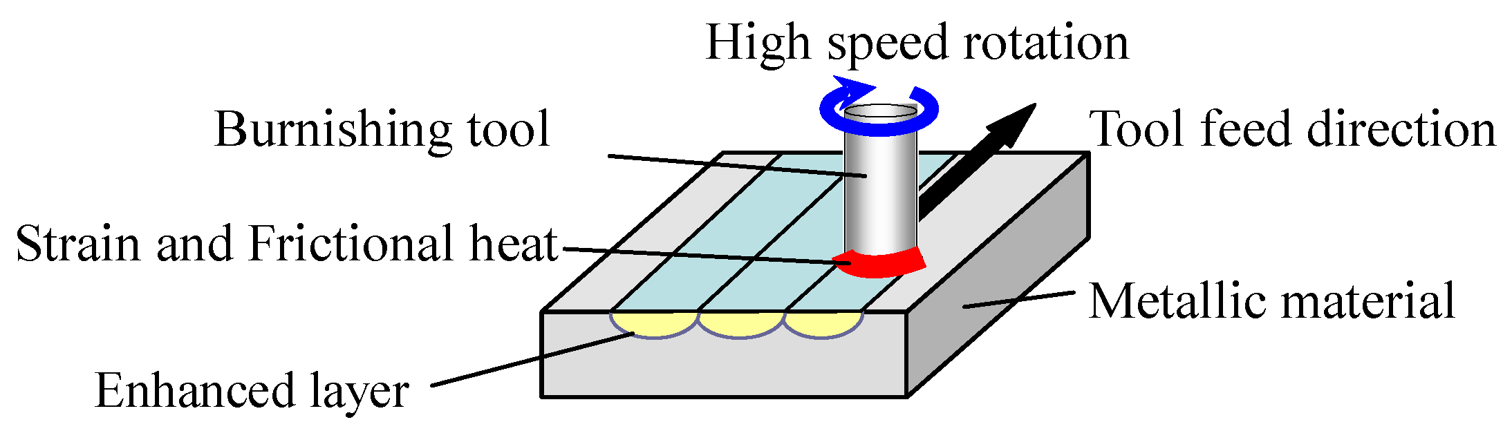
Figure 2.
Tool for friction stir burnishing (FSB): (a) External view; and (b) Components.

Figure 3.
The experimental test stand.

Figure 4.
Tip shape of tool: (a) Side view; (b) Over top view.

Figure 5.
Tool tip shape after processing: (a) Side view of R = 3 mm tool; and (b) Schematic of tool wear.
Figure 5.
Tool tip shape after processing: (a) Side view of R = 3 mm tool; and (b) Schematic of tool wear.
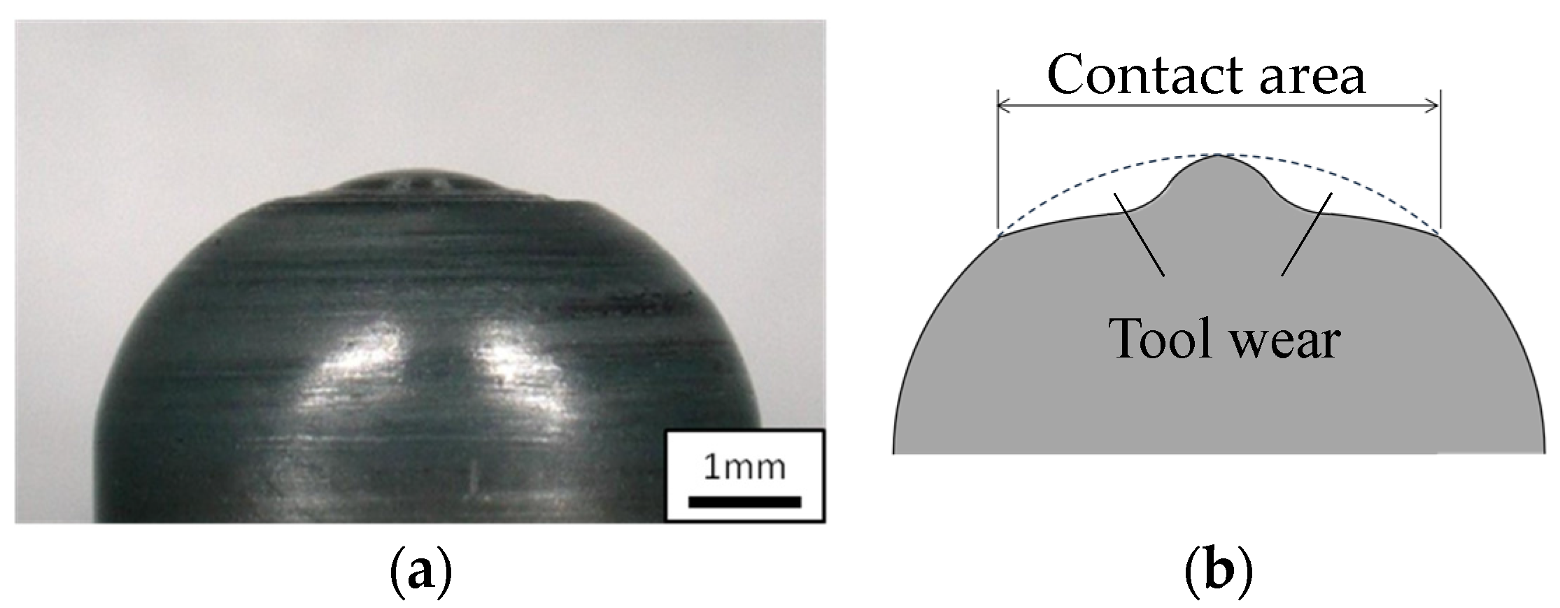
Figure 6.
Over top view of tool tip after FSB processing.

Figure 7.
Schematics of contact area.
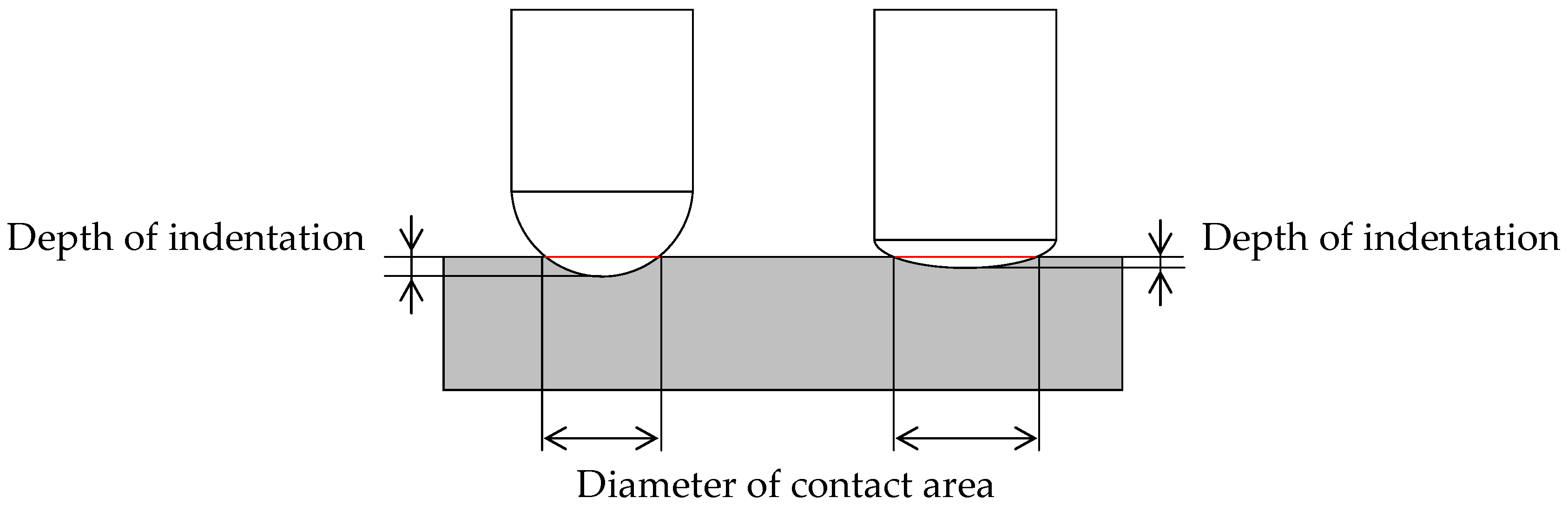
Figure 8.
Schematic of stirred volume by the FSB tool: (a) Tool indentation part and tool movement; (b) The volume that is stirred by the tool passing during one rotation; and (c) Calculation of stirred volume during one tool rotation.
Figure 8.
Schematic of stirred volume by the FSB tool: (a) Tool indentation part and tool movement; (b) The volume that is stirred by the tool passing during one rotation; and (c) Calculation of stirred volume during one tool rotation.
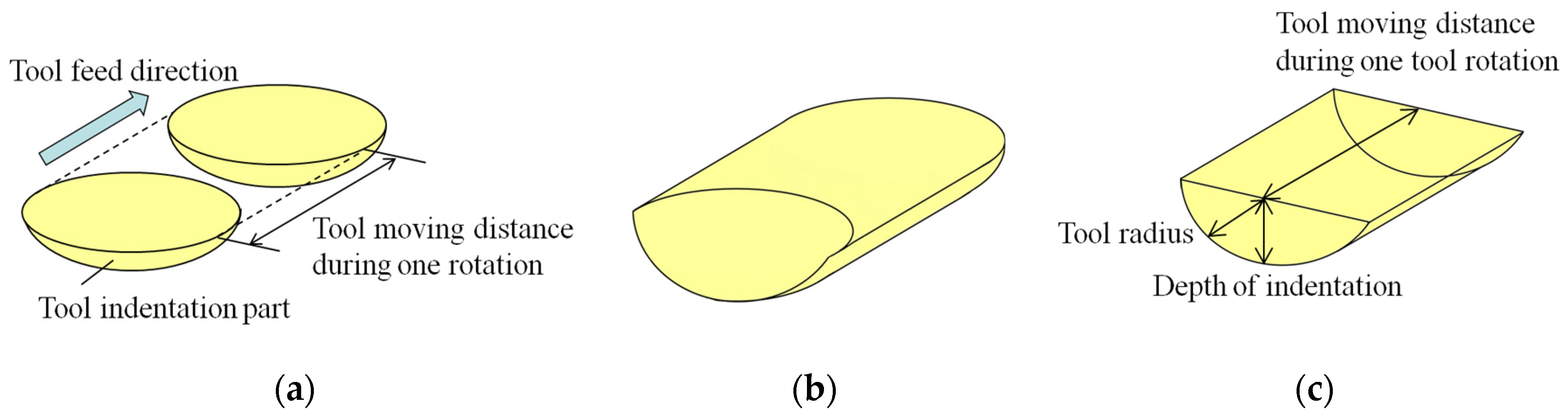
Figure 9.
Stirred volume per revolution.
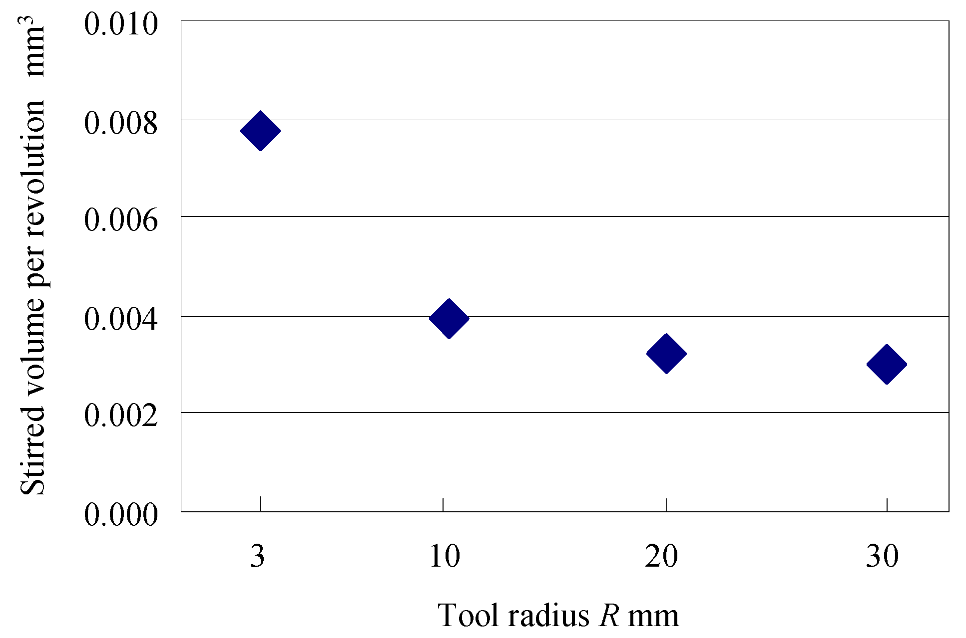
Figure 10.
Processed surfaces: (a) Overall view; and (b) Enlarged view.

Figure 11.
Surface roughness.

Figure 12.
Cross sections of processed surfaces.

Figure 13.
Hardness distributions on cross section of processed surfaces.

Figure 14.
Residual stresses on processed surface.


Table 1.
Specification of burnishing tool.
| Tool Tip Shape | Tool Radius R (mm) | Tool Material | Tool Dimension (mm) | |||
|---|---|---|---|---|---|---|
| Sphere | 3 | 10 | 20 | 30 | Cemented carbide | φ6 × 30 |
Table 2.
Processing condition.
| Tool Thrust Force P (N) | Tool Spindle Speed S (min−1) | Helical Pitch p (mm) | Feed Rate F (mm/min) | Tool Material | Workpiece Material |
|---|---|---|---|---|---|
| 750 | 10,000 | 2.5 | 200 | Cemented carbide | 0.45% C steel |
Table 3.
Diameter of contact area and depth of indentation.
| Tool Radius R (mm) | Diameter of Contact Area (mm) | Depth of Indentation (mm) |
|---|---|---|
| 3 | 2.4 | 0.24 |
| 10 | 2.9 | 0.10 |
| 20 | 3.4 | 0.07 |
| 30 | 3.8 | 0.06 |
© 2018 by the authors. Licensee MDPI, Basel, Switzerland. This article is an open access article distributed under the terms and conditions of the Creative Commons Attribution (CC BY) license (http://creativecommons.org/licenses/by/4.0/).
Share and Cite
MDPI and ACS Style
Takada, Y.; Sasahara, H. Effect of Tip Shape of Frictional Stir Burnishing Tool on Processed Layer’s Hardness, Residual Stress and Surface Roughness. Coatings 2018, 8, 32. https://doi.org/10.3390/coatings8010032
AMA Style
Takada Y, Sasahara H. Effect of Tip Shape of Frictional Stir Burnishing Tool on Processed Layer’s Hardness, Residual Stress and Surface Roughness. Coatings. 2018; 8(1):32. https://doi.org/10.3390/coatings8010032
Chicago/Turabian StyleTakada, Yoshimasa, and Hiroyuki Sasahara. 2018. "Effect of Tip Shape of Frictional Stir Burnishing Tool on Processed Layer’s Hardness, Residual Stress and Surface Roughness" Coatings 8, no. 1: 32. https://doi.org/10.3390/coatings8010032
Note that from the first issue of 2016, this journal uses article numbers instead of page numbers. See further details here.