Article

Influence of Nitrogen Partial Pressure on Microstructure and Tribological Properties of Mo-Cu-V-N Composite Coatings with High Cu Content

1
School of Electromechanical Engineering, Guangdong University of Technology, Guangzhou 510006, China
2
School of Mechanical Engineering, Guilin University of Aerospace Technology, Guilin 541004, China
*
Authors to whom correspondence should be addressed.
Coatings 2018, 8(1), 24; https://doi.org/10.3390/coatings8010024
Submission received: 19 November 2017 / Revised: 25 December 2017 / Accepted: 27 December 2017 / Published: 4 January 2018
(This article belongs to the Special Issue Hybrid Surface Coatings & Process (Selected Papers from HyMaP 2017))

Abstract

:
In this study, Mo-Cu-V-N composite coatings with high Cu content of ~18 at.% were deposited on 316L stainless steel and YT14 cemented carbide substrates by high power impulse magnetron sputtering in Ar–N2 gas mixtures. The influence of N2 partial pressure was investigated with respect to the microstructure and tribological properties of the coatings. The results indicated that the Mo-Cu-V-N composite coatings exhibited FCC B1-MoN phase with a strong (200) preferred orientation, and Cu phase was found to exist as metallic species. As the N2 partial pressure increased from 0.11 to 0.35 Pa, the peak intensity of (200) plane decreased gradually and simultaneous peak broadening was observed, which was typical for grain refinement. With increasing the N2 partial pressure, the columnar microstructure became much coarser, which led to the decrease of residual stress and hardness. The Mo-Cu-V-N composite coatings with high Cu content exhibited a relatively low wear rate of 10−8 mm3/N·m at 25 °C, which was believed to be attributed to the mixed lubricious oxides of MoO2, CuO and V2O5 formed during tribo-oxidation, which cannot be formed in the coatings with low Cu content. When the wear temperature was increased up to 400 °C, the wear rate increased sharply up to 10−6 mm3/N·m despite the formation of lubricious oxides of MoO3/CuMoO4 and V2O5. This could be due to the loss of nitrogen and pronounced oxidation at high temperatures, which led the wear mechanism to be transformed from mild oxidation wear to severe oxidation wear.

1. Introduction

In the last decade, solid lubricants have been developed to achieve favorable abrasion resistance and good lubricating capability in various tribological applications [1,2,3]. However, the tribological effectiveness of solid lubricants often begins to fail due to the thermal degradation or oxidation at elevated temperatures [4,5,6]. In recent years, some lubricious materials at elevated temperatures have been investigated by using oxide materials. These lubricious oxides are often referred to as Magnéli phases, which usually shows easy crystallographic shear planes, good oxidation stability and excellent tribological properties [7]. Among these, molybdenum and vanadium nitrides have been achieved to reduce the friction coefficient at high temperatures. The self-lubricating effect is based on the formation of lubricious oxides of MoO3 [8,9,10] and V2O5 [11,12,13]. In addition, some soft metals also possess lubrication properties due to their low shear strength and high plasticity. Recently, soft metals like Cu have been added into Mo-N coatings to form nanocomposite coatings to achieve better tribological performance [14,15]. Thus, multi-functional self-lubricating coatings can be obtained by the addition of these alloying elements.
Up to now, few studies have reported on the self-lubricating coatings deposited by high power impulse magnetron sputtering (HIPIMS). The high plasma density and large fraction of ionized species created in a high-power impulse magnetron sputtering discharge allows for a better control of the process parameters [16]. It has been well documented that the microstructure and mechanical properties of magnetron sputtered metal nitride coatings strongly depend on the nitrogen flow rate [17,18,19]. While the effect of nitrogen partial pressure on the microstructure and mechanical properties of Mo-Cu-V-N composite coatings has been investigated in our previous work [20], the formation of CuMoO4 lubricious oxides has not been found during the tribological test at room temperature, which would be due to the low content of Cu in the Mo-Cu-V-N composite coatings. It has been reported that the average friction coefficient of the Mo-Cu-N coatings decreased from 0.40 to 0.21 with increasing Cu content up to 11 at.% due to the formation of lubricious oxides of CuMoO4, which possesses better self-lubricating behavior than MoO3 due to difference in ionic potential of MoO3 and CuO [21]. It also has been reported that double oxides from binary alloy systems can effectively reduce the coefficient of friction [22]. It is essential to reduce the friction coefficient and improve the wear resistance of the self-lubricating coatings for industrial applications. In addition, studies on the tribological properties of Mo-Cu-V-N coatings at elevated temperatures are rarely reported in the literature.
Therefore, the aim of this work is to prepare the Mo-Cu-V-N composite coatings with high Cu content to further investigate the influence of N2 partial pressure on the microstructure, residual stress and tribological properties, and to find out the wear mechanism of the self-lubricating coatings at elevated temperatures up to 400 °C.

2. Experimental

2.1. Coating Deposition

Mo-Cu-V-N composite coatings were deposited on the polished AISI 316L stainless steel and YT14 (WC-14%TiC-8%Co) cemented carbide substrates by high power impulse magnetron sputtering unit (ProChina Limited, Beijing, China) using a rectangular spliced target (69 mm × 443 mm). The Mo-Cu-V spliced target with three kinds of metal targets of Mo (99.99%), Cu (99.99%) and V (99.99%) was installed on the side walls of the chamber. Similar schematic diagrams of the Mo-Cu-V spliced target had been used in our previous studies [20]. The only difference in this work was the location of the rotational substrate holder, which was located in the middle center of the spliced target to deposit the coatings with high Cu content. The stainless steel was selected as a substrate for testing of residual stress, while the cemented carbide substrates were used for the test of microstructure and mechanical properties of the Mo-Cu-V-N coatings. All the substrates were ultrasonically cleaned first in acetone and then in alcohol for 10 min, respectively. The substrates were then blown dry with compressed air and mounted on the substrate holder, which was rotated at a speed of 3 rpm. Prior to the coating deposition, the chamber was evacuated to a base pressure of 5.0 × 10⁻³ Pa, and the substrate temperature was then heated to 100 °C. To remove surface contaminates, the substrates were etched by Ar plasma with a DC bias of −1000 V at a gas pressure of 1.8 Pa for 15 min. During the deposition, the Mo-Cu-V-N composite coatings were deposited by HIPIMS at a working pressure of 0.7 Pa with the N2 partial pressure increased from 0.11 to 0.35 Pa. The coating deposition time was maintained at 180 min to obtain the coatings with thickness ranging from 2.1 to 2.4 μm. The detail deposition conditions is summarized in Table 1.

2.2. Coating Characterization

The morphologies and chemical composition of the coatings were examined using a scanning electron microscope (SEM, FEI Nano430, Amsterdam, The Netherlands) equipped with an energy-dispersive X-ray spectrometer (EDS). The phase structure of the as-deposited coatings was characterized on an X-ray diffraction (XRD, Bruker D8 Advance, Bruker AXS, Karlsruhe, Germany) machine in the θ/2θ geometry using Cu Kα radiation (40 kV and 40 mA). The chemical structure was investigated using X-ray photoelectron spectrometer (XPS, ESCALAB 250xi, Thermo Fisher Scientific, Waltham, MA, USA), and an Al Kα X-ray source (13 kV and 15 mA) was used. The scanning step for the full spectrum and individual spectrum was set at 1 and 0.1 eV, respectively. The XPS spectra were obtained after removing the surface contamination layer of the sample by in situ sputtering with Ar+ ions (3 kV) for 120 s, and were calibrated by carbon peak C1s at 284.6 eV.
The residual stress was measured by a Film Stress Tester (FST-1000, Supro Instruments, Shenzhen, China) according to the substrate curvature method based on Stoney’s equation [23]. The coating hardness (H) and elastic modulus (E) were measured by nanoindenter (NHT2, CSM, Peseux, Switzerland) with a Berkovich diamond indenter. The maximum applied load was 10 mN, and the indentation depth was kept below 10% of the coating thickness. The tribological properties were investigated by using a high-temperature ball-on-disc tribometer (THT, CSM) in air at 25 °C and 400 °C. Al2O3 ball with a 6-mm diameter was used as the counterpart. The sliding tests were conducted with a rotational speed of 400 r/min under a load of 5 N and a fixed period of 5000 rotating cycles. To measure the wear loss, the three-dimensional morphologies and two-dimensional (2D) cross-sectional profile of the wear tracks were obtained using a white light interferometer (Contour GT-X3, Bruker, Tucson, AZ, USA). The wear rates were calculated as the worn volume per normal load and the sliding distance.

3. Results and Discussion

3.1. Microstructure and Mechanical Properties

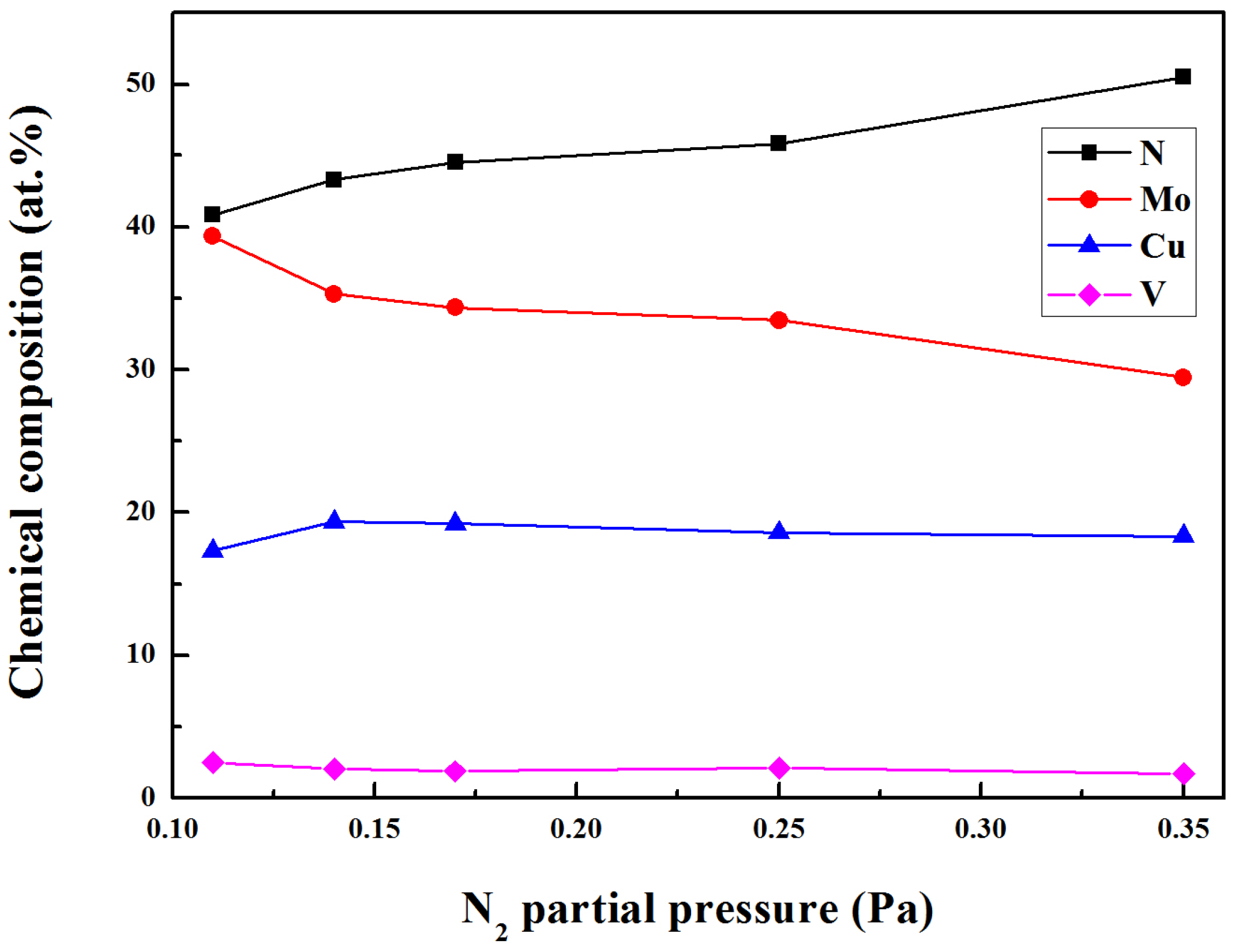
The chemical composition of Mo-Cu-V-N composite coatings deposited at various N2 partial pressures are shown in Figure 1. As the N2 partial pressure increased from 0.11 to 0.35 Pa, the Mo content decreased from 39.4 at.% to 29.5 at.%. At higher N2 partial pressure, the N2+/Ar+ ratio increased and hence the sputtering yield of Mo atoms were reduced. As expected, the N content increased from 40.9 at.% to 50.5 at.%. Meanwhile, small changes were found in both the Cu content and V content, which were in the range of 17.3 at.% to 19.3 at.% and 1.7 at.% to 2.5 at.%, respectively. While the Cu content in the range of 9.2 at.% to 11.4 at.% was achieved in the Mo-Cu-V-N coatings with low Cu content [20]. The high content of Cu and low content of V in the Mo-Cu-V-N composite coatings deposited by HIPIMS could be explained by the different sputtering yields [24].
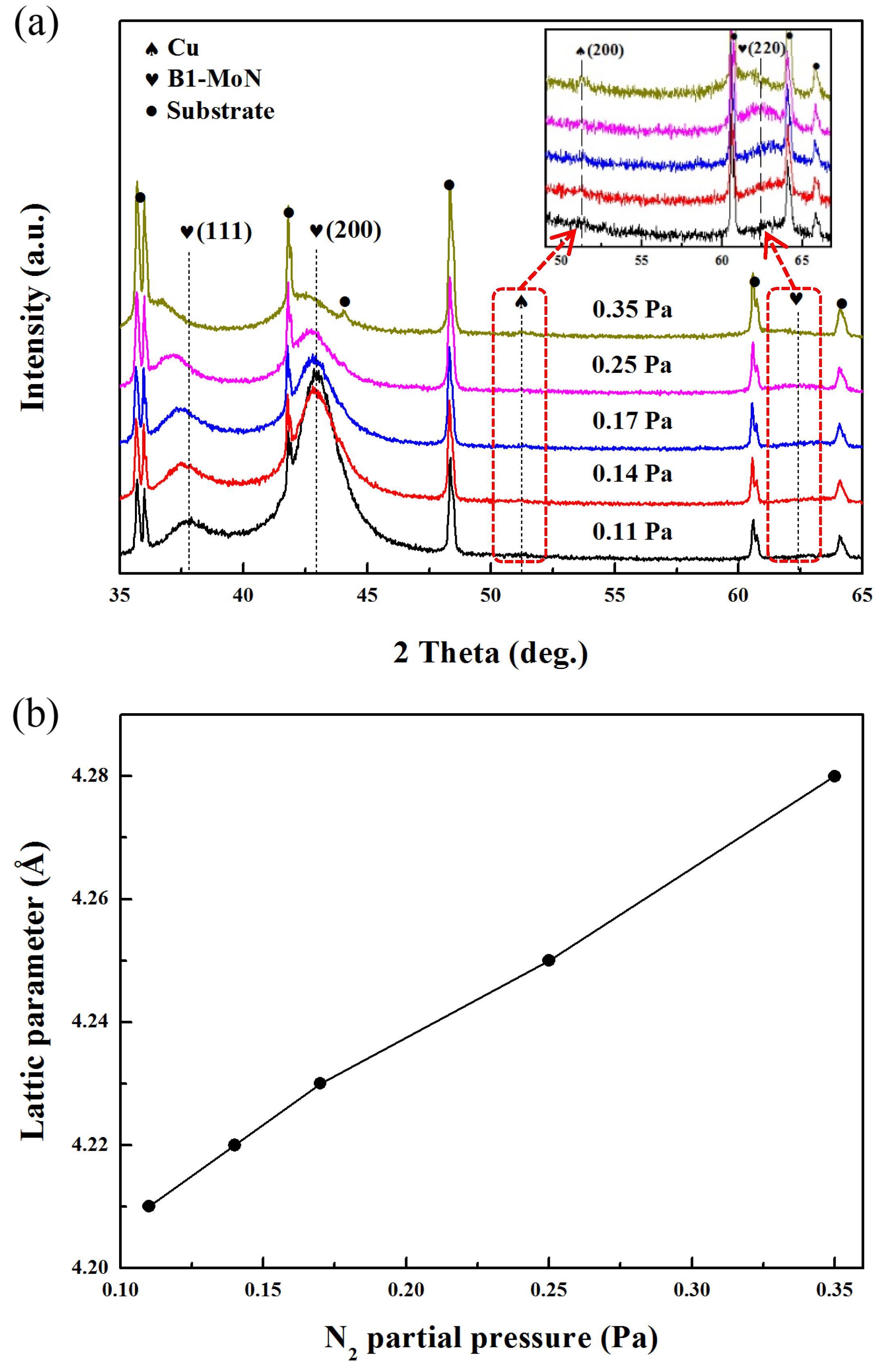
Figure 2a shows the XRD patterns of Mo-Cu-V-N composite coatings deposited at different N2 partial pressures. For all the coatings, three diffraction peaks at about 37.6°, 42.9° and 62.5° were corresponding to (111), (200) and (220) crystal planes of face-centered-cubic Mo-N phase, respectively. Meanwhile, the Mo-Cu-V-N composite coatings revealed (200) diffraction peak of face-centered-cubic structure at about 51.3°, which corresponded to the FCC Cu phase. While no diffraction peaks of vanadium nitride phase were observed in the Mo-Cu-V-N composite coatings, which could be due to the low content of V in the coatings. At the N2 partial pressure of 0.11 Pa, the peak intensity of (200) plane was much higher than that of the other FCC peaks, indicating a high preferred orientation of the (200) grain. While the Mo-Cu-V-N composite coatings with Cu content below ~11 at.% exhibited FCC B1-MoN phase with a (111) preferred orientation [20]. Pelleg et al. [25] had reported that (111) orientation with the lowest strain energy might be expected when the strain energy was significant, and (200) orientation with the lowest surface energy may be observed when the surface energy was ultimately dominant. Thus, with the increase of the Cu content, the preferred orientation of Mo-Cu-V-N coatings changed from (111) to (200) due to the increase of surface energy and the decrease of strain energy. However, with the increase of N2 partial pressure, the peak intensity of (200) plane decreased gradually with simultaneous peak broadening being observed, which was typical for the grain refinement. Similar results had been reported by Kim et al.; the peak intensity decreased with increase in nitrogen flow rate [15]. When the N2 flow rate increased, N provided reaction sites, which in turn increased nucleation sites, and then reduced the grain growth. In addition, the XRD peak positions gradually shifted toward lower diffraction angles with the increase of N2 partial pressure, indicating an increase in lattice parameters of the coatings. To analyze the peak shift quantitatively, lattice parameters of the Mo-N phase were calculated from the (200) peaks, as shown in Figure 2b. As the N2 partial pressure increased from 0.11 to 0.35 Pa, the lattice parameters increased from 4.21 to 4.28 Å, which could be explained by the fact that the excess nitrogen atoms occupied interstitial positions of Mo-Cu-V-N coatings. According to Ref. [26], two FCC phases exist in the Mo-N system: γ-Mo2N with lattice parameters of 4.16–4.19 Å and B1-MoN with lattice parameters of 4.20–4.27 Å. Therefore, the FCC Mo-N phase would correspond to the FCC B1-MoN phase. While for the Mo-Cu-V-N coatings with low Cu content [20], the phase structure was found to change from B1-MoN to hex δ-MoN phase with increasing the N2 partial pressure, which would be due to the higher nitrogen content in the coatings.
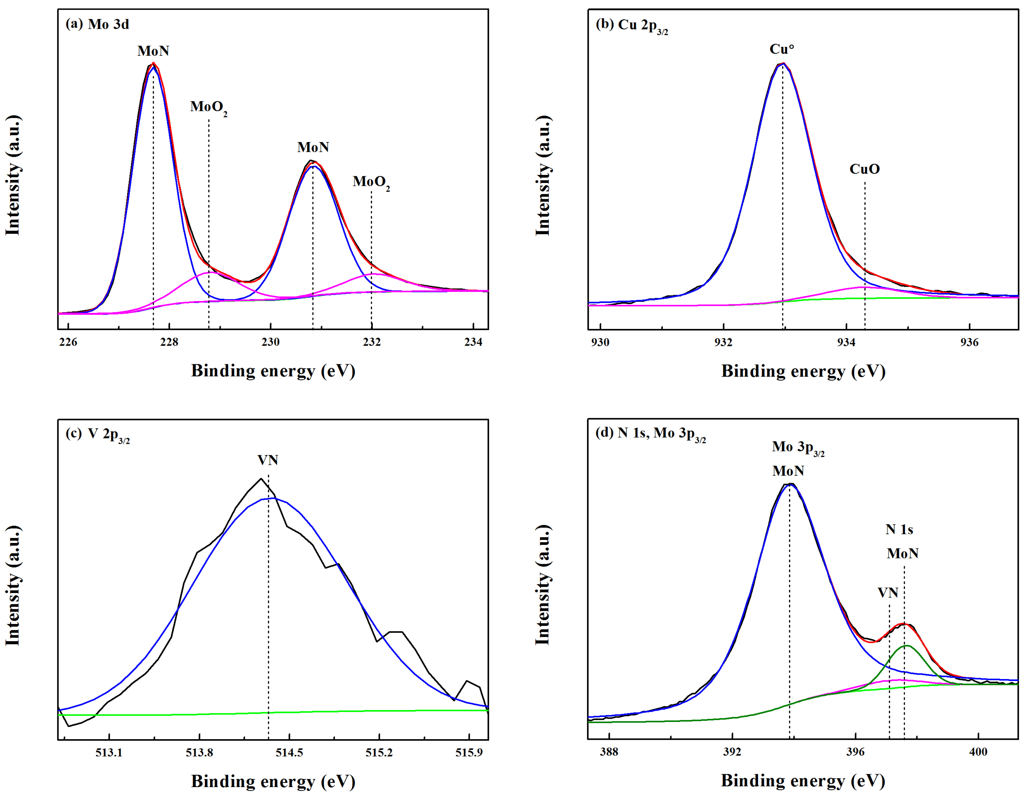
In order to obtain insight into the chemical bonding states, the Mo-Cu-V-N composite coating deposited at the N2 partial pressure of 0.11 Pa was investigated by using XPS. The C 1s peak at 284.6 eV had been used as a reference to calibrate the XPS spectra. As shown in Figure 3a, the fitted Mo 3d spectrum centered at 227.7 eV and 230.8 eV were recognized as MoN (3d5/2) and MoN (3d3/2), respectively. In addition, the peaks with a high binding energy of 228.8 eV and 232.0 eV were also found in the Mo 3d spectrum, which corresponded to MoO2 (3d5/2) and MoO2 (3d3/2), respectively [27]. It indicated that the surface of Mo-Cu-V-N composite coating had been oxidized slightly, and most of the Mo atoms were involved in nitride bonding. Similar to the XPS analysis of as-deposited MoNx coatings, we found that the surface of MoNx coating deposited at low N2 flow rate had already been oxidized before the ball on disc test [28]. In Figure 3b, the fitted Cu 2p3/2 spectrum showed two components at 932.9 eV and 934.3 eV, which were identified as the characteristic signals of the metallic copper Cu0 and CuO, respectively. It indicated that Cu did not participate in the form of nitrides in the coatings, which was in accordance with the XRD results (Figure 2a). In addition, the formation of CuO oxides had not been found in the Mo-Cu-V-N composite coatings, which would be due to the low content of Cu [20]. As seen in Figure 3c, the peak with a binding energy of 514.3 eV was found in the V 2p3/2 spectra, which was identified as the characteristic signal of VN. In Figure 3d, the N 1s spectrum can be deconvoluted into two peaks: a major peak at 397.6 eV and a weak peak at 397.1 eV, corresponding to the MoN and VN, respectively.
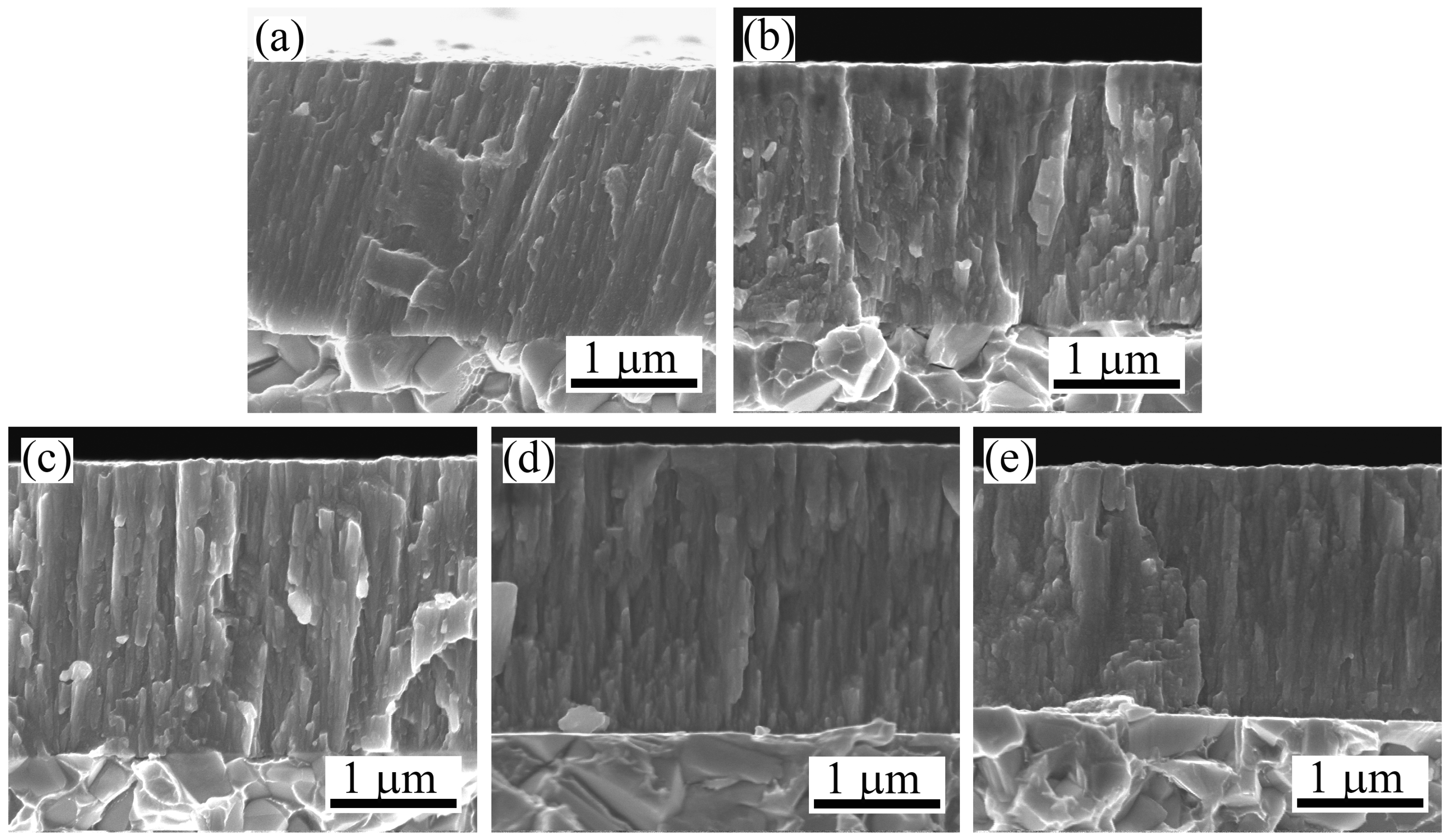
Figure 4 displays the cross-sectional SEM micrographs of Mo-Cu-V-N composite coatings deposited at different N2 partial pressures. It can be clearly seen that all the coatings exhibited columnar-type structure. As shown in Figure 4a, the compact columnar microstructure can be clearly observed for the Mo-Cu-V-N coating deposited at the N2 partial pressure of 0.11 Pa. With the increase of N2 partial pressure, much coarser columnar microstructure appeared and grew outward from the coating–substrate interface to the Mo-Cu-V-N coating surface (Figure 4c–e). This phenomenon can be explained by the higher nitrogen concentration where the sputtering yield of metal atoms is more reduced, which would lead to the effect of high-energy ions bombarding being decreased during the deposition. Based on the coating thickness measured from cross-sectional SEM micrographs, it was found that the coating thickness decreased from 2.4 to 2.1 μm with an increase in the N2 partial pressure from 0.11 to 0.35 Pa. Since the total working pressure was held constant and the N2 partial pressure was increased, the sputtering Ar ions was then decreased, resulting in increased target poisoning and, thus, a decreased deposition rate. In addition, it had been reported that the higher nitrogen partial pressure was increased, more current was carried by nitrogen ion in the plasma, thus the depositing rate is reduced [29].
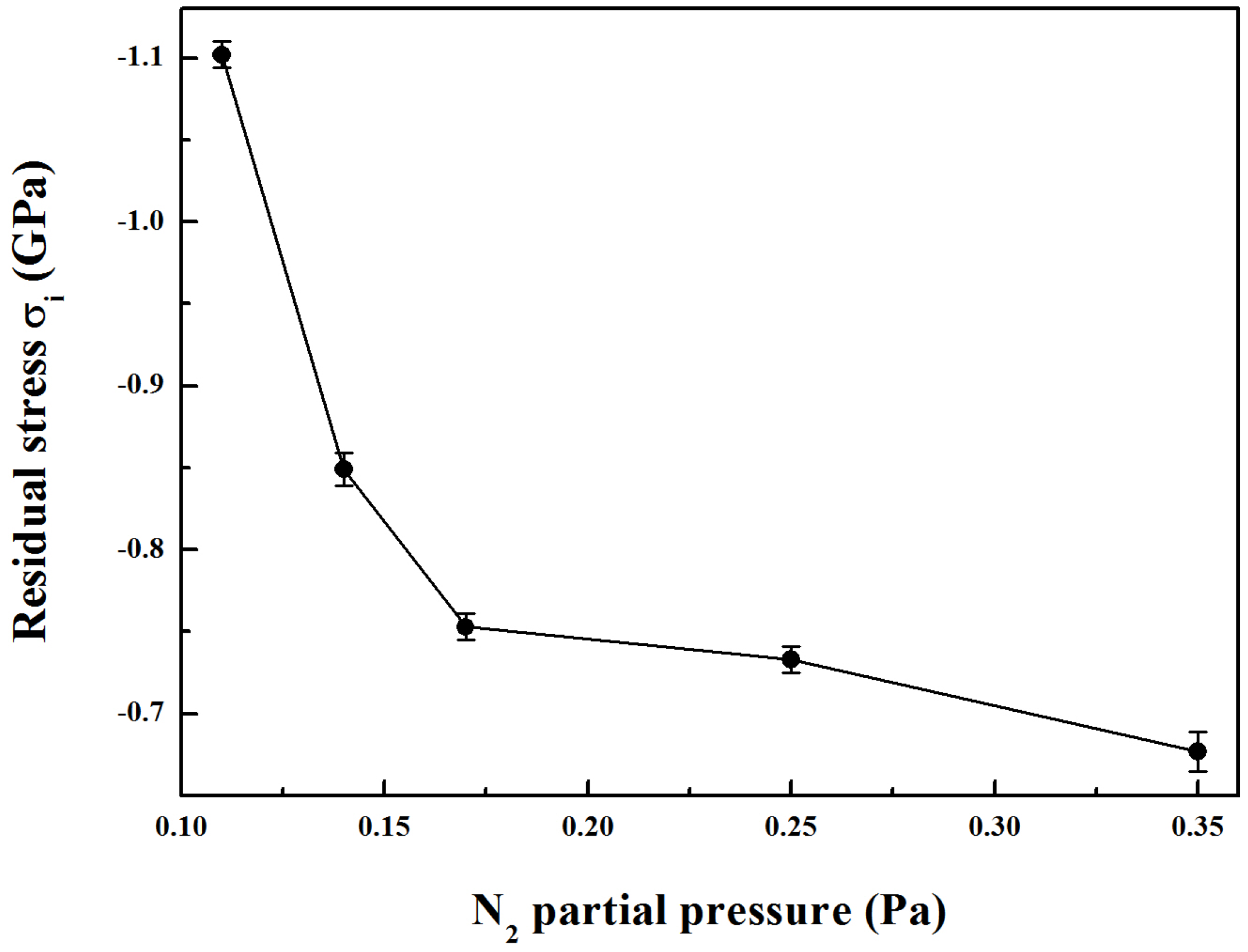
Figure 5 presents the residual stress of Mo-Cu-V-N composite coatings as a function of the N2 partial pressure. It can be clearly seen that the compressive residual stress of the coatings decreased first from −1.10 GPa to −0.84 GPa with an increase in the N2 partial pressure from 0.11 to 0.14 Pa, which would be mainly due to the initial increase of Cu content in the coatings. The decrease in residual stress would be due to the presence of a compliant copper phase in the coatings [14]. As the N2 partial pressure was further increased to 0.35 Pa, a slowly decreasing compressive residual stress was observed down to −0.68 GPa. As the columnar microstructure became coarser at higher N2 partial pressures, the residual stress induced by sputtering could be released, resulting in a decrease of the compressive residual stress. Meanwhile, the decrease in the intrinsic compressive residual stress could be associated with the absence of a significant number of high-energy ions bombarding the growing film during deposition process at higher nitrogen partial pressures [30].
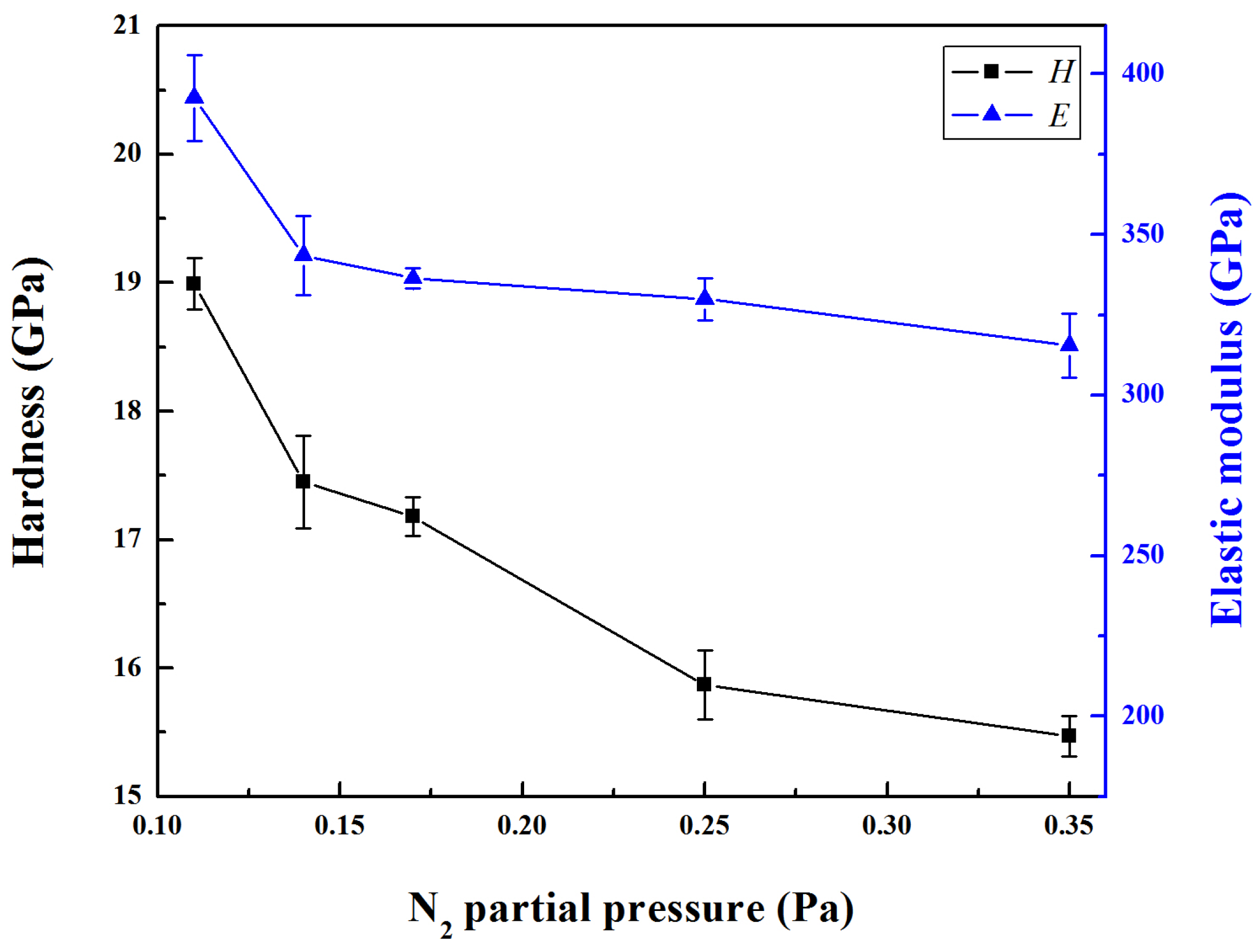
The hardness and elastic modulus of Mo-Cu-V-N composite coatings as a function of N2 partial pressure is shown in Figure 6. Both the hardness and modulus showed the same trend. With increasing the N2 partial pressure from 0.11 to 0.35 Pa, the hardness and elastic modulus decreased from 19.0 GPa and 393 GPa to 15.5 GPa and 316 GPa, respectively. Therefore, the hardness exhibited a decrease instead of rebound as the N2 partial pressure increased to 0.35 Pa when compared to the Mo-Cu-V-N coatings in previous studies [20]. The reduction of the hardness at higher copper concentrations was reported to be related with grain boundary sliding due to the weak interface of nc-Mo2N/Cu or large amount of Cu segregation [31]. In this present work, the compressive residual stress and microstructure of the coatings mainly determined the variation tendency of the hardness of the coatings with N2 partial pressure. The decrease in hardness could be explained as follows: (1) At higher partial pressures, the decrease in compressive residual stress would play an important role in the hardness of coatings. It is generally observed that a high compressive residual stress usually accounts for high hardness values, the decrease in hardness would be due to the relaxation of the compressive residual stress [32]. (2) The coarser columnar microstructure at high Cu content can also be assumed to contribute to the lower hardness as well as to the lower elastic modulus. Moreover, the preferred orientation (200) peak was significantly broader at higher nitrogen partial pressures indicating grain refinement, which was not the main influence factor of the hardness of Mo-Cu-V-N composite coatings with high Cu content.

3.2. Tribological Properties

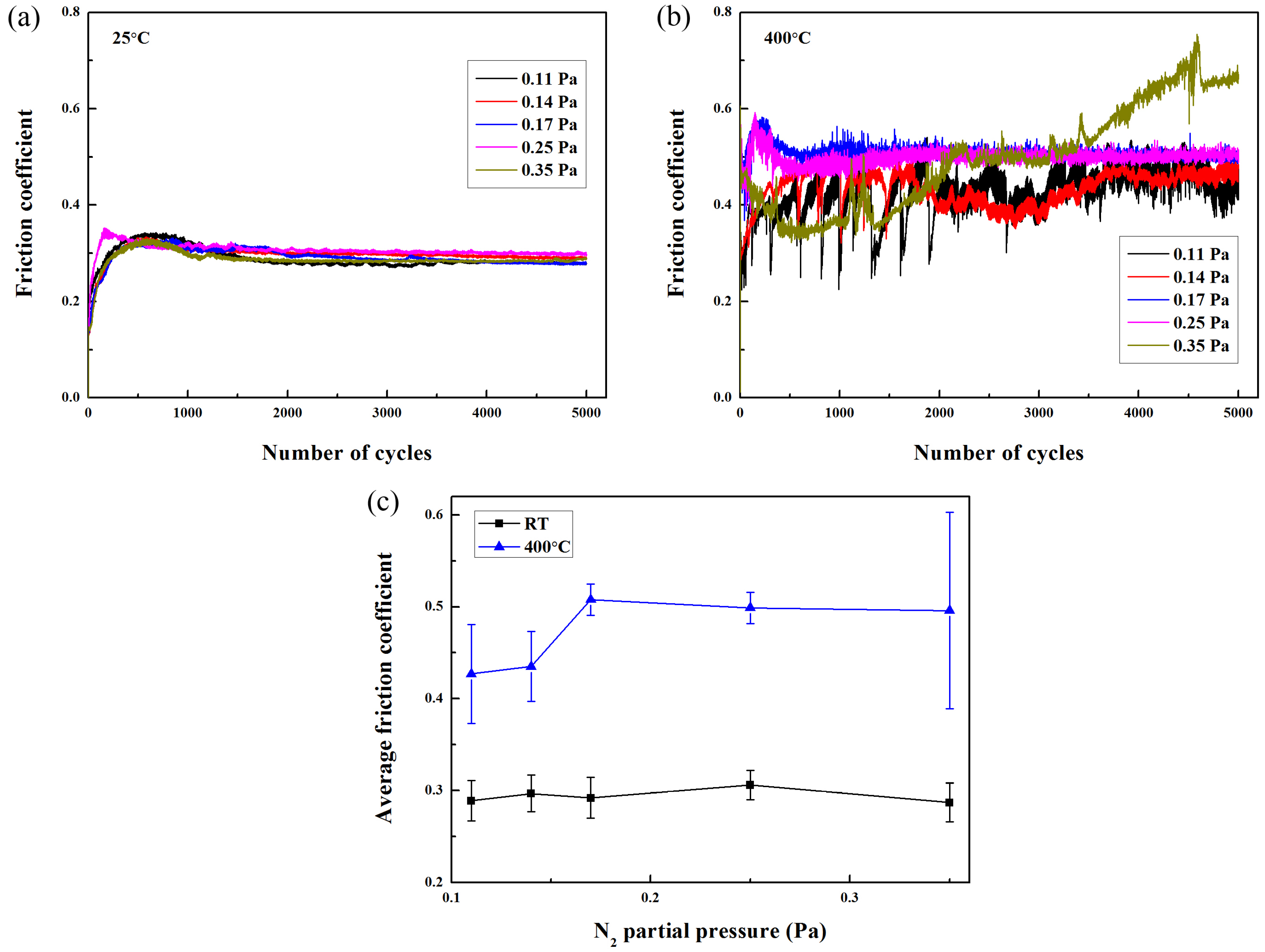
Figure 7 reveals the friction coefficient curves of Mo-Cu-V-N composite coatings after tribological tests at 25 °C and 400 °C, respectively. In a similar ball-on-disc dry sliding wear of a sputtered nitride coating, the running-in friction would be attributed to the initial wear particle generation and the subsequent formation of a tribofilm [33]. It was found that all the friction coefficient curves rapidly increased in the initial running-in phase, and reached steady-state after sliding about 1000 cycles at 25 °C. However, the obvious fluctuation was observed in the friction curve when the wear temperature was increased up to 400 °C, especially for the Mo-Cu-V-N composite coating deposited at the N2 partial pressure of 0.35 Pa. If a stable oxide layer were not present in the wear track, the friction coefficient curve should exhibit significant fluctuations associated to the formation and loss of the oxides that are expected to form under these experimental conditions [34]. As shown in Figure 7c, the average friction coefficient varied in the small range of 0.29–0.31 when sliding at 25 °C. When the wear temperature was increased up to 400 °C, the average friction coefficient first increased from 0.43 to 0.51 as the N2 partial pressure increased from 0.11 to 0.17 Pa, and then remained almost constant.
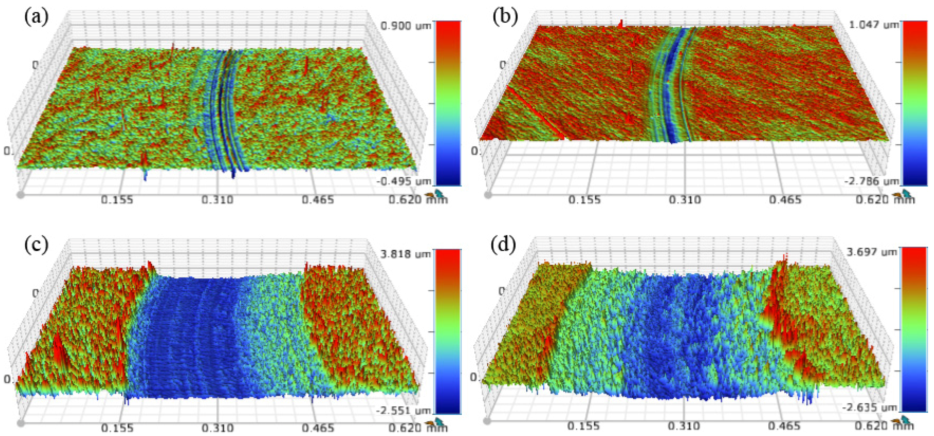
A comparison of three-dimensional morphologies of the wear tracks after the coatings were tested at different temperatures is shown in Figure 8. Grooves with different depths and widths were observed on the wear tracks of the Mo-Cu-V-N composite coatings after tribological tests at different temperatures. When sliding at 25 °C, it can be clearly seen that the wear tracks were much narrower and shallower, and some “plow furrow” formed along the counterpart sliding direction in the area of wear tracks, indicating that abrasive wear occurred at 25 °C. In addition, the wear track widths increased sharply with the increase of wear temperature and N2 partial pressure at the high temperature of 400 °C (Figure 8c,d), indicating the decrease of wear resistant. 
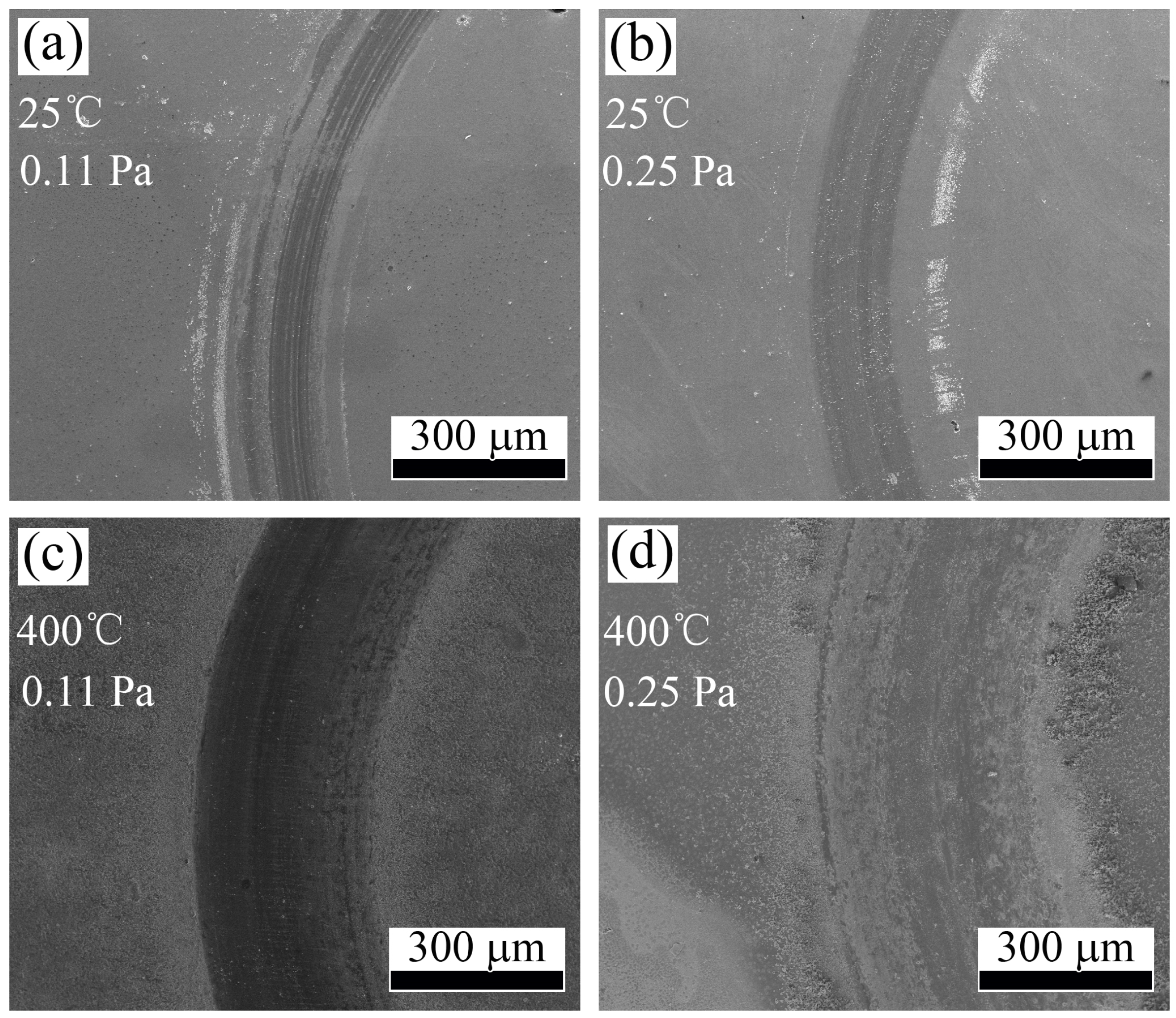
Figure 9 displays the surface images of the wear tracks of Mo-Cu-V-N composite coatings after tribological tests. It was found that the surfaces of the wear tracks were relatively smooth when sliding at 25 °C, and some wear debris accumulated at the boundary of the wear tracks. However, the surfaces of the wear tracks became rougher when the wear temperature was increased up to 400 °C, as shown in Figure 9c,d. Moreover, some wear particles also appeared on the surfaces of wear tracks, which could account for the increase of friction coefficient at high temperatures. It was reported that the wear particles generated were entrapped subsequently in the sliding contact, causing three-body sliding/rolling abrasive wear of the coating surface and fracturing of the wear particles themselves [35].
To analyze the wear mechanism of the Mo-Cu-V-N composite coatings at different temperatures and N2 partial pressures, the chemical composition of the wear tracks on the worn surfaces were determined by EDS analysis. As shown in Table 2, the EDS analysis indicated that some O element was detected in the wear tracks at 25 °C, which was in the small range of 11.5–13.8 at.%, indicating that a tribo-oxidation phenomenon occurred during the sliding test. As the wear temperature was increased up to 400 °C, the O content in the wear track was increased up to 56.0–61.8 at.%, while the N content in the wear track decreased sharply to 9.4–12.2 at.%, indicating that the Mo-Cu-V-N composite coatings had been oxidized severely. The weak bonds between molybdenum and nitrogen easily broke at elevated temperatures, which would lead to the loss of nitrogen and pronounced oxidation [36]. Therefore, the oxidation wear became the main wear mechanism when sliding at the high temperature of 400 °C. In addition, it could be found that less O contents and more N contents were detected in the wear tracks with the increase of N2 partial pressure, which could lead to better lubrications at lower nitrogen partial pressures. This is similar to an investigation by Wang et al. which showed the MoNx coating with higher N content would be much more difficult to be oxidized in air [28].
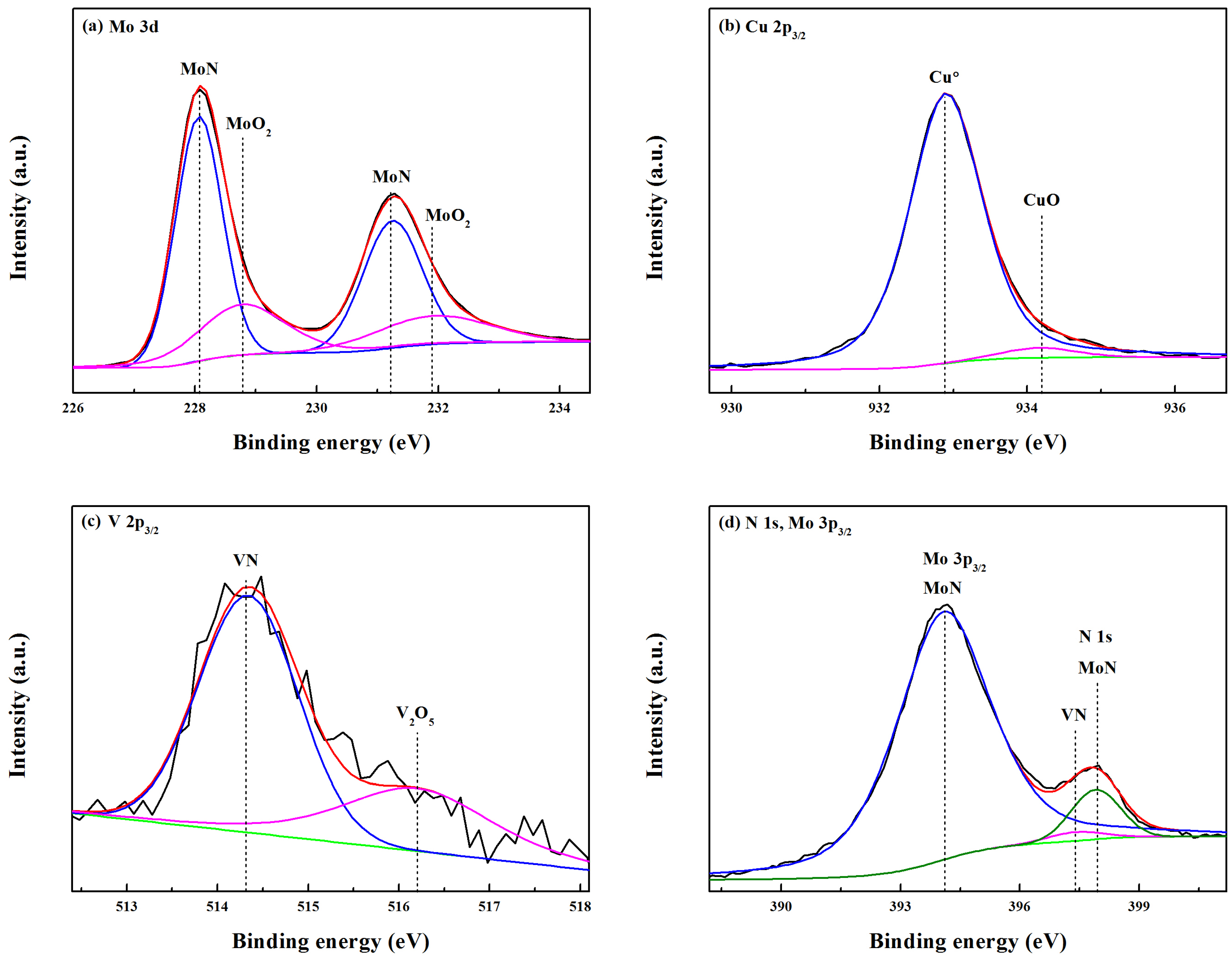
After the tribological tests at 25 °C and 400 °C, the XPS analysis was employed on the area A and B in the wear tracks (Figure 9a,c) to determine the chemical bonding states of the oxide scales. As shown in Figure 10, the asymmetric Mo 3d peaks consisted of two main peaks at binding energies (BE) of 228.1 eV and 231.2 eV, and two smaller peaks at binding energies of 228.8 eV and 231.9 eV, corresponding to the Mo 3d5/2 and Mo 3d3/2 electrons in the MoN and MoO2, respectively. Therefore, the Mo 3d, as well as Cu 2p, and N 1s XPS core level spectra of the worn surfaces showed similar results to the XPS analysis of the as-deposited Mo-Cu-V-N coating (as shown in Figure 3). However, the fitted V 2p3/2 spectrum with two peaks centered at binding energies of 514.3 eV and 516.2 eV, which corresponded to VN and V2O5, respectively (Figure 10c). It indicated that the vanadium nitride phase existed in the Mo-Cu-V-N coatings was partially oxidized to form the lubricious oxide of V2O5. 
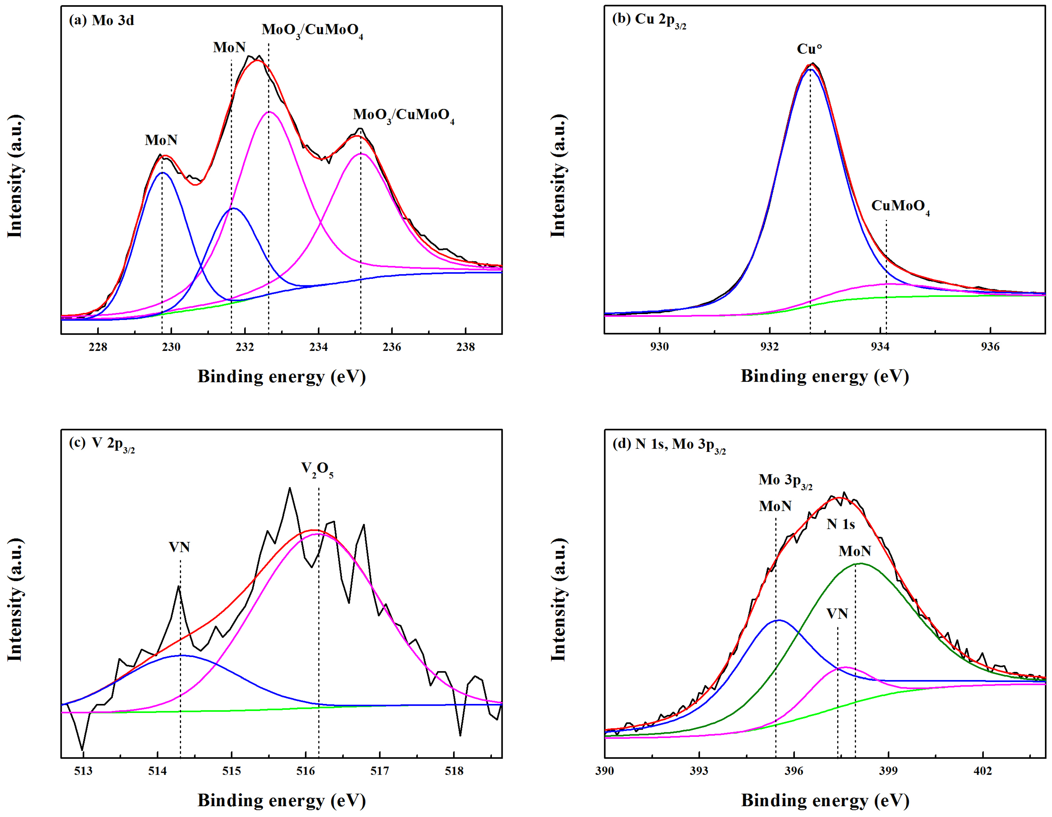
Figure 11 shows the fitted XPS spectra of the wear track of Mo-Cu-V-N composite coating after tribological test at 400 °C. As shown in Figure 11a, the Mo 3d peaks shifted towards high binding energies and contain two possible components at the binding energies of 229.7/231.6 eV and 232.6/235.1 eV, originating from Mo 3d5/2 and Mo 3d3/2 electrons in MoN and MoO3/CuMoO4, respectively. It was difficult to distinguish the MoO3 (232.5 ± 0.3 eV) and CuMoO4 (232.7 ± 0.3 eV) species by Mo 3d3/2 spectrum because the peak positions are too close [21]. In Figure 11b, the fitted Cu 2p3/2 spectrum showed two components at 932.7 eV and 934.1 eV, which can be assigned to the spectra of Cu0 and CuMoO4, respectively. It was reported that CuMoO4 possesses better self-lubricating behavior than MoO3 due to the high difference of ionic potentials existing between MoO3 and CuO (8.2 − 2.8 = 5.4) [37]. Therefore, by considering both the Mo 3d spectrum and Cu 2p3/2 spectrum in Figure 11a,b, it can be assumed that mainly MoO3 oxides formed in the wear track for Mo-Cu-V-N composite coating. In addition, it can be clearly seen that mainly MoO3/CuMoO4 and minor MoN species were found in the XPS peaks when the wear temperature was increased up to 400 °C, which could be due to the loss of nitrogen and pronounced oxidation at high temperatures for the Mo-Cu-V-N composite coatings. It was in accordance with the rapid increase of O content in the wear tracks as shown in Table 2. Similar results were also found for the VN and V2O5 species in the V 2p3/2 XPS peak as seen in Figure 11c. Meanwhile, the Mo 3p3/2 peak shifted towards high binding energies and the peak intensity decreased sharply when the wear temperature was increased up to 400 °C (Figure 11d), which was in accordance with the decrease of Mo content in the wear track.
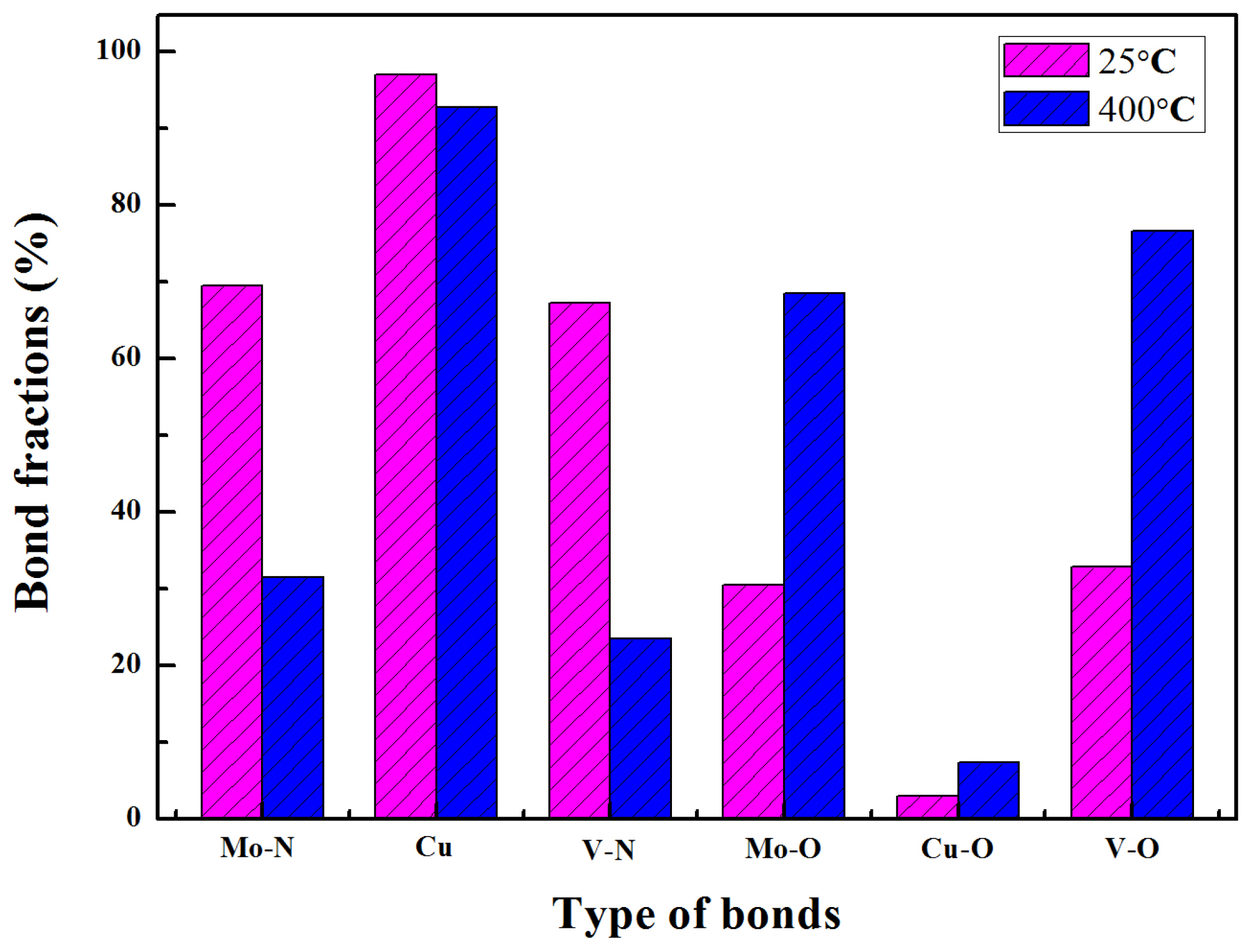
To further investigate the chemical structure evolution process induced by the increased in wear temperature, the bond fractions were calculated based on the corresponding peak areas of the fitted XPS peaks. Figure 12 shows the Mo-N, Mo-O, Cu, Cu-O, V-N, and V-O bond fractions of Mo-Cu-V-N composite coatings deposited at the N2 partial pressure of 0.11 Pa. The Mo-O, Cu-O, and V-O bonds were found in the Mo-Cu-V-N coating after the friction test conducted at 25 °C, which would be due to the tribo-oxidation phenomenon that occurred during the sliding test. It can be seen that the Mo-N, Cu, and V-N bond fractions were 69.5%, 97.0%, and 67.2%, respectively, which are higher than those of the oxide bonds. It indicated that the Mo-Cu-V-N composite coating had been oxidized slightly during sliding at room temperature, which was in accordance with the EDS analysis as shown in Table 2. When the wear temperature was further increased to 400 °C, the Mo-N, Cu, and V-N bond fractions decreased to 31.5%, 92.7%, and 23.4%, while the Mo-O, Cu-O, and V-O bond fractions increased up to 68.5%, 7.3%, and 76.6%, respectively. It indicated that the Mo-Cu-V-N composite coatings had been oxidized severely during sliding at the high temperature of 400 °C.
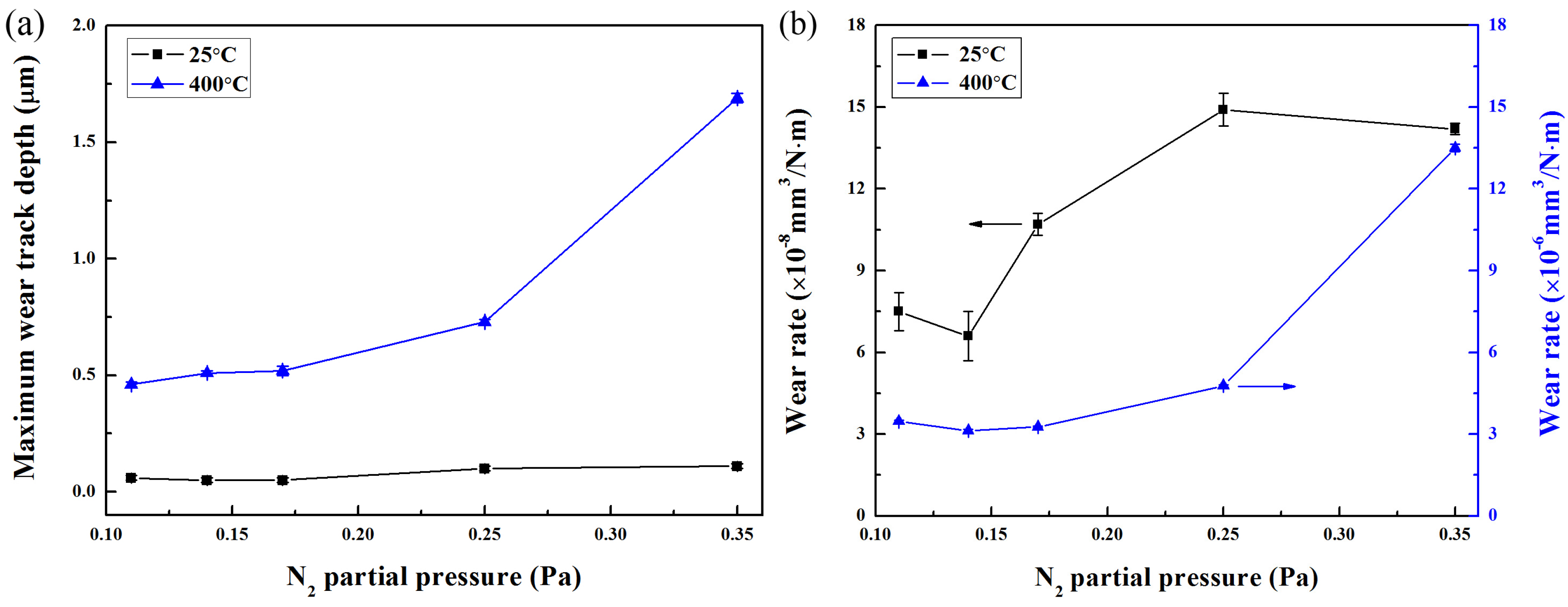
Figure 13a depicts the maximum wear track depth with respect to the wear temperature and N2 partial pressure. A relatively low wear track depth in the small range of 0.05–0.11 μm was achieved after the tribological test at 25 °C. However, when the wear temperature was increased up to 400 °C, the maximum wear track depth increased sharply from 0.46 to 1.69 μm while the N2 partial pressure increased from 0.11 to 0.35 Pa. It can be seen that the maximum wear track depths were less than the coating thickness, indicating that all the coatings were not worn out to failure even at the high temperature of 400 °C. The different wear track depths of the coatings could be due to the different friction and wear behaviors, which could directly influence the wear rate of the coatings. As shown in Figure 13b, after the tribological test at 25 °C, the wear rate of Mo-Cu-V-N composite coatings first decreased slightly from 7.5 × 10⁻⁸ to 6.6 × 10⁻⁸ mm3/N·m by increasing the N2 partial pressure from 0.11 to 0.14 Pa, which would be due to the initial increase of Cu content in the coatings and the release of residual stress. The wear rate was correlated to the adhesion energy, which was directly related to the residual stress and ultimately, the initial copper content [14]. When the N2 partial pressure further increased to 0.35 Pa, the wear rate followed by an increase to 14.9 × 10⁻⁸ mm3/N·m, which could be mainly due to the decrease of mechanical properties at higher nitrogen partial pressures. When compared to the Mo-Cu-V-N coatings with low Cu content [20], a much lower wear rate of 10−8 mm3/N·m was achieved in this work, which was similar to the wear rate of the Al-DLC films deposited by a hybrid beams system comprising an anode-layer ion source and a magnetron sputtering unit [38]. The typical wear rate values for solid lubricants with moderate wear resistance were between 10−7 and 10−5 mm3/N·m [14,39]. Therefore, the excellent tribological properties could be attributed to the mixed lubricious oxides of MoO2, CuO and V2O5 formed during tribo-oxidation, which usually lead to lower friction coefficients and better wear resistance [15]. When the wear temperature was increased up to 400 °C, despite of the forming of lubricious oxides of MoO3/CuMoO4 and V2O5, the high wear rate increased from 3.1 × 10⁻⁶ to 13.5 × 10⁻⁶ mm3/N·m with increasing the N2 partial pressure, which was higher two orders of magnitude than of at 25 °C. It could be mainly due to the loss of nitrogen and pronounced oxidation at high temperatures, which led the wear mechanism to be transformed from mild oxidation wear to severe oxidation wear.

4. Conclusions

In this study, the microstructure, mechanical properties and tribological properties of Mo-Cu-V-N composite coatings with high Cu content of ~18 at.% deposited at various N2 partial pressures were investigated. All the Mo-Cu-V-N composite coatings revealed FCC B1-MoN phase with a strong (200) preferred orientation, and the peak intensity decreased gradually with the increase of N2 partial pressure, and Cu was found to exist as metallic species in the Mo-Cu-V-N coatings. As the N2 partial pressure increased from 0.11 to 0.35 Pa, the columnar microstructure became much coarser, which resulted in decrease of residual stress and hardness at high Cu content. The Mo-Cu-V-N composite coatings with high Cu content exhibited a relatively low wear rate of 10−8 mm3/N·m at 25 °C. It was believed to be attributed to the mixed lubricious oxides of MoO2, CuO and V2O5 formed during tribo-oxidation. As the wear temperature was increased up to 400 °C, the wear rate increased sharply up to 10−6 mm3/N·m despite of the formation of lubricious oxides of MoO3/CuMoO4 and V2O5, which was two orders of magnitude higher than that of at 25 °C. It could be due to the loss of nitrogen and pronounced oxidation at high temperature, which led to the transformation of the wear mechanism from mild oxidation wear to severe oxidation wear.

Acknowledgments

The work was supported in part by the projects of the National Natural Science Foundation of China (51522502, 51275095), China Postdoctoral Science Foundation funded project (2016M600641) and Guangdong Natural Science Funds (2014A030311002, 2016A050502056).

Author Contributions

Qimin Wang conceived and designed the experiments; Rui Wang and Xing Zhong performed the experiments; Haijuan Mei analyzed the data; Qimin Wang contributed reagents/materials/ analysis tools; Wei Dai and Haijuan Mei wrote the paper.

Conflicts of Interest

The authors declare no conflict of interest. The founding sponsors had no role in the design of the study; in the collection, analyses, or interpretation of data; in the writing of the manuscript, and in the decision to publish the results.

References

  1. Münz, W.D. TiAlN Films: An Alternative to TiN Coatings. J. Vac. Sci. Technol. A 1986, 4, 2717–2725. [Google Scholar] [CrossRef]
  2. PalDey, S.; Deevi, S.C. Single layer and multilayer wear resistant coatings of (Ti,Al)N: A review. Mater. Sci. Eng. A 2003, 342, 58–79. [Google Scholar] [CrossRef]
  3. Gilmore, R.; Baker, M.A.; Gibson, P.N.; Gissler, W.; Stoiber, M.; Losbichler, P.; Mitterer, C. Low-friction TiN-MoS2 coatings produced by dc magnetron co-deposition. Surf. Coat. Technol. 1998, 108–109, 345–351. [Google Scholar] [CrossRef]
  4. Stoiber, M.; Badisch, E.; Lugmair, C.; Mitterer, C. Low-friction TiN coatings deposited by PACVD. Surf. Coat. Technol. 2003, 163–164, 451–456. [Google Scholar] [CrossRef]
  5. Erdemir, A.; Halter, M.; Fenske, G.R. Preparation of ultralow-friction surface films on vanadium diboride. Wear 1997, 205, 236–239. [Google Scholar] [CrossRef]
  6. Badisch, E.; Fontalvo, G.A.; Stoiber, M.; Mitterer, C. Tribological behavior of PACVD TiN coatings in the temperature range up to 500 °C. Surf. Coat. Technol. 2003, 163–164, 585–590. [Google Scholar] [CrossRef]
  7. Storz, O.; Gasthuber, H.; Woydt, M. Tribological properties of thermal-sprayed Magnéli-type coatings with different stoichiometries (TinO2n−1). Surf. Coat. Technol. 2001, 140, 76–81. [Google Scholar] [CrossRef]
  8. Heo, S.J.; Kim, K.H.; Kang, M.C.; Suh, J.H.; Park, C.G. Syntheses and mechanical properties of Mo–Si–N coatings by a hybrid coating system. Surf. Coat. Technol. 2006, 201, 4180–4184. [Google Scholar] [CrossRef]
  9. Suszko, T.; Gulbinski, W.; Jagielski, J. The role of surface oxidation in friction processes on molybdenum nitride thin films. Surf. Coat. Technol. 2005, 194, 319–324. [Google Scholar] [CrossRef]
  10. Lyo, I.W.; Ahn, H.S.; Lim, D.S. Microstructure and tribological properties of plasma-sprayed chromium oxide–molybdenum oxide composite coatings. Surf. Coat. Technol. 2003, 163–164, 413–421. [Google Scholar] [CrossRef]
  11. Gassner, G.; Mayrhofer, P.H.; Kutschej, K.; Mitterer, C.; Kathrein, M. A new low Friction concept for high temperatures: Lubricious oxide formation on sputtered VN coatings. Tribol. Lett. 2004, 17, 751–756. [Google Scholar] [CrossRef]
  12. Fateh, N.; Fontalvo, G.A.; Gassner, G.; Mitterer, C. Influence of high-temperature oxide formation on the tribological behaviour of TiN and VN coatings. Wear 2007, 262, 1152–1158. [Google Scholar] [CrossRef]
  13. Franz, R.; Mitterer, C. Vanadium containing self-adaptive low-friction hard coatings for high-temperature applications: A review. Surf. Coat. Technol. 2013, 228, 1–13. [Google Scholar] [CrossRef]
  14. Pappacena, K.E.; Singh, D.; Ajayi, O.O.; Routbort, J.L.; Erilymaz, O.L.; Demas, N.G.; Chen, G. Residual stresses, interfacial adhesion and tribological properties of MoN/Cu composite coatings. Wear 2012, 278, 62–70. [Google Scholar] [CrossRef]
  15. Kim, J.N.; Park, S.; Kim, T.; Lee, J.J. Structure and mechanical properties of Mo–N/Cu films produced by inductively coupled plasma reactive sputtering. Thin Solid Films 2011, 519, 6876–6880. [Google Scholar] [CrossRef]
  16. Alami, J.; Bolz, S.; Sarakinos, K. High power pulsed magnetron sputtering: Fundamentals and applications. J. Alloy Compd. 2009, 483, 530–534. [Google Scholar] [CrossRef]
  17. Shi, Y.J.; Pan, F.S.; Bao, M.D.; Yang, Z.L.; Wang, L. Effect of N2 flow rate on structure and property of ZrNbAlNx multilayer films deposited by magnetron sputtering. J. Alloy Compd. 2013, 559, 196–202. [Google Scholar] [CrossRef]
  18. Wang, X.; Wang, L.S.; Qi, Z.B.; Yue, G.H.; Chen, Y.Z.; Wang, Z.C.; Peng, D.L. Investigation on the structure and properties of AlxCr1-xN coatings deposited by reactive magnetron co-sputtering. J. Alloy. Compd. 2010, 502, 243–249. [Google Scholar] [CrossRef]
  19. Lin, J.; Wu, Z.L.; Zhang, X.H.; Mishra, B.; Moore, J.J.; Sproul, W.D. A comparative study of CrNx coatings Synthesized by dc and pulsed dc magnetron sputtering. Thin Solid Films 2009, 517, 1887–1894. [Google Scholar] [CrossRef]
  20. Mei, H.J.; Zhao, S.S.; Wu, Z.T.; Dai, W.; Wang, Q.M. Effect of nitrogen partial pressure on microstructure and mechanical properties of Mo-Cu-V-N composite coatings deposited by HIPIMS. Surf. Coat. Technol. 2017, 329, 68–76. [Google Scholar] [CrossRef]
  21. Shin, J.H.; Wang, Q.M.; Kim, K.H. Microstructural evolution and tribological behavior of Mo-Cu-N coatings as a function of Cu content. Mater. Chem. Phys. 2011, 130, 870–879. [Google Scholar] [CrossRef]
  22. Gulbiński, W.; Suszko, T.; Sienicki, W.; Warcholiński, B. Tribological properties of silver-and copper-doped transition metal oxide coatings. Wear 2003, 254, 129–135. [Google Scholar] [CrossRef]
  23. Stoney, G.G. The tension of metallic films deposited by electrolysis. Proc. R. Soc. Lond. A Mater. 1909, 82, 172–175. [Google Scholar] [CrossRef]
  24. Christie, D.J. Target material pathways model for high power pulsed magnetron sputtering. J. Vac. Sci. Technol. A 2005, 23, 330–335. [Google Scholar] [CrossRef]
  25. Pelleg, J.; Zevin, L.Z.; Lungo, S. Reactive-sputter-deposited TiN films on glass substrates. Thin Solid Films 1991, 197, 117–128. [Google Scholar] [CrossRef]
  26. Ihara, H.; Kimura, Y.; Senzaki, K.; Kezuka, H.; Hirabayashi, M. Electronic structures of B1 MoN, fcc Mo/sub 2/N, and hexagonal MoN. Phys. Rev. B 1985, 31, 3177–3178. [Google Scholar] [CrossRef]
  27. Kim, G.T.; Park, T.K.; Chung, H.; Kim, Y.T.; Kwon, M.H.; Choi, J.G. Growth and characterization of chloronitroaniline crystals for optical parametric oscillators: I. XPS study of Mo-based compounds. Appl. Surf. Sci. 1999, 152, 35–43. [Google Scholar] [CrossRef]
  28. Wang, T.; Zhang, G.J.; Ren, S.; Jiang, B.L. Effect of nitrogen flow rate on structure and properties of MoNx coatings deposited by facing target sputtering. J. Alloy. Compd. 2017, 701, 1–8. [Google Scholar] [CrossRef]
  29. Lin, M.C.; Chang, L.-S.; Lin, H.C. Effects of nitrogen partial pressure on titanium oxynitride films deposited by reactive RF magnetron sputtering onto PET substrates. Surf. Coat. Technol. 2008, 202, 5440–5443. [Google Scholar] [CrossRef]
  30. Hones, P.; Martin, N.; Regula, M.; Lévy, F. Structural and mechanical properties of chromium nitride, molybdenum nitride, and tungsten nitride thin films. J. Phys. D Appl. Phys. 2003, 36, 1023–1029. [Google Scholar] [CrossRef]
  31. Zeman, P.; Cerstvý, R.; Mayrhofer, P.H.; Mitterter, C.; Musil, J. Structure and properties of hard and superhard Zr-Cu-N nanocomposite coatings. Mater. Sci. Eng. A 2000, 289, 189–197. [Google Scholar] [CrossRef]
  32. Wan, X.S.; Zhao, S.S.; Yang, Y.; Gong, J.; Sun, C. Effects of nitrogen pressure and pulse bias voltage on the properties of Cr-N coatings deposited by arc ion plating. Surf. Coat. Technol. 2010, 204, 1800–1810. [Google Scholar] [CrossRef]
  33. Luo, Q. Origin of friction in running-in sliding wear of nitride coatings. Tribol. Lett. 2010, 37, 529–539. [Google Scholar] [CrossRef]
  34. Staia, M.H.; Pérez-Delgado, Y.; Sanchez, C.; Castro, A.; Bourhis, E.L.; Puchi-Cabrera, E.S. Hardness properties and high-temperature wear behaviour of nitrided AISI D2 tool steel, prior and after PAPVD coating. Wear 2009, 267, 1452–1461. [Google Scholar] [CrossRef]
  35. Luo, Q. Temperature dependent friction and wear of magnetron sputtered coating TiAlN/VN. Wear 2011, 271, 2058–2066. [Google Scholar] [CrossRef]
  36. Gassner, G.; Mayrhofer, P.H.; Kutschej, K.; Mitterer, C.; Kathrein, M. Magnéli phase formation of PVD Mo-N and W-N coatings. Surf. Coat. Technol. 2006, 201, 3335–3341. [Google Scholar] [CrossRef]
  37. Öztürk, A.; Ezirmik, K.V.; Kazmanlı, K.; Ürgen, M.; Eryılmaz, O.L.; Erdemir, A. Comparative tribological behaviors of TiN-, CrN- and MoN-Cu nanocomposite coatings. Tribol. Int. 2008, 41, 49–59. [Google Scholar] [CrossRef]
  38. Dai, W.; Wang, A.Y. Deposition and properties of Al-containing diamond-like carbon films by a hybrid ion beam sources. J. Alloy. Compd. 2011, 509, 4626–4631. [Google Scholar] [CrossRef]
  39. Muratore, C.; Voevodin, A.A. Chameleon Coatings: Adaptive surfaces to reduce friction and wear in extreme environments. Annu. Rev. Mater. Res. 2009, 39, 297–324. [Google Scholar] [CrossRef]
Figure 1. Chemical composition of Mo-Cu-V-N composite coatings.
Coatings 08 00024 g001
Figure 2. (a) X-ray diffraction patterns and (b) lattice parameters of Mo-Cu-V-N coatings as a function of N2 partial pressure.
Coatings 08 00024 g002
Figure 3. Fitted XPS spectra of Mo-Cu-V-N coating deposited at the N2 partial pressure of 0.11 Pa: (a) Mo 3d, (b) Cu 2p3/2, (c) V 2p3/2, and (d) N 1s, Mo 3p3/2.
Coatings 08 00024 g003
Figure 4. Cross-sectional SEM micrographs of Mo-Cu-V-N composite coatings deposited at various N2 partial pressures: (a) 0.11 Pa, (b) 0.14 Pa, (c) 0.17 Pa, (d) 0.25 Pa and (e) 0.35 Pa.
Coatings 08 00024 g004
Figure 5. Residual stress of Mo-Cu-V-N coatings as a function of N2 partial pressure.
Coatings 08 00024 g005
Figure 6. Hardness and elastic modulus of Mo-Cu-V-N coatings as a function of N2 partial pressure.
Coatings 08 00024 g006
Figure 7. Friction coefficient curves of Mo-Cu-V-N coatings tested at (a) 25 °C and (b) 400 °C; (c) the average friction coefficient as a function of N2 partial pressure.
Coatings 08 00024 g007
Figure 8. Three-dimensional morphologies of the wear tracks: (a) 25 °C, 0.11 Pa; (b) 25 °C, 0.25 Pa; (c) 400 °C, 0.11 Pa and (d) 400 °C, 0.25 Pa.
Coatings 08 00024 g008
Figure 9. SEM images of the wear tracks after tribological tests: (a) 25 °C, 0.11 Pa; (b) 25 °C, 0.25 Pa; (c) 400 °C, 0.11 Pa and (d) 400 °C, 0.25 Pa.
Coatings 08 00024 g009
Figure 10. Fitted XPS spectra of the wear track of Mo-Cu-V-N composite coating after tribological test at 25 °C: (a) Mo 3d, (b) Cu 2p3/2, (c) V 2p3/2, and (d) N 1s, Mo 3p3/2.
Coatings 08 00024 g010
Figure 11. Fitted XPS spectra of the wear track of Mo-Cu-V-N composite coating after tribological test at 400 °C: (a) Mo 3d, (b) Cu 2p3/2, (c) V 2p3/2, and (d) N 1s, Mo 3p3/2.
Coatings 08 00024 g011
Figure 12. The Mo-N, Mo-O, Cu, Cu-O, V-N and V-O bond fractions of Mo-Cu-V-N composite coating after tribological tests at different temperatures.
Coatings 08 00024 g012
Figure 13. (a) Maximum wear track depth and (b) wear rate of Mo-Cu-V-N composite coatings as a function of N2 partial pressure.
Coatings 08 00024 g013
Table 1. The detail parameters of the experiment.
ProcessParametersValues
Ar glow dischargeBias voltage (V)–1000
Ar flow rate (sccm)300
Time (min)15
Ion etchingBias voltage (V)800
Cathode current (A)100
Time (min)5
Coating depositionWorking pressure (Pa)0.7
N2 partial pressure (Pa)0.11, 0.14, 0.17, 0.25, 0.35
Bias voltage (V)–100
Sputtering power (kW)1.0
Pulse width (us)150
Frequency (Hz)400
Duty cycle6%
Time (min)180
Table 2. Chemical composition of the wear tracks after tribological tests at different temperatures.
TemperatureN2 Partial PressureChemical Composition (at.%)
MoCuVNO
25 °C0.11 Pa36.2014.602.2533.1813.77
0.25 Pa33.4314.552.5538.0011.48
400 °C0.11 Pa20.826.391.689.3561.77
0.25 Pa22.268.011.4512.2456.03

