1. Introduction
Diamond films have been widely studied in many fields to improve the physical hardness of existing materials, including end mills and tool steels, because of their excellent hardness and various advantages [
1]. Many deposition methods are used for diamond coatings, with the most widely used method being hot filament chemical vapor deposition (HF-CVD) [
2,
3].
As noted, diamonds have been very actively studied in many fields since they have very good properties [
4,
5]. However, diamond films are typically difficult to deposit, since they often require suitable deposition conditions regarding temperature and pressure.
The most important factor for producing high-quality diamond films is the temperature distribution between the filament and susceptor. In addition, the temperature distribution affects concentrations of chemical species, which also represent an important factor in the production of high quality diamond films [
6]. Obtaining information on this temperature distribution is not easily achieved using experimental methods, since the temperature gradient between the filament and susceptor as well as the temperature near the filament is too high. At the same time, a more complicated and bigger HF-CVD system is needed to produce large sized diamond films with high quality [
7,
8]. To address this problem, a numerical approach is needed to determine the mechanism of diamond deposition with respect to temperature. Many studies have conducted numerical simulations of the HF-CVD process [
9,
10,
11].
In this simulation, the temperature distribution was calculated based on the input power at a fixed pressure of 4000 Pa and a fixed filament distance of 10 mm from the substrate. The simulation results were analyzed to predict the appropriate power for diamond deposition with high growth rate and quality. The simulation was conducted using the commercial computational fluid dynamic (CFD) code, FLUENT (17.0), in the ANSYS software (17.0). Radiative heat transfer also had to be considered in this simulation since the HF-CVD system has a very hot filament and is operated at low pressure [
12]. The discrete ordinate (DO) model in FLUENT was used to consider the radiative heat transfer.
In this experiment, the temperature and pressure used in the HF-CVD system were determined based on the results of the computational analysis, and then an actual experiment was conducted to observe the change in temperature, and therefore the diamond coating, depending on the input power. A two-color pyrometer was used to obtain measurements to compare with and verify the calculated values from the numerical method.
2. Numerical and Experimental Details
2.1. Numerical Calculation Method
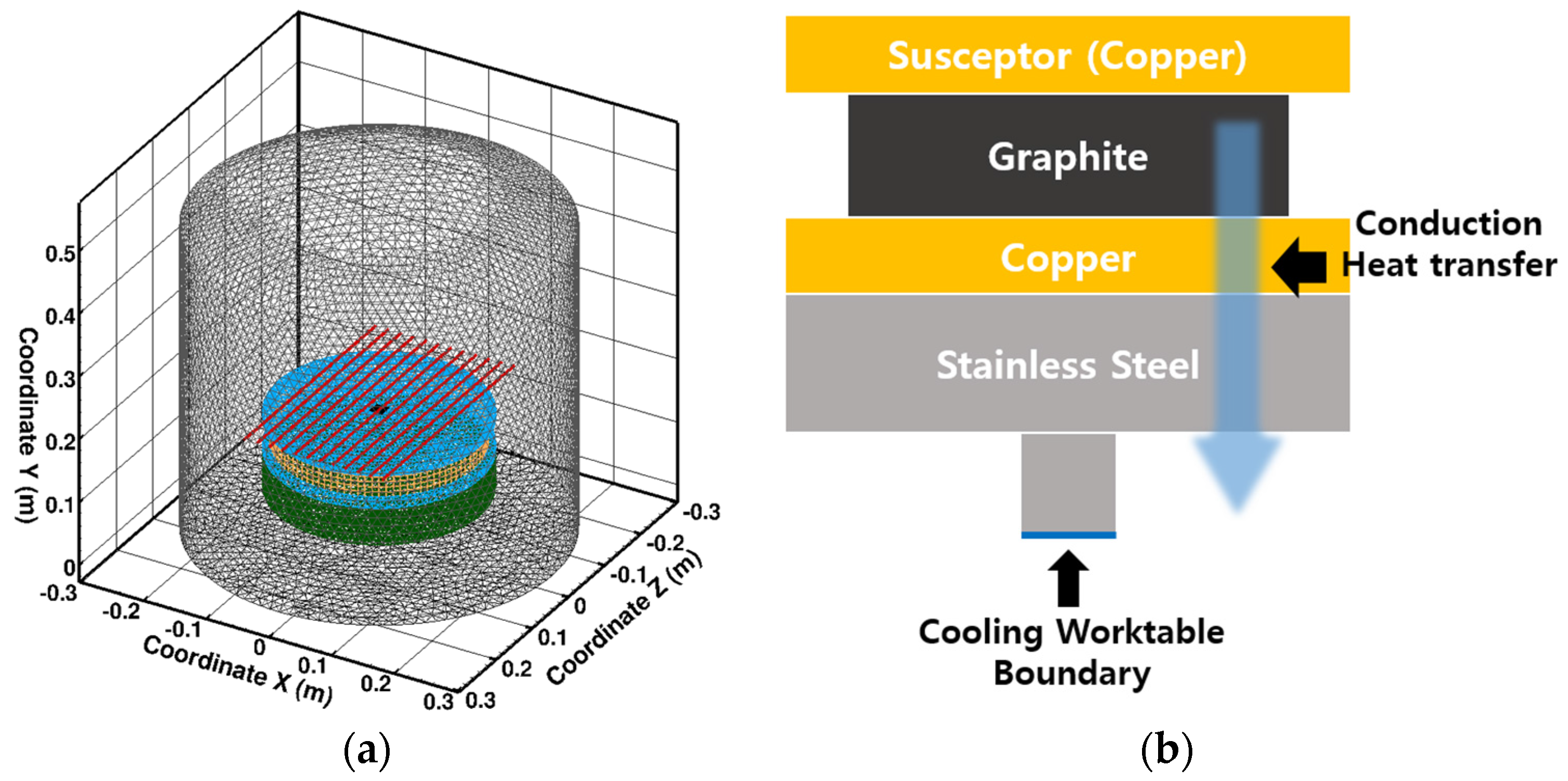
The HF-CVD system was described using the three-dimensional (3-D) geometry in
Figure 1a, which is divided into control volumes based on Cartesian coordinates (X, Y, Z). Most of the control volumes were described by triangle meshes, while some parts used hexagonal and pyramidal meshes to express the system in 3-D. The numbers of cells and nodes were 421,159, and 2,414,871, respectively. The conservation equations used for the simulated heat transfer in the HF-CVD system were as follows:
Energy conservation
where ρ is the density of fluid,
is the velocity vector,
is the pressure,
is the viscosity coefficient,
is the temperature,
is the thermal conductivity, and
is the heat source.
The conservation of the thermal radiation also has to be calculated to consider the radiative heat transfer. The discrete ordinate (DO) model was used in this simulation. The DO model is well suited for applications that involve participating media, and can be used for gray body and diverse optical thicknesses. This model is also used for predicting radiative heat transfer for most engineering applications.
In this model, the radiative transfer equation (RTE) is as follows:
where
are the position and direction vectors, respectively,
is the absorption coefficient,
is the scattering coefficient,
is the radiation intensity,
is the refractive index,
is the Stefan-Boltzmann constant,
is the phase function, and
is the solid angle.
A few details were assumed for the numerical simulation. First, an isothermal boundary condition at 350 K was used for the cooling chamber wall and the bottom of the worktable.
Figure 1b is a schematic diagram of a simplified concept of the cooling worktable assembly. In the present work, the heat sinking through the worktable assembly was regarded as conductive heat transfer through a temperature gradient of the four layers of the worktable and supports, composed of graphite, copper, and stainless-steel disks. Second, all of the materials were considered to be a gray body. It is impossible to describe the correct emissivity using exact values for the wavelength, the temperature, the roughness, and so on, because they are unpredictable functions. Therefore, a certain value of emissivity had to be assumed, and this value was determined to be a little higher value than that of the general metal, considering oxidation of the construction materials in the HF-CVD system.
In this work, the emissivity of the Ta filament was determined to be 0.5. In the experiment, the surface of a Ta wire was changed into TaC during the HF-CVD process. Since the emissivity of a typical TaC is known to be 0.40–0.46, the value of 0.5 was selected in the present work, considering a rough filament surface [
13]. Finally, the effect of absorbing and scattering through the participating media was neglected, because the HF-CVD system was operated at low pressure, and the participating media consisted of the gases.
The thermal condition of the Ta filament was used as the heat flux boundary. The total input power was considered to be distributed evenly to all 12 filaments. For example, each filament operated at 1 kW when the total input power was 12 kW. The operating pressure was fixed at 4000 Pa.
2.2. Experimental Work Using HF-CVD
A silicon wafer (100) with thickness of 0.5 mm was used as a substrate, because the thermal expansion coefficient of silicon at high temperatures is similar to that of diamond, and the residual thermal stress generated in the substrate during diamond coating can be minimized, so the adhesion between the diamond and silicon wafer can be improved. Before depositing the diamond film, the silicon wafer was pretreated. The pretreatment was performed by mixing diamond particles (500 nm–1 um) and glycerin at a ratio of 2:5 and then applying it to a silicon wafer and rubbing it. After washing with acetone to remove the glycerin, the wafer was placed in an acetone solution and ultrasonically cleaned for 10 min.
The purpose of this preprocessing work is to increase the roughness of the silicon wafer surface, and seed the diamond particles on the silicon wafer. As the surface roughness increases, the surface energy increases, which makes it easier to deposit the diamond. The growth rate of the diamond can be accelerated by the influence of the residual diamond particles [
14].
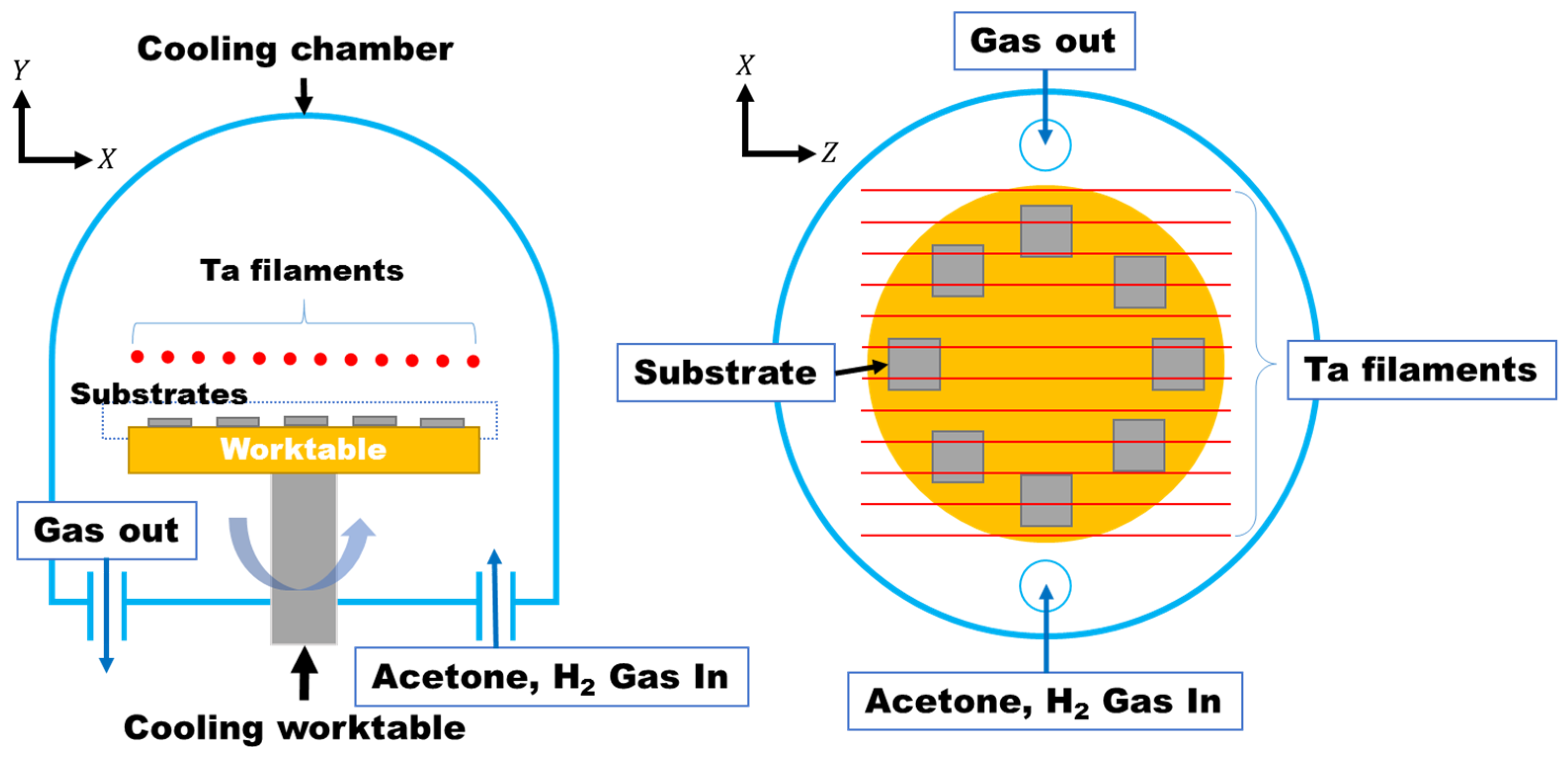
Deposition of the diamond was performed using HF-CVD. The carbon source was acetone and the reaction gas with acetone inside the chamber was hydrogen. The acetone was supplied into the chamber by bubbling with hydrogen as a carrier gas. The temperature of the acetone solution was controlled by using a constant temperature bath. Antifreeze liquid was placed in a constant temperature bath, and the bubbler containing the acetone solution was immersed in the antifreeze solution at 0 °C to maintain the temperature of the acetone solution at 0 °C. Hydrogen gas as the reaction gas and acetone as the carbon source were supplied into the chamber using a separate flow rate control device.
The pretreated silicon wafers were placed on a worktable (φ30 cm) in the chamber as shown in
Figure 2, and the worktable was rotated to ensure the uniform coating of the diamond.
Based on the previously calculated values, the appropriate power and pressure for the HF-CVD operation conditions were set and applied to the practical experiments.
The distance between the filament and the worktable was fixed at 10 mm and the pressure inside the chamber was set to 4000 Pa. The applied power of the filament was varied to observe the condition of the diamond coating depending on temperature. The detailed experimental data are presented in
Table 1. Where
Cn is the acetone that bubbled by hydrogen.
Analysis of the deposited diamond was performed using FE-SEM (S-4800, Hitachi, Ibaraki, Japan) and the size, morphology, and density of the deposited diamond were analyzed. Raman spectroscopy (Horiba, Jobin Yvon, Les Ulis, France) was used to evaluate the quality of the deposited diamond. The instrument was operated with an argon laser working at an excitation wavelength of 514.5 nm and 1800 line/nm grating.
3. Results and Discussion
The results of the numerical calculation analysis indicated that the suitable diamond deposition temperature ranges were 2500–2800 K and 1070–1200 K for the filament and susceptor, respectively [
7,
15,
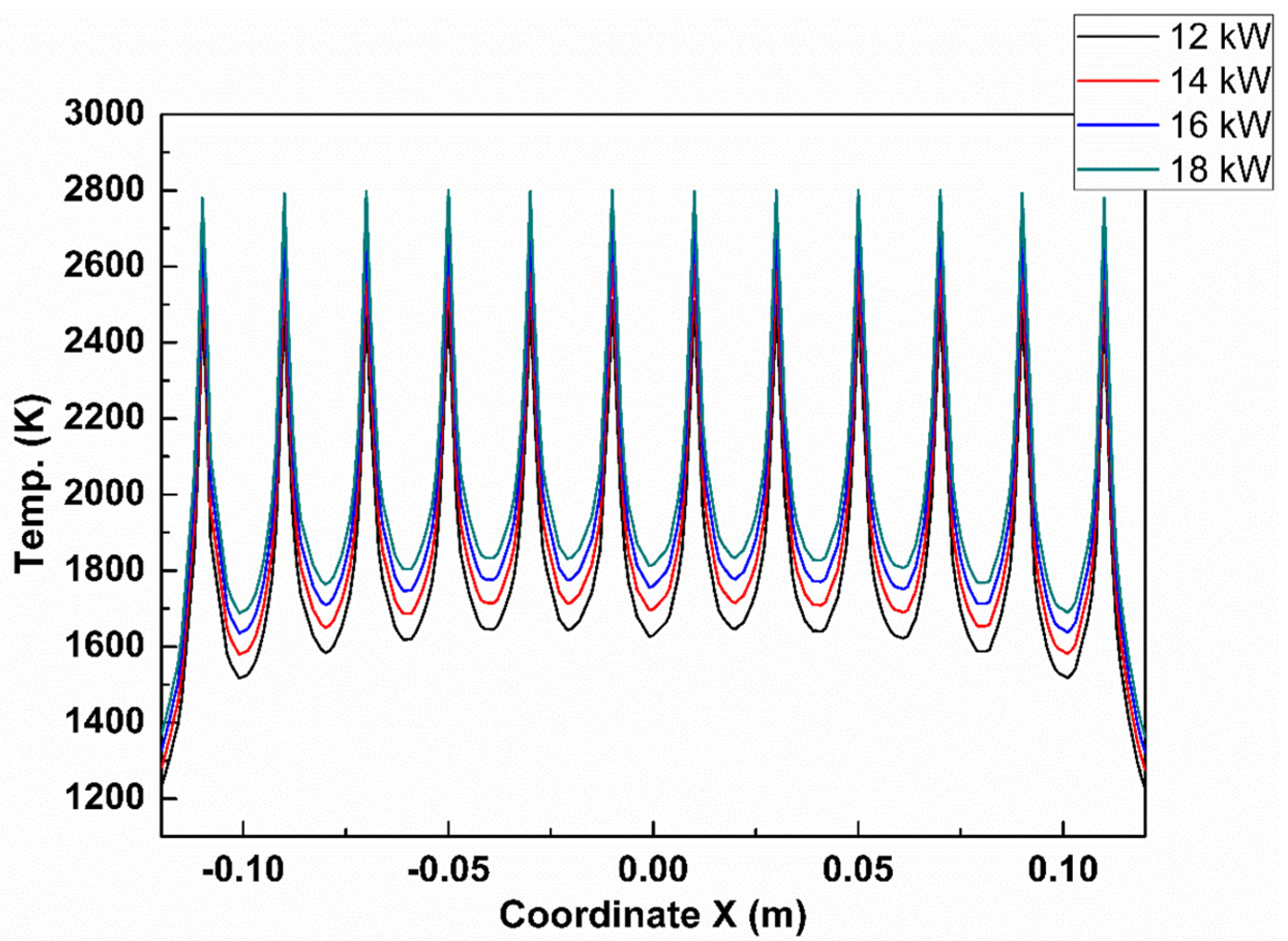
16]. Based on the results obtained from the numerical calculation, the experiment was conducted with the applied power range from 12 kW to 18 kW in our HF-CVD system.
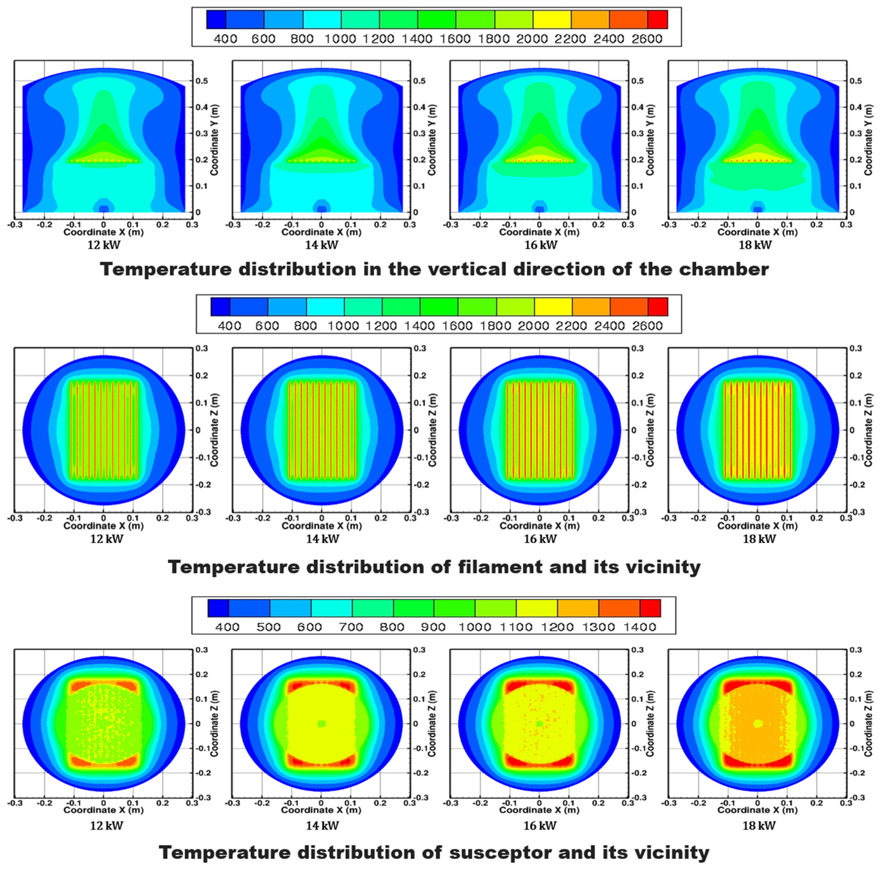
When the results of the numerical calculation were applied, a fluctuation in temperature was observed in the filament, as shown in
Figure 3 and
Figure 4. The temperature distribution of the susceptor in
Figure 4 was not uniform due to the influence of the temperature fluctuation in the filament. This can produce a non-uniform diamond deposition. To solve this problem, the worktable was rotated [
17] at a speed of 6 rpm during deposition, to improve the distribution of the temperature field.
The inside of the chamber could be seen through the quartz glass outside the chamber. A two-color pyrometer (E1RH-F1-L-0-0, Fluke, Merseburg, Germany) was used to measure the temperature through the quartz glass, to verify the values obtained from the numerical calculations. Simulated temperatures on the filament were ~1% different than the measured temperatures. In the experiment, powers of 12, 14, 16, and 18 kW was applied to the 12 filaments in the diamond deposition step. Calculated and measured temperatures of the filament and calculated susceptor temperatures are listed in
Table 2 and
Table 3.
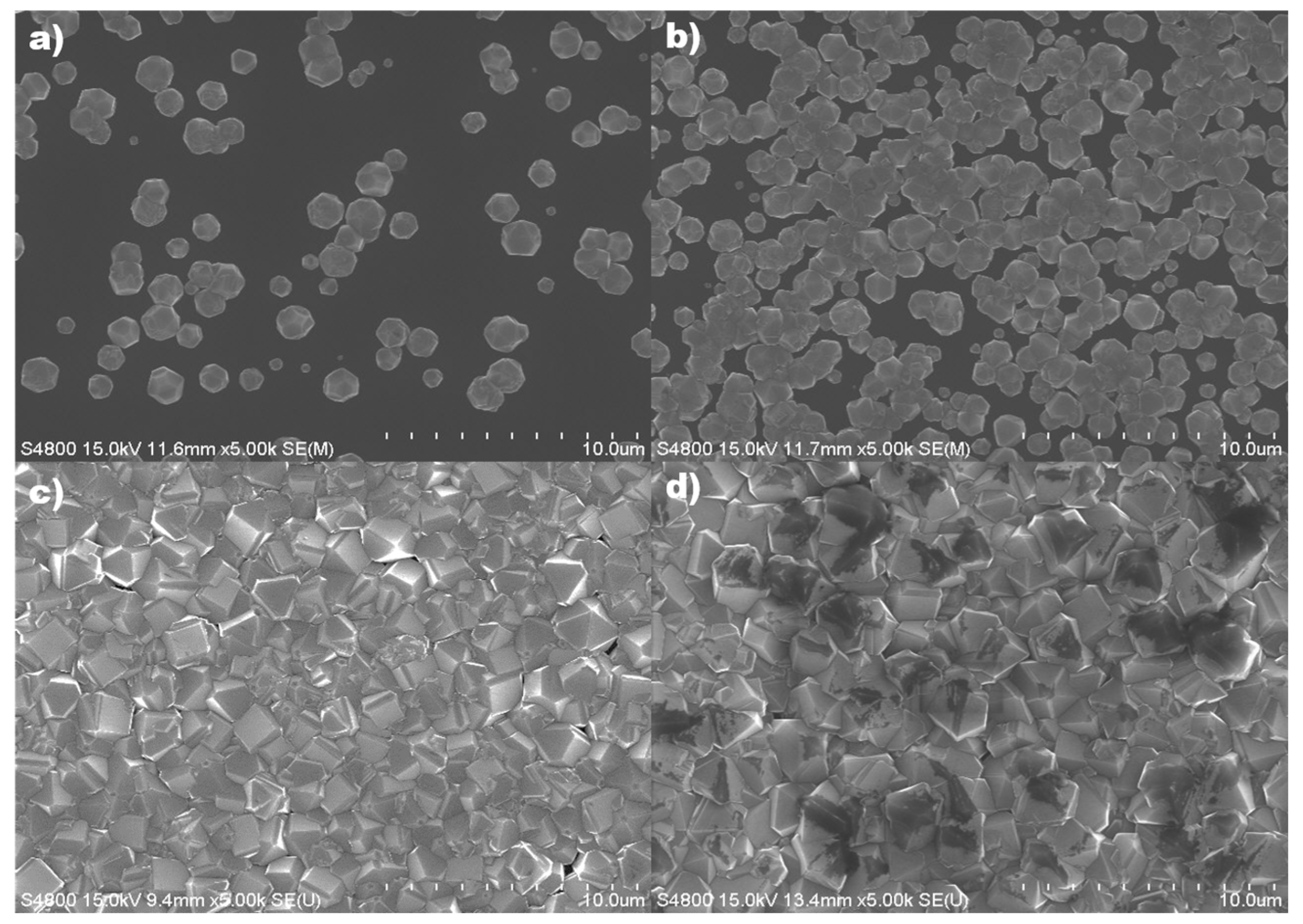
Based on the calculated temperature values, the results showed that the diamond film did not become a complete film at 12 kW and 14 kW. The growth was also very slow and the diamond film was not formed due to insufficient temperature during the diamond deposition. As shown in
Figure 5, the average grain size, which measured by the Image J program (1.51j8), was slightly larger at 18 kW (~1.99 μm) than at 16 kW (~1.53 μm), due to the higher temperature. However,
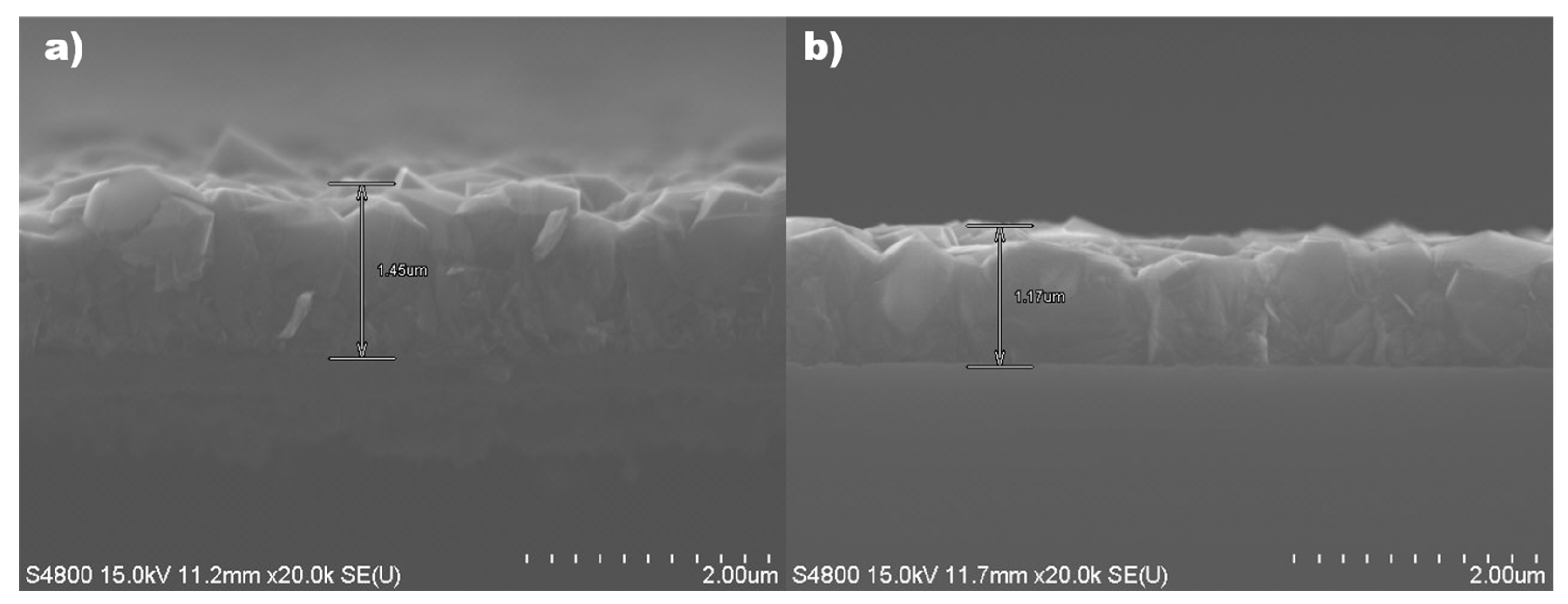
Figure 6 shows that the film thickness at 18 kW was less than that produced at 16 kW. This means that when the diamond is deposited at a high temperature, the surface of the deposited diamond is converted to amorphous carbon [
18,
19,
20,
21]. During diamond coating at high temperatures, the deposition of diamond and etching of amorphous carbon occur simultaneously. At this time, the etching rate of diamond converted to amorphous carbon is faster than the deposition rate of diamond [
22]. Therefore, the overall deposition rate at an applied power of 18 kW is reduced by the effect of diamond converted to amorphous carbon in comparison to that deposited at an applied power of 16 kW.
On the other hand, at 16 kW, the morphology of the diamond film was uniform, and unlike the case of the surface deposited at 18 kW, no amorphous carbonization progression was found. In fact, the diamond film was deposited on the entire substrate in the form of a complete film without any voids.
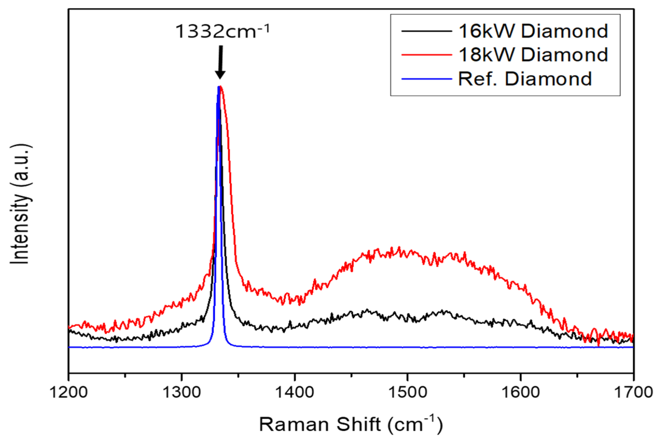
The Raman spectroscopy method is generally used to identify the peak 1332 cm
−1 for diamond characterization during diamond film deposition. In order to analyze the results, it is necessary to analyze not only the diamond characteristic peak but also the black parts (amorphous carbons) found in
Figure 5d. For this analysis, regions ranging from 1200 cm
−1 to 1700 cm
−1, including the diamond characteristic peak 1332 cm
−1 region, were analyzed. The analysis was made with reference to a diamond single crystal and only the 16 kW and 18 kW specimens with a complete diamond film morphology were analyzed, since no diamond film was formed at 12 kW and 14 kW.
The 1332 cm
−1 peak was observed for both the 16 kW and 18 kW samples, as shown in
Figure 7, compared to the reference diamond. However, at 18 kW, due to the high temperature of the filaments and substrate, the amorphous carbonization progression of the diamond caused broad D-mode and G-mode peaks between 1420 cm
−1 and 1580 cm
−1 [
18,
23]. This result shows that the deposition rate of 18 kW is lower than that of 16 kW in
Figure 6. This is because the etching rate of amorphous carbon is faster than the deposition rate of diamond due to the progress of amorphous carbonization.
4. Conclusions
The temperature of the filament and susceptor in the HF-CVD system is a very important factor affecting diamond deposition. Using a numerical analysis, the filament and susceptor temperatures were calculated depending on applied power, and these calculated values of applied power were used for diamond deposition in the actual experiments. In the experiments, the supply of a carbon source, pressure, and all other conditions were identical, and only the applied power was different. The filament temperature at different power levels was calculated to be 2512–2802 K, and the calculated temperatures were verified by comparing them to experimental measurements obtained using a two-color pyrometer. The difference between the calculated temperature and the actual measured value was found to be about 1%.
When powers of 12 kW and 14 kW were applied, the diamond film was not formed because the temperature was too low for diamond deposition. On the other hand, when the power of 18 kW was applied, amorphous carbon was observed, because that temperature was higher than the optimum temperature for diamond deposition, and caused a slow growth rate. The most successful deposition of diamond film and the highest growth rate were observed at an applied power of 16 kW, at which the temperatures of the filament and susceptor were 2715 K and 1161 K. At that power, the diamond film has much less non-diamond components than that grown at 18 kW, and the deposition rate was 0.18 μm/h, which was the highest of all applied powers.


 ,
, 


