Article

The Dispersion Tolerance of Micro/Nano Particle in Polydimethylsiloxane and Its Influence on the Properties of Fouling Release Coatings Based on Polydimethylsiloxane

Key Lab of Ship-Machinery Maintenance & Manufacture, Dalian Maritime University, Dalian 116026, China
*
Author to whom correspondence should be addressed.
Coatings 2017, 7(7), 107; https://doi.org/10.3390/coatings7070107
Submission received: 21 June 2017 / Revised: 14 July 2017 / Accepted: 19 July 2017 / Published: 21 July 2017
(This article belongs to the Special Issue Novel Marine Antifouling Coatings)

Abstract

:
Particles can be used to improve the mechanical properties of fouling release coatings based on polydimethylsiloxane (PDMS). In this study, coatings were prepared by high speed stirring using seven types of particles, with different particle size from nanometer to micrometer. The influence of specific surface area of the particles on the dispersion tolerance was investigated. The results showed that the dispersion tolerance of particles in PDMS decreased with the increase in specific surface area of the particle, and for nano particles, the factor most affecting the dispersion tolerance was the specific surface area of agglomerate particle. Subsequently, the surface properties, mechanical properties, and biofilm adhesion assay of coatings were investigated. Results indicated that surface roughness increased with the increase of dispersion tolerance. Surface roughness of samples improved the hydrophobicity of samples, yet the polar chemical group of nano silica and fumed silica reduced the hydrophobicity of samples. Further, particles could enhance the mechanical properties of coating, especially nano particles. Compared to the coating without particle, biofilm adhesion performance of coating with particles decreased, which was determined by the increase of the elastic modulus and surface roughness of coatings.

1. Introduction

Marine biofouling generally refers to the undesirable adhesion of marine organisms onto objects with the immersion in seawater. Marine biofouling causes the increase of energy consumption and emission of Greenhouse Gas [1,2,3], while it also damages and corrodes the structure of equipment immersed in water bodies, such as shipping vessels and offshore rigs [4,5]. These problems reduce production efficiency in related industries [6] and ultimately harm the development of the economy. Thus, many approaches have been exploited to mitigate fouling and one of the most effective ways is using antifouling coating [7]. However, the most efficient coatings, tributyl tin (TBT)-based coatings, inhibited marine fouling through the release of toxic substances. That causes imposex, intersex, and sterility for marine organisms, as well as altering shell growth in molluscs [8,9]. It has been limited by the International Marine Organization (IMO) in 2001. As an alternative environmentally-friendly antifouling coating, fouling release coatings based on polydimethylsiloxane (PDMS) have long-lasting antifouling efficiency and non-toxic releases [1,3,7]. It has become the focus of the development of new antifouling coatings.
This is a very complex and dynamic process for marine biofouling [10]. It includes four stages: (1) the formation of a conditioning layer; (2) the settlement of microorganisms; (3) the colonization of algal spores and marine larvae; and (4) the attachment of large organisms [11,12,13]. There are large number of proteins, polysaccharides, and other organic materials in the marine environment, and these organic materials form conditioning layers. Surfaces of objects immersed in seawater will be covered inevitably by the conditioning layer in a short time. Thus, reducing the settlement of microorganisms becomes the primary consideration, and inhibition of this stage can effectively reduce the damage of the follow-up stages. Specifically, it is experimentally confirmed that adhesion is proportional to the value, which is equal to the square root of the product of the elastic modulus (E) and surface free energy (γ) [14]. It can be defined as the relative adhesion factor, and it reveals that the low elastic modulus and low surface energy is better able to inhibit marine fouling, especially in microorganisms. In addition, the surface smoothness and thickness of coating also have an impact on the antifouling effect [14].
Fouling release coating based on PDMS has low surface energy and low elastic modulus [14]. These properties minimize the adhesion strength between marine organisms, especially in microorganisms and substrate surfaces, and marine biofouling is easily removed via mechanical cleaning or hydrodynamic during sailing [1,15]. More importantly, coating does not release toxic substances. However, this antifouling coating has the following disadvantages [1,4]: mechanical damage is susceptible to happen and also displays poor adhesion strength with substrates [16]. The reason for these disadvantages is in the molecular structure of the polymer. Silicon atom and oxygen atom alternates to form the basic backbone of PDMS: –Si–O–. Distinguishing from the common basic backbone of –C–C–, the molecular chain of PDMS is very flexible, and causes poor mechanical strength of PDMS polymer. In addition, PDMS polymer exhibits non-polarity, and weakens the adhesion with substrates.
In recent years, researchers have made a lot of work to solve the shortcomings of this coating. Most research studies have focused on PDMS-modified material, whereby PDMS is used as a substrate, and other organic materials provide high mechanical properties [17,18,19,20,21,22,23,24,25,26]. However, it is less on determining the mechanical properties of coating influenced by particle.
As an important part of antifouling coating, in addition to the basic function–coloration and cover, particles also play an important role in enhancing the mechanical properties of coatings [27,28]. It is expected that the mechanical properties of coatings based on PDMS will be changed owing to the addition of the particle, thereby likely changing the antifouling performance. However, the influence of particles on coatings based on PDMS has been researched independently [29,30,31,32,33]. Further, most studies were limited to changing the additive amount of particles. There is no systematic comparative study for different particles. Particles could not be mixed unlimitedly into PDMS. When it reaches the maximum mixing value, more than this value, particles will precipitate. Further, the value is also an important parameter for comparing and analyzing the effects of different kinds of particles on coatings. Research of maximum mixing value of the particle can also help to determine the effect of the particle on coating properties. Thus, the PDMS coatings reinforced by particles were prepared by a two-stage process in the current study: (1) particles and PDMS were firstly mixed via high speed mechanical agitation to prepare the pre-dispersed slurry; (2) then coating was reacted by pre-dispersed slurry and curing agent under catalytic conditions. A total of seven types of particles were used in this experiment, including barium sulfate, tourmaline, titanium dioxide, nano-silica, fumed silica, nano calcium carbonate, and nano titanium dioxide. The particle size of these particles is from micrometer to nanometer. Further, these particles have been applied in coating industry. For barium sulfate, it was used to improve mechanical properties of coatings [34]. Tourmaline has the characteristics of releasing negative ions and radiating far infrared rays [29], and can be applied in the antifouling field and affect the adhesion of fouling organism. Titanium dioxide also has good cover function. For nano particles, the influence of nano effect on marine coatings has also become the focus of research [30,31,32]. Research was performed to analyze the influence factors of the dispersion tolerance. Further, the effects of particle on properties of coatings were also investigated under the condition of dispersion tolerance.

2. Materials and Methods

2.1. Materials

Hydroxyl-terminated polydimethylsiloxane (PDMS) monomer was obtained from Dayi Chemical Industry Co., Ltd. (Yantai, China), and the viscosity of PDMS was 10,000 mPa·s. Ethylorthosilicate (TEOS) and bismuth neodecanoate (BiND) were analytical grade and purchased from Tianjin Kemiou Chemical Reagent Co., Ltd. (Tianjin, China). Xylene and ethyl acetate were also analytical grade and supplied from Yongda Chemical Reagent Co., Ltd. (Tianjin, China). Seven particles, such as, barium sulfate, tourmaline, titanium dioxide, nano-silica, fumed silica, nano calcium carbonate, and nano titanium dioxide were purchased.

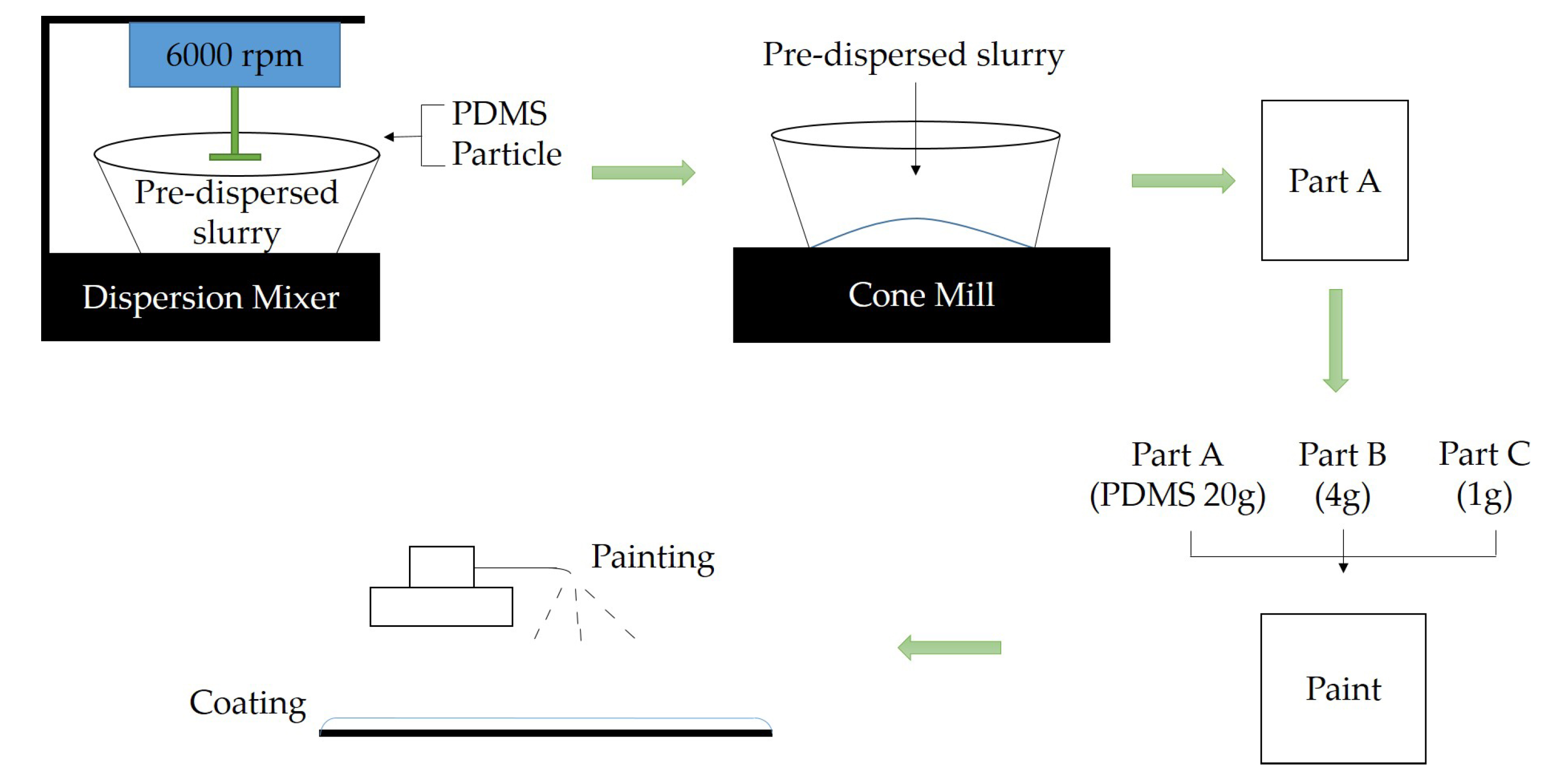
2.2. Preparation of Coating Samples

The coating was composed of three parts. Pre-dispersed slurry included PDMS and particles. TEOS mixed with xylene to make the curing agent (part B), and the mixture of BiND and ethyl acetate was prepared into catalytic agent (part C). The two-stage method of preparation process was as follows: PDMS (50 g) and particles after drying were added into a 500 mL stirring tank at 6000 rpm, and the mass value of particle was controlled at 0.1 g during each addition by using TD5102 electronic balance (this was purchased from Tianma Instrument Factory, Tianjin, China, and the measuring accuracy of this electronic balance is 0.1 g). The mixture needed to be stirred for 3 min after each addition of particle, and the dispersion was observed by SMS-313 stereomicroscope (Wassin Co., Ltd., Bisamberg, Austria) to ensure the accuracy of dispersion tolerance (the specific observation method was as follows: the pre-dispersed slurry was observed by a stereomicroscope, and if no insoluble particle existed in the field of view, particles could continue to be added), then pre-dispersed slurry was ground using cone mill, and afterwards, pre-dispersed slurry (part B and part C) were added to a clean container and mixed well. The whole process was also shown in Figure 1. The coating was painted on glass slides with dimensions of 75 mm × 25 mm × 1 mm, and, in the meanwhile, poured into a Teflon mold with dimensions of 150 mm × 150 mm × 3 mm. The slide samples were used for surface properties and biofilm adhesion tests and the casting samples were used for mechanical properties tests.

2.3. Characterization

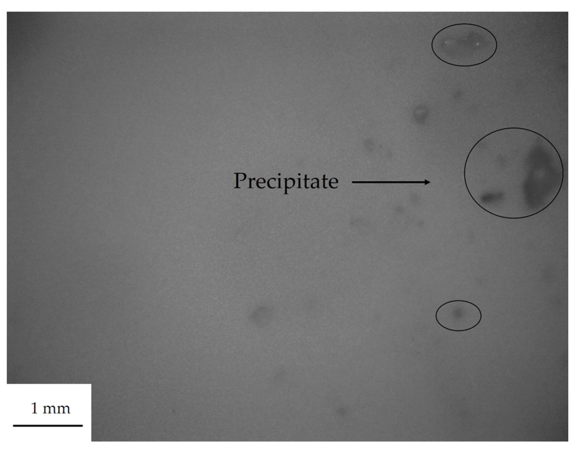
2.3.1. Scanning Electron Microscope (SEM)

The morphology of particle was observed by SUPRA 55 SEM. The test mode of particle was SE2, and the value of particle size was calculated by the Adobe Photoshop software (CS6).

2.3.2. Confocal Laser Scanning Microscope (CLSM)

The morphology of coating was analyzed by Olympus OLS4000 CLSM (OLYMPUS (China) Co., Ltd., Beijing, China) in the field of view 64 μm × 64 μm. The surface roughness of coating was measured by the software of LEXT, and the Software Version is 2.2.4.

2.3.3. Water Contact Angle and Surface Free Energy

Water contact angle measurements were conducted using the sessile drop method on a JC2000C contact angle measurement system. A 3-μL droplet of distilled H2O was placed on the sample surface using a syringe. Digital images of the droplet silhouette were captured with a charge-couple device camera and the contact angles were evaluated using the measuring angle method. For each sample, the mean of the contact angle measurements for the three points was calculated. The surface free energies were calculated by using Owens two-liquid method [35], and the second liquid is the non-polar diiodomethane. It was calculated as follows: Equations (1), (2), and (3), where σ S d denotes the dispersive force and σ s p refers to the polar force of the sample surface.
σ s p = [ ( 137.5 + 256.1 × cos θ H 2 O 118.6 × cos θ CH 2 I 2 ) / 44.92 ] 2
σ S d = [ ( 139.9 + 181.4 × cos θ CH 2 I 2 41.5 × cos θ H 2 O ) / 44.92 ] 2
σ S = σ s p + σ S d

2.3.4. Mechanical Properties of Coating

Tensile samples were prepared into strips (150 mm × 20 mm × 2 mm) and then stretched on a Labthink XLM auto tensile tester (Labthink Co., Ltd., Jinan, China). Breaking strength and breaking elongation rate were recorded. Elastic modulus was fitted with the data, which showed that the strain was less than 0.02 mm/mm.
HT220 shore hardness tester was applied to test the hardness of coating. This test also required membrane thickness exceeding 5 mm, thus, the prepared membrane needed to be folded repeatedly to meet the experimental requirement.

2.3.5. Biofilm Adhesion Assay

Seawater bacteria adhesion studies were conducted to evaluate the anti-adhesion property of the samples. Crystal violet was used to evaluate the content of seawater bacteria adhering to the surface of coating. Six coated glass slides were immersed in 400 mL fresh seawater at 28 °C. After 24 h, three slides were rinsed softly in sterile deionized water to remove unsettled bacteria, whereas, the other three slides were washed with a high-pressure water gun. All slides were dried in the sterile working platform to remove the residual water. Each slide was placed in 50 mL sterile centrifuge tubes with 45 mL 2216E liquid culture medium at 28 °C for 24 h. After that, slides were also rinsed softly in sterile deionized water and dried in a sterile environment. Then, glass slides were poured into crystal violet (ethanol) solution (0.03 wt %) for 15 min. Slides with crystal violet stain were immersed in acetic acid solution (36 wt %). Then, the resulting solution was poured into a quartz cuvette with a path length of 1 cm, and the absorbance of the solution was determined at fixed wavelengths (590 nm) to calculate the concentration of crystal violet using ultraviolet-visible spectroscopy (Labtech UV-2000, Labtech Co., Ltd., Beijing, China). By measuring the absorbance of liquid, the anti-adhesion properties of coating based on PDMS could be characterized. The remove rate that marine bacteria adhered to the coating samples was calculated by the formula: Equation (4). Where Da, Db, R represents, the absorbance of washing samples, the absorbance of rinsing samples, and the remove rate of biofilm adhesion.
R = ( D b D a ) / D b × 100 %

3. Results and Discussion

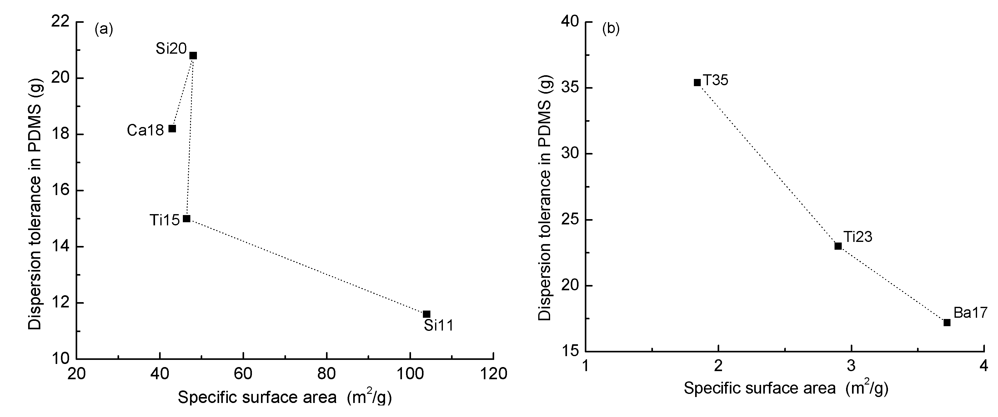
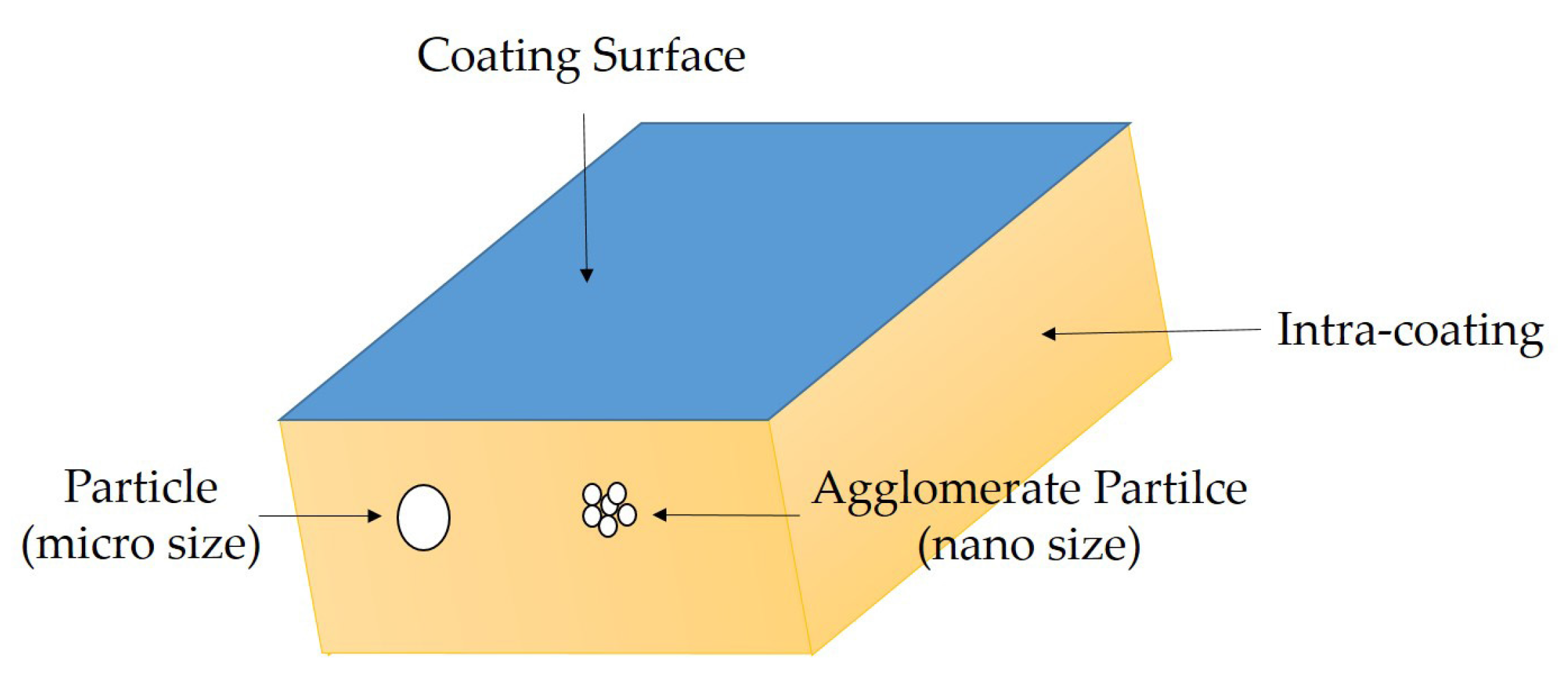
3.1. The Dispersion Tolerance of Particle in Polydimethylsiloxane (PDMS)

The dispersion tolerance (Table 1) was defined by the upper limit of the stable dispersion of the particle in 100 g of PDMS. If the additive amount of particle is more than this value, it is separated from the PDMS and forms large precipitate in the process of storage. By using a stereomicroscope, the precipitate was observed (Figure 2). That could ensure the accuracy of the dispersion tolerance test. It was showed in Figure 2 that precipitate appeared in the field of view when the additive amount of particle was beyond the dispersion tolerance.
Morphologies of particle were shown in Figure 3 and the measured particle size was listed in Table 2. For small size particles, the particle size is related to the specific surface area of particles. In this study, the specific surface area of particles was measured by BET multipoint method via an automatic nitrogen adsorption specific surface instrument (Beishide Instrument Technology Co., Ltd., Beijing, China).
Research results showed that the value of dispersion tolerance of micro particle increased with decreasing specific surface area (Figure 4b). Although the chemical properties, type, and shapes of particles are different, the particles were dispersed in PDMS in a physical way. Thus, an important factor to determine the dispersion tolerance is the contact area between particles and PDMS. PDMS wraps particles up, meaning the area of encapsulated particles is equal to the gap area of the polymer material. Limited gap area limits the number of particles. That will theoretically cause more dispersion tolerance of the particle with less specific surface area. Further, for nano particle, the dispersion tolerance in PDMS is very small due to its larger specific surface area. However, the actual results for nano particle are contrary to the theory (Figure 4a). Meanwhile, comparison of Figure 4a,b, the specific surface area of nano particle is much larger than that of micro particle—nevertheless, the dispersion tolerance is of the same order of magnitude.
After high-speed stirring, micro particles could be separated from each other, so as to make full contact with the molecular chain gap. However, the nanometer size effect of nano particles resulted in the aggregation of particles, and high-speed stirring did not break the aggregation. Therefore, the nano particle was still dispersed in PDMS resin in a state of agglomeration. The three types of micro particle without agglomeration were fully wrapped by PDMS. The gap area of PDMS was obtained by calculation. Then, the specific surface area of agglomerate nano particle was also calculated (Table 2). It could be found by contrast that the specific surface area of agglomerate particle was much smaller than that of the true particle. This was also shown in Figure 5.
The admeasurement of surface roughness could provide essential information on surface morphology of coatings. Morphologies of coating via CLSM were shown in Figure 6. Compared with comparison sample (P0), the surface roughness of other samples increased due to the addition of the particle. It was analyzed from morphologies of coating that there was no regularity in the surface out-of-flatness of coating, and it could affect biofouling.
The surface roughness of samples was measured. The addition of particles broke the original smoothness of the coating based on PDMS and caused the appearance of rough surfaces. For micro particles, the surface roughness increased with the decreasing of specific surface area of the particle (Figure 7b). For nano particles, the specific surface area of particle refers to that of agglomerate particles, and the surface roughness and agglomerate specific surface area are also satisfied with this relationship (Figure 7a). Further experimental results shows that the increase of dispersion tolerance increases the surface roughness (Table 3). The existence of particles (include dispersed particle and agglomerate particle) in the gap of the molecular chain of PDMS has the same limited area which is determined by the area of the gap. Therefore, the larger the specific surface area was, the smaller the dispersion tolerance revealed, and the smaller surface roughness of coating.

3.2. Surface Properties

Water contact angle and surface free energies can provide important information on the wetting behavior and antifouling property of coatings. The contact angle results and surface free energies were presented in Table 3. Compared with the coating P0, water contact angle of the coating (Si20, Si11) decreased, while the contact angle of other coatings increased. Related research has indicated that increasing roughness of a hydrophobic solid enhanced its hydrophobicity [36,37,38]. This hydrophobicity phenomenon can be explained by Wenzel model [36]. Apart from samples Si20 and Si11, other sample data could be consistent with this model. Whereas the Wenzel model is mainly explained by physics, it did not relate to the impact of chemical bonds. There were hydroxyl groups in nano silica and fumed silica, which was determined by the preparation process of particles. It also belonged to the chemical characteristics of particles. Therefore, the hydroxyl group was added into the coating, and it weakened the hydrophobicity of the coating. For samples Si20 and Si11, the effect of increased surface roughness of coatings on hydrophobicity was masked by the polarity of the particle. That caused decreases in the water contact angle of coatings (Si20, Si11).

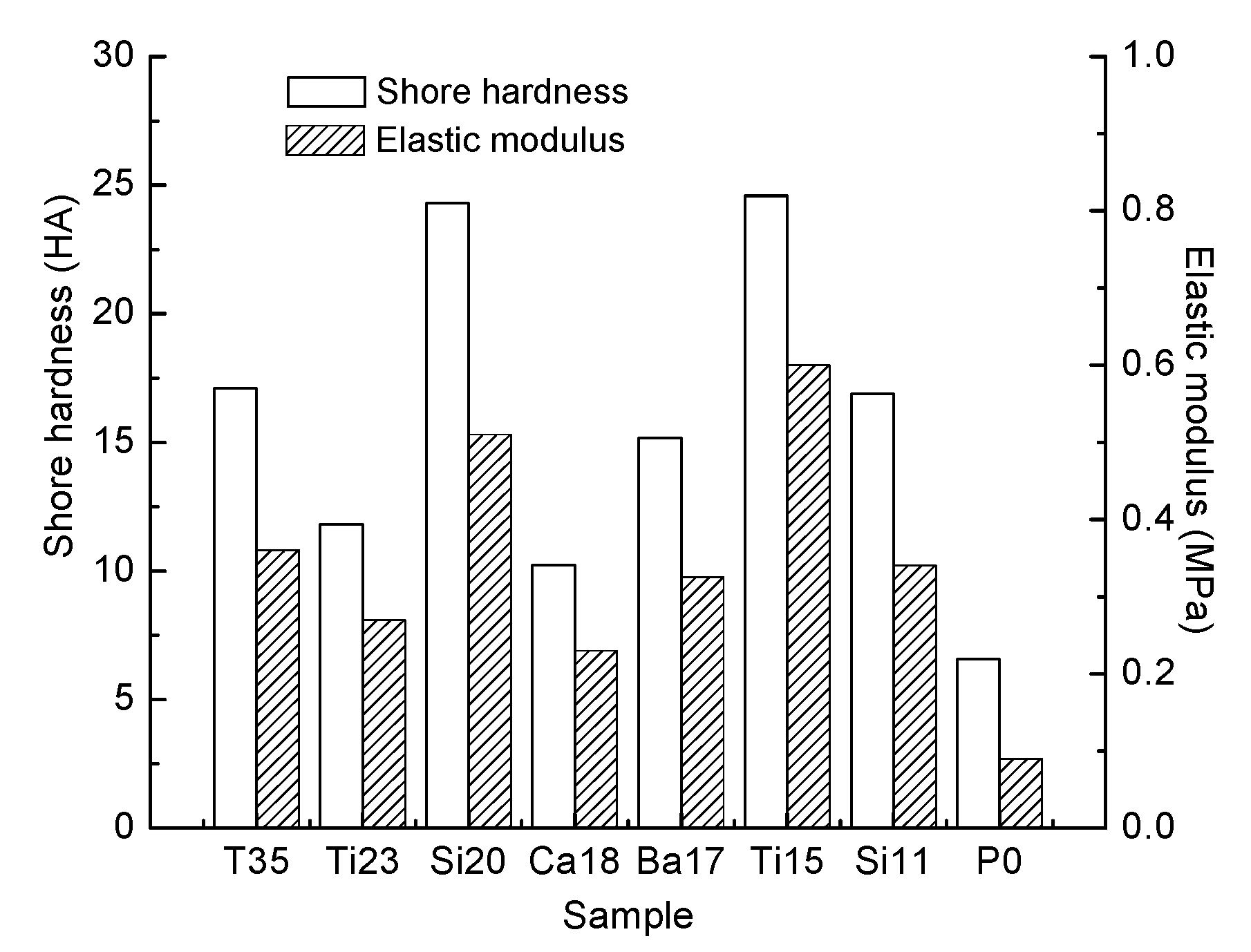
3.3. Mechanical Properties

In Figure 8 and Table 4, the tensile properties of the coating samples is shown. Experimental results showed the elastic modulus, shore hardness, breaking strength, and breaking elongation increased accordingly with the addition of the particle. PDMS mixed with particles to form the crosslink-structure. When the coating was suffering from stress, particle distributed in the crosslink-structure could disperse stress so that it caused the increase in mechanical properties. The difference in the mechanical properties of coatings was caused by different reinforcement effect of particle. The effect of nano particles enhancing the mechanical properties of coating was more obvious. Although nano particles existed in the PDMS with the state of aggregation, there was still no aggregation of particle dispersed into coating, and the small size effect of nano particle could better enhance the mechanical properties of coating. In this research, it was highest for coating with nano titanium dioxide on shore hardness and elastic modulus, and it was highest for coating with fumed silica on breaking strength and breaking elongation. The increase of the elastic modulus could cause the decrease of antifouling property, and this conclusion needed to be detected by biofilm adhesion experiment.

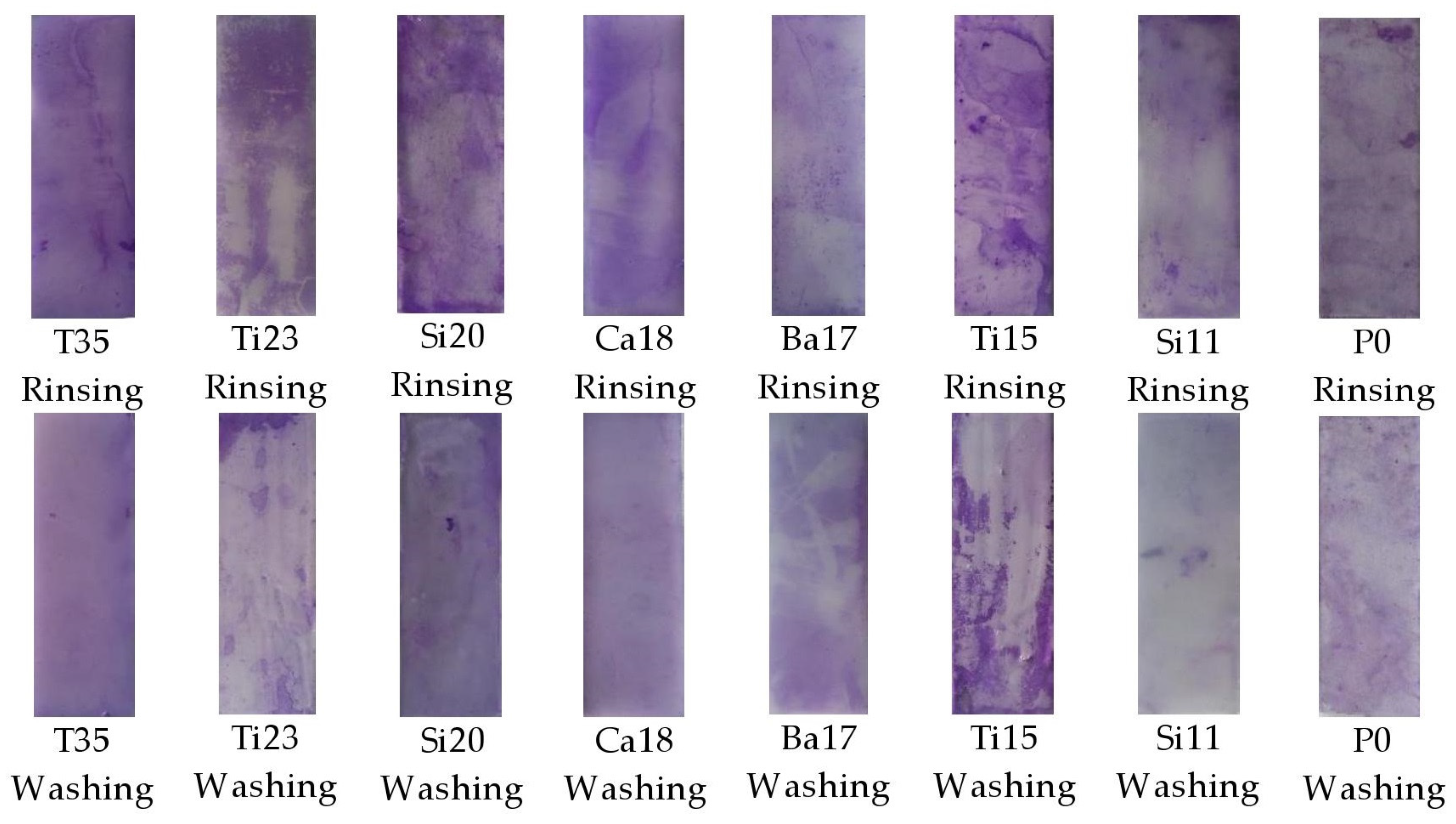
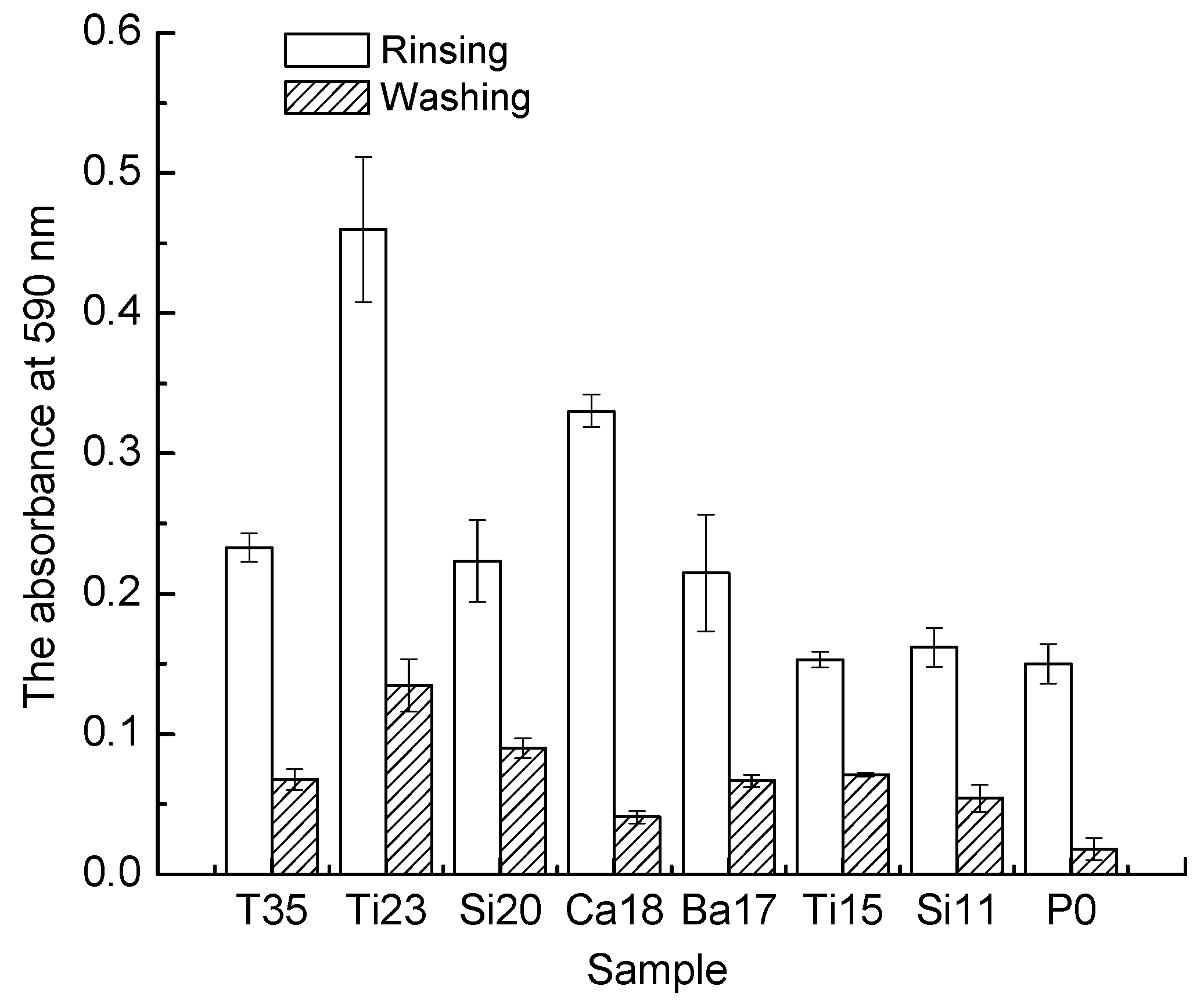
3.4. Biofilm Adhesion Assay

Crystal violet staining was used to label the bacteria attached to the sample. Figure 9 showed the adhesion of bacteria on the different samples. The difference between rinsing and washing could be clearly shown. Subsequently, the biofilm adhesion assay of coatings needed to be tested qualitatively, and the test data revealed by UV-Vis spectrophotometer. In all the experimental samples, the value of bacterial adhesion of P0 was the minimum (Figure 10). For fouling release based on PDMS, lower surface free energies of coatings could reduce biofouling. However, the results showed that the anti-biofilm adhesion properties of coatings added particles declined. For coatings added particles, the reason for the decrease of surface free energy (the increase of hydrophobicity) was the increase of surface roughness. The rough surface provided the fulcrum for the adhesion of fouling organisms, which made fouling organisms easier to assemble on the surface of coatings [2]. Further, the addition of particle improved the mechanical properties of coatings at the same time reduced the anti-adhesion properties of coatings. This result was in accordance with the theory of the relative adhesion factor. It was also revealed in Figure 11 that the tendency of the removed rate of biofilm adhesion was contrary to the value of the elastic modulus of coatings [39]. In high elastic modulus state, cleaning the bacteria required higher energy, so that the bacteria were more difficult to remove [40,41]. For this experiment, anti-biofilm adhesion of Ca18 was the best compared with other coating added particle after washing. It was suggested that the anti-biofilm adhesion of coatings was determined by the surface free energies, elastic modulus, and surface smoothness of coatings.

4. Conclusions

Dispersion tolerance of micro/nano particle in PDMS was examined, and their influence on the properties of fouling release coatings based on PDMS was measured. The results showed that the dispersion tolerance of the particle increased with decreasing specific surface area of the particle (for nano particle, the specific surface area of particle referred to that of the aggregates particle). The larger dispersion tolerance of particle was in PDMS, the greater surface roughness of coatings revealed. The increase of surface roughness of coatings also led to the enhancement of hydrophobicity of coatings. However, water contact angle of coatings for Si11 and Si20 decreased due to the polarity of the particle. Additionally, particle obviously enhanced the mechanical properties of coatings, in which the effect of nano particle was better. And biofilm adhesion assay showed that anti-biofilm adhesion property of coatings decreased with the increasing elastic modulus and surface roughness of coatings. Among all prepared coatings, Ca18 showed the best inhibition ability of biofilm adhesion under the dispersion tolerance condition.

Acknowledgments

This work was supported by National Nature Science Foundation of China (51079011, 51179018), the application basic research fund of the Ministry of Transport (2013329225330). The authors gratefully acknowledge for financial support.

Author Contributions

Miao Ba and Zhanping Zhang designed and performed the experiments; Miao Ba and Zhanping Zhang analyzed the data; Zhanping Zhang and Yuhong Qi contributed reagents/materials/analysis tools; Miao Ba wrote the paper.

Conflicts of Interest

The authors declare no conflict of interest.

References

  1. Lejars, M.; Margaillan, A.; Bressy, C. Fouling release coatings: A nontoxic alternative to biocidal antifouling coatings. Chem. Rev. 2012, 112, 4347–4390. [Google Scholar] [CrossRef] [PubMed]
  2. Yang, W.J.; Neoh, K.G.; Kang, E.T.; Teo, S.L.M.; Rittschof, D. Polymer brush coatings for combating marine. biofouling. Prog. Polym. Sci. 2014, 39, 1017–1042. [Google Scholar] [CrossRef]
  3. Callow, J.A.; Callow, M.E. Trends in the development of environmentally friendly fouling-resistant marine coatings. Nat. Commun. 2011, 2, 1–10. [Google Scholar] [CrossRef] [PubMed]
  4. Champ, M.A. A review of organotin regulatory strategies pending actions, related costs and benefits. Sci. Total Environ. 2000, 258, 21–71. [Google Scholar] [CrossRef]
  5. Yebra, D.M.; Kiil, S.; Dam-Johansen, K. Antifouling technology—Past, present and future steps towards efficient and environmentally friendly antifouling coatings. Prog. Org. Coat. 2004, 50, 75–104. [Google Scholar] [CrossRef]
  6. Nurioglu, A.G.; Esteves, A.C.C.; de With, G. Non-toxic, Nonbiocide-Release Antifouling Coatings Based on Molecular Structure Design for Marine Application. J. Mater. Chem. B. 2015, 3, 6547–6570. [Google Scholar] [CrossRef]
  7. Sandra, M.; Christine, B.; Francois-Xavier, P.; Claire, M.; Andre, M. Development of polyorganosilazane-silicone marine coatings. Prog. Org. Coat. 2014, 77, 1919–1928. [Google Scholar] [CrossRef]
  8. Evans, S.M.; Leksono, T. The use of whelks and oysters as biological indicators of pollution from antifouling paints. J. Biol. Educ. 1995, 29, 97–102. [Google Scholar] [CrossRef]
  9. Evans, S.M.; Leksono, T.; Mckinnell, P.D. Tributyltin pollution—A diminishing problem following legislation limiting the use of tbt-based antifouling paints. Mar. Pollut. Bull. 1995, 30, 14–21. [Google Scholar] [CrossRef]
  10. Magin, C.M.; Cooper, S.P.; Brennan, A.B. Non-toxic antifouling strategies. Mater. Today 2010, 13, 36–44. [Google Scholar] [CrossRef]
  11. Chambers, L.D.; Stokes, K.R.; Walsh, F.C.; Wood, R.J.K. Modern approaches to marine antifouling coatings. Surf. Coat. Technol. 2006, 201, 3642–3652. [Google Scholar] [CrossRef]
  12. Cao, S.; Wang, J.D.; Chen, H.S.; Chen, D.R. Progress of marine biofouling and antifouling technologies. Chin. Sci. Bull. 2011, 56, 598–612. [Google Scholar] [CrossRef]
  13. Zhang, Y.; Qi, Y.; Zhan, Z. Synthesis of PPG-TDI-BDO polyurethane and the influence of hard segment content on its structure and antifouling properties. Prog. Org. Coat. 2016, 97, 115–121. [Google Scholar] [CrossRef]
  14. Stein, J.; Truby, K.; Wood, C.D.; Stein, J.; Gardner, M.; Swain, G.; Kavanagh, C.; Kovach, B.; Schultz, M.; Wiebe, D.; et al. Silicone foul release coatings: Effect of the interaction of oil and coating functionalities on the magnitude of macrofouling attachment strengths. Biofouling 2003, 19, 71–82. [Google Scholar] [CrossRef] [PubMed]
  15. Dundu, A.; Franzka, S.; Ulbricht, M. Improved antifouling properties of polydimethylsiloxane films via formation of polysiloxane/polyzwitterion interpenertrating networe. Macromol. Rapid Commun. 2016, 37, 2030–2036. [Google Scholar] [CrossRef] [PubMed]
  16. Beigbeder, A.; Degee, P.; Conlan, S.L.; Mutton, R.J.; Clare, A.S.; Pettitt, M.E.; Callow, M.E.; Callow, J.A.; Dubosi, P. Preparation and characterisation of silicone-based coatings filled with carbon nanotubes and natural sepiolite and their application as marine fouling-release coatings. Biofouling 2008, 24, 291–302. [Google Scholar] [CrossRef] [PubMed]
  17. Marabotti, I.; Morelli, A.; Orsini, L.M.; Martinelli, E.; Galli, G.; Chiellini, E.; Lien, E.M.; Pettitt, M.E.; Callwo, M.E.; Callow, J.A.; et al. Fluorinated/siloxane copolymer blends for fouling release: Chemical characterization and biological evaluation with algae and barnacles. Biofouling 2009, 25, 481–493. [Google Scholar] [CrossRef] [PubMed]
  18. Martinelli, E.; Sarvothaman, M.K.; Galli, G.; Pettitt, M.E.; Callow, M.E.; Callow, J.A.; Conlan, S.L.; Clare, A.S.; Sugiharto, A.B.; Davies, C. Poly(dimethyl siloxane)(PDMS) network blends of amphiphilic acrylic copolymers with poly(ethylene glycol)-fluoroalkyl side chains for fouling-release coatings. II. Laboratory assays and field immersion trials. Biofouling 2012, 28, 571–582. [Google Scholar] [CrossRef] [PubMed]
  19. Martinelli, E.; Sarvothaman, M.K.; Alderighi, M.; Galli, G.; Mielczarski, E.; Mielczarski, J.A. PDMS network blends of amphiphilic acrylic copolymers with poly(ethylene-glycol)-fluoroalkyl side chains for fouling-release coatings. I. Chemistry and stability of the film surface. J. Polym. Sci. Part A 2012, 50, 2677–2686. [Google Scholar] [CrossRef]
  20. Arora, P.K. Fluorinated Organic Silicon Coating Material. U.S. Patent 7,674,927, 3 September 2010. [Google Scholar]
  21. Martinelli, E.; Suffredini, M.; Galli, G.; Glisenti, A.; Pettitt, M.E.; Callow, M.E.; Callow, J.A.; Williams, D.; Lyall, G. Amphiphilic block copolymer/poly(dimethylsiloxane) (PDMS) blends and nanocomposites for improved fouling-release. Biofouling 2011, 27, 529–541. [Google Scholar] [CrossRef] [PubMed]
  22. Kawakami, Y. Synthesis of silicone graft polymers and a study of their surface active properties. Macromol. Chem. Phys. 1984, 185, 9–18. [Google Scholar] [CrossRef]
  23. Ekin, A.; Webster, D. Combinatorial and high-throughput screening of the effect of siloxane composition on the surface properties of crosslinked siloxane–polyurethane coatings. J. Comb. Chem. 2007, 9, 178–188. [Google Scholar] [CrossRef] [PubMed]
  24. Fang, J.; Kelarakis, A.; Wang, D.Y.; Giannelis, E.P.; Finlay, J.A.; Callow, M.E.; Callow, J.A. Fouling release nanostructured coatings based on PDMS-polyurea segmented copolymers. Polymer 2010, 51, 2636–2642. [Google Scholar] [CrossRef]
  25. Ekin, A.; Webster, D.C.; Daniels, J.W.; Stafslien, S.J.; Casse, F.; Callow, J.A.; Callow, M.E. Synthesis, formulation, and characterization of siloxane–polyurethane coatings for underwater marine applications using combinatorial high-throughput experimentation. J. Coat. Technol. Res. 2007, 4, 435–451. [Google Scholar] [CrossRef]
  26. Sommer, S.; Ekin, A.; Webster, D.C.; Stafslien, S.J.; Daniels, J.; VanderWal, L.J.; Thompson, S.E.M.; Callow, M.E.; Callow, J.A. A preliminary study on the properties and fouling-release performance of siloxane–polyurethane coatings prepared from poly(dimethylsiloxane) (PDMS) macromers. Biofouling 2010, 26, 961–972. [Google Scholar] [CrossRef] [PubMed]
  27. Yilgor, I.; Bilgin, S.; Isik, M.; Yilgor, E. Facile preparation of superhydrophobic polymer surfaces. Polymer 2012, 53, 1180–1188. [Google Scholar] [CrossRef]
  28. Yilgor, I.; Bilgin, S.; Isik, M.; Yilgor, E. Tunable wetting of polymer surfaces. Langmuir 2012, 28, 14808–14814. [Google Scholar] [CrossRef] [PubMed]
  29. Qi, Y.H.; Zhang, Z.P.; Li, W.L. Effect of tourmaline powder on growth activity of marine bacteria and diatoms. Adv. Mater. Res. 2014, 842, 130–133. [Google Scholar] [CrossRef]
  30. Yang, J.L.; Li, Y.F.; Guo, X.P.; Liang, X.; Xu, Y.F.; Ding, D.W.; Bao, W.Y.; Dobretsov, S. The effect of carbon nanotubes and titanium dioxide incorporated in PDMS on biofilm community composition and subsequent mussel plantigrade settlement. Biofouling 2016, 32, 763–777. [Google Scholar] [CrossRef] [PubMed]
  31. Klonos, P.; Sulym, I.Y.; Kyriakos, K.; Vangelidis, I.; Zidropoulos, S.; Sternik, D.; Borysenko, M.V.; Kyritsis, A.; Derylo-Marczewska, A.; Gun’ko, V.M. Interfacial phenomena in core-shell nanocomposites of PDMS absorbed onto low specific surface area fumed silica nanooxides: Effects of surface modification. Biofouling 2015, 68, 158–167. [Google Scholar] [CrossRef]
  32. Aldred, N.; Canthony, S. The adhesive strategies of cyprids and development of barnacle-resistant marine coating. Biofouling 2008, 24, 351–363. [Google Scholar] [CrossRef] [PubMed]
  33. Selim, M.S.; Shenashen, M.A.; EI-Safty, S.A.; Higazy, S.A.; Selim, M.M.; Isago, H.; Elmarakbi, A. Recent progress in marine foul-release polymeric nanocomposite coatings. Prog. Mater. Sci. 2017, 87, 1–32. [Google Scholar] [CrossRef]
  34. Yang, J.N.; Wang, C.; Shao, K.Y. Morphologies, mechanical properties and thermal stability of poly(lactic acid) toughened by precipitated barium sulfate. Russ. J. Phys. Chem. A 2015, 89, 2092–2096. [Google Scholar] [CrossRef]
  35. Owens, D.K.; Wendt, R.C. Estimation of the surface free energy of polymers. J. Appl. Polym. Sci. 1980, 15, 431–437. [Google Scholar] [CrossRef]
  36. Wenzel, R.N. Resistance of solid surfaces to wetting by water. Ind. Eng. Chem. 1936, 28, 988–994. [Google Scholar] [CrossRef]
  37. Quere, D. Wetting and roughness. Ann. Rev. Mater. Res. 2008, 38, 71–99. [Google Scholar] [CrossRef]
  38. Yoshimitsu, Z.; Nakajima, A.; Watanabe, T.; Hashimoto, K. Effects of surface structure on the hydrophobicity and sliding behavior of water droplets. Langmuir 2002, 18, 5818–5822. [Google Scholar] [CrossRef]
  39. Baier, R.E. Surface behaviour of biomaterials: The theta surface for biocompatibility. J. Mater. Sci. 2006, 17, 1057–1062. [Google Scholar] [CrossRef] [PubMed]
  40. Brady, R.F.; Irwin, L. Mechanical factors favoring release from fouling release coatings. Biofouling 2000, 15, 73–81. [Google Scholar] [CrossRef] [PubMed]
  41. Brady, R.F. Properties which influence marine fouling resistance in polymers containing silicon and fluorine. Prog. Org. Coat. 1999, 35, 31–35. [Google Scholar] [CrossRef]
Figure 1. The process of coating preparation.
Coatings 07 00107 g001
Figure 2. Image of pre-dispersed slurry by using stereomicroscope. The particle is titanium dioxide.
Coatings 07 00107 g002
Figure 3. The Scanning Electron Microscope (SEM) morphologies of particle: (a) Tourmaline; (b) Nano titanium dioxide; (c) Barium sulfate; (d) Nano silica; (e) Nano calcium carbonate; (f) Fumed silica; (g) Titanium dioxide.
Coatings 07 00107 g003aCoatings 07 00107 g003b
Figure 4. Dispersion tolerance of particle in 100 g PDMS: (a) nanometer size and (b) micrometer size.
Coatings 07 00107 g004
Figure 5. The existence state of different size particles in coatings.
Coatings 07 00107 g005
Figure 6. Morphologies of coating samples: (a) T35; (b) P0.
Coatings 07 00107 g006
Figure 7. Surface roughness of the coating with different dispersion tolerance of particle: (a) agglomeration of nano particle and (b) micro particle.
Coatings 07 00107 g007
Figure 8. Shore hardness and elastic modulus of coating samples.
Coatings 07 00107 g008
Figure 9. The sample stained by crystal violet.
Coatings 07 00107 g009
Figure 10. The absorbance at 590 nm.
Coatings 07 00107 g010
Figure 11. The remove rate of biofilm adhesion and elastic modulus of coatings.
Coatings 07 00107 g011
Table 1. The composition of pre-dispersed slurry.
SamplePDMS (g)ParticleParticle Size (μm)Dispersion Tolerance (g)
T35100Tourmaline0.576 ± 0.037135.4
Ti23100Titanium dioxide0.440 ± 0.056223.0
Si20100Fumed silica0.056 ± 0.007320.8
Ca18100Nano calcium carbonate0.047 ± 0.009318.2
Ba17100Barium sulfate0.316 ± 0.061217.2
Ti15100Nano titanium dioxide0.034 ± 0.010215.0
Si11100Nano silica0.026 ± 0.005611.6
Table 2. The specific surface area of agglomeration particle.
Agglomerate ParticleSpecific Surface Area (m2/g)
Nano Titanium Dioxide4.35
Nano Silica5.63
Fumed Silica3.14
Nano Calcium Carbonate3.59
Table 3. The surface roughness, dispersion tolerance, water contact angle, and surface free energy of coating samples.
SampleSurface Roughness (μm)Dispersion Tolerance (g)Water Contact Angle (°)Diiodomethane Contact Angle (°)Surface Free Energy (mJ/m2)
T350.02935.4113.5 ± 0.1570.3 ± 0.4923.5 ± 0.39
Ti230.02523.0112.0 ± 0.4168.6 ± 0.3324.3 ± 0.59
Si200.02120.8105.8 ± 0.7063.0 ± 0.2127.1 ± 0.30
Ca180.01918.2110.6 ± 0.2167.8 ± 0.7024.7 ± 0.42
Ba170.01617.2108.8 ± 0.2266.9 ± 0.4325.0 ± 0.38
Ti150.01615.0107.8 ± 0.6166.2 ± 0.3025.3 ± 0.37
Si110.01211.6106.1 ± 0.4163.9 ± 0.3226.6 ± 0.13
P00.0080106.5 ± 0.1265.0 ± 0.2725.8 ± 0.21
Table 4. The breaking strength and breaking elongation of coating samples.
SampleBreaking Strength (MPa)Breaking Elongation (%)
T350.233279
Ti230.237166
Si200.471290
Ca180.164158
Ba170.155152
Ti150.334165
Si110.214137
P00.05439

